

MistAway GEN III Operation Manual
MistAway® Tankless Misting Unit – Gen III
Operations Manual
Important Safety Instructions
Functionality and Components
Operating Instructions
Assembly and Installation Instructions
Maintenance and Winterization Instructions
Frequently Asked Questions
Troubleshooting
Warranty
Section
1
2
3
4
5
6
7
8
Copyright © 2007 by MistAway® Systems, Inc.
Visit us on the web at
www.mistaway.com

Section 1
Important Safety Instructions
Using the Unit
• Do not allow the unit to mist in the presence of people, pets or
food.
• Unit must be configured, installed and operated so that any
insecticide application complies with all label directions,
including application rate and prohibitions against offsite drift.
• The unit should be locked.
• Unit and remote transmitter should be secured against access
by children.
• DIP Switches on remote transmitter should be repositioned
(from factory setting) to ensure that another transmitter will not
activate unit.
• If a leak or siphon in nozzle circuit is suspected, disconnect
nozzle circuit from unit and discontinue use of unit until it is
repaired.
• Unit must never be used for cooling.
Permitted Insecticides and Handling
• Use only insecticides that are labeled for use in automated
misting systems, and use only as described in the label.
• Insecticides that state “Not for use in outdoor residential misting
systems” may not be used under any circumstances.
• Insecticide label should be securely attached to the cartridge
inserted in the unit.
• Strictly follow label instructions regarding storage and disposal of
insecticide and container.
Nozzle Circuit Installation:
• The nozzle circuit must be configured and installed so that
insecticide does not drift off the property.
• Nozzles must be directed to spray towards the target area and
away from swimming pools, water bodies, or eating and cooking
areas.
To Protect Against Accidental Exposure to Insecticide
Section 1
Important Safety Instructions
To Protect Against Fire or Electric Shock
• Ensure unit is positioned where it is free from flooding or
exposure to irrigation system spray.
• Unit must be plugged into electrical outlet with ground fault
interrupt protection. (GFI/GFCI)
• Extension cord must not be used.
• Disconnect unit from power source if replacing components.
• Replace fuses only with those of equivalent value.
Section 2
Functionality and Components
• MistAway’s Tankless Misting Unit, Gen III, is a batch processing
unit that precisely mixes water from a faucet and concentrated
botanical insecticide from a cartridge in a batch tank and then
atomizes it through an installed nozzle circuit to control
mosquitoes and other annoying insects.
• The capacity of the unit is dependent on the configuration of the
nozzle circuit. A practical field maximum is around 60 – 75
nozzles (some in parallel) connected by 900 feet of tubing.
• The unit may be programmed to mist up to 12 times daily, with
each mist cycle having its own independent duration. A typical
program would consist of 2 to 3 mist cycles per day, each with a
45 – 60 second duration, for a daily total of 90 – 180 seconds.
• The unit will also mist in response to a signal from a handheld
remote transmitter for a duration programmed by the user.
Base Functionality
Optional Equipment and Functionality
• Wind Sensor: Sensor input will inhibit a programmed mist if the
wind speed is higher than a user-defined limit for a 5 minute
period following the scheduled mist.
• Zone Kit: Kit will enable the unit to effectively double the
number of nozzles and protected area that it would otherwise
support. A single schedule drives misting in both zones.
Section 2
Functionality and Components
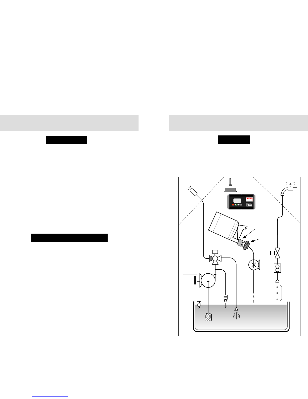
The operations of the Gen III are managed by a digital controller
and a number of electro-mechanical components. The controller
gets information about dosing and agitating the insecticide from
an electronic tag that is embedded in the Smart Cap on the
insecticide cartridge.
Batch Control
Pump Intake
& Filter
Water
source
Nozzle
Circuit
Motor
Pump
Agitate Line
Discharge
Auto
Drain
Valve
Float
Switch
Supply
Valve
Flow
Meter
Flow
Regulator
2" Air
Gap
Insecticide
Cartridge
Smart
Cap
Smart
Coupler
Agitation
Valve
Dosing
Pump
Batch Tank
Digital Controller
Remote Receiver
Antenna

Section 2
Functionality and Components
Section 2
Functionality and Components
• Digital Controller – accepts user input, displays unit operating
mode and status, controls electromechanical components.
• Remote Receiver & Antenna – receives signal from handheld
remote transmitter. Receiver located on underside of enclosure
lid.
• LED warning light – annunciates unit status – warning, misting,
suspended due to error or empty cartridge. Located on top of
enclosure lid.
Components – Interface and Controls
• Supply Valve – opens to allow water to flow from faucet into
batch tank.
• Flow Meter – on inlet water line, measures flow into the batch
tank. Used to control insecticide dosing and error condition
calculations.
• Float Switch – closes supply valve when batch tank is full.
• Flow Regulator – ensures smooth flow of water into batch tank.
Positioned to ensure 2” air gap between water supply and batch
tank contents.
Components – Fresh Water Flow Control
• Remote Transmitter – 3-button remote enables the user to start
a mist, stop a mist and skip the next scheduled mist.
• Key – for lock that is located on top front wall of enclosure.
Other Components
• Insecticide Cartridge –vented two-chamber bottle containing
one of a number of botanical insecticides.
• Smart Cap – embedded RFID (radio frequency identification)
tag programmed with information to control dosing, agitation,
cartridge volume display and misting limits.
• Smart Coupler – accepts snap-in Smart Cap, reads the
information stored on it and passes it to the controller.
• Dosing Pump – precisely meters insecticide concentrate from
the cartridge into the batch tank.
Components – Insecticide Flow Control
Components – Agitation and Atomization
• Batch Tank – 2 gallon plastic tank with enough capacity to
enable a 60 nozzle circuit to mist for 120 seconds.
• Pump & Motor – atomizes batch tank contents through nozzle
circuit. Pump pressure typically set to 240 psi.
• Agitation Valve – One path through the valve routes fluid to the
nozzle circuit. The other path recirculates fluid in the batch tank
through the agitation line. Each mist (including REMOTE
MISTs) will be preceded by an agitation cycle that will ensure
thorough mixing of the batch tank contents prior to misting. In
addition, there is a once daily agitation that is independent of any
AUTO or REMOTE MIST. The agitating valve also eliminates
the possibility of a siphon emptying the batch tank contents.
• Pump Intake Line and Filter – Pump intake positioned near
bottom of batch tank. Filter ensures debris is not drawn into
pump and nozzle circuit.
• Agitation Line – during agitation, batch tank contents are
recirculated to ensure thorough mixing prior to misting.
• Auto-Drain Valve – ensures rapid increase in nozzle circuit
pressure on pump startup and rapid decrease on shutdown.
• Enclosure and Lid – sturdy powder-coated galvanealed metal
walls, locking lid, and aluminum chassis and feet.
• Shroud – black plastic inner shelf with well for snap-in
insecticide cartridge. Supports recessed controller and pressure
gauge.
Components - Structural
Section 3
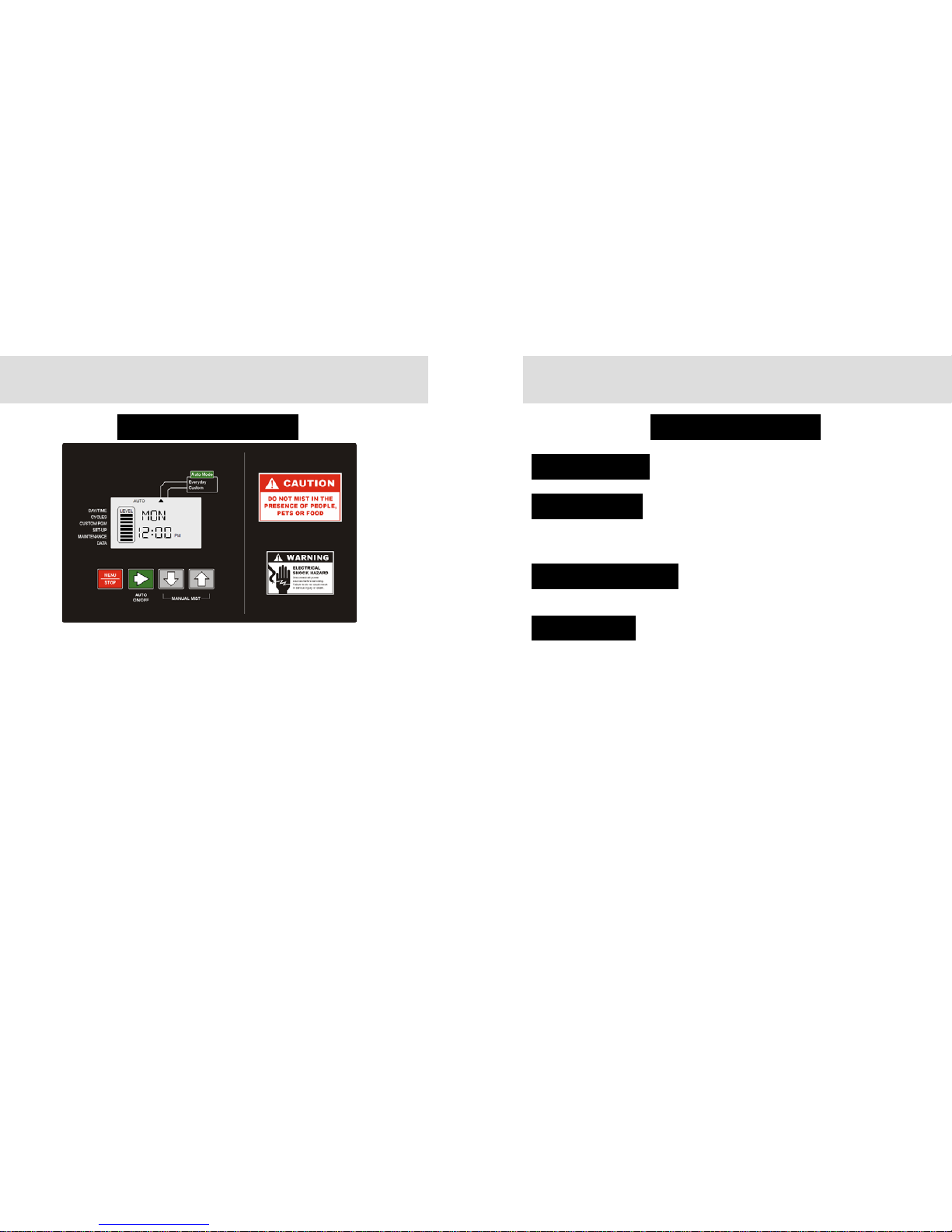
Operating Instructions
• When the unit is powered up and idle, the controller display
indicates four pieces of information:
1.Day of the week
2.Time of day
3.System mode (Off, On, Auto-Everyday, Auto-Custom)
4.Cartridge Level (each bar indicating cartridge 1/8
th
full)
• Pressing Green ► button will cycle through each of four System
Modes. Active mode indicated at top of display.
1.OFF – Unit will perform a daily agitation cycle and otherwise
sit idle.
2.ON – Unit will allow Remote and MANUAL MISTs, but no
AUTO MISTs.
3.AUTO-EVERYDAY – Misting program runs daily.
4.AUTO-CUSTOM – Misting program runs on days set in
CUSTOM PGM menu.
• Pressing Red MENU/STOP button displays triangular cursor by
DAY/TIME position on left side of display. Use ▲ or ▼ buttons to
cycle through menu structure. Use Green ►button to select menu
item and view or change data element within that item.
• Within a menu item, the convention is that the flashing data
element can be changed with the ▲ or ▼ buttons. Move to the
next data element with the Green ► button.
• Exit the menu item by pressing the MENU button. The unit will
revert to previous System Mode in 3 minutes if the MENU button is
not pressed.
Programming the Controller
Section 3
Operating Instructions
Set the Day of the Week and the Time of Day.
DAY/TIME Menu
Configure the mist time and duration of each of
the twelve possible AUTO MIST Cycles (Each
with unique duration and time of day.)
CYCLES Menu
Configures the days of the week for AUTO
MISTing in the AUTO-CUSTOM PGM
mode. (Turn each day OFF or ON.)
CUSTOM PGM Menu
DST Turn daylight savings time switch ON or OFF.
REM Set the duration for mists triggered by the remote
transmitter. (Values from OFF to 120 seconds)
LRN Program unit to recognize a specific remote transmitter.
Hold down Green ► button for 5 seconds and wait for
countdown to begin. Press and hold any button on the
remote transmitter. When DONE flashes in the display,
the transmitter is programmed.
MAN Set the duration for mists triggered by a MANUAL MIST
(pressing ▲ and ▼ buttons simultaneously for 2 seconds.)
NOZ Set the Number of nozzles in the circuit attached to the
unit. If Zone Kit installed, there are separate displays for
NZ1 and NZ2.
SEN Turn (optional) wind sensor ON or OFF
WND Set max wind speed (above which wind sensor reading
inhibits mist.)
AGT Set time of once daily off-cycle agitation. (Note: Agitation
duration preceding AUTO MIST is read from cap.)
ZN1/ZN2 Enable or disable misting in Zone 1 and (optional) Zone 2.
SET-UP Menu
Controller Menu Structure
 Loading...