

MistAway Gen II Operating Manual
Gen II Tankless
Misting System
Operating Manual
MistAway Systems • 1-866-485-7255 • www.mistaway.com

THIS PAGE INTENTIONALLY LEFT BLANK
The MistAwayTM Gen II Tankless Misting System
1
Position the Gen II Unit
2
Install the Water Supply Line
3
Connect to the Nozzle Circuit
4
Connect the Electrical Power
5
Set DST & the Date/Time
6
Set the Number of Nozzles
7
Program Remote Transmitter
8
Run the Initial Inspection Cycle
INSTALLATION GUIDE
9
Drain the Internal Mixing Vessel
10
Insert the Insecticide Cartridge
11
Set the Remote Mist Duration
12
Set the Manual Mist Duration
13
Program the Auto Mist Cycles
14
Program the Auto Mist Days
15
Set the System Mode
16
Run Initial Mist Cycle
A
Operating the Remote
B
The Controller Menus
C
Frequently Asked Questions
APPENDICES
D
Troubleshooting
E
Interpreting “ERR” Error Conditions
F
Product Warranty

THIS PAGE INTENTIONALLY LEFT BLANK
The MistAwayTM Gen II Tankless Misting System
This Installation Guide details the 16 steps needed to successfully install the MistAwayTM
Gen II Tankless Misting System.
During the installation process you will need to frequently navigate the Gen II’s digital controller.
To access the controller menu, simply press the gray “MENU” button on the controller. The
cursor, a small triangle, will start flashing on the left side of the controller window. Turn the
SELECT knob to align the cursor with the appropriate menu path and then push the SELECT
knob to enter that menu path.
Pressing “MENU” or the red “STOP” button will exit the menu path and return to the main screen.
1
A. Select a suitable flat area for the MistAwayTM Misting System. The location should be:
In an area free from any localized flooding, and out of the spray arc of any sprinkler heads.
Within 12 feet of an electrical outlet with GFI protection
Within 25 feet of a hose bib or other water source.
B. Remove the Gen II from the box, open the enclosure lid, and verify all components present.
C. The MistAway
o Gen II Tankless Misting Unit
o Remote Transmitter
o Screw-on Remote Antenna
o Hose Bib Adapter
o 25’ of Black 3/8” Nylon Tubing
o Two keys to the enclosure lid lock
Position the Gen II Unit
o The unit may be located greater than 25 feet from a water source; however,
additional tubing must be purchased.
o Care should be taken to avoid excessive water pressure drop over an extended
length of the tubing.
TM
Gen II Tankless Misting System Kit includes the following components:
D. Mount the unit on cement pavers or other solid, flat surfaces that provide a firm, level surface
to support the unit.
The MistAwayTM Gen II Tankless Misting System
2
• Securely attach the supplied hose bib adapter to the nearest hose bib.
Ensure that the rubber washer inside the hose bib adapter did not separate from the
adapter during shipping.
• Connect the supplied 25 ft of 3/8" black nylon tubing to the push-to-connect fitting on the hose
bib.
• Run the 3/8" nylon tubing to the Gen II unit. It is recommended to bury the line inside of a PVC
pipe in order to prevent the line from being accidentally cut during yard maintenance.
Verify that the water flow rate at the Gen II unit is such that a 1 gallon jug can be filled in
45 seconds or less. A water flow less than 1 gallon per 45 seconds may cause
inaccuracies in the internal flow meter.
• Attach the 3/8" black nylon tubing line to the 3/8" push-to-connect fitting on the bulkhead
connections panel of the Gen II unit.
• Turn the water on at the hose bib and inspect the fittings and nylon tubing for leaks.
Install the Water Supply Line
3
Connect to the Nozzle Circuit
• Connect the Gen II unit to nozzle circuit by attaching the ¼” nozzle circuit line to the ¼” push-to-
connect fitting on the Gen II connections panel.
• If the Gen II is equipped with a Zone Kit, connect the Zone 1 nozzle circuit to the upper ¼” push-
to-connect fitting, and connect the Zone 2 nozzle circuit to the lower ¼” bulkhead fitting
• Check valves and anti-siphon valves are not required when using the Gen II unit. The internal
solenoid valve prevents both siphoning and excessive nozzle circuit drain back
NOTE: If the first nozzle is located more than 30 ft from the Gen II unit, it is highly
recommended to run 3/8" tubing from the Gen II to the first nozzle in order to avoid
significant pressure loss in the line, and corresponding degradation in the quality of the
mist at distant nozzles.
PM
LEVEL
PM
OFF
LEVEL
The MistAwayTM Gen II Tankless Misting System
4
• Connect the Gen II power cord to the nearest electrical outlet.
• NOTE: You must plug the Gen II power cord into a
GFI/GFCI protected outlet. The use of extension cords is
not approved by MistAway Systems, Inc.
Connect the Electrical Power
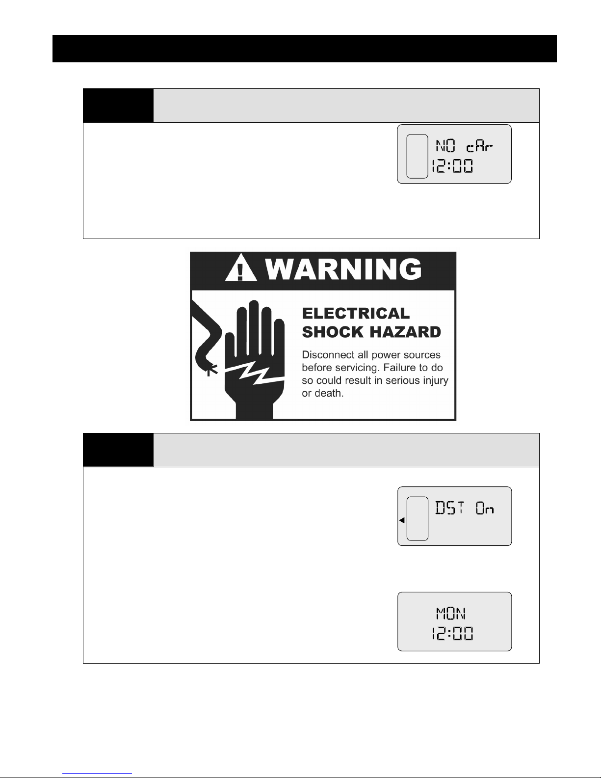
• Open the Gen II lid and observe the LCD display. It should be
flashing "NO cAr" (i.e., No Cartridge) and display a time.
5
• Prior to setting the Date/Time you need to first set the Daylight
Savings Time indicator ON or OFF.
• Navigate to SET-UP DST.
• Push SELECT to set DST as ON or OFF.
• Press the MENU button when finished.
o "DST ON" would be the setting used in summer months.
• Next navigate to the DAY/TIME menu.
• Turn the SELECT knob to set the day of the week.
• Press SELECT again to set the hour, followed by the minutes.
• Press the MENU button when finished.
Set DST and the Date/Time
LEVEL
LEVEL
LEVEL
LEVEL
The MistAwayTM Gen II Tankless Misting System
6
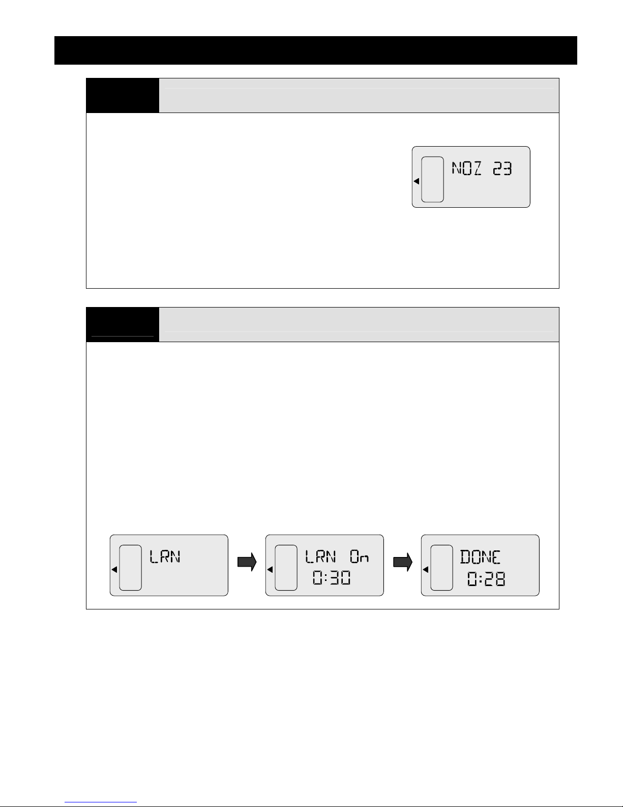
• Navigate to SET-UP NOZ.
• Press SELECT while NOZ is flashing, and the number of
nozzles will start to flash.
• Turn the SELECT knob to set the number of nozzles in the
installation.
• Press the MENU button to exit.
• If the Gen II unit is equipped with a Zone Kit, you will instead need to navigate to NZ1, set the
number of nozzles in Zone 1, and then navigate to NZ2, and set the Number of nozzles in Zone
2
Set the Number of Nozzles
• The ZN1 and ZN2 functions may be used to turn Zone 1 and Zone 2 on/off.
7
• Attach the provided antenna to the Gen II unit by screwing it to the connector on the top of the
Gen II enclosure lid.
Program Remote Transmitter
• Remove the small, raised plastic cover on the back of the remote and randomly set the DIP
switches. A small nail, toothpick or safety pin works well.
• Changing the DIP switches from the standard position will minimize the possibility of interference
from other mosquito systems or garage door and gate transmitters.
• Navigate to SET-UP LRN and hold the SELECT button for 5 seconds.
• The system will begin a 30 second countdown. Hit any button on the remote until the display
changes to "DONE".
• The remote transmitter is now programmed to work with the Gen II.
LEVEL
LEVEL
LEVEL
The MistAwayTM Gen II Tankless Misting System
8
• Use a flathead screwdriver to remove the small circular black plastic cover on the bulkhead
fittings panel. Insert the flathead screwdriver through this hole and locate the pump pressure
adjustment screw
• Navigate to the INS function on the MAINTENANCE
menu. INS will be flashing.
• Hold down the SELECT button to activate the Inspection
cycle
• The system will begin filling the internal reservoir with
fresh water. Use this opportunity to check for leaks in the
water line connection.
• Once the internal reservoir is filled with fresh water, the system will mist for 5 continuous
minutes, automatically refilling the mixing vessel as needed.
o NOTE: For very large installations, the system may stop before 5 minutes if the water
• Use the flathead screwdriver to turn the pump pressure adjustment screw until the pressure
gauge reads 240 psi. Do NOT allow the system pressure to exceed 240 psi.
• Inspect the nozzle circuit for any leaks or clogged nozzles and correct as necessary.
• If a Zone Kit is installed in the Gen II, you will need to inspect
both zones.
• To inspect Zone 1, navigate to INS 1 on the
MAINTENANCE menu and hold SELECT for 5 seconds.
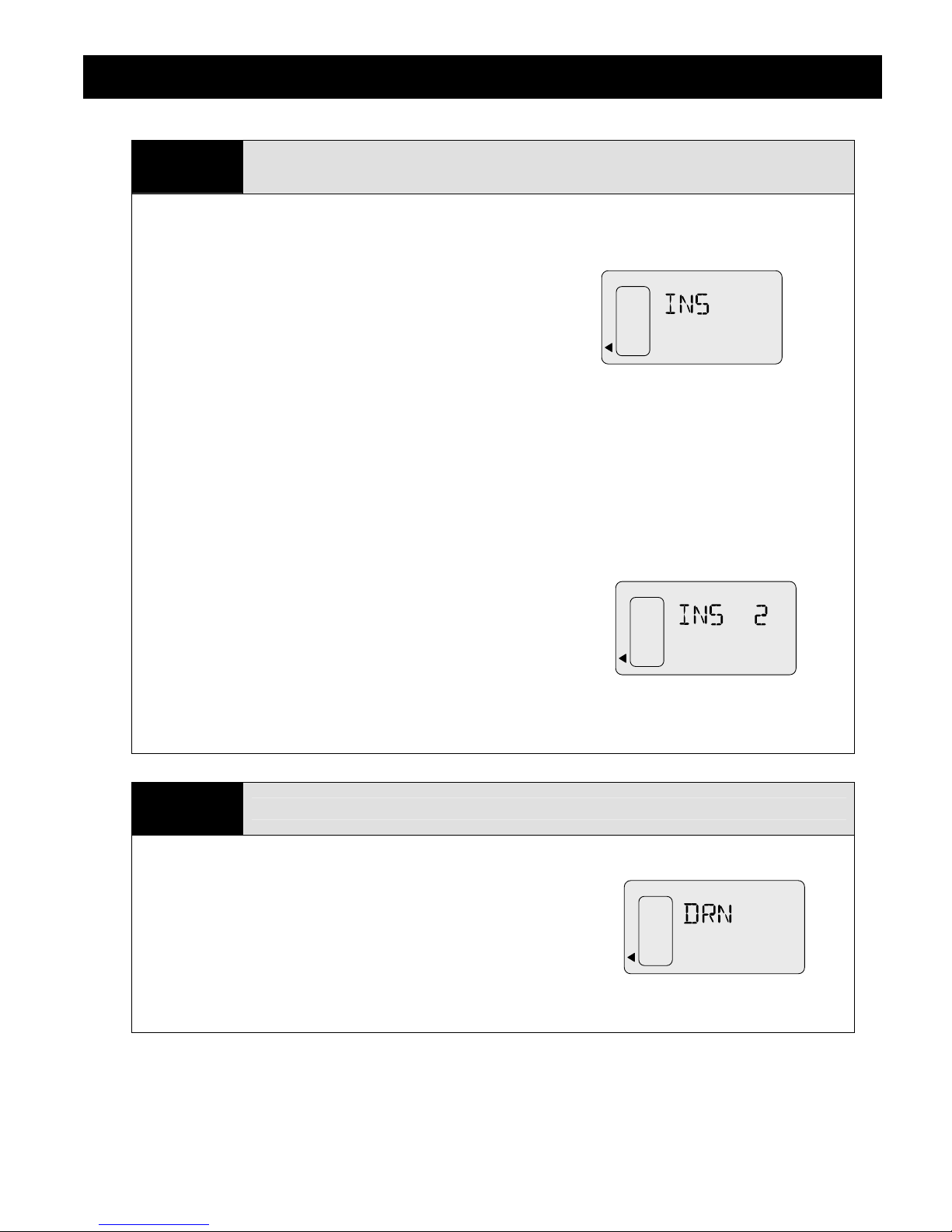
• To inspect Zone 2, navigate to INS 2 on the
MAINTENANCE menu and hold SELECT for 5 seconds.
Run the Initial Inspection Cycle
flow rate into the machine is less than the amount misting out. In general, however, if
the system stops prior to 5 minutes, there is likely a leak in the nozzle circuit.
• Ensure the pump pressure is set such that neither Zone 1 nor Zone 2 exceeds 240 psi
when misting.
9
• Once the inspection cycle is complete, the internal mixing vessel should be drained in order to
allow a full batch of insecticide mixture to be rebuilt.
• To Drain, navigate to MAINTENANCE DRN and hold the
SELECT button for 5 seconds.
• After a Warning duration of 30 seconds, the system will Drain
the contents of the mixing vessel through the nozzle circuit.
Drain the Internal Mixing Vessel
• If a Zone Kit is installed, the system will only drain the internal
reservoir through the Zone 1 nozzle circuit.
 Loading...