

MistAway Gen 1.2 Operating Manual
Drum-based
Misting System
Operating Manual
MistAway Systems, Inc. • 1-866-485-7255 • www.mistaway.com
The MistAwayTM Drum-based Misting System
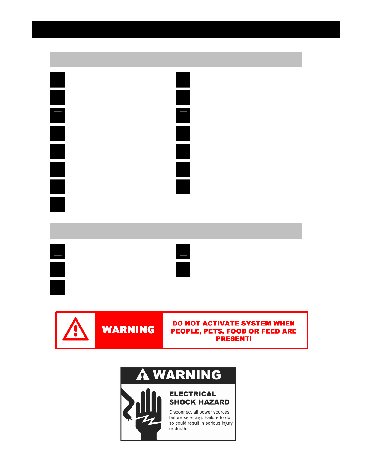
INSTALLATION & SET-UP GUIDE
1
Assemble the System
2
Connect to the Nozzle Circuit
3
Connect the Electrical Power
4
Set the Date & Time
5
Set the Number of Nozzles
6
Program Remote Transmitter
7
Run the Initial Inspection Cycle
8
Fill Drum/Set LEVEL Indicator
9
Set the Remote Mist Duration
10
Set the Manual Mist Duration
11
Program the Auto Mist Cycles
12
Program the Auto Mist Days
13
Set the System Mode
14
Run Initial Mist Cycle
15
Cover Misting System Chassis
A
Operating the Remote
B
The Controller Menus
C
Frequently Asked Questions
APPENDICES
D
Troubleshooting
E
Product Warranty
This Installation Guide details the 15 steps needed to successfully install the MistAwayTM
Drum-based Misting System.
During the installation process you will need to frequently navigate the Misting System’s digital
controller.
To access the controller menu, simply press the gray “MENU” button on the controller. The
cursor, a small triangle, will start flashing on the left side of the controller window. Turn the
SELECT knob to align the cursor with the appropriate menu path and then push the SELECT
knob to enter that menu path.
Pressing “MENU” or the red “STOP” button will exit the menu path and return to the main screen.
The MistAwayTM Drum-based Misting System
1
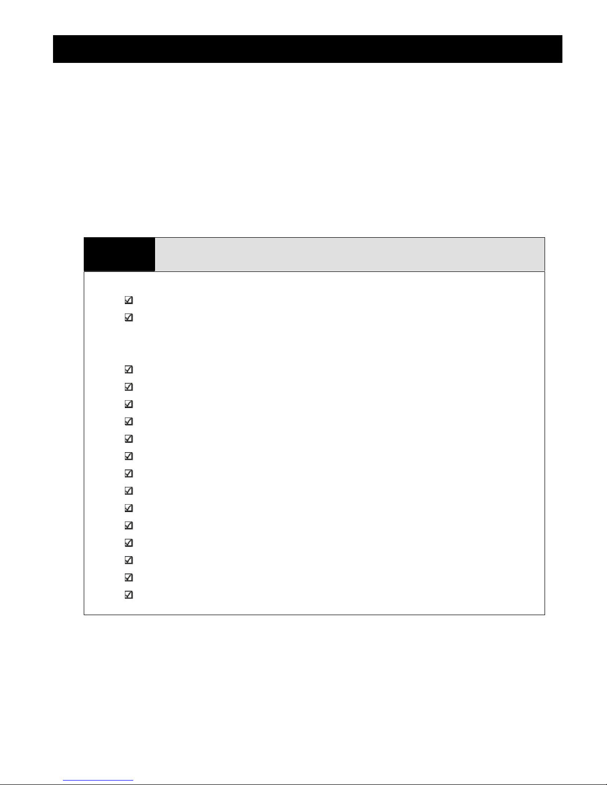
A. Select a suitable flat area for the MistAwayTM Misting System. The location should be:
In an area free from any localized flooding, and out of the spray arc of any sprinkler heads.
Within 12 feet of an electrical outlet with GFI protection
B. Remove chassis assembly from the box and verify all components present.
C. The MistAwayTM Drum-based Misting System kit includes the following components
Chassis assembly with controller, pump, motor, and agitator (if so optioned)
Drum and pre-drilled drum lid
Screw-on Remote antenna
Remote Transmitter
Drum Lid Cover
Pump suction pipe, with pre-attached suction strainer
Float Switch Assembly (pre-attached to pump suction pipe)
Auto-Drain Valve Assembly (valve attached to 8” of black ¼” nylon tubing)
Agitator pipe (if so optioned)
4 each of ¼” stainless hex-head bolts, flat washers, lock washers, and nuts
Assemble the Drum-based Misting System
¾” rubber grommet (for pump suction – 55 gallon systems only)
½” rubber grommet (for agitator; included with all kits – 55 gallon systems only)
¼” rubber grommet (for auto-drain valve – 55 gallon systems only)
2 spare black nylon anti-vibration washers
The MistAwayTM Drum-based Misting System
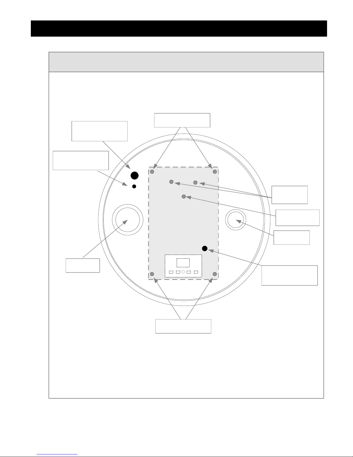
Assemble the Drum-based Misting System (continued)
D. Install the provided rubber grommets as per the below drawing of the drum lid (55 gallon systems
only).
Chassis Bolts
Pump Suction
Use ¾” GROMMET
Auto-Drain Valve
Use ¼” GROMMET
Tank Vent
Ports
Float Switch
Cable Port
Small Bung
Large Bung
Agitator Tube Port
Use ½” GROMMET
Chassis Bolts
E. Thread the float switch cable/connector (attached to the pump suction strainer pipe) up through
the ½” hole nearest the center of the drum.
F. Lay the Misting System chassis on its side on the drum lid
G. Attach the float switch connector to the connector with the BLUE wires, located near the front of
the underside of the chassis.

The MistAwayTM Drum-based Misting System
Assemble the Drum-based Misting System (continued)
H. Verify other connectors are tight:
o The YELLOW wires should be connected to the BLACK & WHITE wires for the
agitator (if equipped)
o The ORANGE wires should be connected to the Zone Solenoid Valve (if equipped)
o The RED wires are not used at this time.
I. Align the chassis with the four holes on the drum lid. The chassis should be oriented such that
the pump is on the same side as the large bung in the drum lid.
J. Insert the ½” pump suction line (with float switch attached) up through the ¾” grommet on the
drum lid and into the ½” fitting on the pump.
o Push the pipe in firmly and then pull it back to ensure it is locked into the fitting.
o The float switch float must be oriented towards the center of the drum.
K. Insert the ¼” black tubing of the auto drain valve assembly up through the ¼” grommet in the
drum lid and into the ¼” fitting on the pump discharge.
o Push the tubing in firmly and then pull back to ensure it is locked into the fitting.
L. If the system is equipped with an agitator, insert the agitator line up through the ½” grommet in
the drum lid, through the hole in the chassis, and into the ½” fitting on the agitator.
o Push the tubing in firmly and then pull back to ensure it is locked into the fitting.
M. Secure the chassis to the drum lid with the provided bolts, flat washers, lock washers and
nuts.
o Use two 7/16” wrenches to secure the bolts.
o Installation sequence is bolt, chassis, drum lid, flat washer, lock washer, nut.
o The flat washer, lock washer, and nut should be on the underside of the drum lid.
o Note that the four chassis mounting holes in the drum lid have been oversized to ease
assembly. Ensure that the chassis mounting bolts are tightened so that the chassis
does not slide around in the mounting holes
N. VERIFY THAT THE FLOAT SWITCH FLOAT IS ORIENTED TOWARDS THE CENTER OF
THE DRUM and then secure the drum lid to the drum, ensuring that lip is tightly pressed down
to the drum around the entire circumference of the drum.
O. Screw the Remote Antenna to the threaded connector on the chassis (located just behind the
controller).
P. Verify that the anti-vibration spacers are installed on the hinge pins between the enclosure lid
and the enclosure
o If the anti-vibration spacers have become dislodged during shipment, two spares
spacers have been provided with the Misting System.
o Use a small flat-tipped screwdriver to replace the spacers on the hinge pins, if
necessary.
PM
LEVEL
LEVEL
PM
OFF
The MistAwayTM Drum-based Misting System
2
• Connect the Misting System to the nozzle circuit by attaching the ¼” nozzle circuit line to the
open ¼” push-to-connect fitting on the “T” fitting on the pump discharge.
• If the Misting System is equipped with a Zone Kit, connect the Zone 1 nozzle circuit to the ¼”
push-to-connect fitting on the TOP of the zone solenoid, and connect the Zone 2 nozzle circuit
to the ¼” push-to-connect fitting on the BOTTOM of the zone solenoid.
• If the nozzle circuit features risers, it’s recommended to install an anti-siphon valve
• NOTE: If the first nozzle is located more than 30 ft from the drum, it is highly recommended to
run 3/8" tubing from the drum to the first nozzle in order to avoid significant pressure loss in the
line, and corresponding degradation in mist quality at distant nozzles.
Connect to the Nozzle Circuit
3
• Connect the Misting System power cord to the nearest
electrical outlet.
• NOTE: You must plug the Misting System power cord
into a GFI/GFCI protected outlet.
• The use of extension cords is not approved by MistAway
Systems, Inc.
Connect the Electrical Power
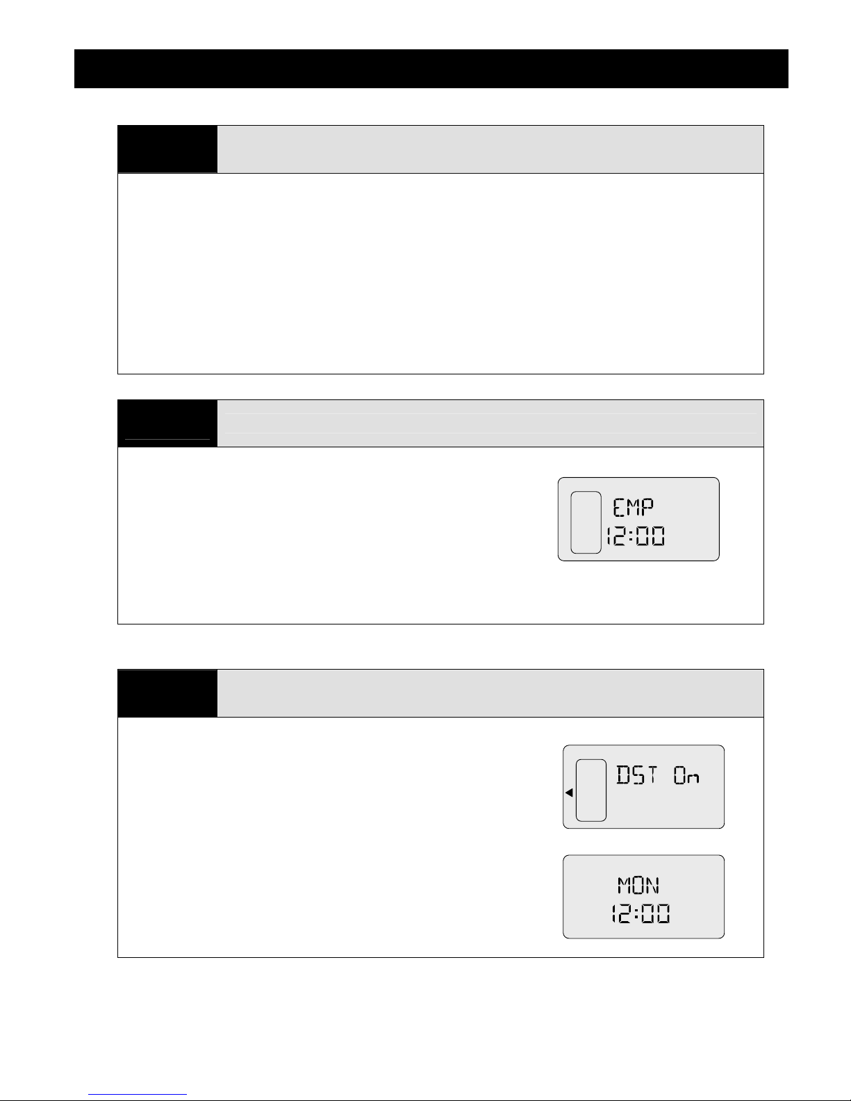
• Open the digital controller lid and observe the LCD display. It should be flashing "EMP" (i.e.,
“Empty”) and display a time.
4
• Prior to setting the Date/Time you need to first set the Daylight
Savings Time indicator ON or OFF.
• Navigate to SET-UP DST.
• Push SELECT to set DST as ON or OFF.
• Press the MENU button when finished.
o "DST ON" would be the setting used in summer months.
• Next navigate to the DAY/TIME menu.
• Turn the SELECT knob to set the day of the week.
• Press SELECT again to set the hour, followed by the minutes.
• Press the MENU button when finished.
Set the Date & Time
LEVEL
LEVEL
LEVEL
LEVEL
The MistAwayTM Drum-based Misting System
5
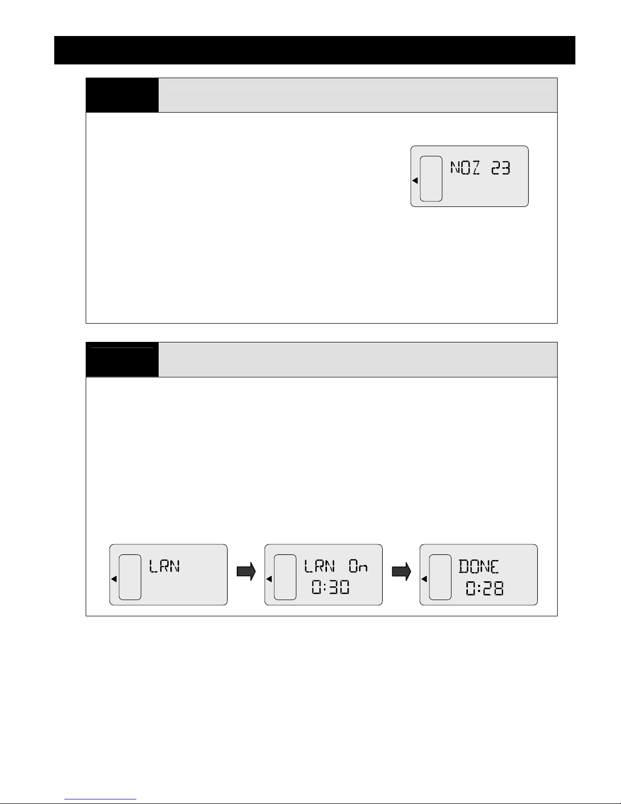
• Navigate to SET-UP NOZ.
• Press SELECT while NOZ is flashing, and the number will
start to flash.
• Turn the SELECT knob to set the number of nozzles in the
installation.
• Press the MENU button to exit.
• If the Misting System is equipped with a Zone Kit, you will instead need to navigate to NZ1, set
the number of nozzles in Zone 1, and then navigate to NZ2, and set the Number of nozzles in
Zone 2
Set the Number of Nozzles
• The ZN1 and ZN2 functions may be used to turn Zone 1 and Zone 2 on/off.
• NOTE: For 125 gallon systems, you must set the number of nozzles to HALF the actual
number in order for the level indicator to read correctly.
6
• Verify that the provided antenna is securely attached to the connector on the chassis, located
just behind the controller enclosure.
Program Remote Transmitter
• Remove the small, raised plastic cover on the back of the remote and randomly set the DIP
switches. A small nail, toothpick or safety pin works well. Changing the DIP switches from the
standard position will minimize the possibility of interference from other mosquito systems or
garage door and gate transmitters.
• Navigate to SET-UP LRN and hold the SELECT button for 5 seconds.
• The system will begin a 30 second countdown. Hit any button on the remote until the display
changes to "DONE".
• The remote transmitter is now programmed to work with the MistAway
TM
Misting System.
 Loading...