

Page 1

B IU RO @M IS SI ON AI R. PL S ER WI S@ MI SS IO NA IR .P L W WW .M IS SI ON AI R. PLT EL . (+ 48 ) 79 7 45 1 11 1
E L E K T R Y C Z N Y P R Z E W Ó D G R Z E W C Z Y D O Z E W N Ę T R Z Y C H
S Y S T E M Ó W P R Z E C I W O B L O D Z E N I O W Y C H
M A I C E - 2 0
I N S T R U K C J A O B S Ł U G I
Instructions in English: page 28
Page 2

Misja marki Mission Air® jest jasna - tworzyć nowoczesne i ekologiczne
rozwiązania, które zapewnią Państwu wygodę i komfort poprzez
dostarczanie zeroemisyjnych produktów w zakresie elektrycznego
ogrzewania i klimatyzacji.
Jako odpowiedzialna firma dążymy do minimalizowania negatywnego wpływu na
środowisko naturalne, poprzez projektowanie i produkcję wydajnych systemów, które
świetnie współpracują z odnawialnymi źródłami energii i zmniejszają tym samym emisję
szkodliwych dla naszej planety gazów.
Troska o środowisko naturalne to jeden z naszych priorytetów!
www.missionair.pl
O NAS
B IU RO @M IS SI ON AI R. PL S ER WI S@ MI SS IO NA IR .P L W WW .M IS SI ON AI R. PLT EL . (+ 48 ) 79 7 45 1 11 1
INSTRUKCJA OBSŁUGI PRZEWODU MA ICE-20
P L
Page 3
B IU RO @M IS SI ON AI R. PL S ER WI S@ MI SS IO NA IR .P L W WW .M IS SI ON AI R. PLT EL . (+ 48 ) 79 7 45 1 11 1
The English manual is is available on our website.
Das Handbuch in deutscher Sprache ist auf unserer Website verfügbar.
Niniejsza instrukcja została opracowana specjalnie dla Ciebie, aby między
innymi pomóc zrozumieć, jak działa Twój system przewodów grzewczych
MA ICE-20 od Mission Air®, a co za tym idzie, jak obsługiwać go z
maksymalną wydajnością.
Instrukcja pomoże Ci w bezpiecznej instalacji i odpowie na pytania, które
mogą pojawić się podczas montażu.
Instrukcja powinna być przeczytana i w pełni zrozumiana przed instalacją systemu.
Błędna instalacja lub brak wypełnienia karty gwarancyjnej oraz planu instalacji jest
jednoznaczny z utratą ochrony gwarancyjnej.
Dziękujemy za zaufanie oraz zakup naszych produktów. Jesteśmy pewni,
że przewody grzewcze MA ICE-20 od Mission Air® zagwarantują ciepło w
każdej sytuacji.
www.missionair.pl
Посбник українською мовою є на нашому сайт.
INSTRUKCJA OBSŁUGI PRZEWODU MA ICE-20
3
P L
Page 4

OPIS PRODUKTU..........................................................................................................................6
SPECYFIKACJA.............................................................................................................................7
OSTRZEŻENIA..............................................................................................................................9
WYBRANE SPOSOBY MONTAŻU................................................................................................10
INSTALACJA PRZEWODU GRZEJNEGO........................................................................................13
INSTALACJA STEROWANIKÓW I CZUJNIKÓW............................................................................21
TEST REZYSTANCJI IZOLACJI ZA POMOCĄ MULTIMETRU CYFROWEGO........................................22
TEST REZYSTANCJI KABLA GRZEJNEGO.......................................................................................22
ROZWIĄZYWANIE PROBLEMÓW...............................................................................................23
PLAN ROZMIESZCZENIA SYSTEMU..............................................................................................25
WARUNKI GWARANCJI.............................................................................................................26
SPIS TREŚCI
1.
2.
3.
4.
5.
6.
7.
8.
9.
10.
11.
B IU RO @M IS SI ON AI R. PL S ER WI S@ MI SS IO NA IR .P L W WW .M IS SI ON AI R. PLT EL . (+ 48 ) 79 7 45 1 11 1
INSTRUKCJA OBSŁUGI PRZEWODU MA ICE-20
4
P L
Page 5

OSTRZEŻENIE
Ryzyko porażenia prądem i pożaru!
Jeśli system ulegnie uszkodzeniu lub nie zostanie prawidłowo zainstalowany, może dojść do pożaru lub
porażenia prądem, co może w efekcie skutkować poważnymi obrażeniami ciała lub uszkodzeniem mienia.
Należy uważnie przestrzegać ostrzeżeń i wskazówek zawartych w niniejszej instrukcji.
Ważne jest, aby system był instalowany wyłącznie przez wykwalifikowanych elektryków, którzy są
zaznajomieni z prawidłowym wymiarowaniem, instalacją, budową i działaniem systemu ogrzewania oraz
związanymi z nim zagrożeniami. Instalacja musi być zgodna ze wszystkimi krajowymi i lokalnymi
przepisami elektrycznymi. Jeśli nie znasz tych wymagań, skontaktuj się z certyfikowanym elektrykiem.
Jeśli system jest uszkodzony, należy go wymienić. Nie próbuj samodzielnie łączyć ani naprawiać żadnej
części systemu. Przewodów grzewczych nie należy skracać. Długość przewodu należy dobrać do
konkretnego planu instalacji.
Bezpieczeństwo i niezawodność każdego systemu ogrzewania zależy od jego właściwego projektu,
instalacji i testowania. Nieprawidłowa instalacja lub niewłaściwa obsługa produktu może spowodować
uszkodzenie przewodu grzejnego, elementów systemu i mienia, a także może stworzyć ryzyko pożaru lub
porażenia prądem. Wskazówki zawarte w niniejszej instrukcji są bardzo istotne. Należy przestrzegać ich
uważnie, aby zminimalizować zagrożenia i zapewnić niezawodne i bezpieczne działanie systemu.
B IU RO @M IS SI ON AI R. PL S ER WI S@ MI SS IO NA IR .P L W WW .M IS SI ON AI R. PLT EL . (+ 48 ) 79 7 45 1 11 1
INSTRUKCJA OBSŁUGI PRZEWODU MA ICE-20
5
P L
Page 6

trwałe rozwiązanie problemów spowodowanych niskimi temperaturami,
poprawę bezpieczeństwa, zapewniając natychmiastową ulgę od śniegu i lodu,
oszczędności czasu, poprzez brak konieczności odśnieżania chodników, podjazdów czy schodów,
oszczędności finansowe, związane z brakiem konieczności wynajmowania firm lub maszyn do
odśnieżania,
niskie koszty eksploatacji,
efektywne wykorzystanie mocy przy zastosowaniu właściwych systemów sterowania.
idealny do podjazdów, parkingów, chodników, schodów, ramp, mostów i wielu innych zastosowań,
do stosowania w betonie, asfalcie, kostce brukowej lub kamiennej oraz płytkach ceramicznych lub
kamiennych,
połączenie jednopunktowe,
kabel dwużyłowy,
cichy, wydajny i bezpieczny,
nie emituje pola elektromagnetycznego (EMF),
łatwa i elastyczna instalacja,
trwała konstrukcja,
25-letnia gwarancja na wady produkcyjne.
OPIS PRODUKTU
System MA ICE-20 został zaprojektowany w celu zapewnienia ochrony przeciwzamarzaniowej oraz
ochrony przeciwśniegowej zewnętrznych części budynku, takich jak wejścia, schody, chodniki, podjazdy,
rampy itp.
Instalacja systemu zapewnia wiele korzyści. Wśród nich możemy wymienić między innymi:
Cechy systemu MA ICE-20:
B I U R O @ M I S S I O N A I R . P L S E R W I S @ M I S S I O N A I R . P L W W W . M I S S I O N A I R . P LT E L . ( + 4 8 ) 7 9 7 4 5 1 1 1 1
INSTRUKCJA OBSŁUGI PRZEWODU MA ICE-20
6
P L
Page 7

przycinać lub skracać,
krzyżować ze sobą i innymi przewodami np. zasilającymi,
układać w taki sposób, że będą się ze sobą stykać.
SPECYFIKACJA
UWAGA!
Kabli grzewczych w żadnym przypadku nie wolno:
W ŻADNYM PRZYPADKU NIE WOLNO INSTALOWAĆ KABLI BEZ
NADZORU URZĄDZEŃ STERUJĄCYCH!
KONSTRUKCJA KABLA
NAPIĘCIE ZNAMIONOWE
MOC LINIOWA
DOSTĘPNE DŁUGOŚCI
MAX. TEMPERATURA ZNAMIONOWA
PRZEKRÓJ KABLA
PROMIEŃ GIĘCIA
IZOLACJA ZEWNĘTRZNA
IZOLACJA PRZEWODU
EKRANOWANIE
KABEL ZASILAJĄCY
MIN. TEMPERATURA INSTALACJI
okrągły, podwójny przewód ze 100% ekranem
230 V
20 W/m
od 4 m do 195 m
105℃
6 - 6,5 mm
38 mm
XLPE
PVC
PVC
5℃
3 m długości
B I U R O @ M I S S I O N A I R . P L S E R W I S @ M I S S I O N A I R . P L W W W . M I S S I O N A I R . P LT E L . ( + 4 8 ) 7 9 7 4 5 1 1 1 1
INSTRUKCJA OBSŁUGI PRZEWODU MA ICE-20
7
P L
Page 8

TYP
MA ICE-20 4M
MA ICE-20 7,5M
MOC LINIOWA
W/M
DŁUGOŚĆ
(M)
A
MA ICE-20 12,5M
20
4
0,4
20
7,5 0,7
20 12,5 1,1
MOC
CAŁKOWITA (W)
80
150
250
MA ICE-20 19M
20 19 1,7 380
OPORNOŚĆ (Ω)
661,3
352,7
211,6
139,2
MA ICE-20 25M
MA ICE-20 31M
MA ICE-20 40M
20
25
2,3
20
31 2,8
20 40 3,6
500
620
800
MA ICE-20 50M
20 50 4,5 1000
105,8
85,3
66,1
52,9
MA ICE-20 60M
MA ICE-20 70M
MA ICE-20 85M
20
60
5,5
20
70 6,4
20 85 7,7
1200
1400
1700
MA ICE-20 100M
20 100 9,1 2000
44,1
37,8
31,1
26,5
MA ICE-20 120M
MA ICE-20 135M
MA ICE-20 150M
20
120
10,9
20
135 12,3
20 150 13,6
2400
2700
3000
MA ICE-20 170M
20 170 15,5 3400
22,0
19,6
17,6
15,6
MA ICE-20 195M
20 195 17,7 3900 13,6
B I U R O @ M I S S I O N A I R . P L S E R W I S @ M I S S I O N A I R . P L W W W . M I S S I O N A I R . P LT E L . ( + 4 8 ) 7 9 7 4 5 1 1 1 1
INSTRUKCJA OBSŁUGI PRZEWODU MA ICE-20
8
P L
Page 9

Instalacja musi być wykonana przez wykwalifikowany personel, zgodnie z lokalnymi przepisami i
normami. Przed przystąpieniem do instalacji należy przeczytać te ważne ostrzeżenia i wszystkie
instrukcje instalacji. Niezastosowanie się do tego zalecenia może spowodować pożar, porażenie
prądem, uszkodzenie mienia, obrażenia ciała, a nawet śmierć;
Tylko do instalacji na zewnątrz;
Nigdy nie przecinaj ani nie skracaj przewodu grzejnego;
Należy zachować szczególną ostrożność, aby nie uszkodzić kabli MA ICE-20 podczas używania
ostrych narzędzi, taczek, ciężkich maszyn i sprzętu brukarskiego, łopat, grabi lub innych narzędzi.
Podczas instalacji należy unikać chodzenia po kablach;
Nie zaleca się instalowania ze sterownikiem, który nie zawiera zintegrowanego ogranicznika
temperatury;
Kable MA ICE-20 muszą być osadzone w zaprawie lub mieszance zaprawy, betonie, piasku lub
podobnym materiale;
Połączenie przewodu zasilającego/przewodu grzejnego i co najmniej 30 cm przewodu zasilającego
musi być osadzone w utwardzonej powierzchni;
NIGDY nie należy przeciągać przewodu grzejnego do jakiegokolwiek kanału. Pozostały przewód
zasilający należy przeprowadzić przez kanał;
W razie potrzeby przewód zasilający można przedłużyć lub skrócić, ale nigdy nie należy go odłączać
od kabla grzejnego;
Nie należy instalować kabli MA ICE-20 w taki sposób, aby dwa kable grzejne stykały się, krzyżowały
lub nachodziły na siebie, ani umieszczać kabla grzejnego bliżej niż 5 cm od innego kabla grzejnego,
kabla zasilającego, kabla podziemnego lub rurociągu, aby zapobiec ich przegrzaniu i uszkodzeniu;
Końce przewodów zasilających należy zawsze utrzymywać w stanie suchym przed i w trakcie instalacji.
Należy pamiętać, aby zawsze mierzyć, weryfikować i rejestrować rzeczywistą rezystancję podczas
całego procesu instalacji:
Po wyjęciu z opakowania
Po instalacji, ale przed nałożeniem materiału powierzchniowego
Po nałożeniu materiału powierzchniowego
Zanotuj te wartości w tabeli przy warunkach gwarancji, w przeciwnym razie gwarancja zostanie
unieważniona;
Nigdy nie próbuj naprawiać uszkodzonego kabla. Skontaktuj się z dystrybutorem lub producentem w
celu uzyskania pomocy.
Należy pamiętać, aby sprawdzić, czy napięcie zasilania odpowiada napięciu wymaganemu dla
danego produktu.
Przed przystąpieniem do instalacji lub serwisowania należy zawsze odłączyć zasilanie wszystkich
obwodów.
Zawsze należy zapewnić ochronę przed zwarciem doziemnym (GFCI) dla systemu topienia śniegu.
Zabezpieczenie to może znajdować się na wyłączniku automatycznym lub na sterowniku.
Należy zawsze instalować urządzenie zgodnie ze wszystkimi lokalnymi przepisami i wymogami.
OSTRZEŻENIA
Przed przystąpieniem do instalacji systemu MA ICE-20 należy uważnie przeczytać niniejszą instrukcję.
a.
b.
c.
B I U R O @ M I S S I O N A I R . P L S E R W I S @ M I S S I O N A I R . P L W W W . M I S S I O N A I R . P LT E L . ( + 4 8 ) 7 9 7 4 5 1 1 1 1
INSTRUKCJA OBSŁUGI PRZEWODU MA ICE-20
9
P L
Page 10
WYBRANE SPOSOBY MONTAŻU
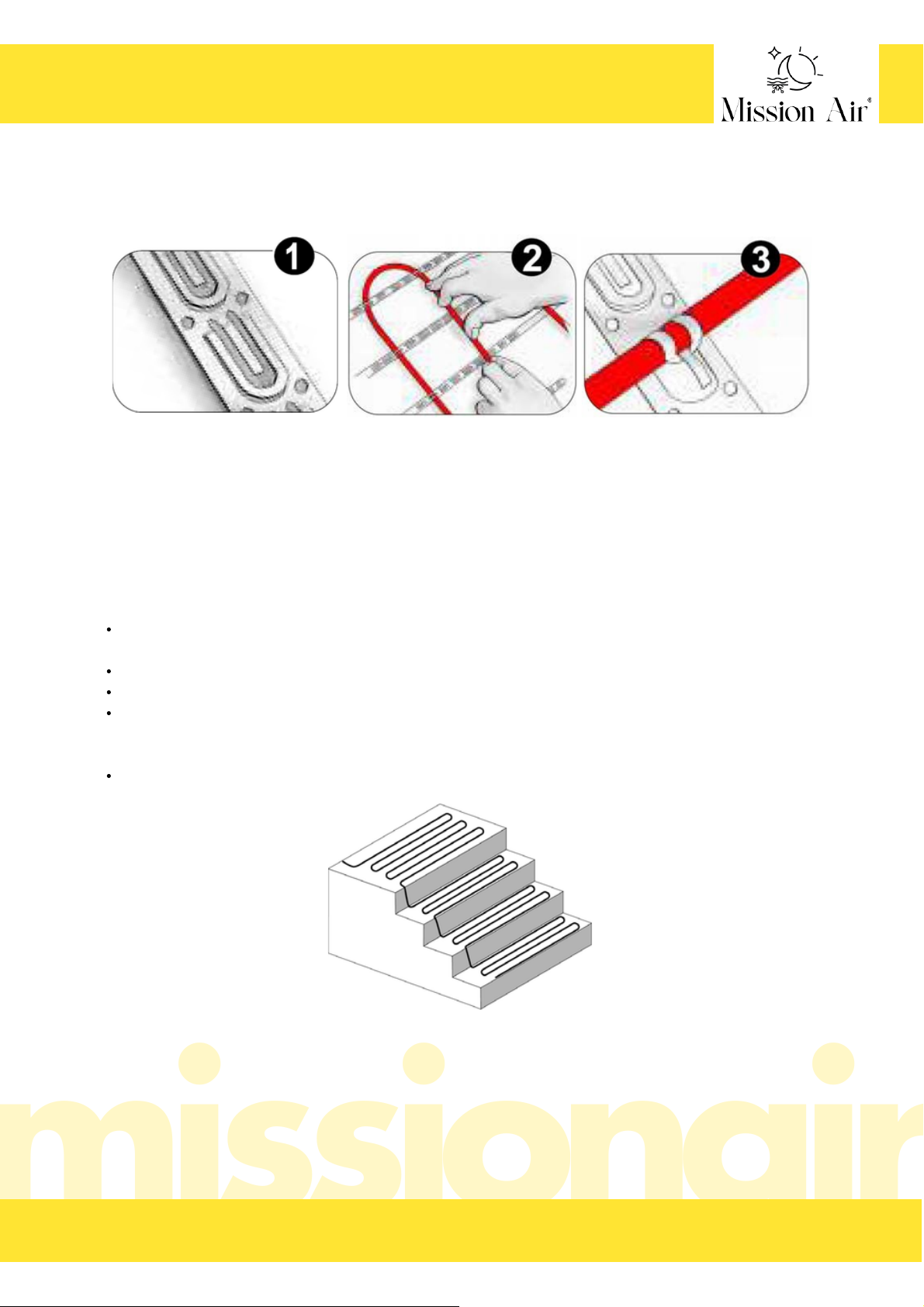
Kable MA ICE-20 można zamontować z wykorzystaniem specjalistycznych taśm kablowych, które ułatwiają
rozmieszczenie systemu.
1. Przymocuj taśmę kablową do powierzchni podłoża (w odległości ok. 10 cm).
2. Umieść kabel MA ICE-20
3. Przypnij kabel do taśmy
Ułóż kabel w odległości nie większej niż 10 cm od przedniej krawędzi stopnia. W przeciwnym razie
krawędź ta może nie topnieć prawidłowo.
Ułóż kabel w odległości nie mniejszej niż 20 cm od bocznych krawędzi gotowego stopnia.
Należy wziąć pod uwagę przyszłe poręcze,
Unikaj zaciskania lub gwałtownego zginania kabla. W narożniku pionu i stopnia należy zachować co
najmniej 38 mm promienia zagięcia, ale zamocować go na tyle płasko, aby beton lub kostka brukowa
nie przygniotły kabla.
Nie instaluj kabla na lub pod schodami takimi jak drewniane lub kompozytowe.
MONTAŻ NA SCHODACH
Przymocuj pojedynczy odcinek przewodu do boku pionu. W razie potrzeby ułóż 3 lub 4 odcinki kabla na
stopniach i kontynuuj w górę każdego z nich. Postępuj zgodnie z poniższymi wskazówkami:
B I U R O @ M I S S I O N A I R . P L S E R W I S @ M I S S I O N A I R . P L W W W . M I S S I O N A I R . P LT E L . ( + 4 8 ) 7 9 7 4 5 1 1 1 1
INSTRUKCJA OBSŁUGI PRZEWODU MA ICE-20
10
P L
Page 11
ZŁĄCZA KOMPENSACYJNE
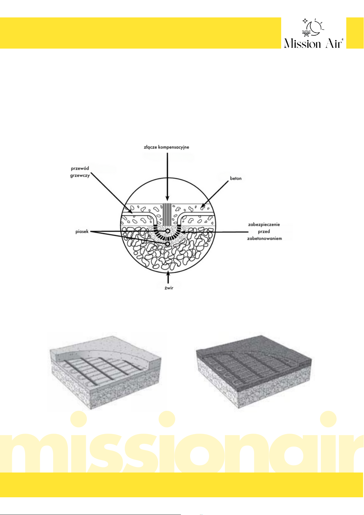
Przewód grzejny MA ICE-20 nigdy nie może być prowadzony przez szczelinę dylatacyjną. Może to
spowodować uszkodzenie kabla podczas ruchu płyty. Zaleca się układanie kabla w taki sposób, aby
uniknąć takich połączeń.
Jeśli jednak jest to konieczne, część kabla grzejnego może zostać wpuszczona w podłoże poniżej szczeliny
dylatacyjnej, jak pokazano na rysunku. Wypełnij przestrzeń wokół kabla warstwą piasku o grubości co
najmniej 2 cm. Pętla kabla grzejnego powinna być wystarczająco długa, aby umożliwić zginanie i nie może
być zatopiona w betonie (piasek powinien przed tym chronić), ponieważ nie pozwoli to na zginanie kabla
wraz z ruchem płyt.
Kable MA ICE-20 mogą być instalowane w różnych systemach wykończeniowych:
Kabel MA ICE-20 w betonie Kabel MA ICE-20 w asfalcie
B IU RO @M IS SI ON AI R. PL S ER WI S@ MI SS IO NA IR .P L W WW .M IS SI ON AI R. PLT EL . (+ 48 ) 79 7 45 1 11 1
INSTRUKCJA OBSŁUGI PRZEWODU MA ICE-20
11
P L
Page 12
Kabel MA ICE-20 pod kostką brukową Kabel MA ICE-20 pod płytką
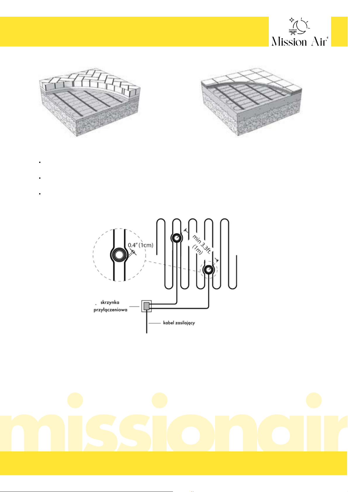
Czujnik musi być umieszczony w obrębie ogrzewanego obszaru i co najmniej 1 m od krawędzi obszaru,
jeśli to możliwe.
Czujnik musi być umieszczony pomiędzy przewodami grzejnymi - należy zachować odległość co
najmniej 1cm pomiędzy rurką czujnika, a przewodem grzejnym.
Pomiędzy dwoma czujnikami musi być zachowana odległość co najmniej 1 m.
Umieszczenie poszczególnych czujników gruntowych
B IU RO @M IS SI ON AI R. PL S ER WI S@ MI SS IO NA IR .P L W WW .M IS SI ON AI R. PLT EL . (+ 48 ) 79 7 45 1 11 1
INSTRUKCJA OBSŁUGI PRZEWODU MA ICE-20
12
P L
Page 13

Określ ogólne obszary, w których chcesz zainstalować kabel grzewczy.
kabla nie można układać w odległości mniejszej niż 15 cm od krawędzi płyt. W przypadku asfaltu jest
to zwiększone do 30 cm od krawędzi w przypadku braku krawężnika,
należy unikać przekraczania szczelin dylatacyjnych w płycie, chyba że zastosowano odpowiednią
technikę kompensacji i kroki zabezpieczające opisane we wcześniejszej części instrukcji,
unikaj umieszczania kabla grzejnego bliżej niż 5 cm od innych elementów, takich jak kable podziemne
lub rury, aby zapobiec ich przegrzaniu,
należy pozostawić co najmniej 5 cm odstępu między sąsiednimi kablami, ale nie więcej niż 10 cm
między sąsiednimi kablami,
kabel musi być ułożony w taki sposób, aby na powierzchni nie znajdowały się inne przeszkody, które
wychwytywałyby ciepło lub umożliwiały potencjalne uszkodzenie, jak np.: wsporniki montażowe, śruby
itp. Należy również wziąć pod uwagę następujące środki ostrożności:
przewód musi być całkowicie zatopiony w betonie, piasku lub asfalcie. Nigdy nie próbuj zużywać
nadmiaru kabla grzejnego w otaczającej glebie, ścianach lub innych niezabezpieczonych
zastosowaniach,
nigdy nie nakładaj przewodu grzejnego na siebie ani nie umieszczaj przewodu grzejnego bliżej niż
5 cm od innego przewodu grzejnego lub zasilającego,
tylko przewód zasilający może wychodzić poza obszar grzewczy. Zostanie on przeciągnięty przez
peszel ochronny w celu jego zabezpieczenia aż do skrzynki przyłączeniowej. NIGDY nie należy
przeciągać przewodu grzejnego, ani fabrycznych złączy do jakiegokolwiek kanału kablowego.
INSTALACJA PRZEWODU GRZEJNEGO
1.
Zastosowania obejmują podjazdy, chodniki, patia, stałe rampy, murowane stopnie i ławki, doki
transportowe, przy drzwiach garażowych i inne. Można je stosować w dowolnym miejscu na zewnątrz w
lokalizacjach mieszkalnych lub komercyjnych, w których gromadzi się śnieg lub lód, o ile kabel jest
całkowicie osadzony w betonie, piasku, grubej zaprawie lub asfalcie.
Kabel nie może być instalowany w pomieszczeniach, w lokalizacjach przemysłowych lub obszarach o
niebezpiecznych klasyfikacjach. Nie należy instalować kabla na lub pod niemurowanymi schodami lub
pokładach, takich jak konstrukcje drewniane lub kompozytowe.
W przypadku instalacji kabla pod kostką brukową, zalecamy zainstalowanie kabli pod całym obszarem.
Wynika to z faktu, że do nieogrzewanego obszaru dostanie się woda roztopowa, która może ponownie
zamarznąć pod kostką brukową, powodując falowanie kostki brukowej w nieogrzewanym obszarze i
docelowe uszkodzenia całej konstrukcji.
2. Wykonaj rysunek wraz z wymiarami we skazanym w instrukcji miejscu i zmierz obszar, na którym ma
zostać zastosowany system.
Wyeliminuj te obszary, w których nie można zainstalować kabla, pamiętając o następujących przeszkodach
i dodatkach:
B IU RO @M IS SI ON AI R. PL S ER WI S@ MI SS IO NA IR .P L W WW .M IS SI ON AI R. PLT EL . (+ 48 ) 79 7 45 1 11 1
INSTRUKCJA OBSŁUGI PRZEWODU MA ICE-20
13
P L
Page 14
kabel i jego sterowanie muszą być podłączone do dedykowanego zasilania z panelu wyłącznika
automatycznego,
kabel jest rezystancyjnym systemem grzewczym i powinien być traktowany jako obciążenie ciągłe dla
celów doboru wielkości obwodu,
wyłącznik automatyczny musi otworzyć wszystkie nieuziemione przewody w tym samym czasie. Do
bezpośredniej ochrony kabla wymagany jest wyłącznik GFCI (zwykle klasy B, wyzwalanie 30 mA),
rozmiar wyłącznika i okablowanie obwodu powinny być zaprojektowane na 125 procent obciążenia
systemu:
należy przestrzegać lokalnych przepisów i wytycznych dotyczących okablowania obwodów
odgałęzionych, przewodów i skrzynek przyłączeniowych. Zewnętrzne i podziemne skrzynki
przyłączeniowe i przewody muszą spełniać wymagania dotyczące szczelności na deszcz lub
wodoszczelności.
Ostrzeżenie
PRZEWODU GRZEJNEGO NIE MOŻNA PRZYCINAĆ NA ODPOWIEDNIĄ DŁUGOŚĆ. Należy zamówić
przewód o odpowiednim rozmiarze. Modyfikowanie przewodu grzejnego jest niedozwolone i może
prowadzić do przegrzania, uszkodzenia i pożaru.
3. Określ miejsca, w którym można umieścić skrzynki przyłączeniowe
Jest to ważne, aby upewnić się, że wybrany kabel prawidłowo wypełnia obszar i ma najlepsze lokalizacje
połączeń. Najlepiej jest umieścić skrzynki przyłączeniowe na ścianie w pomieszczeniu i w odległości od
przewodów zasilających na kablu. Kabel grzewczy jest standardowo wyposażony w przewody zasilające o
długości 3 m.
Jeśli skrzynka przyłączeniowa musi być umieszczona na zewnątrz, zaleca się, aby była zainstalowana
powyżej poziomu gruntu i posiadała odpowiednią odporność na warunki atmosferyczne do użytku na
zewnątrz.
4. Skonsultuj się z elektrykiem, aby upewnić się, że wybrane kable, sterowanie i konstrukcja będą działać
prawidłowo.
◦ Obwód 20 A dla obciążenia do 16 A
◦ Obwód 30 A dla obciążenia do 24 A
◦ Obwód 40 A dla obciążenia do 32 A
◦ Obwód 50 A dla obciążenia do 40 A
◦ Obwód 70 A dla obciążenia do 50 A
5. Sprawdź wszystkie elementy przed instalacją.
Wyjmij kabel z opakowania. Sprawdź go pod kątem widocznych uszkodzeń i upewnij się, że wszystkie
elementy mają prawidłowy rozmiar i typ zgodnie z planem i zamówieniem. Nie próbuj instalować
uszkodzonego produktu.
Zapisz informacje dotyczące kabla w tabeli przy karcie gwarancyjnej.
WAŻNE
Przed instalacją należy w pełni sprawdzić produkty i dokładnie zaplanować miejsce instalacji. Rzeczowa
dyskusja ze wszystkimi zaangażowanymi stronami pomoże wyeliminować kosztowne błędy i uszkodzenia.
B IU RO @M IS SI ON AI R. PL S ER WI S@ MI SS IO NA IR .P L W WW .M IS SI ON AI R. PLT EL . (+ 48 ) 79 7 45 1 11 1
INSTRUKCJA OBSŁUGI PRZEWODU MA ICE-20
14
P L
Page 15

Za pomocą cyfrowego multimetru zmierz rezystancję między przewodami zasilania. Nieprawidłowy
wynik może być spowodowany również niską temperaturą powietrza lub kalibracją miernika.
Odchylenia +/-10% mogą być naturalnym zjawiskiem i są dopuszczalne.
Rezystancja między przewodami, a przewodem uziemiającym powinna być "otwarta", zwykle
wskazywana przez "OL" lub cokolwiek innego, co pokazuje miernik, gdy przewody testowe niczego nie
dotykają. Jeśli odczyt ulegnie zmianie, należy zapisać tę informację i skontaktować się z producentem
przed instalacją. Może to wskazywać na uszkodzenie, problemy z przewodami pomiarowymi lub inne
problemy.
6. Pomiar rezystancji.
7. Przygotowanie materiału bazowego
Przygotuj miejsce, które chcesz ogrzać za pomocą kabla. Obejmuje to upewnienie się, że uwzględniono
wszystkie media i przeszkody. Ułóż gładką, dobrze zagęszczoną podstawę żwirową. Zapewnij
odpowiednie nachylenie i drenaż, aby uniknąć gromadzenia się wody w ogrzewanych lub otaczających
obszarach. Jest to szczególnie ważne w przypadku nawierzchni z kostki brukowej, ponieważ roztopiona
woda może ponownie zamarznąć i podnieść otaczający piasek i nawierzchnię z kostki brukowej. Postępuj
zgodnie z lokalnymi przepisami budowlanymi i wytycznymi konstrukcyjnymi dotyczącymi grubości i rodzaju
podłoża.
Upewnij się, że uwzględniono całkowitą grubość podłoża i płyty wymaganą dla ruchu pieszego i kołowego.
Jeśli kabel ma zostać umieszczony na istniejącej nawierzchni, należy upewnić się, że jest ona sprawdzona
pod kątem obecności ostrych przedmiotów, luźnych odcinków lub innych potencjalnie szkodliwych
elementów, które mogą powodować późniejsze problemy. Bardzo ważne jest, aby kabel był całkowicie
zatopiony.
B IU RO @M IS SI ON AI R. PL S ER WI S@ MI SS IO NA IR .P L W WW .M IS SI ON AI R. PLT EL . (+ 48 ) 79 7 45 1 11 1
8. Przygotowanie do instalacji
Określ czas montażu kabla, gdy sprzęt, ciężkie narzędzia
i ruch na placu budowy będą minimalne, aby zapobiec
ewentualnemu uszkodzeniu produktu. Należy przygotować
się do nałożenia warstw nawierzchni na kabel tego
samego dnia, aby zabezpieczyć je przed uszkodzeniem.
W przypadku instalacji kabla w górnej warstwie
dwuetapowej płyty betonowej lub górnej warstwie
aplikacji asfaltowej, mata lub kabel powinny być
całkowicie gotowe do drugiego etapu. Czas pomiędzy
kolejnymi etapami jest ograniczony, ponieważ płyta nie
powinna w pełni stwardnieć, a asfalt całkowicie ostygnąć.
Jeśli w tej drugiej warstwie zostanie zainstalowany czujnik
płyty, należy zaplanować to z wyprzedzeniem, aby nie
spowodować zbytniego utwardzenia lub ochłodzenia
pierwszej warstwy.
Sprawdź obszar i usuń wszelkie ostre przedmioty.
Instalować w temperaturze co najmniej 5 ℃.
INSTRUKCJA OBSŁUGI PRZEWODU MA ICE-20
15
P L
Page 16

Kabel nie może być układany bliżej niż 15 cm od krawędzi płyt. W przypadku asfaltu odległość ta
wzrasta do 30 cm od krawędzi, jeśli nie ma krawężnika.
Należy unikać przekraczania szczelin dylatacyjnych w płycie, chyba że zastosowano odpowiednią
technikę i kroki zabezpieczające opisane wcześniej.
Unikaj umieszczania kabla grzejnego bliżej niż 5 cm od innych elementów, takich jak kable podziemne
lub rury, aby zapobiec ich przegrzaniu.
Nie zginaj wielokrotnie przewodu grzejnego i nigdy nie zginaj fabrycznych połączeń.
Umieść przewody zasilające kabla obok przepustu kablowego. Elektryk przeciągnie je później przez
kanał kablowy. Upewnij się, że jest on umieszczony w taki sposób, aby żadna część złącza lub kabla
grzejnego nie została wciągnięta do kanału.
WAŻNE
Tego przewodu grzejnego NIE MOŻNA skrócić w celu dopasowania! Nie nakładać na siebie ani nie
krzyżować przewodu grzejnego. Nie należy umieszczać kabla grzejnego bliżej niż 5 cm.
Ostrzeżenie
Przewód grzejny i fabryczne połączenia kabla muszą być całkowicie zatopione w betonie, piasku lub
asfalcie. Nigdy nie próbuj zużywać nadmiaru kabla grzejnego w otaczającej glebie, ścianach lub innych
niezabezpieczonych zastosowaniach.
9. Instalacja kabla
A) aplikacja w betonie
Krok 1: Przymocuj zbrojenie, takie jak siatka druciana lub pręty zbrojeniowe, nad podstawą około 5 cm
poniżej poziomu górnej powierzchni. Kable zostaną później przymocowane do tego wzmocnienia. Bardzo
ważne jest, aby kabel był całkowicie zatopiony w betonie.
Zabezpiecz lub usuń ostre występy, zginając je, przykrywając lub przycinając. Ostre krawędzie mogą
uszkodzić kabel grzejny.
Krok 2: Rozpocznij mocowanie kabla grzejnego w żądanych odstępach do siatki zbrojeniowej lub prętów
zbrojeniowych za pomocą opasek kablowych. Opaski kablowe należy zakładać na końcach każdego
odcinka i co ok. 1 m. Końce opasek kablowych należy skierować w dół lub przyciąć tak, aby nie wystawały
przez warstwy powierzchniowe. Nie używaj metalowych opasek, ponieważ mogą one uszkodzić kabel.
Opaski muszą być przystosowane do podwyższonej temperatury.
W przypadku instalacji na istniejącej płycie, przymocuj taśmy kablowe do powierzchni. Użyj gwoździ lub
podobnych elementów co 15 - 30 cm. Montażowe taśmy kablowe powinny być umieszczony na obu
końcach ogrzewanego obszaru, a dodatkowe paski powinny być stosowane co ok. 1 m pomiędzy nimi, aby
utrzymać kabel w miejscu podczas układania nawierzchni.
Krok 3: Użyj cyfrowego multimetru, aby ponownie zmierzyć rezystancję między przewodami zasilającymi
kabla. Zapisz wyniki w tabeli przy karcie gwarancyjnej.
B IU RO @M IS SI ON AI R. PL S ER WI S@ MI SS IO NA IR .P L W WW .M IS SI ON AI R. PLT EL . (+ 48 ) 79 7 45 1 11 1
INSTRUKCJA OBSŁUGI PRZEWODU MA ICE-20
16
P L
Page 17

Krok 4: Przeprowadź przewody zasilające przez kanał kablowy do skrzynki przyłączeniowej,
pozostawiając co najmniej 15cm wolnej długości przewodu. Zabezpiecz przewód grzejny i splot, aby nie
zostały wciągnięte do kanału. Umieść dużą ilość uszczelniacza do przewodów elektrycznych na końcu
przewodu wokół przewodów zasilających, aby zapobiec przedostawaniu się wody.
Krok 5: Jeśli instalowany jest czujnik płytkowy, umieść gniazdo czujnika zgodnie z instrukcjami.
Krok 6: Zrób zdjęcie instalacji kabla. Może to być bardzo pomocne w późniejszym czasie w przypadku
prac komunalnych, zmian w miejscu instalacji itp. w celu uniknięcia ewentualnych uszkodzeń. Zachowaj
zdjęcia wraz z niniejszą instrukcją instalacji.
Krok 7: Przed rozpoczęciem dalszej pracy sprawdź kabel pod kątem uszkodzeń i zabezpiecz kabel, który
mógł się poluzować.
Krok 8: Wylej beton na podstawę i kabel tak, aby nie mniej niż 3,5cm i nie więcej niż 8cm pokrywały
górną część kabli grzejnych. Łączna grubość płyty powinna wynosić co najmniej 10cm. Należy
przestrzegać wymagań i lokalnych przepisów budowlanych dotyczących wymaganej grubości
Krok 9: Po wyschęciu wartswy betonu, użyj cyfrowego multimetru, aby ponownie zmierzyć rezystancję
między przewodami zasilania kabla. Zapisz wyniki w tabeli przy karcie gwarancyjnej.
WAŻNE
Należy przygotować się do zainstalowania tabliczki znamionowej lub innego oznaczenia wskazującego na
obecność systemu grzewczego. Należy zainstalować tabliczkę znacznikową w miejscu dobrze widocznym.
Nie należy używać ostrych narzędzi, które mogłyby uszkodzić kabel. Upewnij się, że przewód grzejny jest
całkowicie zatopiony. Pozostawić beton do pełnego utwardzenia zgodnie z wymaganiami dostawcy betonu.
Nie podłączaj kabla do zasilania, z wyjątkiem krótkiego testu, ponieważ mogłoby to nieprawidłowo
przyspieszyć utwardzanie i potencjalnie spowodować uszkodzenie betonu.
B IU RO @M IS SI ON AI R. PL S ER WI S@ MI SS IO NA IR .P L W WW .M IS SI ON AI R. PLT EL . (+ 48 ) 79 7 45 1 11 1
INSTRUKCJA OBSŁUGI PRZEWODU MA ICE-20
17
P L
Page 18

B) Aplikacja w asfalcie
Krok 1: Nałożyć pierwszą warstwę na podłoże żwirowe i zagęścić. Kabel MA ICE-20 zostanie później
przymocowana do górnej części. Przed zainstalowaniem kabla pozwól ostygnąć podłożu na tyle, aby
można było na nim bezpiecznie pracować.
Krok 2: Rozpocznij układanie przewodu grzewczego na powierzchni. Możesz w tym celu użyć
montażowych taśm kablowych. Przymocuj taśmy kablowe do powierzchni. Użyj gwoździ lub podobnych
elementów co 15 - 30 cm. Montażowe taśmy kablowe powinny być umieszczony na obu końcach
ogrzewanego obszaru, a dodatkowe paski powinny być stosowane co ok. 1 m pomiędzy nimi, aby
utrzymać kabel w miejscu podczas układania nawierzchni.
Krok 3: Użyj cyfrowego multimetru, aby ponownie zmierzyć rezystancję między przewodami zasilającymi
kabla. Zapisz wyniki w tabeli przy karcie gwarancyjnej.
Krok 4: Przeprowadź przewody zasilające przez kanał kablowy do skrzynki przyłączeniowej,
pozostawiając co najmniej 15cm wolnej długości przewodu. Zabezpiecz przewód grzejny i splot, aby nie
zostały wciągnięte do kanału. Umieść dużą ilość uszczelniacza do przewodów elektrycznych na końcu
przewodu wokół przewodów zasilających, aby zapobiec przedostawaniu się wody.
Krok 5: Jeśli instalowany jest czujnik płytkowy, umieść gniazdo czujnika zgodnie z instrukcjami.
Krok 6: Zrób zdjęcie instalacji kabla. Może to być bardzo pomocne w późniejszym czasie w przypadku
prac komunalnych, zmian w miejscu instalacji itp. w celu uniknięcia ewentualnych uszkodzeń. Zachowaj
zdjęcia wraz z niniejszą instrukcją instalacji.
Krok 7: Przed rozpoczęciem dalszej pracy sprawdź kabel pod kątem uszkodzeń i zabezpiecz kabel, który
mógł się poluzować.
Krok 8: W razie potrzeby nałóż warstwę gruntującą na pierwszą warstwę lub nieobrobioną podstawę na
wierzchu kabla.
Użyj kruszywa 1/2” lub mniejszego. Większe kruszywo może przeciąć lub ścisnąć kabel.
Przed nałożeniem upewnij się, że temperatura asfaltu nie przekracza 285 ℉ (140 ℃). Dobre zagęszczenie
asfaltu wymaga pewnego zakresu temperatur układania, w zależności od rodzaju układanego asfaltu.
Ręcznie połóż asfalt na tym obszarze. Nie stosować ciężkich maszyn do asfaltu, ponieważ mogą one
uszkodzić kabel.
Rozłóż asfalt tak, aby nie mniej niż 3,5cm i nie więcej niż 8cm przykryło górną część kabli grzejnych.
Zagęścić asfalt dowolnym walcem mechanicznym zgodnie z zaleceniami. Jeśli to możliwe, przesuń rolkę
prostopadle do kierunku kabla, aby uniknąć naprężenia kabla poniżej. Uważaj, aby nie zatrzymać ani nie
uruchomić walca nad systemem, ponieważ może to spowodować przesuwanie się asfaltu i potencjalne
uszkodzenie kabli. Upewnij się, że cały kabel grzewczy jest zatopiony.
B IU RO @M IS SI ON AI R. PL S ER WI S@ MI SS IO NA IR .P L W WW .M IS SI ON AI R. PLT EL . (+ 48 ) 79 7 45 1 11 1
INSTRUKCJA OBSŁUGI PRZEWODU MA ICE-20
18
P L
Page 19

Krok 9: Po wyschęciu wartswy asfaltu, użyj cyfrowego multimetru, aby ponownie zmierzyć rezystancję między
przewodami zasilania kabla. Zapisz wyniki w tabeli przy karcie gwarancyjnej.
WAŻNE
Należy przygotować się do zainstalowania tabliczki znamionowej lub innego oznaczenia wskazującego na
obecność systemu grzewczego. Należy zainstalować tabliczkę znacznikową w miejscu dobrze widocznym.
Nie należy używać ostrych narzędzi, które mogłyby uszkodzić kabel. Upewnij się, że przewód grzejny jest
całkowicie zatopiony. Pozostawić asfalt do pełnego utwardzenia zgodnie z wymaganiami dostawcy asfaltu.
Nie podłączaj kabla do zasilania, z wyjątkiem krótkiego testu, ponieważ mogłoby to nieprawidłowo
przyspieszyć utwardzanie i potencjalnie spowodować uszkodzenie asfaltu.
C) Aplikacja kamienia lub kostki brukowej
Krok 1: Postępuj zgodnie z wytycznymi zalecanymi przez producenta kostki brukowej. Jeśli na podłoże
żwirowe ma zostać nałożona gruba warstwa piasku, kabel należy najpierw zamocować na miejscu, a
następnie przykryć warstwą piasku o grubości co najmniej 3,5cm w celu całkowitego osadzenia.
Krok 2: Przymocuj plastikowe opaski kablowe do podstawy żwirowej, wbijając długie gwoździe lub podobne
elementy przez główkę opaski. Opaski kablowe należy zakładać na końcu każdego odcinka i co ok1m. Nie
używaj metalowych opasek kablowych, ponieważ mogą one uszkodzić kabel.
Ułóż kabel i zabezpiecz go opaskami kablowymi.
Krok 3: Użyj cyfrowego multimetru, aby ponownie zmierzyć rezystancję między przewodami zasilającymi
kabla. Zapisz wyniki w tabeli przy karcie gwarancyjnej.
Krok 4: Przeprowadź przewody zasilające przez kanał kablowy do skrzynki przyłączeniowej, pozostawiając
co najmniej 15cm wolnej długości przewodu. Zabezpiecz przewód grzejny i splot, aby nie zostały wciągnięte
do kanału.
Umieść dużą ilość uszczelniacza do przewodów elektrycznych na końcu przewodu wokół przewodów
zasilających, aby zapobiec przedostawaniu się wody.
Krok 5: Jeśli instalowany jest czujnik płytkowy, umieść gniazdo czujnika zgodnie z instrukcjami.
Krok 6: Zrób zdjęcie instalacji kabla. Może to być bardzo pomocne w późniejszym czasie w przypadku prac
komunalnych, zmian w miejscu instalacji itp. w celu uniknięcia ewentualnych uszkodzeń. Zachowaj zdjęcia
wraz z niniejszą instrukcją instalacji.
Krok 7: Przed rozpoczęciem pracy sprawdź kabel pod kątem uszkodzeń i zabezpiecz kabel, który mógł się
poluzować.
B IU RO @M IS SI ON AI R. PL S ER WI S@ MI SS IO NA IR .P L W WW .M IS SI ON AI R. PLT EL . (+ 48 ) 79 7 45 1 11 1
INSTRUKCJA OBSŁUGI PRZEWODU MA ICE-20
19
P L
Page 20

Krok 8: Ręcznie rozsyp piasek na wierzchu kabli i podstawy, tak aby nie mniej niż 3,5cm pokrywało
wierzch kabli grzejnych. Uważaj, aby nie używać ostrych narzędzi.
Zagęść piasek zgodnie z zaleceniami dostawcy kostki brukowej, uważając, aby nie odkryć żadnej żyły
kabla i nie uszkodzić przewodów. Użyj ręcznych narzędzi do zagęszczania wokół obszaru przewodów. W
razie potrzeby dodaj więcej piasku, aby zachować minimum 3,5cm nad wszystkimi kablami i przewodami.
Ułóż kostkę brukową na wierzchu i wykończ zgodnie z wymaganiami.
Krok 9: Użyj cyfrowego multimetru, aby ponownie zmierzyć rezystancję między przewodami zasilającymi
kabla. Zapisz wyniki w tabeli przy karcie gwarancyjnej.
WAŻNE
Zaleca się, aby grubość kostki brukowej nie przekraczała 8cm
Należy przygotować się do zainstalowania tabliczki znamionowej lub innego oznaczenia wskazującego na
obecność systemu grzewczego. Należy zainstalować tabliczkę znacznikową w miejscu dobrze widocznym.
Nie należy używać ostrych narzędzi, które mogłyby uszkodzić kabel. Upewnij się, że przewód grzejny jest
całkowicie zakryty.
D) zastosowanie płytek ceramicznych lub kamiennych
Krok 1: kable mogą być instalowane w płycie konstrukcyjnej lub w grubej warstwie zaprawy nad płytą
konstrukcyjną
Krok 2 Przymocuj plastikowe opaski kablowe do podstawy żwirowej, wbijając długie gwoździe lub
podobne elementy przez główkę opaski. Opaski kablowe powinny być stosowane na końcu każdego
odcinka i co ok 1m. Nie używaj metalowych opasek kablowych, ponieważ mogą one uszkodzić kabel.
Ułóż kabel i zabezpiecz go opaskami kablowymi.
Krok 3: Użyj cyfrowego multimetru, aby ponownie zmierzyć rezystancję między przewodami zasilającymi
kabla. Zapisz wyniki w tabeli przy karcie gwarancyjnej.
Krok 4: Przeprowadź przewody zasilające przez kanał kablowy do skrzynki przyłączeniowej,
pozostawiając co najmniej 15cm wolnej długości przewodu. Zabezpiecz przewód grzejny i splot, aby nie
zostały wciągnięte do kanału.
Umieść dużą ilość uszczelniacza do przewodów elektrycznych na końcu przewodu wokół przewodów
zasilających, aby zapobiec przedostawaniu się wody.
Krok 5: Jeśli instalowany jest czujnik płytkowy, umieść gniazdo czujnika zgodnie z instrukcjami.
Krok 6: Zrób zdjęcie instalacji kabla. Może to być bardzo pomocne w późniejszym czasie w przypadku
prac komunalnych, zmian w miejscu instalacji itp. w celu uniknięcia ewentualnych uszkodzeń. Zachowaj
zdjęcia wraz z niniejszą instrukcją instalacji.
Krok 7: Przed rozpoczęciem pracy sprawdź kabel pod kątem uszkodzeń i zabezpiecz kabel, który mógł się
poluzować.
B IU RO @M IS SI ON AI R. PL S ER WI S@ MI SS IO NA IR .P L W WW .M IS SI ON AI R. PLT EL . (+ 48 ) 79 7 45 1 11 1
INSTRUKCJA OBSŁUGI PRZEWODU MA ICE-20
20
P L
Page 21

Krok 8: W przypadku każdego z poniższych zastosowań należy wybrać i zainstalować materiały klasy
zewnętrznej zgodnie z zaleceniami producenta. Należy stosować wyłącznie płytki szkliste (nieporowate),
ponieważ inne płytki będą wchłaniać wilgoć, co doprowadzi do ich uszkodzenia. Maksymalna grubość
powyżej kabla nie powinna być mniejsza niż 3,5cm i nie większa niż 7cm. Pomiędzy ogrzewanym i
nieogrzewanym obszarem należy zainstalować szczelinę dylatacyjną.
1) Aplikacja zaprawy na sucho lub lateksowo-cementowej (cienkowarstwowej) - w tym zastosowaniu kabel
jest już zainstalowany w płycie betonowej. Podstawową kwestią jest zainstalowanie warstwy wiążącej z
zaprawy cementowej (cienkowarstwowej) i ułożenie płytek.
2) Zastosowanie zaprawy cementowej lub gruboziarnistej - w tym zastosowaniu kabel jest instalowany nad
płytą konstrukcyjną w grubej warstwie zaprawy i warstwie wiążącej. Minimalna warstwa zaprawy 3,2cm
powinna być umieszczona nad kablem. Powyżej tej warstwy układana jest warstwa wiążąca i płytka.
B I U R O @ M I S S I O N A I R . P L S E R W I S @ M I S S I O N A I R . P L W W W . M I S S I O N A I R . P LT E L . ( + 4 8 ) 7 9 7 4 5 1 1 1 1
Przed przystąpieniem do jakichkolwiek prac elektrycznych należy odłączyć napięcie od wszystkich
obwodów zasilających system.
Jeśli instalowany jest czujnik płytowy, należy odsłonić zaślepkę lub uszczelkę wbudowanego gniazda
czujnika. Poprowadź przewody czujnika przez kanał kablowy do sterownika. Zamocuj czujnik w
gnieździe i zakończ instalację zgodnie z wymaganiami producenta czujnika.
Wykonaj połączenia przewodów w skrzynkach połączeniowych dla przewodów zasilających. Jeśli
skrzynka przyłączeniowa znajduje się na zewnątrz, zaleca się użycie nakrętek lub zacisków do
przewodów przeznaczonych do mokrych miejsc, aby uniknąć korozji.
Zainstaluj sterownik w jego lokalizacji zgodnie z instrukcjami dołączonymi do sterownika. Podłącz
przewody do źródła zasilania oraz do przewodów czujnika i przewodów kabla.
Postępuj zgodnie z instrukcjami dotyczącymi sterowania, aby je skonfigurować. Czujnik nie powinien
zezwalać systemowi na zasilanie, dopóki nie zaistnieją odpowiednie warunki.
Krok 9: Użyj cyfrowego multimetru, aby ponownie zmierzyć rezystancję między przewodami zasilającymi
kabla. Zapisz wyniki w tabeli przy karcie gwarancyjnej.
Ważne
Należy przygotować się do zainstalowania tabliczki znamionowej lub innego oznaczenia wskazującego na
obecność systemu grzewczego. Należy zainstalować tabliczkę znacznikową w miejscu dobrze widocznym.
Nie należy używać ostrych narzędzi, które mogłyby uszkodzić kabel. Upewnij się, że przewód grzejny jest
całkowicie zatopiony.
INSTALACJA STEROWNIKÓW I CZUJNIKÓW
WAŻNE
Przewód uziemiający dostarczony z kablem musi być podłączony do odpowiedniego zacisku uziemienia.
Nie należy w pełni zasilać kabla, z wyjątkiem tego krótkiego testu, dopóki beton nie zostanie utwardzony
lub asfalt nie ostygnie. Może to spowodować nieprawidłowe utwardzenie materiałów powierzchniowych.
UWAGA: Z wyjątkiem tego krótkiego testu, nie należy używać systemu przy temperaturze powietrza
powyżej 50 ℉ (10 ℃). Spowoduje to naprężenie materiałów i skróci żywotność kabla grzejnego oraz może
spowodować uszkodzenie materiałów i kabli grzejnych.
INSTRUKCJA OBSŁUGI PRZEWODU MA ICE-20
21
P L
Page 22

WAŻNE
ABY GWARANCJA MIAŁA ZASTOSOWANIE, NALEŻY WYKONAĆ TE TESTY, ZAPISAĆ
WYNIKI NA KARCIE GWARANCYJNEJ I ZACHOWAĆ KOPIĘ ZAPISU.
Ustaw multimetr na zakres 200 lub 2000 omów.
Podłącz przewody multimetru do żył kabla
Porównaj odczyt rezystancji z rezystancją określoną w
tabeli we wcześniejszszej części. Wartość powinna
mieścić się w zakresie ±10%. Jeśli odczyt jest inny,
należy skontaktować się z producentem.
Odczyty należy zapisać w karcie gwarancyjnej.
TEST REZYSTANCJI KABLA GRZEJNEGO
Ten test mierzy rezystancję kabla MA ICE-20 i służy do
określenia integralności obwodu.
Podłącz przewód uziemiający do czarnego przewodu,
a oba przewody zasilające do czerwonego przewodu
multimetru.
Upewnij się, że miernik wskazuje "Open" lub "OL" lub
cokolwiek innego, co miernik pokazuje, gdy przewody
testowe niczego nie dotykają.
Zapisz te odczyty w karcie gwarancyjnej.
TEST REZYSTANCJI IZOLACJI ZA POMOCĄ
MULTIMETRU CYFROWEGO
Ten test zapewnia, że płaszcz izolacyjny kabla nie jest
uszkodzony. Niska wartość wskazuje, że kabel został
uszkodzony i należy go wymienić.
B I U R O @ M I S S I O N A I R . P L S E R W I S @ M I S S I O N A I R . P L W W W . M I S S I O N A I R . P LT E L . ( + 4 8 ) 7 9 7 4 5 1 1 1 1
INSTRUKCJA OBSŁUGI PRZEWODU MA ICE-20
22
P L
Page 23
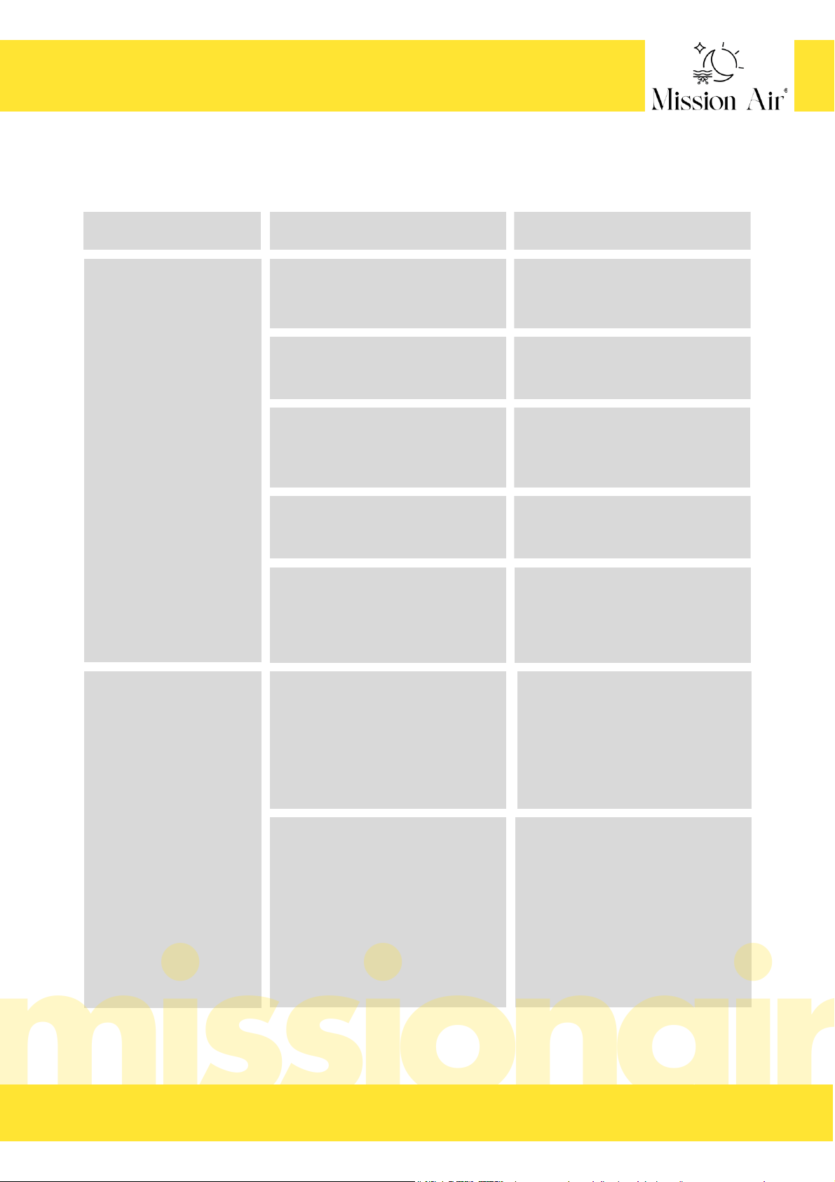
ROZWIĄZYWANIE PROBLEMÓW
W przypadku wystąpienia problemów z systemem należy zapoznać się z poniższym przewodnikiem
rozwiązywania problemów. Wszelkie prace związane z usuwaniem usterek należy wykonywać przy
odłączonym zasilaniu, o ile nie wskazano inaczej.
PROBLEM
MOŻLIWA PRZYCZYNA
ROZWIĄZANIE
Pomiar rezystancji kabla
wykracza poza zakres
podany na tabliczce
znamionowej.
Do pomiaru użyto omomierza
analogowego (z ruchomą igłą).
odczytu.
Kabel zostały uszkodzone.
Jeśli pomiar jest tylko trochę niski lub
wysoki, temperatura powietrza ma wpływ
na rezystancję.
Zmierz rezystancję kabla pomiędzy wszystkimi
przewodami zasilającymi. Jeśli występuje
przerwa lub zwarcie
uszkodzenia, należy zapisać te rezystancje i
skontaktować się z producentem.
Śnieg/lód nie topnieje.
Zastosowano nieprawidłowe napięcie.
Jeśli pomiar wykaże przerwę lub zwarcie,
przewód grzejny jest uszkodzony.
Pomiar rezystancji może pochodzić z
więcej niż jednego kabla.
Omomierz (multimetr) jest ustawiony na
niewłaściwą skalę.
Uzyskaj cyfrowy omomierz (multimetr) z
odczytem od 0 do 20 000 omów (Ω) i
ponownie zmierz rezystancję.
Umieścić kabel w pomieszczeniu o
temperaturze pokojowej i ponownie zmierzyć
po godzinie.
Zanotuj rezystancję pomiędzy wszystkimi
przewodami zasilającymi i skontaktuj się z
producentem.
Odłącz wszystkie kable od siebie i od
elementów sterujących, a następnie dokonaj
ponownych pomiarów.
Jeśli omomierz (multimetr) ma kilka zakresów
(np. 200Ω, 2kΩ, 20kΩ, 200kΩ, 20MΩ), ustaw
zakres na 200Ω i wykonaj
ponownie pomiar.
Na krótko włącz zasilanie systemu i za
pomocą multimetru zmierz napięcie między
przewodami zasilającymi kabla. Sprawdź
wartości znamionowe napięcia dla każdego
sterownika i kabla, aby upewnić się, że są
one zgodne. Jeśli to możliwe, użyj miernika
cęgowego, aby zmierzyć napięcie prądu w
każdym kablu.
B I U R O @ M I S S I O N A I R . P L S E R W I S @ M I S S I O N A I R . P L W W W . M I S S I O N A I R . P LT E L . ( + 4 8 ) 7 9 7 4 5 1 1 1 1
INSTRUKCJA OBSŁUGI PRZEWODU MA ICE-20
23
P L
Page 24

PROBLEM MOŻLIWA PRZYCZYNA ROZWIĄZANIE
Kable są połączone
szeregowo.
System działa w sposób ciągły.
Nieprawidłowe okablowanie. Sterowanie
zostało "ominięte
Wadliwe sterowanie. Przekaźnik nie
otwiera się prawidłowo.
Wiele kabli musi być połączonych
"równolegle".
Sprawdź połączenia przewodów. Patrz
instrukcje dotyczące przewodów dołączone do
sterownika oraz w niniejszej instrukcji.
Sprawdź instrukcje dotyczące sterowania.
Śnieg/lód nie topnieje.
B I U R O @ M I S S I O N A I R . P L S E R W I S @ M I S S I O N A I R . P L W W W . M I S S I O N A I R . P LT E L . ( + 4 8 ) 7 9 7 4 5 1 1 1 1
INSTRUKCJA OBSŁUGI PRZEWODU MA ICE-20
24
P L
Page 25
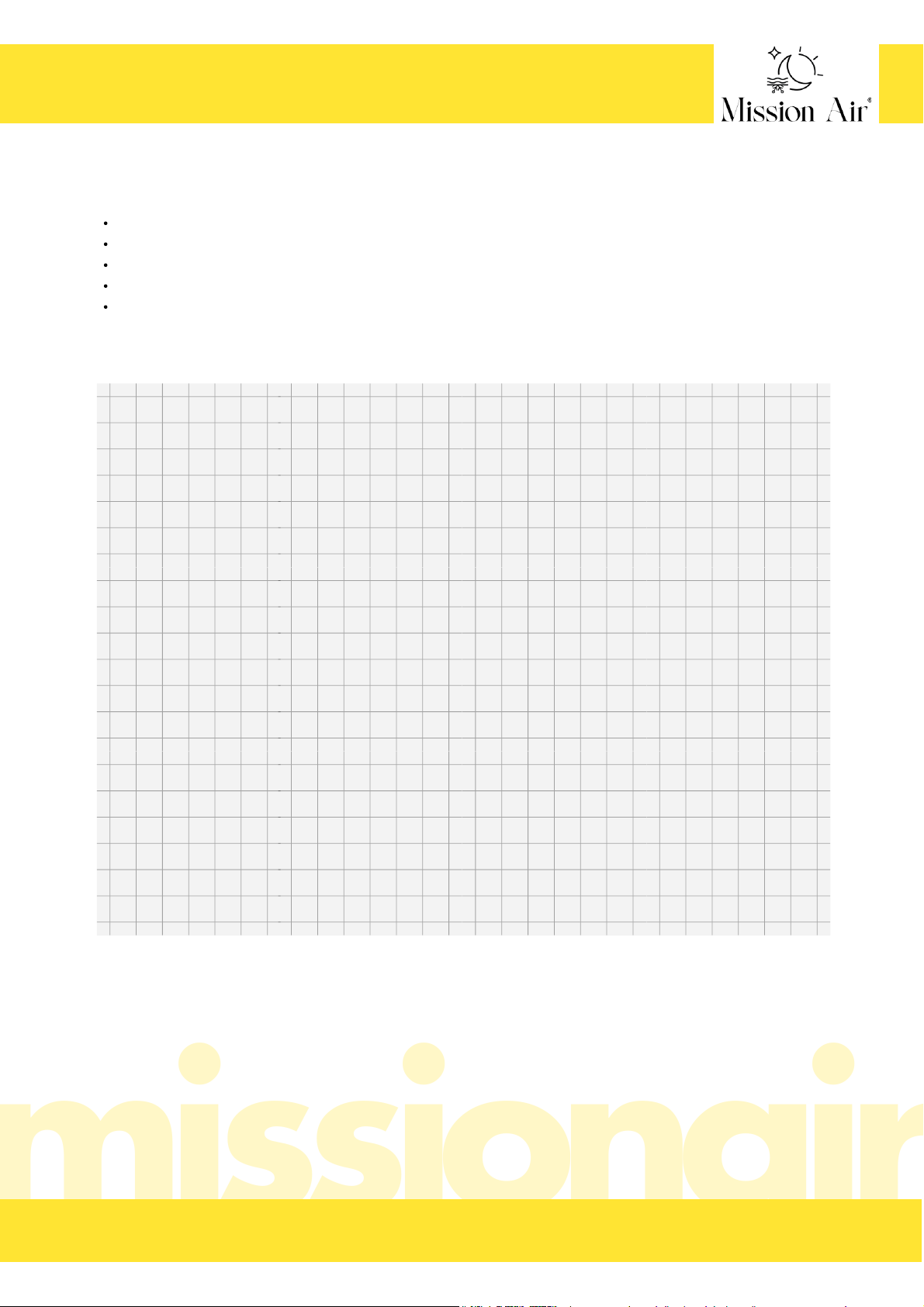
Obrys obszaru grzewczego z wymiarami,
Oznaczenie miejsc występowania stałych zabudowań,
Ułożenie przewodów z oznaczeniem ich długości oraz mocy,
Umiejscowienie systemu sterowania,
Umiejscowienie czujnika temperatury.
PLAN ROZMIESZCZENIA SYSTEMU:
Uwzględnij:
PLAN
D A T A W Y K O N A N I A P R O J E K T U :
B I U R O @ M I S S I O N A I R . P L S E R W I S @ M I S S I O N A I R . P L W W W . M I S S I O N A I R . P LT E L . ( + 4 8 ) 7 9 7 4 5 1 1 1 1
INSTRUKCJA OBSŁUGI PRZEWODU MA ICE-20
25
P L
Page 26

Producent zapewnia 25 - letni okres gwarancyjny produktu, na którym wydana jest niniejsza karta
gwarancyjna licząc od dnia zakupu.
Warunkami obowiązywania pełnego okresu ochrony gwarancyjnej są: dokładne zaznajomienie się z
instrukcją, wykonanie szczegółowego planu instalacji w wyznaczonym w instrukcji miejscu, podłączenie
elektryczne systemu wykonane przez wykwalifikowanego elektryka ze stosownymi i ważnymi
uprawnieniami, , prawidłowe uzupełnienie karty gwarancyjnej. Niespełnienie któregoś z wymienionych
kryteriów jest jednoznaczne z utratą ochrony gwarancyjnej.
Jakakolwiek niezgodność wykonanego projektu ze stanem faktycznym oznacza brak ochrony
gwarancyjnej,
Niniejszą gwarancją objęte są ukryte wady materiałowe, lub konstrukcyjne urządzenia uniemożliwiające
jego użytkowanie zgodnie z przeznaczeniem.
Maksymalne roszczenie gwarancyjne jest równe jednokrotnej wartości zakupu urządzenia
zakwalifikowanego przez Gwaranta do wymiany. Gwarant nie ponosi żadnych dalszych kosztów
spowodowanych wadliwą pracą urządzenia.
Usterki produktu ujawnione w okresie gwarancyjnym będą usuwane bezpłatnie w terminie 30 dni
roboczych, licząc od dnia dostarczenia towaru do siedziby firmy.
Wszelkie zmiany zapisów w Karcie Gwarancyjnej oraz ślady prób dokonania zmian konstrukcyjnych
produktu oraz samodzielnych napraw powodują, że gwarancja przestaje obowiązywać.
Wszelkie wady lub uszkodzenia należy zgłosić Gwarantowi niezwłocznie, nie później jednak niż 7 dni
od daty ich wystąpienia. Użytkowanie systemu po stwierdzeniu jego wady lub zaniechanie zgłoszenia
serwisowego oznacza utratę ochrony gwarancyjnej.
Reklamację zgłaszamy poprzez formularz serwisowy znajdujący się na stronie producenta.
Warunkiem obowiązywania gwarancji oraz wykonania naprawy jest dostarczenie produktu z
podpisaną i prawidłowo uzupełnioną kartą gwarancyjną oraz dowodem zakupu produktu (paragon,
faktura).
Dostarczenie produktu do Gwaranta leży po stronie Kupującego.
Urządzenie należy odpowiednio zapakować i przygotować dla kuriera. Serwis nie ponosi
odpowiedzialności za uszkodzenia w transporcie wynikające z nieodpowiednio zapakowanej przesyłki.
W przypadku niespełnienia któregokolwiek z warunków niniejszej gwarancji towar, w stanie
niezmienionym, zostanie odesłany na koszt kupującego.
Wszelka korespondencja, zwroty, reklamacje, powinny być kierowane na adres serwisu podany na
stronie producenta.
Gwarancja na sprzedany towar konsumpcyjny nie wyłącza, nie ogranicza ani nie zawiesza uprawnień
kupującego wynikających z niezgodności towaru z umową.
Gwarancja nie obejmuje wad powstałych w wyniku:
nieprawidłowego doboru produktu do warunków istniejących w miejscu montażu,
nieprawidłowego użytkowania produktu,
nieprawidłowego, niezgodnego z instrukcją montażu,
działania zdarzeń losowych lub czynników noszących znamiona siły wyższej
B I U R O @ M I S S I O N A I R . P L S E R W I S @ M I S S I O N A I R . P L W W W . M I S S I O N A I R . P LT E L . ( + 4 8 ) 7 9 7 4 5 1 1 1 1
WARUNKI GWARANCJI
26
P L
Page 27

Gwarancja nie obejmuje obniżania się jakości produktu spowodowanego normalnym procesem zużycia
i poniższych przypadków:
mechaniczne uszkodzenia produktu i wywołane nim wady,
uszkodzenia i wady powstałe na skutek:
niewłaściwego lub niezgodnego z instrukcją użytkowania, przechowywania i konserwacji,
samowolnych (dokonanych przez użytkownika lub inne nieupoważnione osoby) napraw,
przeróbek lub zmian konstrukcyjnych,
podłączeniem dodatkowego wyposażenia, innego niż zalecane przez producenta produktu
B I U R O @ M I S S I O N A I R . P L S E R W I S @ M I S S I O N A I R . P L W W W . M I S S I O N A I R . P LT E L . ( + 4 8 ) 7 9 7 4 5 1 1 1 1
WARUNKI GWARANCJI
27
P L
Page 28

The Mission Air® brand's mission is clear - to create modern and
environmentally friendly solutions for your comfort and convenience by
providing zero-emission electric heating and air conditioning products.
As a responsible company, we strive to minimise our impact on the environment by
designing and manufacturing efficient systems that work well with renewable energy
sources and thus reduce emissions of gases that are harmful to our planet.
Concern for the environment is one of our priorities!
www.missionair.pl
ABOUT US
B I U R O @ M I S S I O N A I R . P L S E R W I S @ M I S S I O N A I R . P L W W W . M I S S I O N A I R . P LT E L . ( + 4 8 ) 7 9 7 4 5 1 1 1 1
CABLE MANUAL MA ICE-20
E N
Page 29
B I U R O @ M I S S I O N A I R . P L S E R W I S @ M I S S I O N A I R . P L W W W . M I S S I O N A I R . P LT E L . ( + 4 8 ) 7 9 7 4 5 1 1 1 1
The English manual is is available on our website.
Das Handbuch in deutscher Sprache ist auf unserer Website verfügbar.
This manual is designed specifically for you to, among other things, help
you understand how your MA ICE-20 heating duct system from Mission
Air® works, and consequently how to operate it with maximum efficiency.
The manual will help you to install it safely and answer questions that
may arise during installation.
The instructions should be read and fully understood before installing the system. Incorrect
installation or failure to complete the warranty card and installation plan is tantamount to
loss of warranty protection.
Thank you for your trust and for purchasing our products. We are sure that
the MA ICE-20 heating cables from Mission Air® will guarantee warmth in
any situation.
www.missionair.pl
Посбник українською мовою є на нашому сайт.
CABLE MANUAL MA ICE-20
29
E N
Page 30

PRODUCT DESCRIPTION.............................................................................................................32
SPECIFICATION.....................................................................................................................33-34
WARNINGS..............................................................................................................................35
SELECTED INSTALLATION METHODS.......................................................................................36-38
HEATING CABLE INSTALLATION.............................................................................................39-47
INSTALLATION OF CONTROLS AND SENSORS............................................................................47
INSULATION RESISTANCE TEST WITH DIGITAL MULTIMETER..........................................................48
HEATING CABLE RESISTANCE TEST.............................................................................................48
PROBLEM SOLVING...............................................................................................................49-50
SYSTEM LAYOUT PLAN...............................................................................................................51
WARRANTY CONDITIONS.....................................................................................................52-53
TABLE OF CONTENTS
1.
2.
3.
4.
5.
6.
7.
8.
9.
10.
11.
B I U R O @ M I S S I O N A I R . P L S E R W I S @ M I S S I O N A I R . P L W W W . M I S S I O N A I R . P LT E L . ( + 4 8 ) 7 9 7 4 5 1 1 1 1
CABLE MANUAL MA ICE-20
30
E N
Page 31

WARNING
Risk of electric shock and fire!
If the system is damaged or not installed correctly, a fire or electric shock may occur, resulting in serious
personal injury or damage to property. Carefully observe the warnings and instructions in this manual.
It is important that the system is only installed by qualified electricians who are familiar with the correct
dimensioning, installation, construction and operation of the heating system and the hazards involved. The
installation must comply with all national and local electrical regulations. If you are not familiar with these
requirements, contact a certified electrician.
If the system is damaged, it must be replaced. Do not attempt to connect or repair any part of the system
yourself. Heating cables should not be shortened. The length of the cable should be chosen to suit the specific
installation plan.
The safety and reliability of any heating system depends on its proper design, installation and testing.
Improper installation or mishandling of the product can cause damage to the heating cable, system
components and property, and can create a risk of fire or electric shock. The instructions contained in this
manual are very important. They must be followed carefully to minimise hazards and ensure reliable and safe
operation of the system.
B I U R O @ M I S S I O N A I R . P L S E R W I S @ M I S S I O N A I R . P L W W W . M I S S I O N A I R . P LT E L . ( + 4 8 ) 7 9 7 4 5 1 1 1 1
CABLE MANUAL MA ICE-20
31
E N
Page 32

a permanent solution to problems caused by low temperatures,
improved safety, providing immediate relief from snow and ice,
time savings, by not having to clear snow from pavements, driveways or stairs,
financial savings, by not having to hire companies or machines for snow clearing,
low operating costs,
efficient use of power with appropriate control systems.
ideal for driveways, car parks, pavements, steps, ramps, bridges and many other applications,
for use in concrete, asphalt, cobblestone or stone pavers and ceramic or stone tiles,
single-point connection,
two-wire cable,
quiet, efficient and safe,
does not emit electromagnetic fields (EMF),
easy and flexible installation,
durable construction,
25-year warranty against manufacturing defects.
PRODUCT DESCRIPTION
The MA ICE-20 system is designed to provide anti-freeze and snow protection for external parts of a building,
such as entrances, stairs, walkways, driveways, ramps, etc.
The installation of the system provides many benefits. Amongst these we can mention:
Features of the MA ICE-20 system:
B I U R O @ M I S S I O N A I R . P L S E R W I S @ M I S S I O N A I R . P L W W W . M I S S I O N A I R . P LT E L . ( + 4 8 ) 7 9 7 4 5 1 1 1 1
CABLE MANUAL MA ICE-20
32
E N
Page 33

cut or shorten,
cross with each other and with other cables, e.g. power cables,
laid in such a way that they are in contact with each other.
SPECIFICATION
NOTE!
Heating cables are not allowed under any circumstances:
UNDER NO CIRCUMSTANCES SHOULD CABLES BE INSTALLED
WITHOUT SUPERVISION OF THE CONTROL EQUIPMENT!
CABLE CONSTRUCTION
RATED VOLTAGE
LINEAR POWER
AVAILABLE LENGTHS
MAX. RATED TEMPERATURE
CABLE CROSS-SECTION
BENDING RADIUS
EXTERNAL INSULATION
CABLE INSULATION
SCREENING
POWER CABLE
MIN. INSTALLATION TEMPERATURE
round, double cable with 100% screen
230 V
20 W/m
from 4 m to 195 m
105℃
6 - 6,5 mm
38 mm
XLPE
PVC
PVC
5℃
3 m long
B I U R O @ M I S S I O N A I R . P L S E R W I S @ M I S S I O N A I R . P L W W W . M I S S I O N A I R . P LT E L . ( + 4 8 ) 7 9 7 4 5 1 1 1 1
CABLE MANUAL MA ICE-20
33
E N
Page 34

TYPE
MA ICE-20 4M
MA ICE-20 7,5M
LINEAR POWER
W/M
LENGTH
(M)
A
MA ICE-20 12,5M
20
4
0,4
20
7,5 0,7
20 12,5 1,1
TOTAL POWER
(W)
80
150
250
MA ICE-20 19M
20 19 1,7 380
RESISTANCE (Ω)
661,3
352,7
211,6
139,2
MA ICE-20 25M
MA ICE-20 31M
MA ICE-20 40M
20
25
2,3
20
31 2,8
20 40 3,6
500
620
800
MA ICE-20 50M
20 50 4,5 1000
105,8
85,3
66,1
52,9
MA ICE-20 60M
MA ICE-20 70M
MA ICE-20 85M
20
60
5,5
20
70 6,4
20 85 7,7
1200
1400
1700
MA ICE-20 100M
20 100 9,1 2000
44,1
37,8
31,1
26,5
MA ICE-20 120M
MA ICE-20 135M
MA ICE-20 150M
20
120
10,9
20
135 12,3
20 150 13,6
2400
2700
3000
MA ICE-20 170M
20 170 15,5 3400
22,0
19,6
17,6
15,6
MA ICE-20 195M
20 195 17,7 3900 13,6
B I U R O @ M I S S I O N A I R . P L S E R W I S @ M I S S I O N A I R . P L W W W . M I S S I O N A I R . P LT E L . ( + 4 8 ) 7 9 7 4 5 1 1 1 1
CABLE MANUAL MA ICE-20
34
E N
Page 35

Installation must be carried out by qualified personnel in accordance with local regulations and
standards. Read these important warnings and all installation instructions before proceeding with the
installation. Failure to do so may result in fire, electric shock, property damage, personal injury or even
death;
For outdoor installation only;
Never cut or shorten the heating cable;
Take special care not to damage the MA ICE-20 cables when using sharp tools, wheelbarrows, heavy
machinery and paving equipment, shovels, rakes or other tools. Avoid walking on the cables during
installation;
Installation with a controller that does not include an integrated temperature limiter is not recommended;
MA ICE-20 cables must be embedded in mortar or mortar mix, concrete, sand or similar material;
The supply/heating cable connection and at least 30 cm of the supply cable must be embedded in a
hardened surface;
NEVER pull the heating cable into any duct. The remaining supply cable must be routed through the duct;
If necessary, the supply cable can be extended or shortened, but it should never be disconnected from the
heating cable;
Do not install the MA ICE-20 so that two heating cables touch, cross or overlap, or place a heating cable
closer than 5 cm to another heating cable, power cable, underground cable or pipeline to prevent
overheating and damage;
Always keep the ends of supply cables dry before and during installation.
Remember to always measure, verify and record the actual resistance throughout the installation process:
After removal from the packaging
After installation, but before application of surface material
After the application of the surface material
Make a note of these values in the table next to the warranty conditions, otherwise the warranty will be
invalidated;
Never attempt to repair a damaged cable. Contact your distributor or manufacturer for assistance.
Remember to check that the supply voltage corresponds to the voltage required for the product.
Always disconnect power to all circuits before installing or servicing.
Always provide ground fault circuit interrupter (GFCI) protection for the snow melting system. This
protection may be on the circuit breaker or on the controller.
Always install the unit in accordance with all local regulations and requirements.
WARNINGS
Please read this manual carefully before installing the MA ICE-20 system.
a.
b.
c.
B I U R O @ M I S S I O N A I R . P L S E R W I S @ M I S S I O N A I R . P L W W W . M I S S I O N A I R . P LT E L . ( + 4 8 ) 7 9 7 4 5 1 1 1 1
CABLE MANUAL MA ICE-20
35
E N
Page 36
SELECTED INSTALLATION METHODS
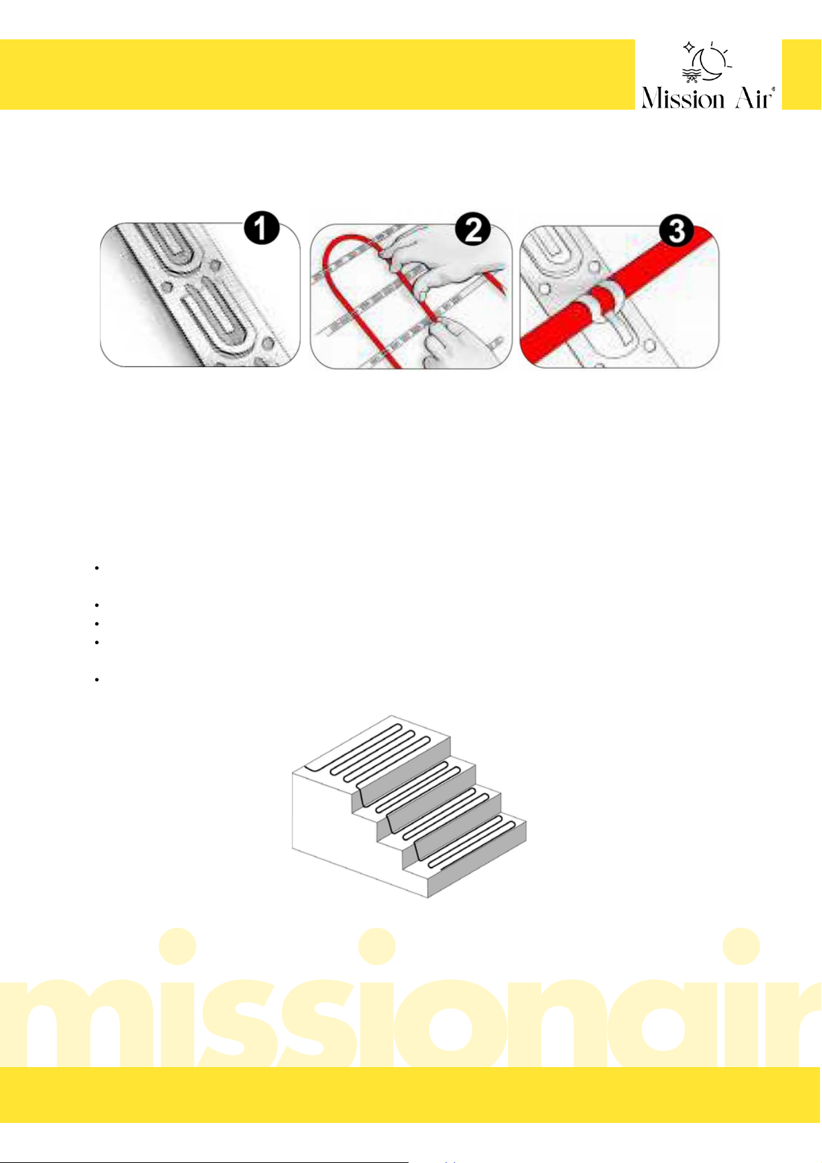
MA ICE-20 cables can be installed using specialised cable tapes to facilitate system deployment.
1. fix the cable tape to the surface of the substrate (at a distance of approx. 10 cm).
2. place the MA ICE-20 cable
3. pin the cable to the tape
Lay the cable no more than 10 cm from the front edge of the step. Otherwise this edge may not melt
properly.
Lay the cable no less than 20 cm from the side edges of the finished step.
Take into account future handrails,
Avoid crimping or bending the cable sharply. At the corner of the riser and step, maintain at least a 38
mm bend radius, but fix it flat enough so that concrete or paving stones do not crush the cable.
Do not install the cable on or under stairs such as wooden or composite stairs.
MOUNTING ON STAIRS
Attach a single section of cable to the side of the riser. If necessary, lay 3 or 4 sections of cable on the steps
and continue up each step. Follow the instructions below:
B I U R O @ M I S S I O N A I R . P L S E R W I S @ M I S S I O N A I R . P L W W W . M I S S I O N A I R . P LT E L . ( + 4 8 ) 7 9 7 4 5 1 1 1 1
CABLE MANUAL MA ICE-20
36
E N
Page 37
EXPANSION JOINTS
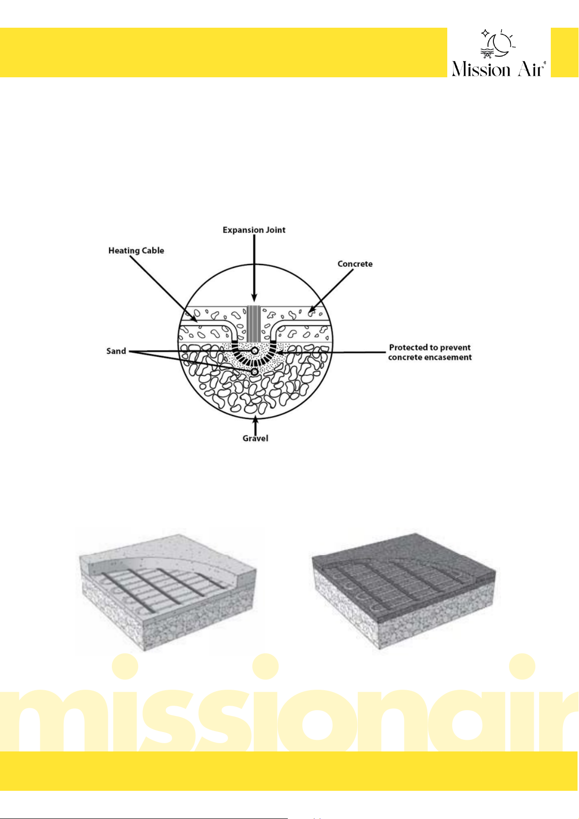
The MA ICE-20 heating cable must never be routed through an expansion joint. This may cause damage to
the cable during panel movement. It is recommended that the cable is laid in such a way as to avoid such
connections.
However, if necessary, part of the heating cable can be recessed into the substrate below the expansion joint
as shown. Fill the space around the cable with a layer of sand at least 2 cm thick. The heating cable loop
should be long enough to allow bending and must not be sunk into the concrete (the sand should protect
against this), as this will not allow the cable to bend with the movement of the slabs.
MA ICE-20 cables can be installed in a variety of finishing systems:
MA ICE-20 cable in concrete MA ICE-20 cable in asphalt
B I U R O @ M I S S I O N A I R . P L S E R W I S @ M I S S I O N A I R . P L W W W . M I S S I O N A I R . P LT E L . ( + 4 8 ) 7 9 7 4 5 1 1 1 1
CABLE MANUAL MA ICE-20
37
E N
Page 38
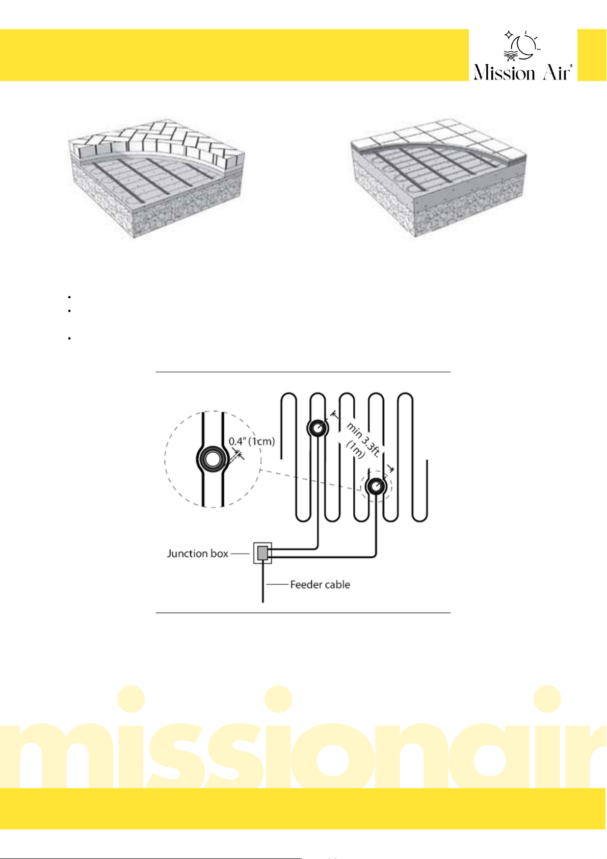
MA ICE-20 cable under paving stones MA ICE-20 cable under tile
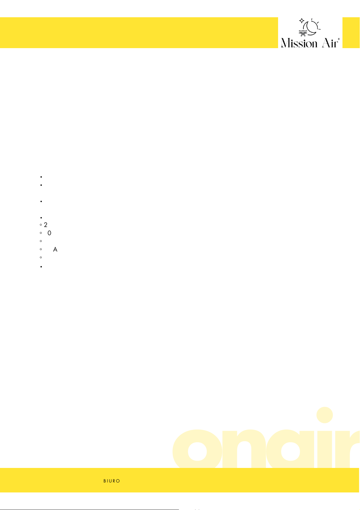
The sensor must be placed within the heated area and at least 1m from the edge of the area if possible.
The sensor must be placed between the heating cables - a distance of at least 1cm must be maintained
between the sensor tube and the heating cable.
A distance of at least 1m must be maintained between two sensors.
Placement of individual ground sensors
B I U R O @ M I S S I O N A I R . P L S E R W I S @ M I S S I O N A I R . P L W W W . M I S S I O N A I R . P LT E L . ( + 4 8 ) 7 9 7 4 5 1 1 1 1
CABLE MANUAL MA ICE-20
38
E N
Page 39

Identify the general areas where you want to install the heating cable.
The cable may not be laid within 15 cm of the edge of the slabs. For asphalt this is increased to 30 cm
from the edge in the absence of a kerb,
avoid crossing the expansion joints in the slab unless the appropriate compensation technique and safety
steps described earlier in this manual have been applied,
avoid placing the heating cable closer than 5 cm to other elements such as underground cables or pipes
to prevent them from overheating,
leave a space of at least 5 cm between adjacent cables, but no more than 10 cm between adjacent
cables,
the cable must be laid in such a way that there are no other obstacles on the surface that would catch the
heat or allow potential damage, such as: mounting brackets, screws, etc. The following precautions must
also be taken into account:
The cable must be completely embedded in concrete, sand or asphalt. Never attempt to use excess
heating cable in surrounding soil, walls or other unprotected applications,
never overlap the heating cable or place the heating cable closer than 5 cm to another heating cable
or power supply cable,
only the supply cable may extend beyond the heating area. It will be pulled through the protective
conduit to protect it up to the junction box. NEVER pull the heating cable or factory connectors into
any cable duct.
HEATING CABLE INSTALLATION
1.
Applications include driveways, walkways, patios, fixed ramps, brick steps and benches, transport docks, at
garage doors and more. They can be used anywhere outdoors in residential or commercial locations where
snow or ice accumulates, as long as the cable is completely embedded in concrete, sand, thick mortar or
asphalt.
The cable must not be installed indoors, in industrial locations or areas with hazardous classifications. Do not
install the cable on or under unwalled stairs or decks such as wooden or composite structures.
If installing the cable under paving, we recommend installing the cables under the entire area. This is because
snowmelt water will enter the unheated area and may re-freeze under the paving stones, causing rippling of
the paving stones in the unheated area and ultimately damaging the entire structure.
2. Make a drawing with dimensions at the location specified in the instructions and measure the area
where the system is to be applied.
Eliminate those areas where the cable cannot be installed, bearing in mind the following obstacles and
additions:
B I U R O @ M I S S I O N A I R . P L S E R W I S @ M I S S I O N A I R . P L W W W . M I S S I O N A I R . P LT E L . ( + 4 8 ) 7 9 7 4 5 1 1 1 1
CABLE MANUAL MA ICE-20
39
E N
Page 40
the cable and its control must be connected to a dedicated power supply from the circuit breaker panel,
the cable is a resistive heating system and should be treated as a continuous load for circuit sizing
purposes,
the circuit breaker must open all ungrounded conductors at the same time. A GFCI circuit breaker
(typically Class B, 30 mA trip) is required for direct cable protection,
circuit breaker sizing and circuit wiring should be designed for 125 per cent of the system load:
Local regulations and guidelines for the wiring of branch circuits, conduits and junction boxes must be
observed. External and underground junction boxes and conduits must meet the requirements for rain
tightness or water tightness.
Warning
THE HEATING CABLE CANNOT BE CUT TO THE CORRECT LENGTH. A cable of the correct size must be
ordered. Modification of the heating cable is not permitted and may lead to overheating, damage and fire.
3. Identify locations where junction boxes can be placed
It is important to make sure that the chosen cable fills the area correctly and has the best connection locations.
It is best to place the junction boxes on the wall in the room and at a distance from the power wires on the
cable. The heating cable comes with 3 m of power cables as standard.
If the junction box has to be placed outside, it is recommended that it is installed above ground level and has
adequate weather resistance for outdoor use.
4. Consult an electrician to ensure that the chosen cables, controls and design will work properly.
◦20 A circuit for loads up to 16 A
◦30 A circuit for loads up to 24 A
◦40 A circuit for loads up to 32 A
◦50 A circuit for loads up to 40 A
◦70 A circuit for loads up to 50 A
5. Check all components before installation.
Remove the cable from the packaging. Check it for visible damage and ensure that all components are the
correct size and type as planned and ordered. Do not attempt to install a damaged product.
Record the cable information in the table next to the warranty card.
IMPORTANT
Before installation, products should be fully checked and the installation site carefully planned. A factual
discussion with all parties involved will help eliminate costly errors and damage.
B I U R O @ M I S S I O N A I R . P L S E R W I S @ M I S S I O N A I R . P L W W W . M I S S I O N A I R . P LT E L . ( + 4 8 ) 7 9 7 4 5 1 1 1 1
CABLE MANUAL MA ICE-20
40
E N
Page 41

Use a digital multimeter to measure the resistance between the supply wires. An incorrect result can also
be caused by low air temperature or calibration of the meter. Deviations of +/-10% can be a natural
occurrence and are acceptable.
The resistance between the leads and the earth wire should be "open", usually indicated by "OL" or
whatever the meter shows when the test leads are not touching anything. If the reading changes, record
this information and contact the manufacturer before installation. This could indicate damage, problems
with the test leads or other issues.
6. Resistance measurement.
7. Preparation of base material
Prepare the site you want to heat with cable. This includes making sure that all utilities and obstructions have
been taken into account. Lay a smooth, well-compacted gravel base. Provide adequate slope and drainage to
avoid water pooling in the heated or surrounding areas. This is particularly important for block paving, as
meltwater can re-freeze and raise the surrounding sand and block paving. Follow local building regulations
and construction guidelines for the thickness and type of substrate.
Ensure that the total thickness of the substrate and slab required for pedestrian and vehicular traffic is
considered.
If the cable is to be placed on existing pavement, ensure that it is checked for the presence of sharp objects,
loose sections or other potentially harmful elements that could cause problems later. It is very important that
the cable is completely submerged.
B I U R O @ M I S S I O N A I R . P L S E R W I S @ M I S S I O N A I R . P L W W W . M I S S I O N A I R . P LT E L . ( + 4 8 ) 7 9 7 4 5 1 1 1 1
8. Preparation for installation
Specify a time for cable installation when equipment,
heavy tools and site traffic will be minimal to prevent
possible damage to the product. Be prepared to apply
pavement layers to the cable on the same day to protect it
from damage.
When installing the cable in the top layer of a two-stage
concrete slab or the top layer of an asphalt application, the
mat or cable should be completely ready for the second
stage. The time between stages is limited because the slab
should not have fully hardened and the asphalt should
have cooled completely. If a slab sensor will be installed in
this second layer, plan ahead so as not to cause the first
layer to harden or cool too much.
Inspect the area and remove any sharp objects. Install at a
temperature of at least 5℃.
CABLE MANUAL MA ICE-20
41
E N
Page 42

The cable must not be laid closer than 15 cm from the edge of the slabs. For asphalt, this distance
increases to 30 cm from the edge if there is no kerb.
Avoid crossing expansion joints in the slab unless the appropriate technique and safety steps described
earlier have been used.
Avoid placing the heating cable closer than 5 cm to other elements such as underground cables or pipes
to prevent them from overheating.
Do not repeatedly bend the heating cable and never bend the factory connections.
Place the cable supply wires next to the cable grommet. The electrician will pull them through the cable
conduit later. Make sure it is placed so that no part of the connector or the heating cable is pulled into the
conduit.
IMPORTANT
This heating cable MUST NOT be shortened to fit! Do not overlap or cross the heating cable. Do not place
the heating cable closer than 5 cm.
Warning
The heating cable and factory cable connections must be completely embedded in concrete, sand or asphalt.
Never attempt to consume excess heating cable in surrounding soil, walls or other unprotected applications.
9. Cable installation
A) application in concrete
Step 1: Attach reinforcement, such as wire mesh or rebar, over the base about 5 cm below the level of the
top surface. The cables will later be attached to this reinforcement. It is very important that the cable is
completely embedded in the concrete.
Secure or remove sharp protrusions by bending, covering or trimming them. Sharp edges can damage the
heating cable.
Step 2: Start attaching the heating cable at the desired distances to the reinforcement mesh or rebar using
cable ties. The cable ties should be inserted at the ends of each section and every approx. 1 m. The ends of
the cable ties should be pointed downwards or cut so that they do not protrude through the surface layers. Do
not use metal cable ties as they may damage the cable. The cable ties must be suitable for elevated
temperatures.
If installing on an existing board, fix the cable ties to the surface. Use nails or similar every 15 - 30 cm.
Mounting cable strips should be placed at both ends of the heated area, and additional strips should be used
every approx. 1 m in between to hold the cable in place during paving.
Step 3: Use a digital multimeter to re-measure the resistance between the power leads of the cable. Record
the results in the table next to the warranty card.
B I U R O @ M I S S I O N A I R . P L S E R W I S @ M I S S I O N A I R . P L W W W . M I S S I O N A I R . P LT E L . ( + 4 8 ) 7 9 7 4 5 1 1 1 1
CABLE MANUAL MA ICE-20
42
E N
Page 43

Step 4: Feed the power cables through the cable duct into the junction box, leaving at least 15cm of cable
free. Secure the heating cable and splice to prevent it being pulled into the duct. Place a generous amount of
electrical cable sealant on the end of the cable around the supply wires to prevent water ingress.
Step 5: If you are installing a plate sensor, place the sensor socket according to the instructions.
Step 6: Take a photo of the cable installation. This can be very helpful later for utility work, changes to the
installation site, etc. to avoid possible damage. Keep the photos with these installation instructions.
Step 7: Check the cable for damage and secure any cable that may have come loose before continuing.
Step 8: Pour concrete over the base and cable so that no less than 3.5cm and no more than 8cm covers the
top of the heating cables. The total thickness of the slab should be at least 10cm. Observe the requirements
and local building regulations for the required thickness.
Step 9: Once the concrete layer is dry, use a digital multimeter to re-measure the resistance between the
cable supply wires. Record the results in the table next to the warranty card.
IMPORTANT
Be prepared to install a nameplate or other marking to indicate the presence of the heating system. Install the
marker plate in a clearly visible location.
Do not use sharp tools that could damage the cable. Ensure that the heating cable is fully embedded. Allow
the concrete to cure fully as required by the concrete supplier. Do not connect the cable to the power supply,
except for a short test, as this could improperly accelerate curing and potentially damage the concrete.
B I U R O @ M I S S I O N A I R . P L S E R W I S @ M I S S I O N A I R . P L W W W . M I S S I O N A I R . P LT E L . ( + 4 8 ) 7 9 7 4 5 1 1 1 1
CABLE MANUAL MA ICE-20
43
E N
Page 44

B) Application in asphalt
Step 1: Apply the first layer to the gravel bed and compact. The MA ICE-20 cable will be attached to the top
later. Allow the substrate to cool enough to work on it safely before installing the cable.
Step 2: Start laying the heating cable on the surface. You can use mounting cable tapes for this purpose.
Attach the cable tapes to the surface. Use nails or similar every 15 - 30 cm. The mounting cable strips should
be placed at both ends of the heated area, and additional strips should be used every approx. 1 m in between
to hold the cable in place while laying the surface.
Step 3: Use a digital multimeter to re-measure the resistance between the power leads of the cable. Record the
results in the table next to the warranty card.
Step 4: Feed the power cables through the cable duct into the junction box, leaving at least 15cm of cable
free. Secure the heating cable and splice so that they are not pulled into the duct. Place a generous amount of
electrical cable sealant on the end of the cable around the supply wires to prevent water ingress.
Step 5: If you are installing a plate sensor, place the sensor socket according to the instructions.
Step 6: Take a photo of the cable installation. This can be very helpful later in the event of utility work, changes
to the installation site, etc. to avoid possible damage. Keep the photos with these installation instructions.
Step 7: Check the cable for damage and secure any cable that may have come loose before continuing.
Step 8: If necessary, apply a primer to the first layer or untreated base on top of the cable.
Use an aggregate 1/2" or smaller. Larger aggregate may cut or compress the cable.
Make sure the asphalt temperature does not exceed 285 ℉ (140 ℃ ) before application. Good asphalt
compaction requires a certain range of laying temperatures, depending on the type of asphalt being laid.
Lay the asphalt in the area by hand. Do not use heavy asphalt machines as they may damage the cable.
Spread the asphalt so that no less than 3.5cm and no more than 8cm covers the top of the heating cables.
Compact the asphalt with any mechanical roller as recommended. If possible, move the roller perpendicular to
the direction of the cable to avoid stressing the cable below. Be careful not to stop or run the roller over the
system as this can cause the asphalt to move and potentially damage the cables. Ensure that the entire heating
cable is submerged.
B I U R O @ M I S S I O N A I R . P L S E R W I S @ M I S S I O N A I R . P L W W W . M I S S I O N A I R . P LT E L . ( + 4 8 ) 7 9 7 4 5 1 1 1 1
CABLE MANUAL MA ICE-20
44
E N
Page 45

Step 9: Once the asphalt layer has dried, use a digital multimeter to measure the resistance between the cable
supply wires again. Record the results in the table next to the warranty card.
IMPORTANT
Be prepared to install a nameplate or other marking to indicate the presence of the heating system. Install the
marker plate in a clearly visible location.
Do not use sharp tools that could damage the cable. Ensure that the heating cable is fully embedded. Allow the
asphalt to fully cure as required by the asphalt supplier. Do not connect the cable to the power supply, except
for a short test, as this could improperly accelerate curing and potentially damage the asphalt.
C) Stone or paving stone application
Step 1: Follow the guidelines recommended by the paver manufacturer. If a thick layer of sand is to be applied
to the gravel base, the cable should first be fixed in place and then covered with a layer of sand at least 3.5cm
thick for complete embedment.
Step 2: Attach the plastic cable ties to the gravel base by driving long nails or similar through the head of the
cable tie. Attach the cable ties at the end of each section and every 1m or so. Do not use metal cable ties as
they can damage the cable.
Lay the cable and secure it with cable ties.
Step 3: Use a digital multimeter to re-measure the resistance between the power leads of the cable. Record the
results in the table next to the warranty card.
Step 4: Feed the power cables through the cable duct into the junction box, leaving at least 15cm of cable
free. Secure the heating cable and splice so that they are not pulled into the duct.
Place a generous amount of electrical cable sealant on the end of the cable around the supply wires to prevent
water ingress.
Step 5: If you are installing a plate sensor, place the sensor socket according to the instructions.
Step 6: Take a photo of the cable installation. This can be very helpful later for utility work, changes to the
installation site, etc. to avoid possible damage. Keep the photos with these installation instructions.
Step 7: Before starting work, check the cable for damage and secure any cable that may have come loose.
B I U R O @ M I S S I O N A I R . P L S E R W I S @ M I S S I O N A I R . P L W W W . M I S S I O N A I R . P LT E L . ( + 4 8 ) 7 9 7 4 5 1 1 1 1
CABLE MANUAL MA ICE-20
45
E N
Page 46

Step 8: Spread sand by hand on top of the cables and base so that no less than 3.5cm covers the top of the
heating cables. Take care not to use sharp tools.
Compact the sand as recommended by the paving supplier, taking care not to uncover any of the cable
strands or damage the cables. Use hand tools to compact around the cable area. Add more sand if
necessary to maintain a minimum of 3.5cm over all cables and wires.
Lay paving on top and finish as required.
Step 9: Use a digital multimeter to measure the resistance between the cable feed wires again. Record the
results in the table next to the warranty card.
IMPORTANT
It is recommended that the thickness of the paving blocks does not exceed 8cm
Be prepared to install a marker plate or other marking to indicate the presence of the heating system. Install
the marker plate in a clearly visible location.
Do not use sharp tools that could damage the cable. Ensure that the heating cable is completely covered.
D) use of ceramic or stone tiles
Step 1 Cables can be installed in the structural slab or in a thick layer of mortar over the structural slab
Step 2 Fix the plastic cable ties to the gravel base by driving long nails or similar through the head of the
cable tie. Cable ties should be used at the end of each section and every 1m or so. Do not use metal cable
ties as they can damage the cable.
Lay the cable and secure it with cable ties.
Step 3: Use a digital multimeter to measure the resistance between the cable's power wires again. Record the
results in the table next to the warranty card.
Step 4: Feed the power cables through the cable duct into the junction box, leaving at least 15cm of cable
free. Secure the heating cable and splice to prevent it being pulled into the duct.
Place a generous amount of electrical cable sealant on the end of the cable around the supply wires to
prevent water ingress.
Step 5: If you are installing a plate sensor, place the sensor socket according to the instructions.
Step 6: Take a photo of the cable installation. This can be very helpful at a later date for utility work, changes
to the installation site, etc. to avoid possible damage. Keep the photos with these installation instructions.
Step 7: Before starting work, check the cable for damage and secure any cable that may have come loose.
B I U R O @ M I S S I O N A I R . P L S E R W I S @ M I S S I O N A I R . P L W W W . M I S S I O N A I R . P LT E L . ( + 4 8 ) 7 9 7 4 5 1 1 1 1
CABLE MANUAL MA ICE-20
46
E N
Page 47

Step 8: For each of the following applications, select and install exterior grade materials in accordance with
the manufacturer's recommendations. Only vitreous (non-porous) tiles should be used as other tiles will absorb
moisture leading to damage. The maximum thickness above the cable should be no less than 3.5cm and no
more than 7cm. An expansion joint should be installed between the heated and unheated area.
1) Dry mortar or latex-cement (thin-bed) application - in this application the cable is already installed in the
concrete slab. The main issue is the installation of the cement mortar (thin-bed) bonding layer and the laying
of the tiles.
2) Use of cement mortar or coarse mortar - in this application, the cable is installed above the structural slab
in a thick mortar layer and bonding layer. A minimum mortar layer of 3.2cm should be placed over the
cable. Above this layer, a binder layer and tile is laid.
B I U R O @ M I S S I O N A I R . P L S E R W I S @ M I S S I O N A I R . P L W W W . M I S S I O N A I R . P LT E L . ( + 4 8 ) 7 9 7 4 5 1 1 1 1
Before carrying out any electrical work, de-energise all circuits supplying power to the system.
If a plate sensor is being installed, expose the cap or seal of the built-in sensor socket. Route the sensor
wires through the cable duct to the controller. Fit the sensor into the socket and complete the installation
according to the sensor manufacturer's requirements.
Make wire connections in the junction boxes for the power wires. If the junction box is outdoors, it is
recommended to use wire nuts or clamps designed for wet locations to avoid corrosion.
Install the controller in its location according to the instructions supplied with the controller. Connect the
wires to the power source and to the sensor and cable wires.
Follow the instructions on the control to set it up. The sensor should not allow the system to energise until
conditions are right.
Step 9: Use a digital multimeter to re-measure the resistance between the power leads of the cable. Record
the results in the table next to the warranty card.
Important
Be prepared to install a nameplate or other marking to indicate the presence of the heating system. Install the
marker plate in a clearly visible location.
Do not use sharp tools that could damage the cable. Ensure that the heating cable is fully embedded.
INSTALLATION OF CONTROLLERS AND SENSORS
IMPORTANT
The earth wire supplied with the cable must be connected to the appropriate earth terminal.
Do not fully energise the cable, except for this short test, until the concrete has cured or the asphalt has
cooled. This may cause surface materials to cure incorrectly.
CAUTION: With the exception of this short test, do not use the system at air temperatures above 50 ℉ (10
℃ ). This will stress the materials and shorten the life of the heating cable and may cause damage to the
heating materials and cables.
CABLE MANUAL MA ICE-20
47
E N
Page 48

IMPORTANT
FOR THE WARRANTY TO APPLY, YOU MUST PERFORM THESE TESTS, RECORD THE RESULTS
ON THE WARRANTY CARD AND KEEP A COPY OF THE RECORD.
Set the multimeter to a range of 200 or 2000 ohms.
Connect the leads of the multimeter to the conductors of
the cable
Compare the resistance reading with the resistance
specified in the table in the earlier section. The value
should be within ±10%. If the reading is different, contact
the manufacturer.
Record the readings in the warranty card.
HEATING CABLE RESISTANCE TEST
This test measures the resistance of the MA ICE-20 cable and
is used to determine the integrity of the circuit.
Connect the earth wire to the black wire and both power
wires to the red wire of the multimeter.
Make sure the meter indicates "Open" or "OL" or
whatever the meter shows when the test leads are not
touching anything.
Record these readings on the warranty card.
INSULATION RESISTANCE TEST WITH DIGITAL
MULTIMETER
This test ensures that the insulation jacket of the cable is not
damaged. A low value indicates that the cable has been
damaged and should be replaced.
B I U R O @ M I S S I O N A I R . P L S E R W I S @ M I S S I O N A I R . P L W W W . M I S S I O N A I R . P LT E L . ( + 4 8 ) 7 9 7 4 5 1 1 1 1
CABLE MANUAL MA ICE-20
48
E N
Page 49
PROBLEM SOLVING
If you experience problems with the system, please refer to the troubleshooting guide below. All
troubleshooting should be carried out with the power supply disconnected unless otherwise indicated.
PROBLEM
POSSIBLE CAUSE
SOLUTION
The cable resistance
measurement is outside the
range indicated on the
nameplate.
An analogue ohmmeter (with a moving
needle) was used for the measurement.
reading.
The cable was damaged.
If the measurement is only slightly low or
high, the air temperature affects the
resistance.
Measure the resistance of the cable between all
supply wires. If there is a break or short circuit
damage, record these resistances and contact
the manufacturer.
The snow/ice is not melting.
Incorrect voltage applied.
If the measurement shows a break or short
circuit, the heating cable is defective.
The resistance measurement can come
from more than one cable.
The ohmmeter (multimeter) is set to the
wrong scale.
Obtain a digital ohmmeter (multimeter) with a
reading of 0 to 20 000 ohms (Ω) and measure
the resistance again.
Place the cable in a room at room temperature
and measure again after one hour.
Make a note of the resistance between all
supply cables and contact the manufacturer.
Disconnect all cables from each other and from
the controls, then re-measure.
If the ohmmeter (multimeter) has several ranges
(e.g. 200Ω, 2kΩ, 20kΩ, 200kΩ, 20MΩ), set
the range to 200Ω and make a
measurement again.
Briefly switch on the power supply to the
system and use a multimeter to measure the
voltage between the cable supply wires. Check
the voltage ratings for each controller and
cable to ensure they match. If possible, use a
clamp meter to measure the current voltage
across each cable.
B I U R O @ M I S S I O N A I R . P L S E R W I S @ M I S S I O N A I R . P L W W W . M I S S I O N A I R . P LT E L . ( + 4 8 ) 7 9 7 4 5 1 1 1 1
CABLE MANUAL MA ICE-20
49
E N
Page 50

PROBLEM POSSIBLE CAUSE SOLUTION
The cables are connected
in series.
The system operates continuously.
Incorrect wiring. Control has been
"bypassed”
Faulty control. Relay does not open
properly.
Multiple cables must be connected 'in parallel'.
Check the wiring connections. Refer to the
wiring instructions supplied with the controller
and in this manual.
Check the control instructions.
The snow/ice is not melting.
B I U R O @ M I S S I O N A I R . P L S E R W I S @ M I S S I O N A I R . P L W W W . M I S S I O N A I R . P LT E L . ( + 4 8 ) 7 9 7 4 5 1 1 1 1
CABLE MANUAL MA ICE-20
50
E N
Page 51

Heating area outline with dimensions,
Marking of locations of permanent buildings,
Arrangement of pipes with indication of their length and power,
Location of the control system,
SYSTEM LAYOUT PLAN:
INCLUDE:
Location of temperature sensor.
PLAN
D A T E O F P R O J E C T E X E C U T I O N :
B I U R O @ M I S S I O N A I R . P L S E R W I S @ M I S S I O N A I R . P L W W W . M I S S I O N A I R . P LT E L . ( + 4 8 ) 7 9 7 4 5 1 1 1 1
CABLE MANUAL MA ICE-20
51
E N
Page 52

The manufacturer provides a 25-year warranty period for the product for which this warranty card is
issued, starting from the date of purchase.
The following conditions are prerequisites for the validity of the full guarantee period: thorough
familiarisation with the instructions, execution of a detailed installation plan in the place indicated in the
instructions, electrical connection of the system carried out by a qualified electrician with appropriate and
valid authorisations, correct completion of the guarantee card. Failure to comply with any of these criteria
means loss of warranty protection.
Any discrepancy between the completed project and the actual state of affairs means no warranty
protection,
This guarantee covers any hidden defects in material or design that prevent the appliance from being
used as intended.
The maximum warranty claim is equal to one times the purchase value of the device qualified by the
Guarantor for replacement. The Guarantor will not bear any further costs caused by the faulty operation
of the unit.
Defects of the product revealed during the warranty period will be removed free of charge within 30
working days from the date of delivery to the company's headquarters.
Any changes to the entries on the Warranty Card and traces of attempts to make structural changes to the
product and self-repair will render the warranty null and void.
Any defects or damage must be reported to the Guarantor immediately, but no later than 7 days from the
date of their occurrence. Using the system after a defect has been identified or failing to report a service
means that warranty protection is lost.
A claim shall be submitted via the service form on the manufacturer's website.
The condition for the validity of the guarantee and the execution of the repair is the delivery of the
product with a signed and correctly completed guarantee card and the proof of purchase of the product
(receipt, invoice).
The delivery of the product to the Guarantor is the responsibility of the Buyer.
The device should be properly packed and prepared for the courier. The service will not be held
responsible for transport damage resulting from an inadequately packed parcel.
If any of the conditions of this guarantee are not met, the goods, in an unaltered state, will be sent back
at the buyer's expense.
All correspondence, returns, complaints, should be addressed to the service address given on the
manufacturer's website.
The guarantee for the consumer goods sold does not exclude, limit or suspend the rights of the buyer
resulting from the non-conformity of the goods with the contract.
The guarantee does not cover defects caused by:
incorrect selection of the product in relation to the existing conditions at the installation site,
incorrect use of the product,
incorrect installation not in accordance with the installation instructions,
acts of God or force majeure
B I U R O @ M I S S I O N A I R . P L S E R W I S @ M I S S I O N A I R . P L W W W . M I S S I O N A I R . P LT E L . ( + 4 8 ) 7 9 7 4 5 1 1 1 1
WARRANTY CONDITIONS
52
E N
Page 53

The guarantee does not cover deterioration of the product caused by normal wear and tear and the
following cases:
mechanical damage to the product and defects caused by it,
damages and defects caused by:
improper or non-compliant use, storage and maintenance,
unauthorised (by the user or other unauthorised persons) repairs, modifications or structural
changes,
connecting additional equipment other than that recommended by the product manufacturer
B I U R O @ M I S S I O N A I R . P L S E R W I S @ M I S S I O N A I R . P L W W W . M I S S I O N A I R . P LT E L . ( + 4 8 ) 7 9 7 4 5 1 1 1 1
WARRANTY CONDITIONS
53
E N
Page 54

BRAK NINIEJSZEGO DOKUMENTU POWODUJE UTRATĘ GWARACNJI
ABSENCE OF THIS DOCUMENT WILL RESULT IN THE LOSS OF THE GUARANTEE
DŁUGOŚĆ PRZEWODU
CABLE LENGTH
MOC CAŁOŚCIOWA SYSTEMU (W)
TOTAL SYSTEM POWER (W)
ZASTOSOWANY STEROWNIK TEMPERATURY
TEMPERATURE CONTROLLER USED
POMIAR REZYSTANCJI IZOLACJI (Ω)
INSULATION RESISTANCE MEASUREMENT (Ω)
1 POMIAR REZYSTANCJI INSTALACJI (Ω)
1 INSTALLATION RESISTANCE MEASUREMENT (Ω)
2 POMIAR REZYSTANCJI INSTALACJI (Ω)
2 INSTALLATION RESISTANCE MEASUREMENT (Ω)
3 POMIAR REZYSTANCJI INSTALACJI (Ω)
3 INSTALLATION RESISTANCE MEASUREMENT (Ω)
INWESTOR
INVESTOR
PIECZĄTKA INSTALATORA/DATA INSTALACJI
INSTALLER'S STAMP/DATE OF INSTALLATION
PIECZĄTKA
PIECE
B I U R O @ M I S S I O N A I R . P L S E R W I S @ M I S S I O N A I R . P L W W W . M I S S I O N A I R . P LT E L . ( + 4 8 ) 7 9 7 4 5 1 1 1 1
KARTA GWARANCYJNA
WARRANTY CARD
 Loading...