

Page 1
In odu ion
Congratulations on your purchase of the Mission VM-PRO™
Volume Pedal. This product is designed to be intuitive to setup
and operate, and to provide many years of trouble free service.
However, we recommend that you take a few moments to
read through this User Guide in order to get the best possible
experience with your new pedal.
The VM-PRO™ features a high quality on board buffer and
user selectable circuit modifications allow you to customize
the internal circuitry to match you particular rig. An isolated
tuner out allows you to tune your instrument without the
presence of the tuner detracting from your tone. The Mission
VM-PRO™ is designed to work with all electric guitars, electro
acoustic guitars, electric bass, and similar instruments.
f tur
The VM-PRO™ features a high quality on board buffer to
help maintain the frequency response of your instrument,
especially when using long cable runs and multiple effects
units that would otherwise result in a loss of signal quality.
The buffer is always on and requires no configuration. User
selectable circuit modifications allow you to customize the
internal circuitry to match you particular instrument and
signal chain. Selectable options include:
A. Active/passive pickup select.
B. Impedance selector for compatibility with vintage fuzz
and similar effects.
C. Mission Sparkle switch restores brightness when rolling
back volume.
An isolated tuner out allows you to tune your instrument
without the presence of the tuner detracting from your tone.
The tuner out requires the use of the Mission MCTRS-VMPRO
adapter, available separately.
pow
WARNING! Do not attempt to remove the baseplate or
change the internal battery while the pedal is connected to
an external power supply and/or amplifier. Make sure that
ALL external connections are removed before opening the
pedal. To reduce the risk of damage, avoid touching any
other components in the pedal. Do not attempt to use any
power supply with specifications other than those listed in
this manual. Check all cables and power supplies for signs of
damage before use. Do not connect damaged power supplies
or cables. Replace cables or power supplies showing any signs
of damage.
The VM-PRO™ can be powered either by an external power
supply or an internal 9v battery. The power supply circuit is
very flexible and can support DC power supplies from 9VDC18VDC. DO NOT connect any power supply with an output
greater that 18V. The power input is center pin negative with
a 2.1mm connector.
To replace the battery, first unplug the external power supply.
Switch of the amplifier and remove the cables from the pedal
to the amp and instrument. Open the battery access door on
the underside of the pedal. Unclip and remove the battery and
replace with a 9 volt equivalent.
The battery life can be extended by unplugging the IN jack
when not in use.
ConnE ions
Connect your instrument to the jack marked IN with a standard
¼” mono (TS) instrument cable. Connect the jack marked OUT
to your amplifier. When using the pedal in conjunction with
other effects, it’s recommended that the guitar be connected
directly to the input and the VM-PRO™ be placed first in the
signal chain. If using a vintage style fuzz pedal connected
to the output of the VM-PRO™, select the fuzz compatible
impedance setting by following the instructions below (SW3).
If using high output and/or active pickups, select the active
setting by following the instructions below (SW1).
Mission recommends musical instrument cables manufactured
by Best-Tronics at www.guitar-cable.com and Lava Cables at
www.lavacable.com.
switch s tings
The VM-PRO™ features user switchable circuit modifications
that can be selected for compatibility with different
instruments and effects. The modifications can be used
individually or in sequence with each other. The modifications
are selected using a three six-position switch block on the
inside of the pedal.
WARNING! Do not attempt to remove the baseplate or
make modifications to the internal settings while the pedal
is connected to an external power supply and/or amplifier.
Make sure that ALL external connections are removed before
opening the pedal. To reduce the risk of damage, try to avoid
Buffered
Volume Pedal
VM-PrO
U r
Guide
MISSION
ENGINE ING
Page 2
Mission Engin ring Inc.
www.missionengineering.com info@mission-engineering.com
©Mission Engineering Inc. 2013. All rights reserved.
VM-PRO™
is a Trademark of Mission
Engineering Inc. Trademarks, registered trademarks, product names, logos and other materials
are the property of their respective owners.
Sa ty
In ru ions
Read, Keep & Follow these instructions
Heed all warnings
Clean only with dry cloth
Do not use this apparatus near water
Do not expose the apparatus to dripping or
splashing and ensure that no objects filled with
liquids, shall be placed on the apparatus
WARNING: To reduce the risk of fire or electric
shock do not expose this apparatus to rain or
moisture
Unplug this apparatus during lightning storms or
when unused for long periods of time
Do not block any ventilation openings. Install in
accordance with the manufacturer’s instructions
Do not install near any heat sources such
as radiators, heat registers, stoves, or other
apparatus (including amplifiers) that produce
heat
Only use attachments/accessories specified by
the manufacturer
Prolonged listening at high volume levels may
cause irreparable hearing loss and/or damage.
Always be sure to practice “safe listening.”
Refer all servicing to qualified service personnel.
Service is required when the apparatus has been
damaged in any way, such as:
- power-supply cord or plug is damaged
- liquid has been spilled or objects have fallen
into the apparatus
- the unit has been exposed to rain or moisture.
- the unit is dropped or the enclosure is
damaged
- the unit does not operate normally or changes
in performance in a significant way
mAintEnAn
The tension of the rocker can be adjusted by using the Mission
torsion block tension adjuster. Insert the hex key that was
supplied with the pedal into the tension adjuster screw at the
rear of the pedal underneath the rocker. Tighten the adjuster
screw to increase the pedal tension. Loosen the adjuster
screw to reduce the tension. Do not over tighten or damage
can occur to the torsion block. If the adjuster screw is too
loose, the pedal rocker can sometimes drop forward. If this
should happen, simply tighten the adjuster screw until the
rocker remains stable. It may be necessary to adjust the
tension screw from time to time to compensate for use and
environmental conditions such as very hot or cold weather,
and after the pedal has been shipped or stored for long periods.
The rack and potentiometer shaft assembly has been
lubricated at the factory. This should be sufficient for at least
one year of normal use. If the mechanical action becomes
sticky, scratchy or noisy, additional lubrication can be applied.
Apply about a pea size of white Lithium grease to the rack.
Ecifi tions
Electrical Specifications
Power
External Power - 9VDC-18VDC 2.1mm Center Pin Negative
Internal Battery - 9V
Power draw - < 1mA at 9V
Potentiometer
Internal resistance - 10K Ohm
Taper - Custom
Usage rating > 1M cycles
Dimensions
Base length at longest point - 9.9”
Base width at widest point - 4.0”
Height at highest point including feet - 3.25”
Pedal length - 8.7”
Pedal width at widest point - 3.0”
touching any other components in the pedal.
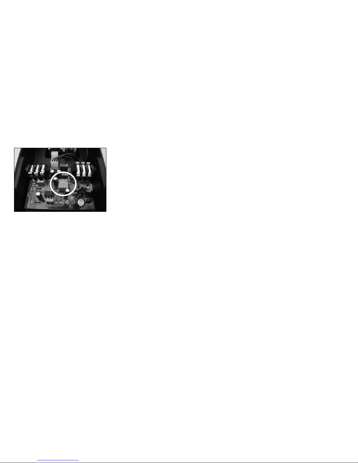
To locate the switch block, first unplug the external power
supply. Switch off the amplifier and remove all cables from
the pedal to the amp and instrument. Unscrew and remove the
four rubber feet and remove the base plate. The switch block
is located in the center of the circuit board.
SW1: Active/Passive switch. Default ON (passive). This
switch should be left on for most passive (un-powered)
guitar pick-ups. If using active, or very hot pickups, the
internal amplifier in the VM-PRO™ may be driven into
distortion. If this occurs, set SW1 to OFF for active
pickups.
SW2: Sparkle switch. Default OFF (flat). When turned on,
the high frequency response at low volumes is increased
adding some sparkle to the tone.
SW3: Impedance switch. Default ON (normal). This switch
should be left on for most applications. If connecting the
output of the VM-PRO™ directly to the input of a vintage
fuzz or similar sensitive input, this switch can be set OFF
to better match the impedance of the effect input.
Tun
The Mission VM-PRO™ features an isolated tuner out that
permits the connection of an electronic tuner without the
circuitry of that tuner impacting the signal to the amplifier
and thus affecting tone quality. The tuner signal is passed on
the ring of a TRS (stereo) jack. To use the tuner out, connect
a TRS insert adapter such as the Mission MCTRS-VMPRO to
OUT 1. The signal to your effects/amp is passed on the tip
and the signal to the tuner is passed on the ring. The MCTRSVMPRO is labelled AMP and TUNER for easy identification.
 Loading...