

Figure 1.
In odu ion
Congratulations on your purchase of the Mission
expression pedal. This product is designed to be
intuitive to setup and operate, and to provide
many years of trouble free service. However, we
recommend that you take a few moments to read
through this User Guide in order to get the best
possible experience with your new pedal.
f tur
This guide covers the following Mission model
numbers: EP-1, EP1-R, SP-1, SP1-R
The EP-1 and SP-1 are professional quality, all
metal expression pedals designed for use with TRS
expression pedal inputs on a wide variety of digital
amplifiers, effects, MIDI controllers and stomp
boxes. The -R models feature a polarity switch for
compatibility with a wide range of different devices.
The SP-1 models feature a second output connected
to a toe switch. The switch can be used with
compatible devices to support switchable functions
such as turning an effect on and off.
pow
The EP-1 and SP-1 pedals are passive devices and
require no internal battery or external power source
for expression control and switching. If your SP-1
is fitted with the optional LED indicator, an internal
9v battery is required to power the LED only. If the
battery is removed, the pedal will still function, only
the LED will be disabled.
ConnE ions
The EP-1 uses a single ¼” TRS phone plug outputs
marked OUT1 on the underside of the pedal.
Connect OUT1 to the expression pedal input on your
device using a ¼” TRS-TRS instrument cable such
as the Mission MCTRS3A cable. TRS stands for
Tip, Ring, Sleeve and is a three-conductor cable. It
is sometimes also called a stereo or balanced cable.
OUT1 requires the use of the correct cable with a
TRS connector at both ends. A mono TS cable such
as a regular guitar cable, and insert cables that have
both TS and TRS plugs, will not work in most cases.
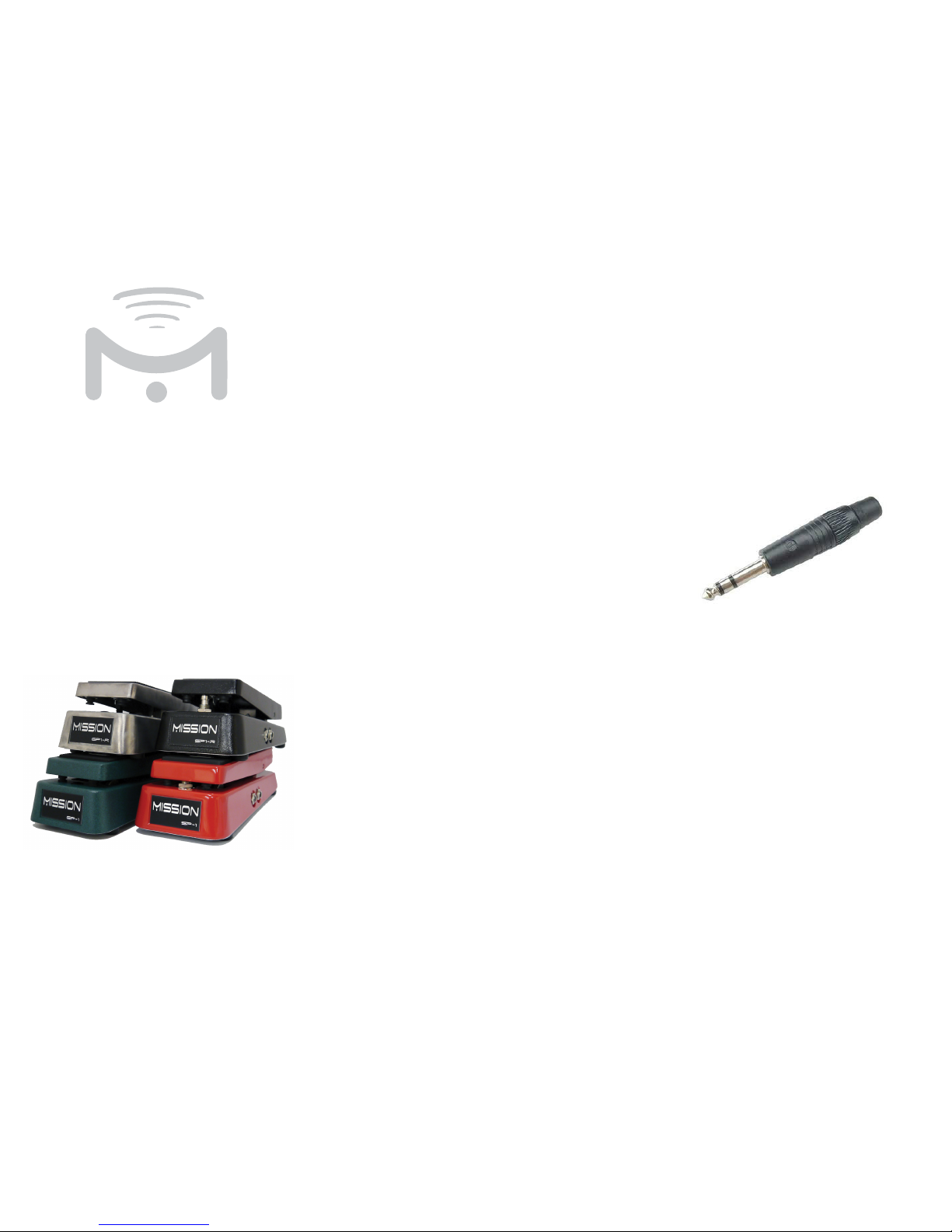
Figure 1. A TRS connector with the three conductors
separated by the black insulation bands. The pointed
front of the connector is the tip, the middle band is
the ring, and the large conductor at the rear nearest
the plug body is the sleeve.
The SP-1 features an additional output labeled
OUT2 that provides toe switching functions when
used with a compatible MIDI controller. Use of
the footswitch is optional. To use the footswitch,
connect OUT2 to a compatible input 2 on the
controller using a second TRS-TRS ¼” instrument
cable. The switch is operated by pushing down on
the front of the pedal with sufficient pressure to
actuate the switch.
no
The standard SP-1 is fitted with a TRS latching
foot switch. Different controller inputs may require
different switches. The SP-1 is interchangeable
between different types. User installable Switch
Kit’s are available from missionengineering.com
Expr sion
P A
EP-1
•
EP1-R
SP-1 • SP1-R
U r
Guide
MISSION
ENGINE ING

Mission Engin ring Inc.
www.missionengineering.com
info@mission-engineering.com
©
Mission Engineering Inc. 2013. All rights reserved. EP-1, EP1-R,
SP-1 and SP1-R are Trademarks of Mission Engineering Inc.
Trademarks, registered trademarks, product names, logos and other
materials are the property of their respective owners.
Sa ty
In ru ions
Read, Keep & Follow these instructions
Heed all warnings
Clean only with dry cloth
Do not use this apparatus near water
Do not expose the apparatus to dripping or
splashing and ensure that no objects filled with
liquids, shall be placed on the apparatus
WARNING: To reduce the risk of fire or electric
shock do not expose this apparatus to rain or
moisture
Unplug this apparatus during lightning storms or
when unused for long periods of time
Do not block any ventilation openings. Install in
accordance with the manufacturer’s instructions
Do not install near any heat sources such
as radiators, heat registers, stoves, or other
apparatus (including amplifiers) that produce
heat
Only use attachments/accessories specified by
the manufacturer
Prolonged listening at high volume levels may
cause irreparable hearing loss and/or damage.
Always be sure to practice “safe listening.”
Refer all servicing to qualified service personnel.
Service is required when the apparatus has been
damaged in any way, such as:
- power-supply cord or plug is damaged
- liquid has been spilled or objects have fallen
into the apparatus
- the unit has been exposed to rain or moisture.
- the unit is dropped or the enclosure is
damaged
- the unit does not operate normally or changes
in performance in a significant way
ecifi tions
Electrical Specifications
Potentiometer
Internal resistance - 10K Ohm
Taper - Linear
Polarity - Tip to wiper (ring to wiper capable with -R
option)
Function - Voltage Divider
Usage rating > 1M cycles
Switch
Type - Latching
Function - Toggles tip between ring and sleeve.
Dimensions
Base length at longest point - 9.9”
Base width at widest point - 4.0”
Height at highest point including feet - 3.25”
Pedal length - 8.7”
Pedal width at widest point - 3.0”
Pedal width at narrowest point - 2.3”
Weight - 3.5lbs
Po rity
Switch
Pedals fitted with the -R option feature a toggle
switch under the rocker in the center of the pedal.
The toggle can be used to switch OUT1 between
tip to wiper, or ring to wiper. The factory default is
tip to wiper (toggle position back). If you are using
the pedal with a device that requires reversed (ring
to wiper) configuration, switch the toggle to the
forward position.
Adju mEnts
The tension of the rocker can be adjusted using the
tension adjustment screw on the rear of the pedal
between the rocker and the base. Use the hex key
provided to tighten the adjustment screw until the
pedal remains in place. It maybe necessary to adjust
this screw every once in a while to compensate for
use and environmental conditions such as very hot or
cold weather, when the pedal has been stored for a
long period, or after shipping. Replacement hex keys
are available from Mission Engineering. The tension
adjuster is not included if the optional spring load has
been fitted.
The switch sensitivity on the SP-1 can be adjusted
by lowering or raising the switch in the chassis.
Use spacers and washers provided to lower the
switch making it harder to press. Remove spacers
and washers to raise the switch making it easier to
press. When replacing the switch, be careful not to
over tighten the lock nut and damage the switch.
 Loading...