

misia XM Maintance Manual

ELECTRIC WIRE ROPE HOIST
XM SERIES
MANUAL FOR INSTALLATION
OPERATION AND MAINTENANCE
M 26/09/18
www.misia.com


3
Manual for installation,
operation and maintenance of
the wire rope hoists XM Series
INDEX
1. PRELIMINARY INFORMATION Page 4
1.1 Compulsory warnings 4
1.2 Important information 4
1.3 Liability 5
1.3 Manual upgrading 5
2. DESCRIPTION OF THE HOIST/TROLLEY Page 6
2.1 Hoist configuration 6
2.2 Performance and technical features of the hoists with cylindrical/conical motors 8
2.3 Movement trolley features 10
2.4 Versions and standard use 11
2.5 Technical information 12
2.6 Choice of hoist based on FEM units 13
3. INSTALLATION INSTRUCTIONS Page 14
3.1 Installation preparations 14
3.2 Package 14
3.3 Transport and movement 15
3.4 Parts assembly 16
3.5 Mounting trolley Type 3 and 83 16
3.6 Mounting double rail trolley 18
3.7 Block mounting 18
3.8 Electrical equipment 19
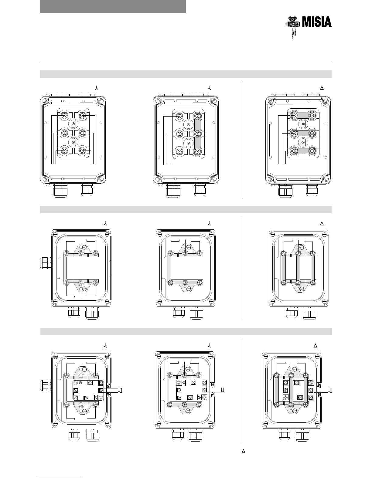
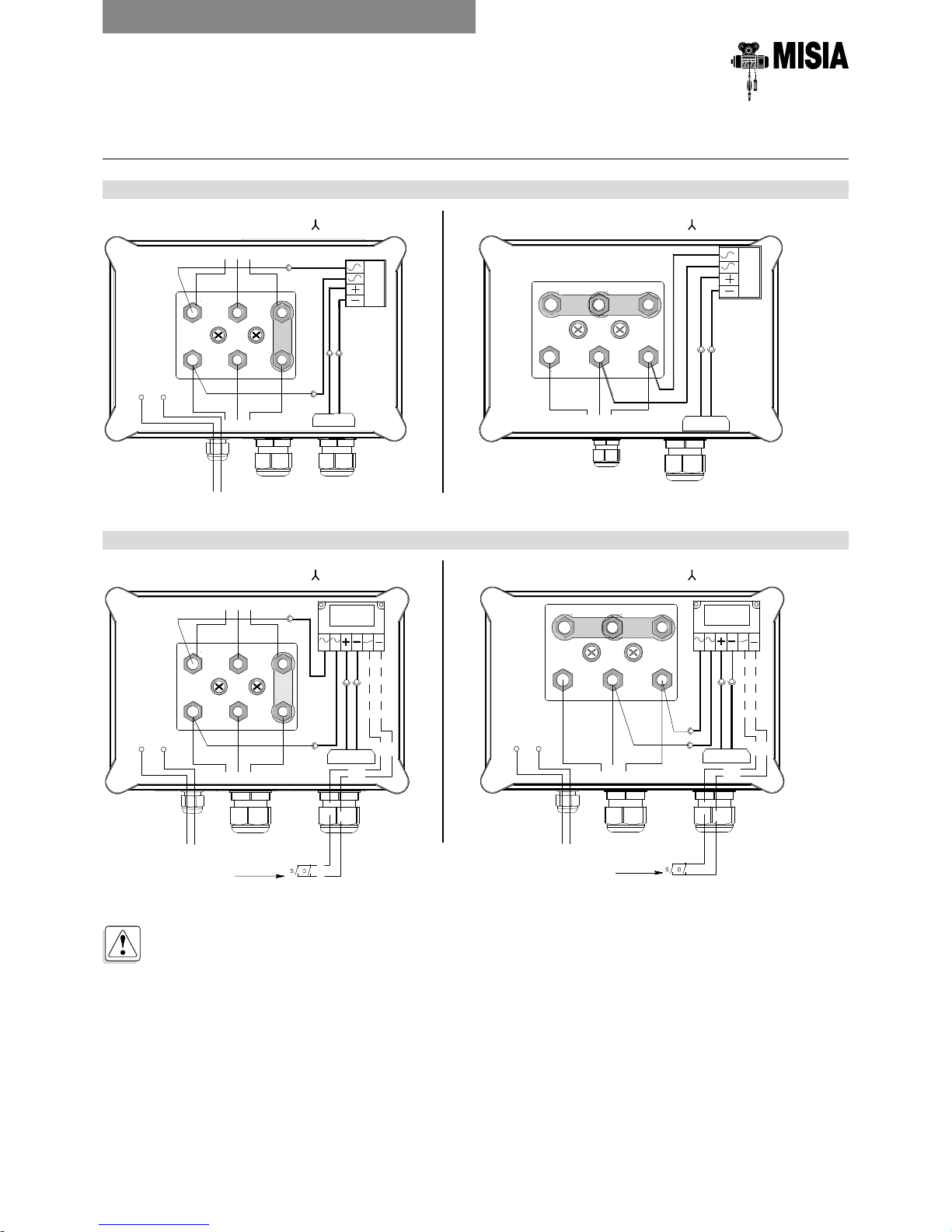
3.9 Electrical connections for hoists supplied without equipment 19
3.9.1 Wiring connections conical motors 1 or 2 speeds 20
3.9.2 Wiring connections cylindrical motors 1 or 2 speeds 21
3.9.3 Wiring connections cylindrical motors single speed suitable for vfd 22
3.9.4 Wiring connections cross travel motors 1 or 2 speeds model T and KT 24
3.9.5 End limit switch wiring connections 25
3.9.6 Electromechanical overload limiter DSET22 26
3.9.7 Conical motor wiring connections examples 29
3.9.8 Cylindrical motor wiring connection examples 33
3.9.9 Wiring connections c/t motors examples 37
3.9.10 Hoist and travel motors absorption 40
3.10 Start-up 41
3.11 Function tests and adjustments 42
3.12 Load testing 44
4. OPERATION AND MAINTENANCE INSTRUCTIONS Page 46
4.1 Hoist functions - “Intended purpose” 46
4.2 Before starting 46
4.3 What must always be done! 48
4.4 What must never be done! 50
4.5 Operation 52
4.6 Switching off at end of work 53
4.7 Maintenance 53
4.8 Lubrication 57
4.9 Replacements 58
4.10 Adjustments 65
4.11 Troubleshooting 68
4.12 Removal - New destination 69
4.13 Restoration after storage 69
4.14 Disposal/scrapping 69
5. MAINTENANCE REGISTER Page 70
5.1 Periodic maintenance reports 70
6. SPARE PARTS Page 70
4
Manual for installation,
operation and maintenance of
the wire rope hoists XM Series
Contents of the manual
This manual contains the description of the trolley/
hoist and its "intended purpose", the operation and
performance technical data and the installation,
operation and maintenance instructions for all
supported or suspended versions, with mono or
double rail trolley.
The manual also contains the following documents:
• CE conformity declaration or manufacturer
declaration;
• Test report of the machine, where applicable;
• Wiring diagrams, where applicable.
Recipients of this manual
This manual has been prepared for:
• The plant manager, workshop manager or site
manager;
• The installation technicians;
• The operator;
• The maintenance technicians.
The manual must be left in the safekeeping of a duly
authorised person, in an appropriate place where it is
always available in best conditions for reference.
In the event of loss or damage, ask for a copy directly
to MISIA PARANCHI srl indicating the code of this
manual.
How to use this manual
The instructions are accompanied by symbols
facilitating reading and specifying the various type of
information supplied.
1.1 COMPULSORY WARNINGS
Pay utmost attention to the instructions
accompanied by this symbol and strictly
observe the indications.
Important information:
Indicates useful information and hints
for handling, mounting and installation
operations.
Indicates to proceed with the operational
sequence.
Where necessary, references and numbers
corresponding to the illustrations appear throughout
the manual. In the illustrations any part of the trolley/
hoist described in the text is indicated with a number.
For example: Pos. 1 (fig. 1) means:
part or component 1 in figure 1.
1.2 IMPORTANT INFORMATION
Before starting any procedure, the relevant
section(s) of this instructions manual for the
activity to perform must be read.
The guarantee of problem-free and of full
correspondence of the performances with the
planned use strictly depends on the proper
application of all instructions contained in this
manual.
Reference legislative framework
The electric wire hoists XM Series and the relevant
movement trolleys comply with the Essential Safety
Requirements pursuant to Annex I of Machinery
Directive 2006/42/EC and are therefore provided with
a CE Declaration of Conformity pursuant toAnnex
IIA and the CE Mark pursuant toAnnex III of the same
Directive.
Furthermore, the electric wire hoists XM Series and the
relevant electric trolleys comply with the Low Voltage
Directive 2006/95/EC and the Electromagnetic
Compatibility Directive 2004/108/EC.
1. PRELIMINARY INFORMATION
Reproduction
of the Declaration
of Conformity
FACSIMILE
ELECTRIC WIRE ROPE HOIST
XM SERIES
5
1 . PRELIMINARY INFORMATION
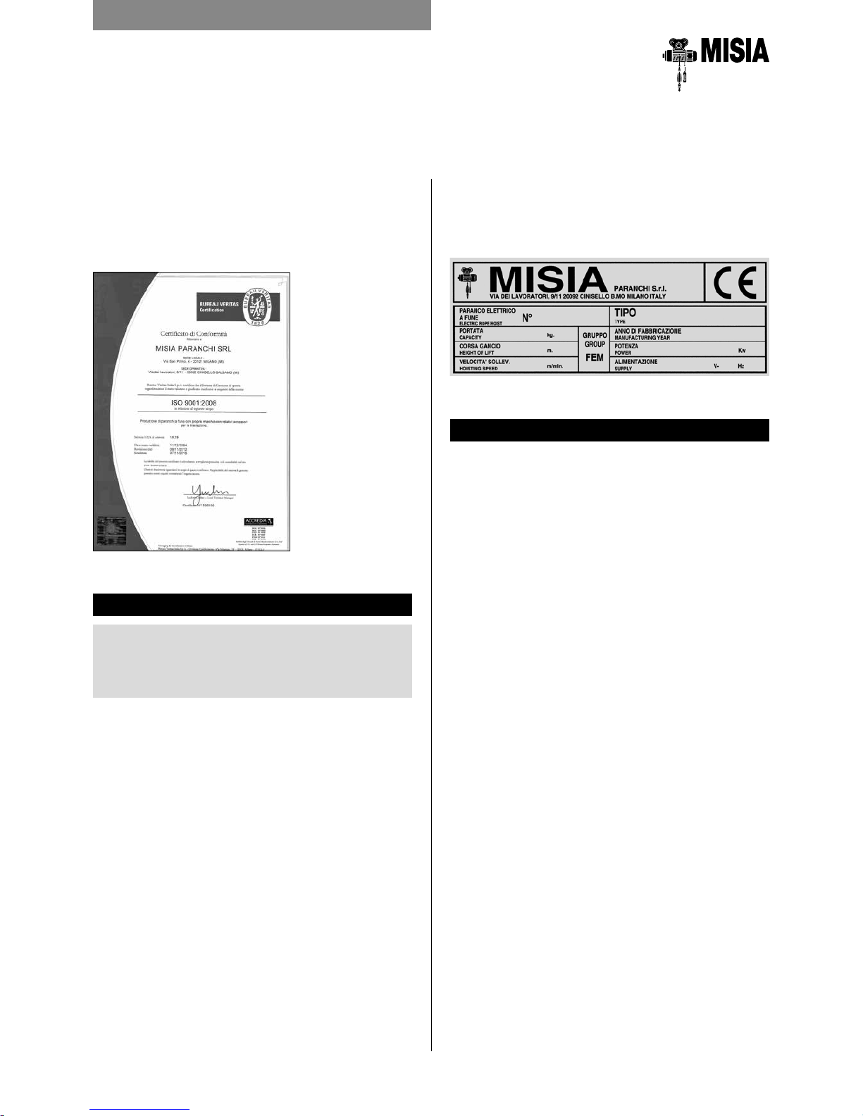
MISIA manufactures and distributes electric wire hoists
under the company quality system in compliance with
the standards: UNI EN ISO 9001, with the following
international certificates released by the BV test
company: ACCREDIA - Italy.
Plate types:
• Identification plate for the hoist/trolley
• Hoist and travel motors plate
• Blocks plate
1.4 MANUAL UPGRADING
This manual illustrates the state-of-the-art machine at
the time it was introduced on the market. This manual
is part of the machine and complies with all laws,
directives and regulations in force at this time, therefore,
this manual cannot be considered inadequate solely
because it was subsequently updated due to new
information becoming available.
Any changes, adaptations, etc. to the machine sold in
the future do not oblige the manufacturer to intervene
on the previously supplied equipment, nor should the
manual or the equipment be considered lacking or
inadequate.
Any integrations to the manual sent by the
manufacturer to users must be saved with the
relevant manual.
FACSIMILE
1.3 LIABILITY
The instructions in this manual do not substitute,
but only summarise the obligations stated by
the actual safety and injury prevention laws and
regulations.
With reference to the content of this instructions
manual, MISIA declines any liability in the following
cases:
• Use non-compliant with national safety and injury
prevention laws and regulations:
• Defective layout of the structures on which the hoist
is intended to operate;
• Failure to read or comply with the instructions in this
manual;
• Faults in the main power supply;
• Unauthorised changes to the hoist;
• Use by untrained staff.
Readability and preservation of plates
Plates must always be maintained in a readable
condition for all their details and periodically cleaned. If
only some of the information on the plate deteriorates
or is no longer legible, we recommend ordering a new
plate from the manufacturer quoting the data in this
manual or on the original plate, especially the serial
number and proceed to replace it.
6
2. DESCRIPTION OF THE HOIST/TROLLEY
2.1 HOIST CONFIGURATION
The electric hoists were designed and tested according
to the FEM calculation rules for lifting equipment.
According to the intended operation, the electric hoists
can be:
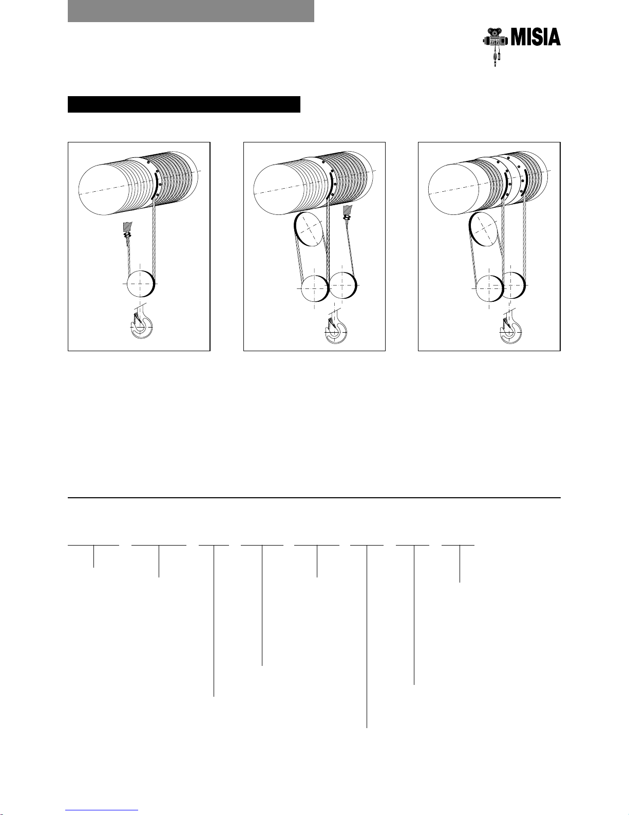
Lifting mechanism
The lifting mechanism is composed of the following
assemblies:
1. planetary gear;
2. hoist body;
3. rope drum;
4. coupling;
5. rope guide;
6. block;
7. self-braking electric motor.
a) standard feet
mounted;
d) with double
rail trolley and
supported or
suspended
hoist.
c) with low headroom, monorail trolley.
This reduces the distance between the suspension
point of the load on the hook and the travel surface;
b) with standard,
monorail trolley.
Hoists 308÷525
Hoists 740÷1125
Manual for installation,
operation and maintenance of
the wire rope hoists XM Series
Type 5-5C1
Type 53-53C1
Type 3
Type 83

7
ELECTRIC WIRE ROPE HOIST
XM SERIES
2. DESCRIPTION OF THE HOIST/TROLLEY
Hoisting motor, self-braking and conical
Three-phase asynchronous 1 or 2 speed electric motor
with cone rotor and integrated cone brake driven by a
coil spring. The brake is released due to axial sliding of
the rotor after power is switched on.
Hoisting and travel motor, self-braking
and cylindrical
Three-phase asynchronous, 1 or 2 speed electric
motor with cylindrical rotor, with a DC brake. The
single polarity motor can be inverter driven to obtain
the slow speed required as well as the acceleration or
deceleration ramps.
Coupling
The torque of the motor is transmitted to the shaft of
the gearbox by a toothed coupling connected to the
gearbox shaft.
Planetary gear
The two or three stage planetary gear reduces the
rotation speed of the electric motor to the number of
rotations necessary for the drum.
All gears on the gearbox are in heat treated high quality
steel.
Drum
The drum is driven centrally by the hollow output
shaft on the gearbox. The shaft on the gearbox and
the guide plate on the second stage are supported
on roller bearings on which the drum is installed. For
hoists Type 740-750-950-963-980-1100-1125 the
gearbox is located inside the drum.
The profile of the rope grooves on the drum are
manufactured in compliance with DIN standards.
Rope guide
The rope guide is essentially composed of two parts: a
guide ring and a pressure ring that properly guide the
rope on the drum grooves. The guide ring maintains
the rope in position during uncoiling, preventing it
coming off the groove and, when the load swings, is
guided by a fixed bar and runs on a roller bearing.
Hoist body
The supporting framework is composed of a compact
welded structure made of two steel flanges joined by
profiled plates.
Block with hook
The structure of the block with the 2 or 4 rope falls
allows distribution of the tensile force generated from
the ropes load. The side covers of the block covering
the pulleys are strong and shock resistant.
Load limiter
All the hoists in the "XM" Series with 2 and 4 rope falls
are systematically equipped with a load limiter.
The load limiters intervene on the auxiliary circuit
by signalling the maximum nominal load and, in the
event of overcharging, stops the ascent operation and
movement.
A Electronic device with dynamometric pin with
relevant pre-calibrated board, with two intervention
thresholds;
B Electromechanical device with pre-calibrated
spring, with two intervention thresholds.
Electrical system
The hoist trolley, where required, can be provided with it
own electrical system which includes: electromagnetic
switches to control all hoist movement, as well the
protection fuses against short circuit. The control
circuits are low voltage (48/110 volts). A terminal box
with numbered terminals ensures simplicity and safety
in the wiring for all external functions.

8
ELECTRIC WIRE ROPE HOIST
XM SERIES
2. DESCRIPTION OF THE HOIST/TROLLEY
*
Motors used with inverter
2.2 PERFORMANCE AND TECHNICAL FEATURES
Cylindrical motors
Motor features
Normal voltages:
• 400 V - 230 V at 50 Hz three phase
• Motors with special voltage and frequency are made
available (to be defined upon order or offer).
• Only for tapered single polarity motors it is always
possible the / voltage switching (400V star / 230V
triangle). For all other motors the voltage must be
specified.
• The motor consumption values are indicated in table
2 on page 40.
The STD motor are manufactured for use
relating to group FEM 2m, precisely: 240
no. of start I.R. 40% fast and 15% slow, non
cumulative.
Special voltages:
On request, voltages other than those indicated can
be supplied
NOTE - Auxiliary speeds can only be used for a
limited time, based on the intermittent duty rates
(for example: spotting) and not as the normal
operating speed.
Capacity Group Hoist Rope falls Hook stroke Lifting speed/Motor power
kg FEM XM No.
HmHmHmH
m
N V NA VA
m/min
kW
*
m/min
kW
*
m/min kW m/min kW
1000 3m 308 2/1 10 14 20 26 8 2,5 12 2,5 8/2,6 2,5/0,83 12/4 2,5/0,83
1250 3m 308 2/1 10 14 20 26 8 2,5 12 4 8/2,6 2,5/0,83 12/4 4/1,3
1600 2m 308 2/1 10 14 20 26 8 2,5 12 4 8/2,6 2,5/0,83 12/4 4/1,3
2000
3m 308 4/1 / 7 10 13 4 2,5 6 2,5 4/1,3 2,5/0,83 6/2 2,5/0,83
3m 312 2/1 10 14 20 26 8 4 12 5 8/2,6 4/1,3 12/4 5/1,6
2500
3m 308 4/1 / 7 10 13 4 2,5 6 4 4/1,3 2,5/0,83 6/2 4/1,3
2m 312 2/1 10 14 20 26 8 4 12 5,8 8/2,6 4/1,3 12/4 5,8/1,9
3200
2m 308 4/1 / 7 10 13 4 2,5 6 4 4/1,3 2,5/0,83 6/2 4/1,3
2m 316 2/1 10 14 20 26 8 5 12 7 8/2,6 5/1,6 12/4 7/2,3
4000
3m 312 4/1 / 7 10 13 4 4 6 5 4/1,3 4/1,3 6/2 5/1,6
3m 525 2/1 10 14 20 26 8 8 12 12 8/2,6 8/2,6 12/4 12/4
5000
2m 312 4/1 / 7 10 13 4 4 6 5,8 4/1,3 4/1,3 6/2 5,8/1,9
3m 316 4/1 / 7 10 13 4 4 6 5,8 4/1,3 4/1,3 6/2 5,8/1,9
2m 525 2/1 10 14 20 26 8 8 12 12 8/2,6 8/2,6 12/4 12/4
6300
2m 316 4/1 / 7 10 13 4 5 6 7 4/1,3 5/1,6 6/2 7/2,3
2m 740 2/1 13 18 25 32 8 12 / / 8/2,6 12/4 / /
8000
3m 525 4/1 / 7 10 13 4 8 6 12 4/1,3 8/2,6 6/2 12/4
2m 740 2/1 13 18 25 32 8 12 / / 8/2,6 12/4 / /
3m 750 2/1 13 18 25 32 / / 8 12 / / 8/2,6 12/4
10000
2m 525 4/1 / 7 10 13 4 8 6 12 4/1,3 8/2,6 6/2 12/4
2m 750 2/1 13 18 25 32 / / 8 15 / / 8/2,6 15/5
3m 963 2/1 20 32 48 / / / 8 16 8/2,6 16/5,3 9/3 18/6
12500
3m 740 4/1 6,5 9 12,5 16 4 12 / / 4/1,3 12/4 / /
2m 963 2/1 20 32 48 / / / 8 20
8/2,6 20/6,5 / /
16000
2m 740 4/1 6,5 9 12,5 16 4 12 / / 4/1,3 12/4 / /
3m 750 4/1 6,5 9 12,5 16 / / 4 12 / / 4/1,3 12/4
1Am 980 2/1 20 32 48 / 5 16 7,5 24 / / / /
20000
2m 750 4/1 6,5 9 12,5 16 / / 4 15 / / 4/1,3 15/5
3m 963 4/1 10 16 24 / 5 20 6 24 5/1,6 20/6,5 / /
2m 1100 2/1 20 24 30 44 4 16 5 20 4/1,3 16/5,3 5/1,6 20/6,5
25000
2m 963 4/1 10 16 24 / / / 4 20 4/1,3 20/6,5 / /
1Am 1125 2/1 20 24 30 44 4 20 5 24 4/1,3 20/6,5 / /
32000 1Am 980 4/1 10 16 24 / / / 4 24 / / / /
40000 2m 1100 4/1 10 12 15 22 2 16 2,5 20 2/0,6 16/5,3 2,5/0,8 20/6,5
50000 1Am 1125 4/1 10 12 15 22 2 20 2,5 24 2/0,6 20/6,5 / /

9
ELECTRIC WIRE ROPE HOIST
XM SERIES
2. DESCRIPTION OF THE HOIST/TROLLEY
Conical motors
Motor features
Normal voltages:
• 400 V - 230 V at 50 Hz three phase
• Only for single speed motors it is always possible to
change tension Y “star” to “delta” connection.
• For bipolar motors, specify the exact mains voltage
• The motor consumption values are indicated in table
2A on page 40
The STD motor are manufactured for use
relating to group FEM 2m, precisely: 240
no. of start I.R. 40% fast and 15% slow, non
cumulative.
Special voltages:
On request, voltages other than those indicated can
be supplied
NOTE - Auxiliary speeds can only be used for a
limited time, based on the intermittent duty rates
(for example: spotting) and not as the normal
operating speed.
Capacity Group Hoist Rope falls Hook stroke Lifting speed/Motor power
kg FEM XM No.
HmHmHmH
m
N V NA VA
m/min kW m/min kW m/min kW m/min kW
1000 3m 308 2/1 10 14 20 26 8 2,5 12 2,5 8/2,6 3/1 12/4 3/1
1250 3m 308 2/1 10 14 20 26 8 2,5 12 4,5 8/2,6 3/1 12/4 3/1
1600 2m 308 2/1 10 14 20 26 8 2,5 12 4,5 8/2,6 3/1 12/4 4,5/1,5
2000
3m 308 4/1 / 7 10 13 4 2,5 6 2,5 4/1,3 3/1 6/2 3/1
3m 312 2/1 10 14 20 26 8 4,5 12 4,5 8/2,6 3/1 12/4 4,5/1,5
2500
3m 308 4/1 / 7 10 13 4 2,5 6 4,5 4/1,3 3/1 6/2 4,5/1,5
2m 312 2/1 10 14 20 26 8 4,5 12 5,5 8/2,6 4,5/1,5 12/2 6/1
3200
2m 308 4/1 / 7 10 13 4 2,5 6 4,5 4/1,3 3/1 6/2 4,5/1,5
2m 316 2/1 10 14 20 26 8 4,5 / / 8/2,6 4,5/1,5 / /
4000
3m 312 4/1 / 7 10 13 4 4,5 6 4,5 4/1,3 3/1 6/2 4,5/1,5
3m 525 2/1 10 14 20 26 8 7,5 12 12 8/1,3 8/1,3 12/2 12,5/1,7
5000
2m 312 4/1 / 7 10 13 4 4,5 6 5,5 4/1,3 4,5/1,5 6/1 6/1
3m 316 4/1 / 7 10 13 4 4,5 6 5,5 4/1,3 4,5/1,5 6/1 6/1
2m 525 2/1 10 14 20 26 8 7,5 6 12 8/1,3 8/1,3 12/2 12,5/1,7
6300
2m 316 4/1 / 7 10 13 4 4,5 / / 4/1,3 4,5/1,5 / /
2m 740 2/1 13 18 25 32 / / / / 8/1,3 13/2,2 / /
8000
3m 525 4/1 / 7 10 13 4 7,5 6 12 4/0,7 8/1,3 6/1 12,5/1,7
2m 740 2/1 13 18 25 32 / / / / 8/1,3 13/2,2 / /
3m 750 2/1 13 18 25 32 5 12,5 / / 5/1,2 13/3 8/1,3 13/2,2
10000
2m 525 4/1 / 7 10 13 4 7,5 6 12 4/0,7 8/1,3 6/1 12,5/1,7
2m 750 2/1 13 18 25 32 5 12,5 / / 5/1,2 13/3 8/1,3 15/2,5
3m 963 2/1 20 32 48 / 6 12,5 / / 6/1,5 13/3 / /
12500
3m 740 4/1 6,5 9 12,5 16 / / / / 4/1 13/3 / /
3m 963 2/1 20 32 48 / 5 12,5 / / 5/1,2 13/3
/ /
16000
2m 740 4/1 6,5 9 12,5 16 / / / / 4/0,7 13/2,2 / /
3m 750 4/1 6,5 9 12,5 16 2,5 12,5 / / 2,5/0,6 13/3 4/0,7 13/2,2
1Am 980 2/1 20 32 48 / / / / / 5/1,2 16/4 / /
20000
2m 750 4/1 6,5 9 12,5 16 2,5 12,5 / / 2,5/0,6 13/3 4/0,7 15/2,5
3m 963 4/1 10 16 24 / 3 12,5 / / 3/0,75 13/3 / /
2m 1100 2/1 20 24 30 44 3 12,5 / / 3/0,75 13/3 5/0,8 20/3,3
25000
2m 963 4/1 10 16 24 / 2,5 12,5 / / 2,5/0,6 13/3 4/0,7 20/3,3
1Am 1125 2/1 20 24 30 44 / / / / 3/0,75 16/4 4/0,7 20/3,3
32000 1Am 980 4/1 10 16 24 / / / / / 2,5/0,6 16/4 / /
40000 2m 1100 4/1 10 12 15 22 / / / / 1,5/0,37 13/3 2,5/0,4 20/3,3
50000 1Am 1125 4/1 10 12 15 22 / / / / 1,5/0,37 16/4 2/0,35 20/3,3
10
ELECTRIC WIRE ROPE HOIST
XM SERIES
2. DESCRIPTION OF THE HOIST/TROLLEY
Capacity Group Hoist
Rope
falls
Trolley speed and motor power
Monorail Double rail
Type: 3-43 Type: 83 Type: 53-53C1
kg FEM XM No. m/min
kW
*
m/min kW m/min
kW
*
m/min kW m/min
kW
*
m/min kW m/min kW m/min kW
1000 3m 308 2/1
18
0,37
18/6
0,37/0,12
20 2x0,25 20/5 2x0,24/0,06
16
0,37
16/5,3
0,37/0,12
20
0,37
20/6,5
0,37/0,12
1250 3m 308 2/1
1600 2m 308 2/1
2000
3m 308 4/1
3m 312 2/1
2500
3m 308 4/1
2m 312 2/1
3200
2m 308 4/1
2m 316 2/1
4000
3m 312 4/1
3m 525 2/1
5000
2m 312 4/1
3m 316 4/1
2m 525 2/1
6300
2m 316 4/1
0,55 0,55/0,18
2m 740 2/1 ⁄ ⁄ ⁄ ⁄
8000
3m 525 4/1 20 2x0,30 20/5 2x0,30/0,07
0,55 0,55 0,55/0,18 0,55/0,18
2m 740 2/1
⁄ ⁄ ⁄ ⁄
3m 750 2/1
10000
2m 525 4/1 20 2x0,30 20/5 2x0,30/0,07
2m 750 2/1
2x0,37 2x0,37/0,12
⁄ ⁄ ⁄ ⁄
3m 963 2/1
0,75 0,75/0,25 1,1 1,1/0,37
12500
3m 740 4/1
1Am 963 2/1
16000
2m 740 4/1
2x0,55 2x0,55/0,18
2m 750 4/1
3m 963 4/1
20 2x0,75 20/6,5 2x0,75/0,25
1Am 980 2/1
20000
2m 750 4/1
1,1 1,1/0,37 1,5 1,5/0,55
3m 963 4/1
2m 1100 2/1
25000
2m 963 4/1
1Am 1125 2/1 ⁄ ⁄ ⁄ ⁄
32000 1Am 980 4/1 20 2x1,1 20/6,5 2x1,1/0,37 2x1,1 2x1,1/0,37 2x1,1 2x1,1/0,37
40000 2m 1100 4/1
⁄ ⁄ ⁄ ⁄ 2x1,5 2x1,5/0,55 2x1,5 2x1,5/0,55
50000 1Am 1125 4/1
*
Motors used with inverter
Motor features
• The motor consumption values are indicated in table
3-4-5 on page 40
The STD motor are manufactured for use
relating to group FEM 2m, precisely: 240
no. of start I.R. 40% fast and 15% slow, non
cumulative.
NOTE - Auxiliary speeds can only be used for a
limited time, based on the intermittent duty rates
(for example: spotting) and not as the normal
operating speed.
2.3 MOVEMENT TROLLEY FEATURES
Trolleys
11
ELECTRIC WIRE ROPE HOIST
XM SERIES
2. DESCRIPTION OF THE HOIST/TROLLEY
XM 312 A a/5S4 H7N
Series
Hoist
size
2
nd
lifting speed
(where requested)
2
nd
travel speed
(where requested)
Type:
5 supported
5C1 suspended
3 standard monorail trolley
83 low headroom monorail trolley
53 double rail trolley with rested hoist
53C1 double rail trolley with suspended hoist
Version:
S2 - 2 rope falls 2/1
S4 - 4 rope falls 4/1
D2 - 4 rope falls 4/2
Hook stroke
N 1 speed normal lifting
V 1 speed fast lifting
S2
2/1
S4
4/1
D2
4/2
S4
4/1
D2
4/2
D2
4/2
S2 - 2 ROPE FALLS (2/1) S2 - 4 ROPE FALLS (4/1) D2 - 4 ROPE FALLS (4/2)
CENTRAL FALL
2.4 STANDARD VERSIONS AND USE
Rope fall arrangement
Standard use
Example of hoist code composition
12
ELECTRIC WIRE ROPE HOIST
XM SERIES
2.5 TECHNICAL INFORMATION
Reference legislative framework
The design and construction of the electric rope hoists
"XM" Series and the relevant movement trolleys took
into consideration the following main standards and
technical regulation:
• EN ISO 12100:2010 Main fundamental
general design concepts.
• EN ISO 13849-1:2008 Parts of the command system
relating to safety.
• EN 12385-4:2008 Steel ropes - Safety
Part 4 - Stranded ropes for general lifting use.
• EN 13135-1:2010 Lifting devices
Part 1 - Electrical and technical equipment.
• EN 13135-2:2010 Lifting devices
Part 2 - Non-electrical and technical equipment.
• EN 12077-2:2008 Limiting and indication devices.
• EN 13001-1:2009 Lifting equipment -
General criteria for the project
Part 1 - Principles and main requirements.
• EN 13001-2:201.1 Lifting equipment -
General criteria for the project
Part 2 - Load actions.
• EN 13001-3-1:2012 Lifting equipment -
General criteria for the project
Part 3-1 - Limit statuses.
• EN 14492-2:2009 Lifting equipment -
Part 2 - Motorised hoists.
• EN 60204-32:2008 Safety of electrical equipment
on lifting machinery.
• EN 60529:1997 Level of casing protection (lP Codes).
• ISO 4301-1:1988 Lifting equipment -
Classification - Part 1 - General information.
• ISO 4308-1:2003 Lifting equipment -
Rope selection - Part 1 - General information.
• DIN 15400 Selection of lifting hooks -
Mechanical and support properties.
• DIN 15401 Selection of lifting single hooks.
• FEM 1.001/98 Calculation of lifting equipment.
• FEM 9.511/86 Classification of mechanisms.
• FEM 9.661/86 Selection of drums, ropes and pulleys.
• FEM 9.683/95 Choice of lifting
and travel motors.
• FEM 9.755/93 Safe work periods.
• FEM 9.761/93 Load limiters.
• FEM 9.941/95 Command symbols.
Operating conditions
The MISIA standard hoists are manufactured to work
in environmental conditions characterised by:
• min. temperature. -10°C ÷ max +40°C
• relative humidity < 80%
• altitude max 1000 a.s.l.
When operation of the hoist is planned in other
environmental conditions to those standard conditions,
special versions are available on request.
Noise
The sound pressure level emitted when all the parts
of the hoist are working is clearly under 85 dB(A)
measured 1 m distance and 1.60 metres off the ground.
Electrical power supply
Serial MISIA hoists are designed for three-phase AC
power 400Volt / 50Hz ± 10%.
Motors with special voltage and frequency are made
available (to be defined upon order or offer).
Only for tapered single polarity motors it is always
possible the / voltage switching (400V star / 230V
triangle). For all other motors the voltage must be specified.
The design of the power supply line must be adequate
for the power and absorption of the motor relevant
to configuration of the machine planned in the sales
quote (see table 6 on page 41).
Motors for special voltages and frequencies other than
standard supplies are available on request.
Hoists for outdoor use, guards and insulation other
than standard ones are available on request.
Conical motors Table 1
Function
Guard
Class of
insulation
Motor Brake
Lifting IP54 IP23 F
Movement IP54 IP23 F
Cylindrical motors Table 2
Function
Guard
Class of
insulation
Motor Brake
Lifting IP55 IP55 F
Movement IP55 IP55 F
Electrical systems Table 3
Part Guard
Max insulation
voltage
Electric box IP55 1,500 V
Cables CE 120/22 450/750 V
Connectors IP55 600 V
Keypad IP55 500 V
Limit switch IP54 500 V
2. DESCRIPTION OF THE HOIST/TROLLEY
Standard guards and insulation
MISIA hoists are designed for use in an environment
protected from atmospheric agents. Electrical parts are
supplied with the guards and insulation as indicated in
Tables 1, 2 and 3.
13
ELECTRIC WIRE ROPE HOIST
XM SERIES
2. DESCRIPTION OF THE HOIST/TROLLEY
For hoists that rarely lift
the maximum load and
mainly reduced loads.
For hoists lifting
approximately the
same ratio maximum,
medium and reduced
loads.
For hoists that
frequently lift the
maximum load and
normally medium loads.
For hoists that regularly
lift loads near the
maximum value.
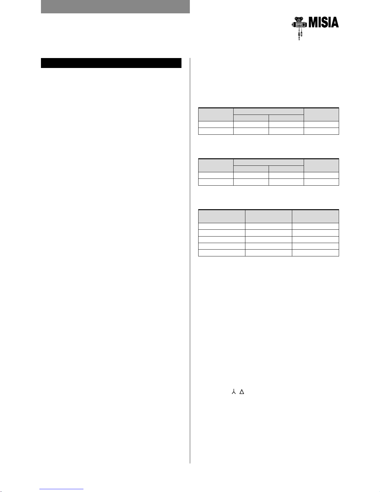
Duty class Running time "T"
L1 - Light 6300 12500
L2 - Medium 3200 6300
L3 - Heavy 1600 3200
L4 - Very heavy 800 1600
FEM Group 1A m 2 m
% tempo di funzionamento
% carico
0
100
100
% tempo di funzionamento
% carico
0
100
100
% tempo di funzionamento
% carico
0
100
100
% tempo di funzionamento
% carico
0
100
100
% tempo di funzionamento
% carico
0
100
100
% tempo di funzionamento
% carico
0
100
100
% tempo di funzionamento
% carico
0
100
100
% tempo di funzionamento
% carico
0
100
100
% tempo di funzionamento
% carico
0
100
100
% tempo di funzionamento
% carico
0
100
100
L1 Light L2 Medium
L3 Heavy L4 Very Heavy
2.6 CHOICE OF HOIST BASED ON FEM GROUPS
The duty class of hoist use is determined by two
parameters:
a) running time;
b) duty class.
Temporary service
As foreseen in the FEM 9.681 e 9.682 rules, electric
self-braking motors for movement and lifting are
designed and manufactured for use in intermittent
service in relation to the selected duty class. However,
for example for long movement or high hook strokes,
these intermittent duty rates may not be respected. In
these cases, the hoist may be operated in temporary
service with the possibility of establishing the running
time while taking into consideration the permissible
temperature limits of the motors. In these cases, make
sure the motors are not started more than ten times
and for the corresponding maximum running time, in
compliance with the aforementioned FEM standards,
of the chosen duty class (see table).
Comparison between duty classes
FEM section IX (standard hoists) E
FEM section I and ISO (special hoists)
FEM 9.511 FEM Sect. I-ISO
1C m M2
1B m M3
1A m M4
2 m M5
3 m M6
4 m M7
Temporary service (high hook strokes and long movements)
Group
Continuous
running
time min.
Max. no. of consecutive
start-ups during
the running time
FEM ISO
1B m M3
15 10
1A m M4
2 m M5
30 10
3 m M6
14
Inspect the working area where the hoist will
be operating:
• Check that there are no obstacles in the way of the
hook during lifting.
• For a hoist with trolley, make sure that travel and
lifting movements are free from obstacles and are
not dangerous to people, things and the workplace.
• Make sure that no permanent working activities are
performed under the operating area of the trolley.
Provide suitable test weights for dynamic and
static load tests, with suitable sling and lifting
equipment, as follows:
3. INSTALLATION INSTRUCTIONS
3.1 PREPARATION FOR INSTALLATION
Before starting installation, make sure the
technical data of the hoist and the parts to be
prepared by the user comply with the content
of the order confirmation, in order to ensure a
proper installation, especially:
Verify the suitability of the rail or the fixed
support to hold the hoist, as well as the feeding
line.
3.2 PACKAGE
Check in the packaging-list, or the delivery
note, the list of documents supplied with the
equipment (including the instruction, operation
and maintenance manual, the various certificates
and the conformity declaration). The hoist can
be delivered on: pallets, crate, closed case,
according to the requirements of the customer
when making the order. For "closed cases"
respect the handling instructions as well as the
indications and symbols marked thereon.
Before handling the packaging, take note of the
weight of the load unit signed on the package
and use proper tools.
If the hoist should not be installed immediately,
note the following points:
The standard packaging is not rainproof" and
is intended for transport by land, and not by
sea, inside covered rooms, without humidity.
The packed and suitable preserved equipment
can be stored indoors for a period of about 5
years, at a temperature between -20° and +70°C
and 80% humidity. Different environmental
conditions require a special package.
Identify the hold points, if any, marked on each
package unit with the corresponding symbol.
Before handling the load unit, visually check
the package, and consequently the goods, for
breaks or damages.
DYNAMIC TEST
mass=
rated capacity x 1.1
STATIC TEST
mass=
• rated capacity x 1.25
besides the rated capacity of 1000 kg.
• rated capacity x 1.5
up to rated capacity of 1000 kg.
• the static test must be carried out
without starting the motor, but only
by applying the load to verify the
hold of the brake (see page 45).
Check the suitability of the power supply line
and the current / voltage values accordingly to
the content of the order confirmation.
Verify that this documentation corresponds to the
hoist to be installed.
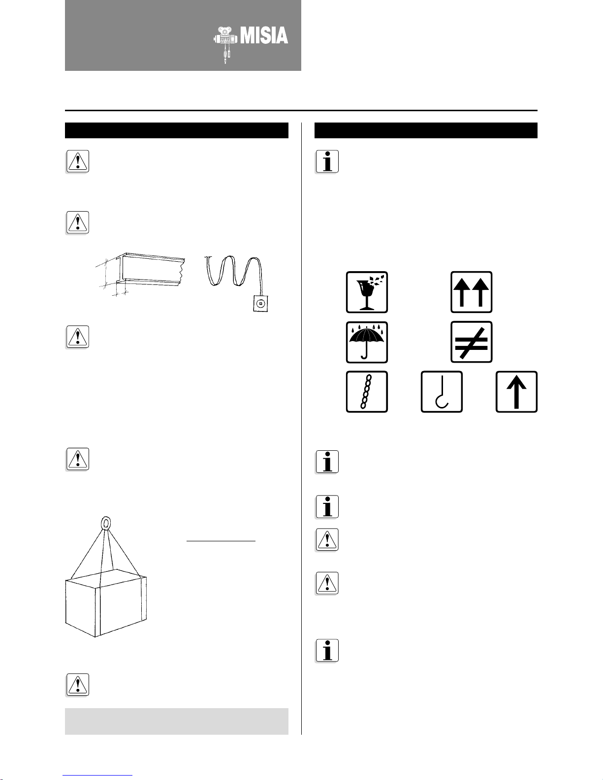
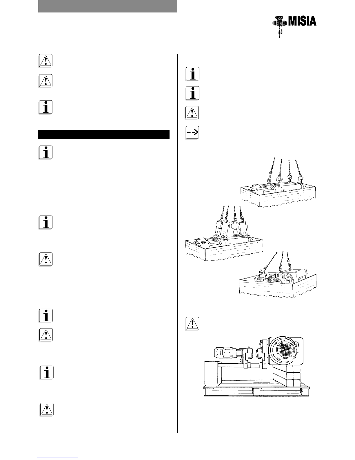
Instructions on lifting means and holding points
Handle
with care
Do not
overturn
Protect
from rain
Do not
stack
Manual for installation,
operation and maintenance of
the wire rope hoists XM Series
15
ELECTRIC WIRE ROPE HOIST
XM SERIES
3. INSTALLATION INSTRUCTIONS
3.3.2 PACKAGE REMOVAL
To extract the hoist from the package no
special slings are required.
Use adequate slings for the mass of the hoist
to be lifted.
After package removal, visually check the hoist
for integrity before starting installation.
To extract the hoist, hook the slings to the
points provided, as shown in the illustrations.
Using the ring bolts ØM shown in table A on
page 16.
3.3 TRANSPORT AND MOVEMENT
In order to ensure careful and proper handling
of the equipment, we recommend you entrust
qualified carriers with the transport. No other
goods can be laid on the equipment or its
package. During transport the goods must
be properly covered to provide waterproof
protection against rain.
In case of shipping, the package units must be
kept in the hold protected against sprinkling
water or humid winds.
Handle with suitable means, lifting the
equipment without dragging it.
3.3.1 STORAGE
The goods, whether designed for indoor or
outdoor installation, can be stored up to a
maximum period of 5 years in an environment
with the following characteristics:
• protected against atmospheric agents;
• humidity not higher than 80%;
• minimum temperature -20°C;
• maximum temperature +70°C.
For storage periods over 5 years, ask the
manufacturer for special protection procedures.
Should these values change during storage,
preliminary checks must be performed before
putting the hoist into service.
(refer to section 4.13 "Restoration after
storage" on page 69).
If in storage the temperature rises above or
falls below the given values and the humidity
exceeds 80%, provide protection for the
packages with barrier bags and hygroscopic
salts.
In case of storage outdoors:
• provide for supports to keep all packages
without pallets clear of the floor;
• protect all packages with barrier bags and
hygroscopic salts.
NEVER USE SLING CHAINS TO LIFT OR
MOVE THE PACKAGE UNIT
LIFT THE PACKAGED HOIST WITH THE
FORKS OF A LIFT TRUCK OR BY MEANS
OF A TRANSPALLET
Dispose of the package according to legal
specifications.
Once the hoist is removed from the packaging,
put it on a pallet and ensure its stability.

16
ELECTRIC WIRE ROPE HOIST
XM SERIES
ØM
e
h
(coupling thickness)
For any changes please contact the Technical
Department of MISIA.
3.4 PARTS SSEMBLY
Verify the technical data of the hoist comply
with the foreseen kind of operation, especially
the hook travel is not shorter than required and
that the operation capacity is equal or greater
than the loads to be lifted.
To assemble hoists Type 5C1 (suspended type)
always use the lock tab under the head of the
bolt and bend as shown. For the bolt diameter
see table A.
3.5 MOUNTING TROLLEY TYPE 3 AND 83
With the hoist on the pallet, lift it vertically with
a lift truck or platform.
The step to be performed is to elevate, not to
lift the hoist.
In case of hoists with monorail trolley Type 3
and Type 83, the trolleys are delivered with a
pre-set beam width. This value is indicated in
the order confirmation Check for compliance
and verify the space required on the catalogue.
Verify the feet base for hoist Type 5 as per the
catalogue drawing.
Verify the gauge of double rail trolleys Type 53
as per the catalogue drawing.
LT = Rail flange + 3÷4 mm
D
Fig. 1
Table A
XM ØM e min
308 14 30+h
312-316 20 35+h
525 24 50+h
740-750 27 50+h
950-980 36 70+h
1100-1125 30 60*
* Not valid for suspended Type hoist (5C1)
SC
SC
3. INSTALLATION INSTRUCTIONS
Do not use derricks for this step, otherwise the
slings during lifting would hinder mounting on
the rail.
E
I
17
ELECTRIC WIRE ROPE HOIST
XM SERIES
Remove the cotter pin pos. 1, remove the pin
pos. 2, and open the plate pos. 3 to allow the
wheels to pass on the external edge of the beam
flange.
3. INSTALLATION INSTRUCTIONS
If the rail has one open end, fit the trolley on the
open end of the rail and lock the rail end with
a fixed stopper.
TROLLEY FIG. 83
Before installing the hoist on the beam,
you need to check correct correspondence
between the width of the beam and the
dimension LT (width of the beam taken by
the manufacturer on the trolley LT = Beam
wing + 3÷4 mm).
To mount the hoist in a closed end rail, widen
the plate on the nut side proceeding as follow:
Nut
Cotter pin
Tie bolt
Trolley plate
Any washers
for external regulation
Remove the cotter pin pos. 2, loosen the nut
pos. 1 until the plates spread enough to allow
the wheels to pass on the external edge of the
beam flange.
Place the trolley in position and restore the proper
wheel base, paying attention to leave 3÷4 mm
between the beam flange shown in Fig. 1 on page 16.
Press the plate against the inner spacers,
tighten the nuts again paying attention that the
slot of the slotted nut pos. 1 is aligned with the
hole of the tie bolt, insert the cotter pin pos. 2
and bend the ends of the cotter pin so that it
cannot come out.
In case of low headroom trolleys, before opening
remove the counterweight, paying attention to
put it again in position before tightening the nuts.
After mounting, verify the trolley travels
smoothly and that there are no obstacles, such
as projection on beam flanges, junctions plates,
bolt heads, etc. Provide rubber stoppers at the
ends of the trolley stroke as shown below.
Low headroom trolleys are available with
counterweights made of steel sheets with a
pre-set weight located at the end of the tie
bolts on the side of the travel gearmotor.
Verify the proper balance and grip of the driving
wheels with no trolley load, in order to prevent
slipping.
TROLLEY FIG. 3
Before installing the hoist on the beam,
you need to check correct correspondence
between the width of the beam and the
dimension LT (width of the beam taken by
the manufacturer on the trolley LT = Beam
wing + 3÷4 mm).
Pos. 1 Pos. 2 Pos. 3
18
ELECTRIC WIRE ROPE HOIST
XM SERIES
3.6 MOUNTING DOUBLE RAIL TROLLEY
Lift the trolley hoist with a mobile crane using
the hold points provided and lay it on the pre-
arranged travel rails, after checking the exact
gauge of the strokes.
3.7 BLOCK MOUNTING
To ensure the safe and reliable operation of the hoist,
special care must be given to the fixing of the two rope
ends, observing the following instructions.
For transport reasons, the block is delivered loose,
detached from the ropes. In this case, perform the block
mounting paying attention to the following points:
• the rope should not be twisted, but tight.
To mount the block for rope hoists with 2 or
4 falls, follow the correct sequence of rope
rotations, between the drum output and the
pulley, up to the socket as in figures S2 (2/1),
S4 (4/1) and D2 (4/2) on page 11.
Pass the rope through the pulleys and fix it to
the relevant transverse beam by inserting the
wedge into the compartment of the socket
without twisting the rope.
Check the anti-fall brackets for proper
mounting.
Before inserting the rope in the socket, make
sure the wedge supplied cannot come out
from the lower hole of the socket without the
rope wrapped around it, as shown below.
Socket clamp
Wedge
3. INSTALLATION INSTRUCTIONS
Position the trolley and tighten the plates.
The space between the wheels and the beam
flange must be 3÷4 mm. see Fig. 1 on page 16.
Reassemble the pin pos. 2 and the cotter pin
pos. 1.
After mounting, verify the trolley travels
smoothly and that there are no obstacles, such
as projection on beam flanges, junctions plates,
bolt heads, etc. Provide rubber stoppers at the
ends of the trolley stroke as shown below.
19
ELECTRIC WIRE ROPE HOIST
XM SERIES
After that, fasten the supplied clamps to the
free rope end.
3.8 ELECTRICAL EQUIPMENT
Caution: before starting assembly and start-up
of the electric hoist, visually check there are no
mechanical or other damages caused by transport.
Connection to the power supply line for hoists with
electric equipment
First of all, check if the rated voltage and
frequency on the identification plate of the
hoist comply with the power supply line values.
After that, perform the connection and start-
up of the electrical hoist observing the wiring
diagram located inside the electric equipment.
If the feeding cable of the hoist does not form
part of the delivery, determine its sections in
mm2 taking into account the necessary length
and the current consumption of the motors,
refer to section 3.10 "Start-up" on page 41.
3.9 CONNECTING THE HOISTS
WITHOUT EQUIPMENT TO ELECTRICITY
Before switching on the hoist motor, check if
the voltage and the frequency of the network
power supply line comply with the data on the
identification plate of the hoist. Considering that
bipolar motors generally have only one feeding
voltage, it is impossible to change the voltage
inverting the connection in the terminal box.
Verify that, under worst operating conditions
(i.e. with the greatest number of users
operating), and with the hoist at full load,
The voltage at the motor terminals remains
within a tolerance of ± 10% of the rated voltage.
Forcefully tighten the terminals in order to
avoid loose contacts.
Make sure that the wiring diagram of the
electric system of the terminal box refer to the
installed hoist.
Define the capacity of the fuses according to
the amperage of the electric motors on the
hoist and trolley (Tab. 2-2A-3-4-5 on page 40).
Determine the section in mm2 of the feeding
cable, taking into account the necessary length
and the current consumption of the motors
(Tab. 6 on page 41).
For rapid closing of the brake for cylindrical
lifting motors with power over 8 KW, 2 auxiliary
contacts must be installed on the up/down
switches in the electric control panel, in
order to cut off the CC on the brake, as in the
enclosed diagrams.
3. INSTALLATION INSTRUCTIONS
FOR ROPES Ø 7-10 mm
END POINT
Correct fastening of clamps
FREE ROPE
POSITION
AS HIGH AS
POSSIBLE
BEARING
ROPE
YES
END POINT
Correct fastening of clamps
POSITION
AS HIGH AS
POSSIBLE
FREE ROPE
BEARING
ROPE
YES
Correct fastening of clamps
FREE
ROPE
BEARING
ROPE
NO
Correct fastening of clamps
FREE
ROPE
BEARING
ROPE
NO
FOR ROPES OVER 10 mm
END POINT
END POINT
20
ELECTRIC WIRE ROPE HOIST
XM SERIES
U
2
V
2
W
2
V
1
W
1
U
1
400V
400V
R
S
T
R
T
S
3.9.1 WIRING CONNECTIONS CONICAL MOTORS 1 OR 2 SPEEDS
XM SERIES XM308/312/316/525
XM SERIES WITH END LIMIT SWITCH INTERNAL TO THE MOTOR TERMINAL BOARD
3. INSTALLATION INSTRUCTIONS
XM SERIES 740/750/950/963/980/1100/1125 WITH END LIMIT SWITCH EXTERNAL TO THE MOTOR TERMINAL BOARD
DOUBLE SPEED MOTOR
FEEDING 400V 3PH
SINGLE SPEED MOTOR
FEEDING 400V 3PH
SINGLE SPEED MOTOR
FEEDING 400V 3PH
SINGLE SPEED MOTOR
FEEDING 400V 3PH
SINGLE SPEED MOTOR
FEEDING 220V 3PH
SINGLE SPEED MOTOR
FEEDING 220V 3PH
SINGLE SPEED MOTOR
FEEDING 220V 3PH
FAST SLOW
U
2
V
2
W
2
V
1
W
1
U
1
400V
R
S
T
U
2
V
2
W
2
V
1
W
1
U
1
220V
R
S
T
DOUBLE SPEED MOTOR
FEEDING 400V 3PH
R S T
R S T
W1
V1
U1
V2
U2
W2
24
1
11
13
10
25
2
12
FAST
SPEED
SLOW
SPEED
24
1
11
13
10
25
2
12
R S T
W2
U2
V2
R S T
W2
U2
V2
DOUBLE SPEED MOTOR
FEEDING 400V 3PH
R S T
R S T
W1
V1
U1
V2
U2
W2
SLOW
SPEED
FAST
SPEED
R S T
W2
U2
V2
R S T
W2
U2
V2
*Only for single speed motors it is always possible to change tension Y “star” to “delta” connection.
21
ELECTRIC WIRE ROPE HOIST
XM SERIES
PMG 510S
S
R T
400VAC
W2
V2
V1U1 W1
U2
S/D --- AUXILIAR CONTACTORS
ON THE UP/DOWN RELAYS FOR THE
FAST BRAKE
THERMAL
PROBES
BRAKE 180 VDC
BROWN
BLACK
PMG 510S
W2 V2
V1
U1
W1
U2
S
R T
S
R T
400VAC
400VAC
THERMAL
PROBES
S/D --- AUXILIAR CONTACTORS
ON THE UP/DOWN RELAYS FOR THE
FAST BRAKE
BRAKE 180 VDC
BROWN
BLACK
FAST
SLOW
3. INSTALLATION INSTRUCTIONS
DOUBLE SPEED MOTOR
FEEDING 400V 3PH
DOUBLE SPEED MOTOR
FEEDING 400V 3PH
SINGLE SPEED MOTOR
FEEDING 400V 3PH
SINGLE SPEED MOTOR
FEEDING 400V 3PH
3.9.2 WIRING CONNECTIONS CYLINDRICAL MOTORS 1 OR 2 SPEEDS
XM SERIES 308/312/316/525 (WITH FAST BRAKE RECTIFIER)
XM SERIES 525V/740/750/950/963/980/1100/1125 (WITH RECTIFIER PMG 510S)
For a quick and fast brake closure on the cylindrical
motors with powers higher than 8 kW, it is necessary
to foresee to put in the electrical panel two auxiliary
contacts on the up/down relays to interrupt the
feeding in CC of the brake as per attached schemas
(see page 35).
W2
V2
V1
U1
W1
U2
S
R T
S
R
T
FAST
SLOW
THERMAL
PROBES
BRAKE 180 VDC
BLUE
BLUE
REDBROWN
BLACKBLACK
RECTIFIER
WR2008/1-400
W2
V2
V1
U1
W1
U2
S
R T
BLUE
BLUE
REDBROWN
BLACK
BLACK
RECTIFIER
WR2008/1-400
BRAKE 180 VDC
22
ELECTRIC WIRE ROPE HOIST
XM SERIES
W2
V2
V1U1 W1
U2
S
R T
400VAC
400VAC
PMG 510S
BRAKE 180 VDC
BROWN
BLACK
3. INSTALLATION INSTRUCTIONS
Brake feeding 400VAC
Monophase brake 180VDC
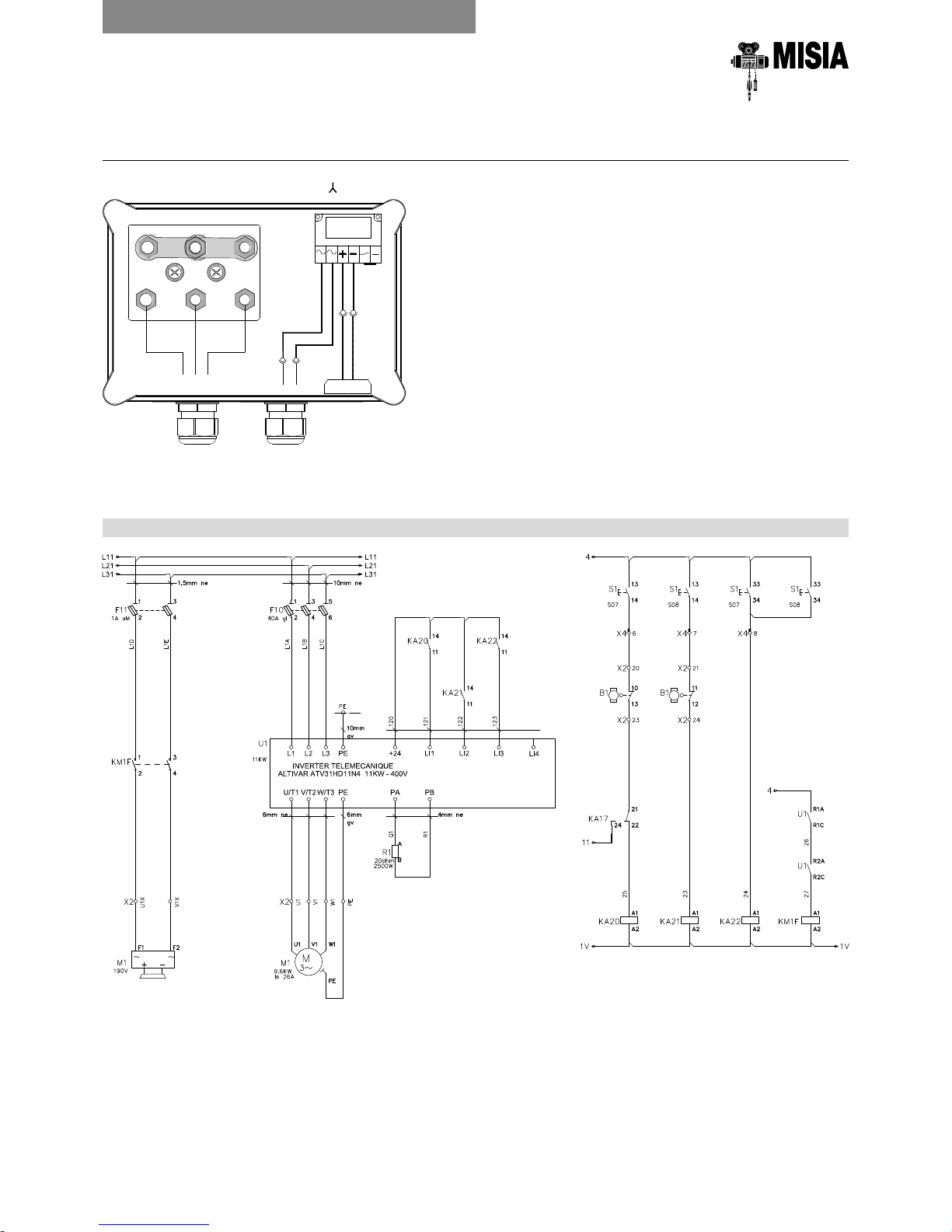
3.9.3 WIRING CONNECTIONS CYLINDRICAL MOTORS SINGLE SPEED SUITABLE FOR VFD
EXAMPLE OF VFD WIRING CONNECTION FOR LIFTING MOTOR
SINGLE SPEED MOTOR FOR VFD
FEEDING 400V 3PH
Lifting motor brake
Lifting motor
Lift
hoist
Down
hoist
Run
fast-speed
hoist
Unlock
brake motor
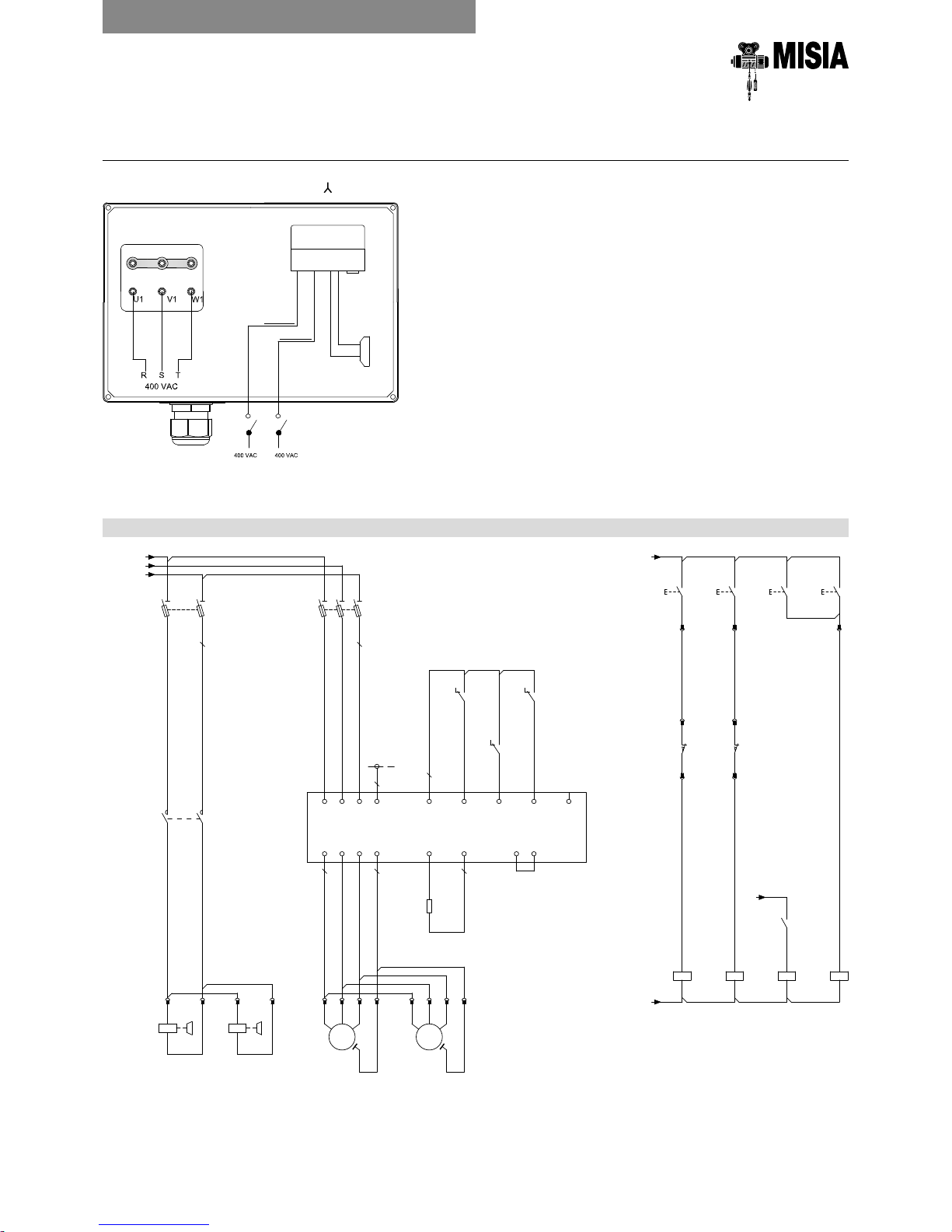
23
ELECTRIC WIRE ROPE HOIST
XM SERIES
3. INSTALLATION INSTRUCTIONS
SINGLE SPEED MOTOR FOR VFD
FEEDING 400V 3PH
3.9.3.1 C/T MOTOR FOR VFD WIRING CONNECTIONS
Separate brake feeding 400VAC monophase
Brake 180V DC
EXAMPLE OF VFD ELECTRICAL CIRCUIT
BROWN
BLUE
L2 - WHITE
L3 - VIOLET
BRAKE RECTIFIER
TYPE PBR1250
BRAKE
180V DC
INVERTER
X2D
4 5
X2D
1 2 3 PE
X2D
11
X2D
14
X2D
12
X2D
15
U2
/5.7
2,2KW
L1
U/T1L2V/T2L3W/T3PEPE
+24
PBe
LI1PBLI2
P24
LI3
STO
LI4
1
2
KM2F
/5.7
3
4
123
4
F2F
1A gI
12345
6
FU2
8A gI
1,5 mm²
BK
L2C
1,5 mm²
GNYE
0,5 mm²
BU
140
1,5 mm²
BK
U2
1,5 mm²
GNYE
1,5 mm²
BK
R2
1,5 mm²
BK
L2E
121114
KA30
/5.6
121114
KA32
/5.8
121114
KA31
/5.6
C
D
BOX1
800W
55Ω
141
142
143
Q2
V2
W2
V2X
U2X L2D
L2A
L2B
R2A
R2C
U2
/5.2
-WP01
X4
9
X4
11
X4
10
-WB04
11
12
B4
/5.6
21
22
B4
/5.6
A1
A2
KM2F
6A
A1
A2
KA30
A1
A2
KA31
A1
A2
KA32
145
34
33
32
31
30
U2
V2
M2
U1 V1 W1
PE
M2
0,55KW
In 1,9A
3~
M
-WM02 -WM02
13
14
S07
/5.7
RIGHT
13
14
S08
/5.8
LEFT
33
34
S07
/5.6
FAST
RIGHT
33
34
S08
/5.6
FAST
LEFT
X2D
9 10
X2D
6 7 8 PE
U2
V2
M3
U1 V1 W1
PE
M3
0,55KW
In 1,9A
3~
M
-WM03 -WM03
L11
400 VAC
400 VAC
400 VAC
L21
L31
4
/4.7
3
/4.8
1V
/4.8
PE
Brake motor 1
to trolley translation
Right
trolley
Left
trolley
Unlock
brake
motor
Run
fast-speed
trolley
Brake motor 1
to trolley translation
Translation motor
1 trolley
Translation motor
1 trolley
 Loading...