

Page 1
Contents
OWNER'S MANUAL.
MINI COUNTRYMAN PLUG-
IN HYBRID.
A-Z
Online Edition for Part no. 01402983594 - X/17
Page 2

Page 3

MINI
Owner's Manual for the vehicle
Thank you for choosing a MINI.
The more familiar you are with your vehicle, the better control
you will have on the road. We therefore strongly suggest:
Read this Owner's Manual before starting off in your new MINI.
Also use the Integrated Owner's Manual in your vehicle. It con‐
tains important information on vehicle operation that will help
you make full use of the technical features available in your
MINI. The manual also contains information designed to en‐
hance operating reliability and road safety, and to contribute to
maintaining the value of your MINI.
Any updates made after the editorial deadline can be found in
the appendix of the printed Owner's Manual for the vehicle.
Get started now. We wish you driving fun and inspiration with
your MINI.
Online Edition for Part no. 01402983594 - X/17
Page 4

© 2017 Bayerische Motoren Werke
Aktiengesellschaft
Munich, Germany
Reprinting, including excerpts, only with the written
consent of BMW AG, Munich.
US English ID5 X/17, 11 17 490
Printed on environmentally friendly paper, bleached
without chlorine, suitable for recycling.
Online Edition for Part no. 01402983594 - X/17
Page 5

Contents
The fastest way to find information on a partic‐
ular topic or item is by using the index, refer to
page 284.
The topics of Navigation, Entertainment, and
Communication can be called up via the follow‐
ing Owner's Manuals: Integrated Owner's
Manual in the vehicle, Online Owner's Manual,
MINI Driver's Guide app.
6 Information
AT A GLANCE
16 Cockpit
20 Central Information Display (CID)
29 Voice activation system
32 General settings
43 Owner's Manual media
47 MINI eDRIVE
49 Safety of the hybrid system
CONTROLS
52 Opening and closing
73 Settings
84 Transporting children safely
89 Driving
109 Displays
130 Lights
136 Safety
155 Driving stability control systems
159 Driving comfort
177 Climate control
186 Interior equipment
193 Storage compartments
196 Cargo area
MOBILITY
218 Charging the vehicle
226 Refueling
229 Fuel
231 Wheels and tires
246 Engine compartment
249 Engine oil
253 Coolant
255 Maintenance
257 Replacing components
267 Breakdown assistance
272 Care
REFERENCE
280 Technical data
282 Appendix
284 Everything from A to Z
DRIVING TIPS
206 Things to remember when driving
211 Saving fuel
Online Edition for Part no. 01402983594 - X/17
Page 6

Information
Information
Using this Owner's
Manual
Orientation
The fastest way to find information on a partic‐
ular topic is by using the index.
An initial overview of the vehicle is provided in
the first chapter.
Updates made after the editorial
deadline
Due to updates after the editorial deadline, dif‐
ferences may exist between the printed Own‐
er's Manual and the following Owner's Man‐
uals:
▷ Integrated Owner's Manual in the vehicle.
▷ Online Owner's Manual.
▷ MINI Motorer’s Guide App.
Notes on updates can be found in the appendix
of the printed Owner's Manual for the vehicle.
Owner's Manual for Navigation,
Entertainment, Communication
The Owner's Manual for Navigation, Entertain‐
ment, and Communication can be obtained as
printed book from the service center.
The topics of Navigation, Entertainment, and
Communication can be called up via the follow‐
ing Owner's Manuals:
▷ Integrated Owner's Manual in the vehicle.
▷ Online Owner's Manual.
▷ MINI Motorer’s Guide App.
Additional sources of in‐
formation
Dealer’s service center
A dealer’s service center will be glad to answer
questions at any time.
Internet
The Owner's Manual and general Information
about MINI, for example on technology, are
available on the Internet: www.miniusa.com.
Integrated Owner's Manual in the
vehicle
The Integrated Owner's Manual specifically de‐
scribes features and functions found in the ve‐
hicle. The Integrated Owner's Manual can be
displayed on the Control Display. Additional in‐
formation, refer to page 43.
MINI Motorer’s Guide app
The app specifically describes features and
functions found in the vehicle. The app can be
displayed on smartphones and tablets. Addi‐
tional information, refer to page 44.
Online Owner's Manual
The Online Owner's Manual specifically de‐
scribes features and functions found in the ve‐
hicle. The Online Owner's Manual can be dis‐
played in any of today's browsers. Additional
information, refer to page 45.
6
Online Edition for Part no. 01402983594 - X/17
Page 7
Symbols and displays
Symbols in the Owner's Manual
Symbol Meaning
Precautions that must be followed. To
avoid the possibility of personal injury
and serious damage to the vehicle.
Information
◄ End of a specific item of information.
Measures that can be taken to help
protect the environment.
"..." Control Display texts used to select
individual functions.
›...‹ Verbal instructions to use with the
voice activation system..
››...‹‹ Answers generated by the voice
activation system.
Action steps
Action steps to be carried out are presented as
numbered list. The steps must be carried out in
the defined order.
First action step.
1.
2. Second action step.
Enumerations
Enumerations without mandatory order or al‐
ternative possibilities are presented as list with
bullet points.
▷ First possibility.
▷ Second possibility.
Symbols on vehicle components
Refers to the relevant section of this
Owner's Manual for further information on a
particular part or assembly.
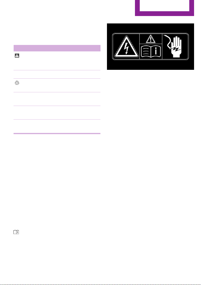
The symbols on parts of the vehicle indicate
that incorrect use of high-voltage equipment or
of orange-colored high-voltage components
results in the risk of life-threatening injury from
electric shock.
Vehicle features and op‐
tions
This Owner's Manual describes all models and
all standard, country-specific and optional
equipment that is offered in the model series.
Therefore, this Owner's Manual also describes
and illustrates features and functions that are
not available in your vehicle, for example be‐
cause of the selected optional features or the
country-specific version.
This also applies to safety-related functions and
systems.
When using these functions and systems, the
applicable laws and regulations must be ob‐
served.
For any options and equipment not described
in this Owner's Manual, refer to the Supple‐
mentary Owner's Manuals.
Your dealer’s service center is happy to answer
any questions that you may have about the
features and options applicable to your vehicle.
Online Edition for Part no. 01402983594 - X/17
7
Page 8

Information
Status of the Owner's
Manual
Basic information
The manufacturer of your vehicle pursues a
policy of constant development that is con‐
ceived to ensure that our vehicles continue to
embody the highest quality and safety stan‐
dards. In rare cases, therefore, the features de‐
scribed in this Owner's Manual may differ from
those in your vehicle.
Updates made after the editorial
deadline
Due to updates after the editorial deadline, dif‐
ferences may exist between the printed Own‐
er's Manual and the following Owner's Man‐
uals:
▷ Integrated Owner's Manual in the vehicle.
▷ Online Owner's Manual.
▷ MINI Motorer’s Guide App.
Notes on updates can be found in the appendix
of the printed Owner's Manual for the vehicle.
For Your Own Safety
Manufacturer
The manufacturer of this MINI is Bayerische
Motoren Werke Aktionengesellschaft, BMW AG.
Warranty
Your vehicle is technically configured for the
operating conditions and registration require‐
ments applying in the country of first delivery,
also known as homologation. If your vehicle is
to be operated in a different country it might
be necessary to adapt your vehicle to poten‐
tially differing operating conditions and regis‐
tration requirements. If your vehicle does not
comply with the homologation requirements in
a certain country you may not be able to lodge
warranty claims for your vehicle there. Further
information on warranty is available from a
dealer’s service center.
Maintenance and repairs
Advanced technology, e. g. the use of modern
materials and high-performance electronics,
requires suitable maintenance and repair work.
The manufacturer of your vehicle recommends
that you entrust corresponding procedures to a
MINI dealer’s service center. If you choose to
use another service facility, the manufacturer of
your vehicle recommends use of a facility that
performs work, for instance maintenance and
repair, according to MINI specifications with
properly trained personnel, referred to in this
Owner's Manual as "another qualified service
center or repair shop".
If work is performed improperly, for instance
maintenance and repair, there is a risk of sub‐
sequent damage and related safety risks.
Intended use
Follow the following when using the vehicle:
▷ Owner's Manual.
▷ Information on the vehicle. Do not remove
stickers.
▷ Technical vehicle data.
▷ The traffic, speed, and safety laws where
the vehicle is driven.
▷ Vehicle documents and statutory docu‐
ments.
8
Online Edition for Part no. 01402983594 - X/17
Parts and accessories
The manufacturer of your vehicle recommends
the use of parts and accessory products ap‐
proved by the manufacturer of the MINI.
Approved parts and accessories, and advice on
their use and installation are available from a
MINI dealer's service center.
MINI parts and accessories were tested by the
manufacturer of the MINI for their safety and
suitability in MINI vehicles.
Page 9

Information
The manufacturer of your vehicle warrants gen‐
uine MINI parts and accessories.
The manufacturer of your vehicle does not
evaluate whether each individual product from
another manufacturer can be used with MINI
vehicles without presenting a safety hazard,
even if a country-specific official approval was
issued. The manufacturer of your vehicle does
not evaluate whether these products are suita‐
ble for MINI vehicles under all usage conditions.
California Proposition 65 Warning
California laws require us to state the following
warning:
Engine exhaust and a wide variety of automo‐
bile components and parts, including compo‐
nents found in the interior furnishings in a vehi‐
cle, contain or emit chemicals known to the
State of California to cause cancer and birth de‐
fects and reproductive harm. In addition, cer‐
tain fluids contained in vehicles and certain
products of component wear contain or emit
chemicals known to the State of California to
cause cancer and birth defects or other repro‐
ductive harm. Battery posts, terminals and re‐
lated accessories contain lead and lead com‐
pounds. Wash your hands after handling. Used
engine oil contains chemicals that have caused
cancer in laboratory animals. Always protect
your skin by washing thoroughly with soap and
water.
Service and warranty
We recommend that you read this publication
thoroughly. Your vehicle is covered by the fol‐
lowing warranties:
▷ New Vehicle Limited Warranty.
▷ Rust Perforation Limited Warranty.
▷ Federal Emissions System Defect Warranty.
▷ Federal Emissions Performance Warranty.
▷ California Emission Control System Limited
Warranty.
Detailed information about these warranties is
listed in the Service and Warranty Information
Booklet for US models or in the Warranty and
Service Guide Booklet for Canadian models.
Your vehicle has been specifically adapted and
designed to meet the particular operating con‐
ditions and homologation requirements in your
country and continental region in order to de‐
liver the full driving pleasure while the vehicle is
operated under those conditions. If you wish to
operate your vehicle in another country or re‐
gion, you may be required to adapt your vehi‐
cle to meet different prevailing operating con‐
ditions and homologation requirements. You
should also be aware of any applicable war‐
ranty limitations or exclusions for such country
or region. In such case, please contact Cus‐
tomer Relations for further information.
Maintenance
Maintain the vehicle regularly to sustain the
road safety, operational reliability and the New
Vehicle Limited Warranty.
Specifications for required maintenance meas‐
ures:
▷ MINI Maintenance system.
▷ Service and Warranty Information Booklet
for US models.
▷ Warranty and Service Guide Booklet for
Canadian models.
If the vehicle is not maintained according to
these specifications, this could result in serious
damage to the vehicle. Such damage is not
covered by the MINI New Vehicle Limited War‐
ranty.
Data memory
General information
Electronic control devices are installed in the
vehicle. Some of these are necessary for the ve‐
hicle to function safely or provide assistance
during driving, for instance driver assistance
Online Edition for Part no. 01402983594 - X/17
9
Page 10

Information
systems. Furthermore, control devices facilitate
comfort or infotainment functions.
Electronic control devices contain data memo‐
ries, which are able to temporarily or perma‐
nently store information about the condition of
the vehicle, component load, maintenance re‐
quirements, technical events or faults.
This information generally records the state of a
component, a module, a system or the environ‐
ment, for instance:
▷ Operating states of system components,
e.g., fill levels, tire inflation pressure, bat‐
tery status.
▷ Status messages for the vehicle and its indi‐
vidual components, e.g., wheel rotational
speed, wheel speed, deceleration, trans‐
verse acceleration, engaged safety belt in‐
dicator.
▷ Malfunctions and faults in important system
components, for instance lights and brakes.
▷ Information on vehicle-damaging events.
▷ Responses by the vehicle to special situa‐
tions such as airbag deployment or en‐
gagement of the stability control systems.
▷ Ambient conditions, e.g., temperature, rain
sensor signals.
The data is required to perform the control de‐
vice functions. Furthermore, it also serves to
recognize and correct malfunctions, and helps
the vehicle manufacturer to optimize vehicle
functions. The majority of this data is transient
and is only processed within the vehicle itself.
Only a small proportion of the data is stored in
event or fault memories and, if needed, in the
vehicle key.
Reading out data
When servicing, for instance during repairs,
service processes, warranty cases, and quality
assurance measures, this technical information
can be read out from the vehicle together with
the vehicle identification number. A dealer’s
service center or another qualified service cen‐
ter or repair shop can read out the information.
The socket for OBD Onboard Diagnosis re‐
quired by law in the vehicle is used to read out
the data. The data is collected, processed, and
used by the relevant organizations in the serv‐
ice network. The data documents the technical
conditions of the vehicle, helps in locating
faults and improving quality, and is transferred
to the vehicle manufacturer, if needed.
Furthermore, the manufacturer has product
monitoring duties to meet in line with product
liability law. To fulfill these duties, the vehicle
manufacturer needs technical data from the
vehicle. Fault and event memories in the vehi‐
cle can be reset when a dealer’s service center
or another qualified service center or repair
shop performs repair or servicing work.
Data on the scope of servicing work performed
and maintenance records are stored in the ve‐
hicle by means of the service history and trans‐
ferred to the vehicle manufacturer. The vehicle
owner can contact a dealer's service center to
object to the data being stored and transferred
to the vehicle manufacturer. This objection ap‐
plies for as long as the vehicle owner remains
the proprietor of the vehicle.
Data entry and data transfer into the
vehicle
General information
Depending on the vehicle equipment, some
data can be transferred into the vehicle when
using comfort and infotainment functions,
for instance:
▷ Multimedia data such as music, films or
photos for playback in an integrated multi‐
media system.
▷ Address book data for use in conjunction
with an integrated hands-free system or an
integrated navigation system.
▷ Entered navigation destinations.
▷ Data on the use of Internet services.
10
Online Edition for Part no. 01402983594 - X/17
Page 11

Information
This data can be stored locally in the vehicle or
is found on a device that has been connected
to the vehicle, e.g., a smartphone, USB stick or
MP3 player. If this data is stored in the vehicle,
it can be deleted at any time. This data is only
transmitted to third parties if expressly desired.
This depends on the personal settings selected
for using online services.
Depending on the vehicle equipment, the fol‐
lowing comfort and individual settings can be
stored in the vehicle and modified at any time,
for instance:
▷ Settings for the seat and steering wheel po‐
sitions.
▷ Suspension and climate control settings.
▷ Individual settings, for instance lighting in
the car's interior.
Control via mobile devices
Depending on the vehicle equipment, mobile
devices connected to the vehicle, for instance
smartphones, can be controlled via the vehicle
control elements. The sound and picture from
the mobile device can be played back and dis‐
played through the multimedia system. Certain
information is transferred to the mobile device
at the same time. Depending on the type of
connection, this includes, for instance position
data and other general vehicle information.
This optimizes the way in which selected apps,
for instance navigation or music playback,
work.
There is no further interaction between the mo‐
bile device and the vehicle, for instance active
access to vehicle data. How the data will be
processed further is determined by the provider
of the particular app being used. The extent of
the possible settings depends on the respective
app and the operating system of the mobile
device.
Services
General information
If the vehicle has a wireless network connec‐
tion, this enables data to be exchanged be‐
tween the vehicle and other systems. The wire‐
less network connection is realized via an invehicle transmitter and receiver unit or via
personal mobile devices brought into the vehi‐
cle, for instance smartphones. This wireless net‐
work connection enables 'online functions' to
be used. These include online services and apps
supplied by the vehicle manufacturer or by
other providers.
Services from the vehicle manufacturer
Where online services from the vehicle manu‐
facturer are concerned, the corresponding
functions are described in the appropriate
place, for instance the Owner's Manual or man‐
ufacturer's website. The relevant legal informa‐
tion pertaining to data protection is provided
there too. Personal data may be used to per‐
form online services. Data is exchanged over a
secure connection, for instance with the IT sys‐
tems of the vehicle manufacturer intended for
this purpose. Any collection, processing, and
use of personal data above and beyond that
needed to provide the services must always be
based on a legal permission, contractual ar‐
rangement or consent.
In addition, the vehicle manufacturer evaluates
anonymized information on transport infra‐
structure and how the infotainment system is
used. This information cannot be traced back to
individual vehicles or people. Evaluating the
data enables the manufacturer to further im‐
prove its products or services, for instance by
incorporating the most up-to-date traffic bulle‐
tins. The data transfer feature can be deacti‐
vated in the vehicle. Certain services and func‐
tions, some of which are subject to a charge,
can be deactivated by the driver. It is also pos‐
sible to activate or deactivate the data connec‐
tion as a whole. That is, with the exception of
Online Edition for Part no. 01402983594 - X/17
11
Page 12
Information
functions and services required by law such as
Assist systems.
Services from other providers
When using online services from other provid‐
ers, these services are the responsibility of the
relevant provider and subject to their data pri‐
vacy conditions and terms of use. The vehicle
manufacturer has no influence on the content
exchanged during this process. Information on
the way in which personal data is collected and
used in relation to services from third parties,
the scope of such data, and its purpose, can be
obtained from the relevant service provider.
Event Data Recorder EDR
This vehicle is equipped with an event data re‐
corder EDR. The main purpose of an EDR is to
record, in certain crash or near crash-like situa‐
tions, such as an air bag deployment or hitting
a road obstacle, data that will assist in under‐
standing how a vehicle’s systems performed.
The EDR is designed to record data related to
vehicle dynamics and safety systems for a short
period of time, typically 30 seconds or less.
The EDR in this vehicle is designed to record
such data as:
▷ How various systems in your vehicle were
operating.
▷ Whether or not the driver and passenger
safety belts were fastened.
▷ How far, if at all, the driver was depressing
the accelerator and/or brake pedal.
▷ How fast the vehicle was traveling.
This data can help provide a better understand‐
ing of the circumstances in which crashes and
injuries occur.
EDR data is recorded by your vehicle only if a
nontrivial crash situation occurs; no data is re‐
corded by the EDR under normal driving condi‐
tions and no personal data, for instance name,
gender, age, and crash location, are recorded.
However, other parties, such as law enforce‐
ment, could combine the EDR data with the
type of personally identifying data routinely ac‐
quired during a crash investigation.
To read data recorded by an EDR, special
equipment is required, and access to the vehi‐
cle or the EDR is needed. In addition to the ve‐
hicle manufacturer, other parties, such as law
enforcement, that have the special equipment,
can read the information if they have access to
the vehicle or the EDR.
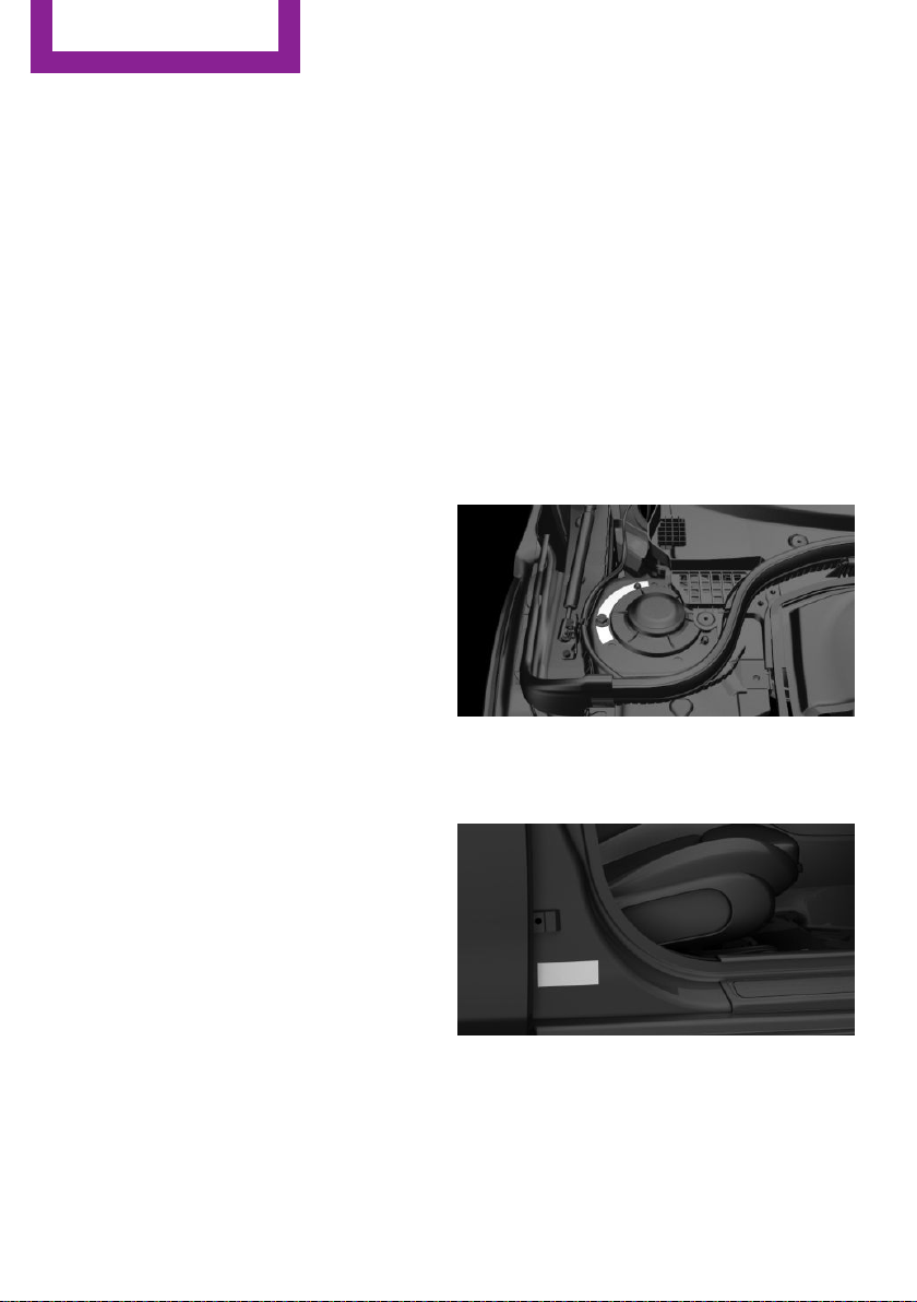
Vehicle identification
number
The vehicle identification number can be found
in the engine compartment, on the right-hand
side of the vehicle.
The vehicle identification number can be found
on the type label, on the right-hand side of the
vehicle.
12
Online Edition for Part no. 01402983594 - X/17
Page 13

The vehicle identification number can also be
found behind the windshield.
Reporting safety defects
For US customers
The following only applies to vehicles owned
and operated in the US.
If you believe that your vehicle has a defect
which could cause a crash or could cause injury
or death, you should immediately inform the
National Highway Traffic Safety Administration
NHTSA, in addition to notifying MINI of North
America, LLC, P.O. Box 1227, Westwood, New
Jersey 07675-1227, Telephone
1-800-831-1117.
If NHTSA receives similar complaints, it may
open an investigation, and if it finds that a
safety defect exists in a group of vehicles, it
may order a recall and remedy campaign.
However, NHTSA cannot become involved in
individual problems between you, your dealer,
or MINI of North America, LLC.
To contact NHTSA, you may call the Vehicle
Safety Hotline toll-free at 1-888-327-4236
(TTY: 1-800-424-9153); go to http://www.safe‐
rcar.gov; or write to: Administrator, NHTSA, 400
Seventh Street, SW., Washington, DC 20590.
You can also obtain other information about
motor vehicle safety from http://www.safe‐
rcar.gov
Information
For Canadian customers
Canadian customers who wish to report a
safety-related defect to Transport Canada, De‐
fect Investigations and Recalls, may call the
toll-free hotline 1-800-333-0510. You can also
obtain other information about motor vehicle
safety from http://www.tc.gc.ca/roadsafety.
Online Edition for Part no. 01402983594 - X/17
13
Page 14
WATCH ME.
Online Edition for Part no. 01402983594 - X/17
Page 15

AT A GLANCE
CONTROLS
DRIVING TIPS
MOBILITY
REFERENCE
Online Edition for Part no. 01402983594 - X/17
Page 16
AT A GLANCE
Cockpit
Cockpit
Vehicle features and op‐
tions
This chapter describes all standard, countryspecific and optional features offered with the
series. It also describes features that are not
necessarily available in your vehicle, e. g., due
to the selected options or country versions. This
also applies to safety-related functions and sys‐
tems. When using these functions and systems,
the applicable laws and regulations must be
observed.
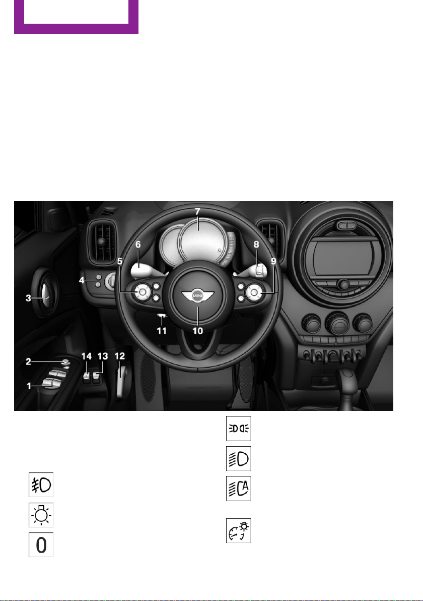
In the vicinity of the steering wheel
1 Power windows 69
2 Exterior mirror operation 81
3 Buttons of the central locking system 57
4 Lights
Front fog lights 133
Light switch 130
Lights off
Daytime running lights 132
16
Online Edition for Part no. 01402983594 - X/17
Parking lights 130
Low beams 130
Automatic headlight control 131
Cornering light 132
High-beam Assistant 132
Instrument lighting 133
5 Steering wheel buttons, left
Page 17
Cockpit
AT A GLANCE
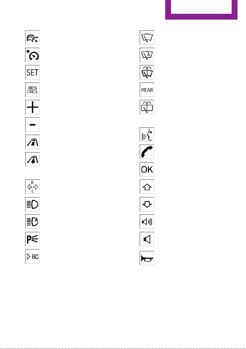
Camera-based cruise control on/
off 159
Cruise control on/off 165
Cruise control: store speed
Pausing, continuing cruise control
Cruise control: increase speed
Cruise control: reduce speed
Camera-based cruise control: re‐
duce distance
Camera-based cruise control: in‐
crease distance
6 Steering column stalk, left
Turn signal 97
High beams, head‐
light flasher 97
Windshield wipers 101
Rain sensor 102
Cleaning windows 99
Rear window wiper 100
Clean the rear window 100
9 Steering wheel buttons, right
Voice activation 29
Telephone
Confirm the selection 121
Move selection up 121
Move selection down 121
High-beam Assistant 132
Canada: roadside parking
light 131
Onboard Computer 121
7 Instrument cluster 109
8 Steering column stalk, right
Online Edition for Part no. 01402983594 - X/17
Increase volume
Reduce volume
10 Horn, entire surface
11 Adjust the steering wheel 83
12 Unlock hood 247
13 Operate the tailgate 60
17
Page 18
AT A GLANCE
14 Tank vent 226
Cockpit
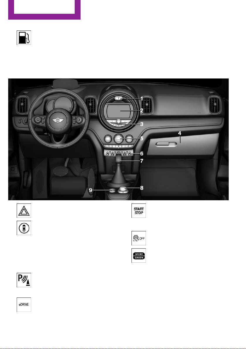
In the vicinity of the center console
1 Hazard warning system 267
Intelligent Safety 146
2 Control Display 20
3 Radio/Multimedia
4 Glove compartment 193
5 Climate control 177
6 PDC Park Distance Control 167
Rearview camera 170
Parking assistant 173
eDRIVE 92
18
Online Edition for Part no. 01402983594 - X/17
Starting/stopping the engine,
switching drive-ready state
modes and the ignition on/
off 89
DSC Dynamic Stability Con‐
trol 155
MINI Driving Modes switch 157
7 Steptronic transmission selector lever 105
8 Controller with buttons 21
9 Parking brake 95
Page 19
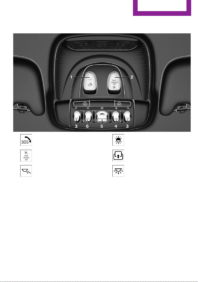
In the vicinity of the roofliner
Cockpit
AT A GLANCE
1 Emergency Request
2 Indicator light, front-seat passen‐
ger airbag 139
3 Reading lights 134
4 Ambient light 134
5 Panoramic glass sunroof 70
6 Interior lights 134
Online Edition for Part no. 01402983594 - X/17
19
Page 20
AT A GLANCE
Central Information Display (CID)
Central Information Display (CID)
Vehicle features and op‐
tions
This chapter describes all standard, countryspecific and optional features offered with the
series. It also describes features that are not
necessarily available in your vehicle, e. g., due
to the selected options or country versions. This
also applies to safety-related functions and sys‐
tems. When using these functions and systems,
the applicable laws and regulations must be
observed.
Concept
The Central Information Display (CID) combines
the functions of a multitude of switches. These
functions can be operated via the Controller or
touchscreen.
Safety information
WARNING
Operating the integrated information sys‐
tems and communication devices while driving
can distract from traffic. It is possible to lose
control of the vehicle. There is a risk of an acci‐
dent. Only use the systems or devices when the
traffic situation allows. If necessary, stop and
use the systems and devices while the vehicle is
stationary.◀
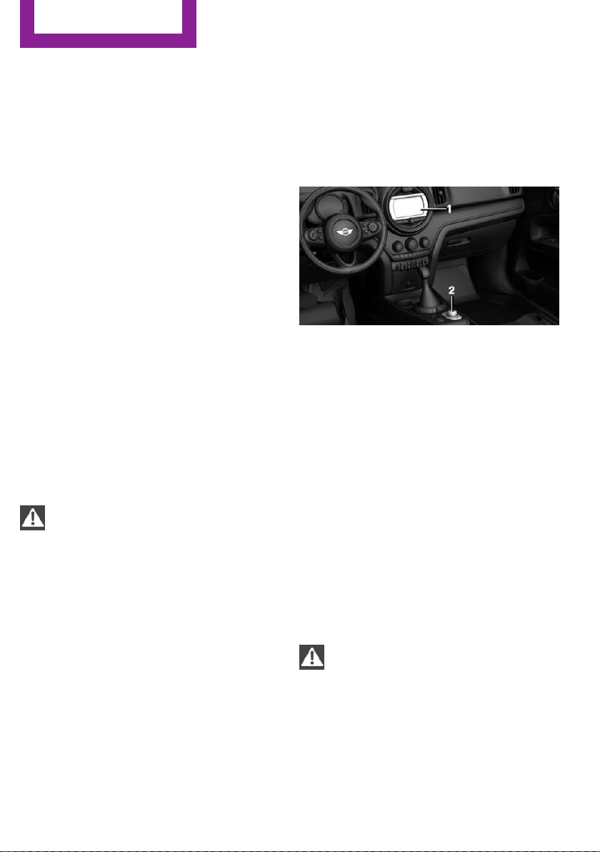
Control elements
Overview
1 Control Display with touchscreen
2 Controller with buttons and, depending on
the equipment version, with touchpad
Control Display
General information
To clean the Control Display, follow the care in‐
structions, refer to page 275.
In the case of very high temperatures on the
Control Display, for instance due to intense so‐
lar radiation, the brightness may be reduced
down to complete deactivation. Once the tem‐
perature is reduced, for instance through shade
or air conditioning, the normal functions are re‐
stored.
Safety information
NOTE
Objects in the area in the front of the
Control Display can shift and damage the Con‐
trol Display. There is a risk of damage to prop‐
erty. Do not place objects in the area in front of
the Control Display.◀
20
Switching on
Switch on the ignition.
1.
Online Edition for Part no. 01402983594 - X/17
Page 21

2. Press the Controller.
Switching off
Central Information Display (CID)
AT A GLANCE
1.
2. "Turn off control display"
Press button.
Controller with navigation system
General information
The buttons can be used to open the menus di‐
rectly. The Controller can be used to select
menu items and enter the settings.
Some functions of the Central Information Dis‐
play (CID) can be operated using the touchpad
on the Controller, refer to page 26:
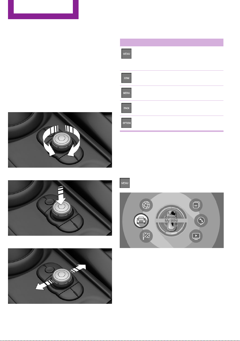
Operation
▷ Turn.
▷ Move in four directions.
Buttons on the Controller
Button Function
Press once: call up main menu.
Press twice: open recently used me‐
nus.
Open the Communication menu.
▷ Press.
Open the Media/Radio menu.
Open destination input menu for navi‐
gation.
Open navigation map.
Open the previous display.
Open the Options menu.
Online Edition for Part no. 01402983594 - X/17
21
Page 22
AT A GLANCE
Central Information Display (CID)
Controller without navigation system
General information
The buttons can be used to open the menus di‐
rectly. The Controller can be used to select
menu items and enter the settings.
Some functions of the Central Information Dis‐
play (CID) can be operated using the touchpad
on the Controller, refer to page 26:
Operation
▷ Turn.
▷ Press.
Buttons on the Controller
Button Function
Press once: call up main menu.
Press twice: open recently used me‐
nus.
Open the Communication menu.
Open the Media/Radio menu.
Open the previous display.
Open the Options menu.
Operating with the Con‐
troller
Opening the main menu
Press button.
▷ Move in two directions.
22
The main menu is displayed.
All Central Information Display (CID) functions
can be called up via the main menu.
Online Edition for Part no. 01402983594 - X/17
Page 23
Central Information Display (CID)
AT A GLANCE
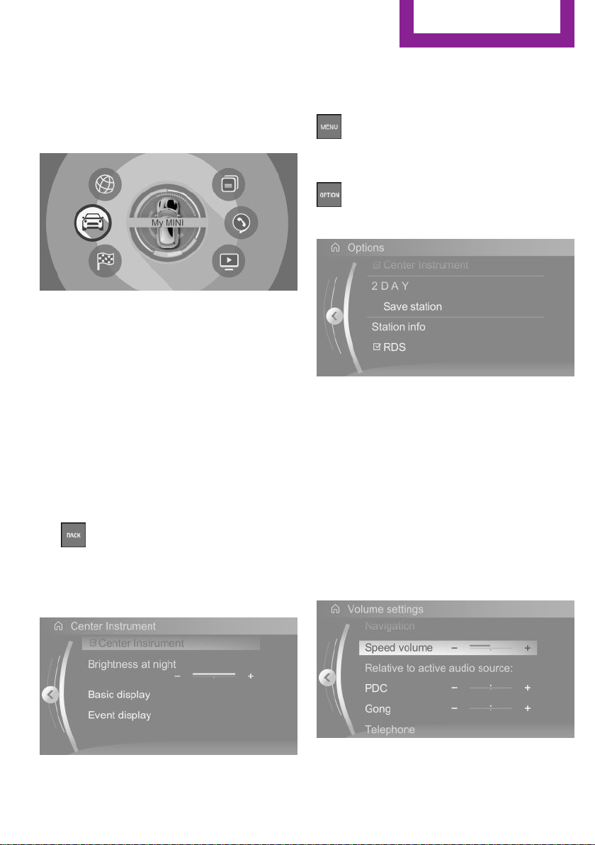
Selecting menu items
Highlighted menu items can be selected.
1. Turn the Controller until the desired menu
item is highlighted.
2. Press the Controller.
Menu items in the Owner's Manual
In the Owner's Manual, menu items that can be
selected are set in quotation marks, for in‐
stance "System settings".
Changing between displays
After a menu item is selected, for instance
"System settings", a new display appears.
▷ Move the Controller to the left.
Closes the current display and shows the
previous display.
▷
▷ Move the Controller to the right.
Press button.
The previous display opens.
New display is opened.
Opening recently used menus
The recently used menus can be displayed.
Press button twice.
Opening the Options menu
Press button.
The "Options" menu is displayed.
The Options menu consists of various areas:
▷ Screen settings, for instance "Split screen".
▷ Control options for the selected main
menu, for instance for "Media/Radio".
▷ If applicable, further operating options for
the selected menu, for instance "Save
station".
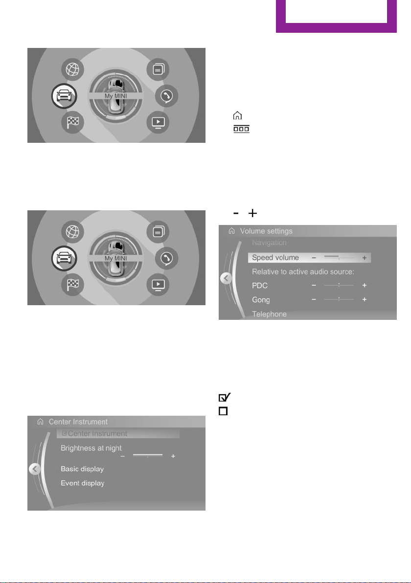
Changing settings
Select a field.
1.
2. Turn the Controller until the desired setting
is displayed.
The arrow indicates that additional displays can
be opened.
Online Edition for Part no. 01402983594 - X/17
3. Press the Controller.
23
Page 24
AT A GLANCE
Central Information Display (CID)
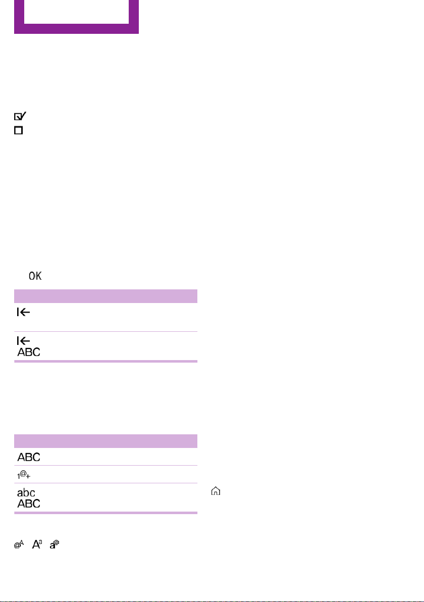
Activating/deactivating the functions
Several menu items are preceded by a check‐
box. It indicates whether the function is acti‐
vated or deactivated. Selecting the menu item
activates or deactivates the function.
Function is activated.
Function is deactivated.
Entering letters and numbers
General information
Letters and numbers can be entered via the
Controller.
The keyboard's display changes automatically.
Input
Turn the Controller: select letters or num‐
1.
bers.
2. : confirm entry.
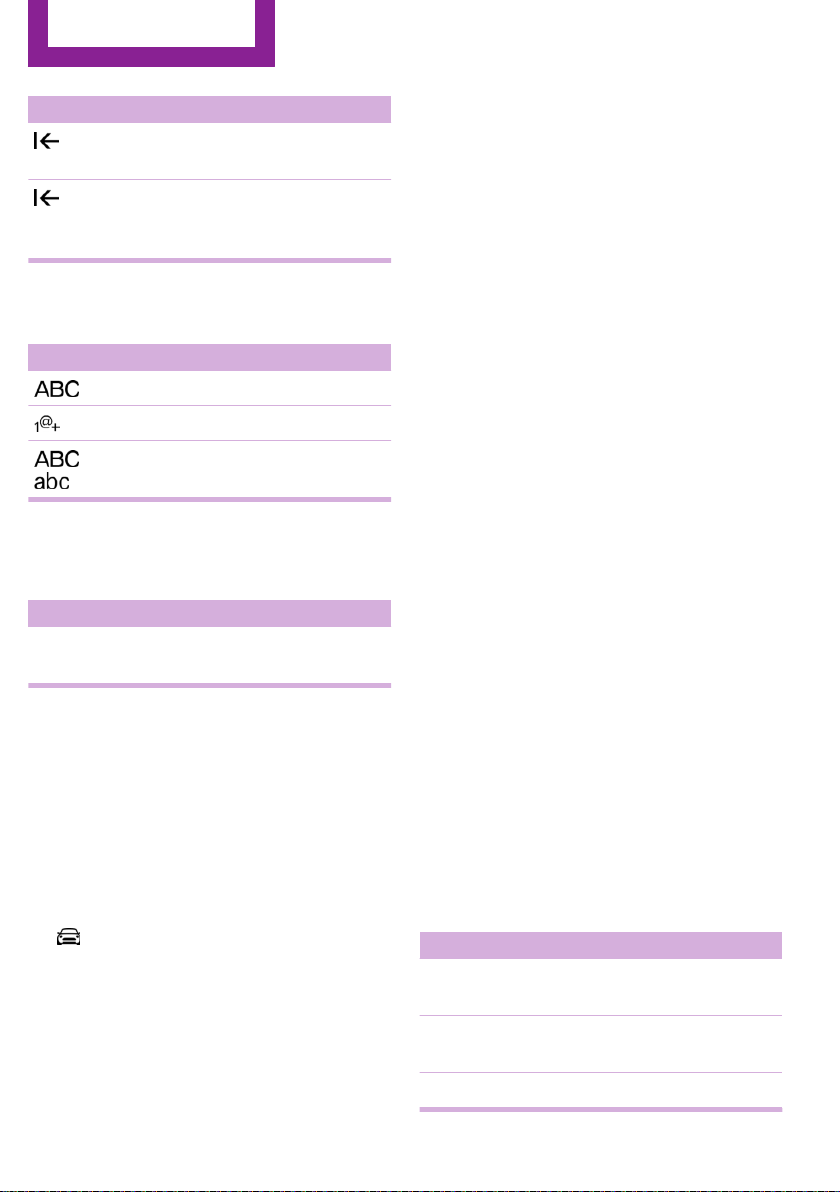
Symbol Function
Press the Controller: delete let‐
ters or number.
or
Hold the Controller down: delete
all letters or numbers.
Switching between upper/lower case,
numbers and characters
Depending on the menu, you can switch be‐
tween entering upper and lower case letters
and numbers:
Symbol Function
Enter the letters.
Entry comparison
When entering names and addresses, the
choice is narrowed down with every letter en‐
tered and letters may be added automatically.
Entries are continuously compared with data
stored in the vehicle.
▷ Only those letters are offered during entry
for which data is available.
▷ Destination search: place names can be en‐
tered in all languages that are available on
the Control Display.
Using alphabetical lists
For alphabetical lists with more than 30 entries,
the letters for which there is an entry are dis‐
played at the left edge.
Turn the Controller to the left or right
1.
quickly.
All letters for which there are entries are
displayed on the left edge.
2. Select the first letter of the desired entry.
The first entry of the selected letter is dis‐
played.
Operating via touch‐
screen
General information
The Control Display is equipped with a touch‐
screen.
Touch screen with your fingers. Do not use any
objects.
Enter the numbers.
or
Without navigation system
Select the symbol.
Change between capital and
lower-case letters.
24
Opening the main menu
Tap on symbol.
Online Edition for Part no. 01402983594 - X/17
Page 25
Central Information Display (CID)
▷ Swipe to the left.
▷ Tap on symbol.
New display is opened.
Opening recently used menus
1. Tap on symbol.
2. Tap on symbol.
AT A GLANCE
All Central Information Display (CID) functions
can be called up via the main menu.
Selecting menu items
Tap desired menu item.
Menu items in the Owner's Manual
In the Owner's Manual, menu items that can be
selected are set in quotation marks, for in‐
stance "System settings".
Changing between displays
After a menu item is selected, a new display
opens.
Changing settings
Settings such as volumes can be changed via
the touchscreen.
▷ Slide in the selected field to the right or left,
until the desired setting is displayed.
▷ , Tap on symbol.
Activating/deactivating the functions
Several menu items are preceded by a check‐
box. It indicates whether the function is acti‐
vated or deactivated. Selecting the menu item
activates or deactivates the function.
Function is activated.
Function is deactivated.
Entering letters and numbers
The arrow indicates that additional displays can
be opened.
Online Edition for Part no. 01402983594 - X/17
General information
Letters and numbers can be entered using the
Controller or the touchscreen.
The keyboard's display changes automatically.
25
Page 26
AT A GLANCE
Central Information Display (CID)
Symbol Function
Tapping the symbol: delete the letter
or number.
Tapping and holding the symbol for
an extended period: delete all letters
or numbers.
Switching between upper/lower case,
numbers and characters
Symbol Function
Enter the letters.
Enter the numbers.
or Change between capital and
lower-case letters.
Operating navigation map
The navigation map can be moved with the
touchscreen.
Function Operation
Enlarge/shrink
map.
Drag in or out with the fin‐
gers.
Touchpad
General information
Some functions of the Central Information Dis‐
play (CID) can be operated using the touchpad
on the Controller:
Selecting functions
"My MINI"
1.
2. "System settings"
3. "Touchpad"
4. Select the desired function.
▷ "Speller": enter letters and numbers.
▷ "Map": using the map.
▷ "Search fields": write letters without se‐
lecting the list field.
▷ "Audio feedback": pronounces entered
letters and numbers.
Entering letters and numbers
Entering letters requires some practice at the
beginning. When entering, pay attention to the
following:
▷ The system distinguishes between upper
and lower-case letters and numbers. To
make entries, it may be necessary to
change between upper and lower-case let‐
ters, numbers and characters, refer to
page 24.
▷ Enter characters as they are displayed on
the Control Display.
▷ Always enter associated characters, such as
accents or periods so that the letter can be
clearly recognized. The set language deter‐
mines what input is possible. Where neces‐
sary, enter special characters via the Con‐
troller.
▷ To delete a character, swipe to the left on
the touchpad.
▷ To enter a blank space, swipe to the right in
the center of the touchpad.
▷ To enter a hyphen, swipe to the right in the
upper area of the touchpad.
▷ To enter an underscore, swipe to the right
in the lower area of the touchpad.
Using the map
The map in the navigation system can be
moved via the touchpad.
Function Operation
Move map. Swipe in the appropriate di‐
rection.
Enlarge/shrink
map.
Display menu. Tap once.
Drag in or out on the touch‐
pad with fingers.
26
Online Edition for Part no. 01402983594 - X/17
Page 27
Central Information Display (CID)
AT A GLANCE
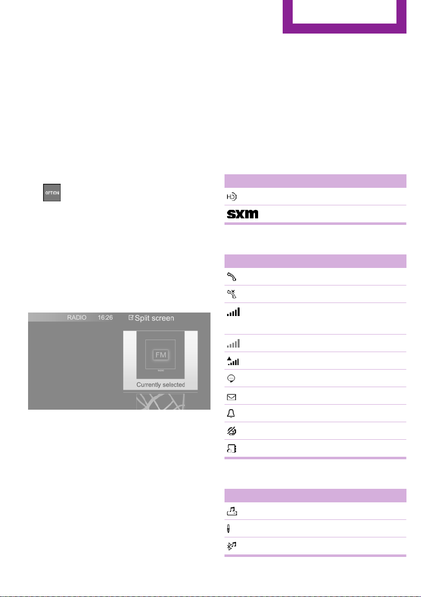
Split screen
General information
Additional information can be displayed on the
right side of the split screen, for instance infor‐
mation from the Onboard Computer.
In the divided screen view, the so-called split
screen, this information remains visible even
when switching to another menu.
Switching the split screen on/off
1.
2. "Split screen"
Selecting the display
The display can be selected in menus, where
the split screen is supported.
1.
2. Press the Controller.
Press button.
Move the Controller to the right until the
split screen is selected.
Status information
General information
The status field can be found in the upper area
of the Control Display. Status information is dis‐
played in the form of symbols.
Status field symbols
Radio
Symbol Meaning
HD Radio station is being received.
Satellite radio is switched on.
Telephone
Symbol Meaning
Incoming or outgoing call.
Missed call.
Signal strength of cellular network.
Symbol flashes: network search.
Cellular network is not available.
3. Select the desired setting.
Specifying the number of displays
It is possible to specify the number of displays.
Move the Controller to the right until the
1.
split screen is selected.
2. Press the Controller.
3. "Personalize menu"
4. Select the desired setting.
5. Move the Controller to the left.
Online Edition for Part no. 01402983594 - X/17
Roaming is active.
SMS text message received.
Message received.
Reminder.
Sending not possible.
Contacts are loaded.
Entertainment
Symbol Meaning
Music collection.
AUX-IN port.
Bluetooth audio.
27
Page 28
AT A GLANCE
Central Information Display (CID)
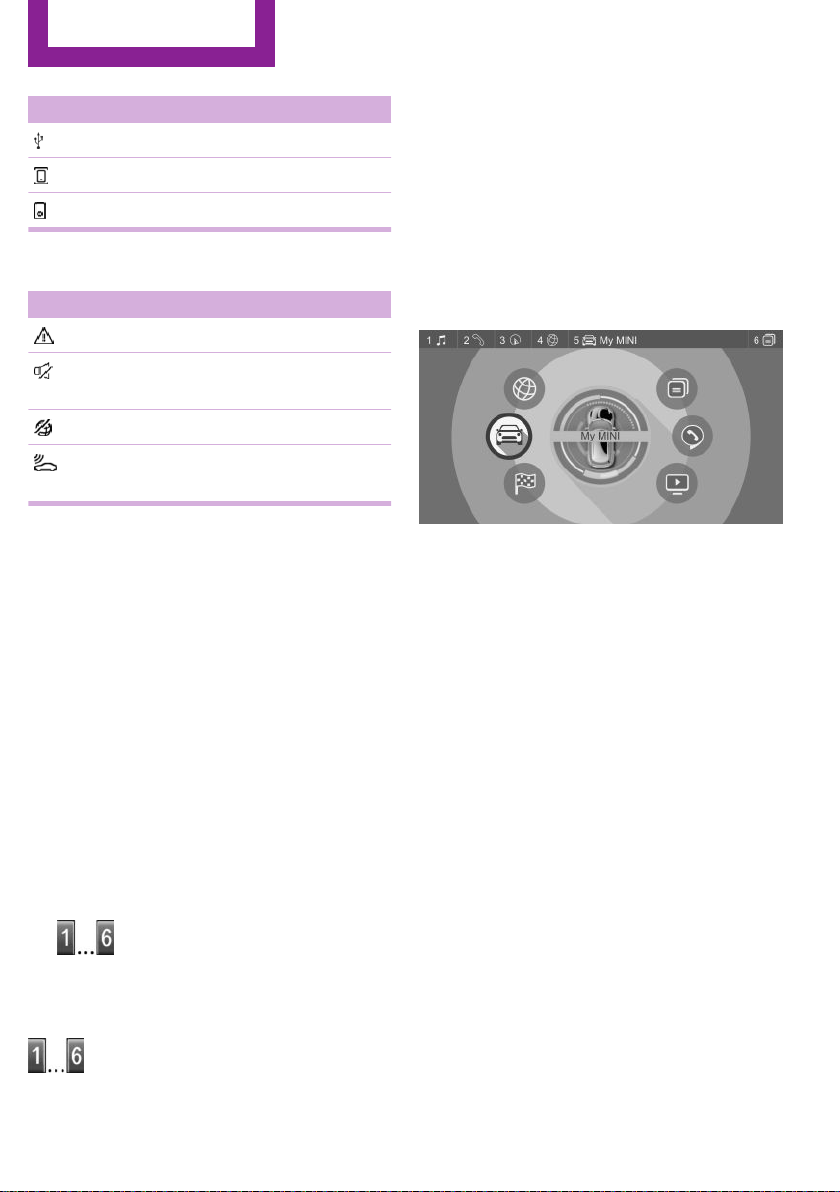
Symbol Meaning
USB audio interface.
Mobile phone audio interface.
iPod.
Additional symbols
Symbol Meaning
Check Control message.
The sound output has been switched
off.
Encrypted connection not active.
Request for the current vehicle posi‐
tion.
Programmable memory buttons
General information
The Central Information Display (CID) functions
can be stored on the programmable memory
buttons and called up directly, for instance
radio stations, navigation destinations, phone
numbers and menu entries.
Settings are stored for the driver profile cur‐
rently used.
The function will work immediately. This
means, for instance that the number is dialed
when a phone number is selected.
Displaying the key assignment
Touch buttons with finger. Do not wear gloves
or use objects.
The button assignment is displayed at the top
edge of screen.
Deleting the button assignments
Press buttons 1 and 6 simultaneously for
1.
approx. 5 seconds.
2. "OK"
Storing a function
Select the function via the Central Informa‐
1.
tion Display (CID).
2.
Press and hold the desired button,
until a signal sounds.
Running a function
Press button.
28
Online Edition for Part no. 01402983594 - X/17
Page 29

Voice activation system
Voice activation system
AT A GLANCE
Vehicle features and op‐
tions
This chapter describes all standard, countryspecific and optional features offered with the
series. It also describes features that are not
necessarily available in your vehicle, e. g., due
to the selected options or country versions. This
also applies to safety-related functions and sys‐
tems. When using these functions and systems,
the applicable laws and regulations must be
observed.
Concept
Most functions displayed on the Control Display
can be operated by voice commands via the
voice activation system. The system supports
you with announcements during input.
General information
▷ Functions that can only be used when the
vehicle is stationary can only be operated
via the voice activation system to a limited
extent.
▷ The system uses a special microphone on
the driver's side.
▷ ›...‹ in the Owner's Manual denotes verbal
instructions to use with the voice activation
system.
▷ Say the commands, numbers, and letters
smoothly and with normal volume, empha‐
sis, and speed.
▷ Always say commands in the language of
the voice activation system.
Functional requirements
Via the Control Display, set a language that is
also supported by the voice activation system
so that the spoken commands can be identi‐
fied.
To set the language, refer to page 32.
Using the voice activa‐
tion system
Activating the voice activation system
1. Press button on the steering wheel.
2. Wait for the signal.
3. Say the command.
This symbol in the instrument cluster indi‐
cates that the voice activation system is active.
If no other commands are available, operate
the function via the Central Information Display
(CID).
Terminating the voice activation
system
Press the button on the steering wheel
or ›Cancel‹.
Possible commands
General information
Most menu items on the Control Display can be
voiced as commands.
Commands from other menus can also be spo‐
ken.
You may select list entries such as phone list
entries via voice activation. Read these list en‐
Online Edition for Part no. 01402983594 - X/17
29
Page 30

AT A GLANCE
Voice activation system
tries out loud exactly as they are shown in the
respective list.
Displaying possible commands
The following is displayed in the top area of the
Control Display:
▷ Some possible commands for the current
menu.
▷ Some possible commands from other me‐
nus.
▷ Status of the voice recognition.
▷ Encrypted connection is not available.
Help on the voice activation system
▷ To have information on the operating prin‐
ciple of the voice activation system read
out loud: ›General information on voice
control‹.
▷ To have help for the current menu read out
loud: ›Help‹.
Example: opening the tone settings
The commands of the menu items are spoken
just as they are selected via the Controller.
Switch on the Entertainment sound output,
1.
if needed.
2.
3. ›Media and radio‹
4. ›Tone‹
Press button on the steering wheel.
Settings
Setting the voice dialog
You can set the system to use standard dialog
or a short version.
The short version of the voice dialog plays back
short messages in abbreviated form.
1. "My MINI"
2. "System settings"
3. "Language"
4. "Speech mode:"
5. Select the desired setting.
Selecting the input language
For some languages, the input language can be
selected.
"My MINI"
1.
2. "System settings"
3. "Language"
4. "Voice control:"
5. Select the desired setting.
Activating voice recognition via the
server
The voice recognition feature via the server
provides a dictation function and a natural
method of entering destinations while improv‐
ing the quality of voice recognition. To use the
functions, data is transmitted to a service pro‐
vider via an encrypted connection and stored
locally there.
"My MINI"
1.
2. "System settings"
3. "Language"
4. "Server speech recognition"
Speaking during voice output
It is possible to answer during inquiries of the
voice activation system. The function can be
deactivated if inquiries are often undesirably
interrupted, for instance due to background
noise or talking.
"My MINI"
1.
2. "System settings"
30
Online Edition for Part no. 01402983594 - X/17
Page 31

Voice activation system
3. "Language"
4. "Speaking during voice output"
Adjusting the volume
Turn the volume button during the spoken in‐
structions until the desired volume is set.
▷ The volume remains constant even if the
volume of other audio sources is changed.
▷ The volume is stored for the profile cur‐
rently used.
Information on Emer‐
gency Requests
Do not use the voice activation system to ini‐
tiate an Emergency Request. In stressful situa‐
tions, the voice and vocal pitch can change.
This can unnecessarily delay the establishment
of a phone connection.
AT A GLANCE
Environmental condi‐
tions
▷ Keep the doors, windows, and glass sun‐
roof closed to prevent noise interference.
▷ Avoid making other noise in the vehicle
while speaking.
Online Edition for Part no. 01402983594 - X/17
31
Page 32

AT A GLANCE
General settings
General settings
Vehicle features and op‐
tions
This chapter describes all standard, countryspecific and optional features offered with the
series. It also describes features that are not
necessarily available in your vehicle, e. g., due
to the selected options or country versions. This
also applies to safety-related functions and sys‐
tems. When using these functions and systems,
the applicable laws and regulations must be
observed.
Language
Setting the language
Via the Central Information Display (CID):
"My MINI"
1.
2. "System settings"
3. "Language"
4. "Language:"
5. Select the desired setting.
The setting is stored for the driver profile cur‐
rently used.
Setting the voice dialog
Voice dialog for the voice activation system, re‐
fer to page 30.
Time
4. "Time zone:"
5. Select the desired setting.
The setting is stored for the driver profile cur‐
rently used.
Setting the time
Via the Central Information Display (CID):
1. "My MINI"
2. "System settings"
3. "Date and time"
4. "Time:"
5. Turn the Controller until the desired hours
are displayed.
6. Press the Controller.
7. Turn the Controller until the desired mi‐
nutes are displayed.
8. Press the Controller.
The setting is stored for the driver profile cur‐
rently used.
Setting the time format
Via the Central Information Display (CID):
"My MINI"
1.
2. "System settings"
3. "Date and time"
4. "Time format:"
5. Select the desired setting.
The setting is stored for the driver profile cur‐
rently used.
Setting the time zone
Via the Central Information Display (CID):
"My MINI"
1.
2. "System settings"
3. "Date and time"
32
Online Edition for Part no. 01402983594 - X/17
Page 33

General settings
AT A GLANCE
Date
Setting the date
Via the Central Information Display (CID):
1. "My MINI"
2. "System settings"
3. "Date and time"
4. "Date:"
5. Turn the Controller until the desired day is
displayed.
6. Press the Controller.
7. Make the settings for the month and year.
The setting is stored for the driver profile cur‐
rently used.
Setting the date format
Via the Central Information Display (CID):
"My MINI"
1.
2. "System settings"
3. "Date and time"
4. "Date format:"
5. Select the desired setting.
The setting is stored for the driver profile cur‐
rently used.
Setting the units of measurement
You can set the units of measurement for some
values, for example, fuel consumption, distan‐
ces and temperature.
Via the Central Information Display (CID):
"My MINI"
1.
2. "System settings"
3. "Units"
4. Select the desired menu item.
5. Select the desired setting.
The setting is stored for the driver profile cur‐
rently used.
Activating/deactivating popup windows
For some functions, popup windows are dis‐
played automatically on the Control Display.
Some of these popup windows can be acti‐
vated or deactivated.
Via the Central Information Display (CID):
1. "My MINI"
2. "System settings"
3. "Pop-ups"
4. Select the desired setting.
The setting is stored for the driver profile cur‐
rently used.
Control Display
Brightness
Via the Central Information Display (CID):
"My MINI"
1.
2. "System settings"
3. "Displays"
4. "Control display"
5. "Brightness at night"
6. Turn the Controller until the desired bright‐
ness is set.
7. Press the Controller.
The setting is stored for the driver profile cur‐
rently used.
Depending on the light conditions, the bright‐
ness settings may not be clearly visible.
Online Edition for Part no. 01402983594 - X/17
33
Page 34

AT A GLANCE
General settings
Screensaver
If no entries are made via the Central Informa‐
tion Display (CID), a screensaver can be dis‐
played after an adjustable time.
Via the Central Information Display (CID):
1. "My MINI"
2. "System settings"
3. "Displays"
4. "Control display"
5. "Screensaver"
6. Select the desired setting.
The setting is stored for the driver profile cur‐
rently used.
Messages
Concept
The menu centrally displays all messages arriv‐
ing in the vehicle in list form.
General information
The following messages can be displayed:
▷ Traffic messages.
▷ Check Control messages.
▷ Communication messages, for example e-
mails, SMS text messages or reminders.
▷ Service requirements messages.
Messages are additionally displayed in the sta‐
tus field.
Retrieving messages
Via the Central Information Display (CID):
"Notifications"
1.
2. Select the desired message.
The respective menu is opened, where the
message is displayed.
Deleting messages
All messages, except Check Control messages,
can be deleted from the list. Check Control
messages are displayed as long as they are rel‐
evant.
Via the Central Information Display (CID):
1. "Notifications"
2. Select the desired message.
3.
4. "Delete this notification" or "Delete all
Press button.
notifications"
Settings
The following settings can be adjusted:
▷ Select the applications, from which mes‐
sages will be permitted.
▷ Sort the messages according to date or pri‐
ority.
Via the Central Information Display (CID):
"My MINI"
1.
2. "System settings"
3. "Notifications"
4. Select the desired setting.
Data protection
Data transfer
Concept
The vehicle offers various functions which re‐
quire data to be transferred to MINI or a service
provider. The data transfer can be deactivated
for some functions.
General information
With data transfer deactivated, the respective
function cannot be used.
Only make these settings while stationary.
34
Online Edition for Part no. 01402983594 - X/17
Page 35

General settings
AT A GLANCE
Activating/deactivating the data
transfer
Follow the instructions on the Control Display.
Via the Central Information Display (CID):
1. Switch on the ignition.
2. "My MINI"
3. "System settings"
4. "Data privacy"
5. Select the desired setting.
Deleting personal data in the vehicle
Concept
Depending on the usage, the vehicle stores
personal data, such as stored radio stations.
This personal data can be permanently deleted
via the Central Information Display (CID).
General information
Depending on the vehicle equipment, the fol‐
lowing data is deleted:
▷ Driver profile settings.
▷ Stored radio stations.
▷ Stored programmable memory buttons.
▷ Travel and Onboard Computer information.
▷ Music collection.
▷ Navigation, for instance stored destina‐
tions.
▷ Phone book.
▷ Office data, for instance voice notes.
▷ Login accounts.
Altogether, the deletion of the data can take up
to 15 minutes.
Via the Central Information Display (CID):
1. Switch on the ignition.
2. "My MINI"
3. "System settings"
4. "Data privacy"
5. "Delete personal data"
6. "Delete personal data"
7. "OK"
8. Exit and lock the vehicle.
After 15 minutes, the deletion process is com‐
pleted.
If not all of the data was deleted, repeat the
deletion.
Canceling deletion
Start the engine to cancel deletion of the data.
Connections
Concept
Various connection types are available for using
mobile devices in the vehicle. The connection
type to select depends on the mobile device
and the desired function.
General information
The following overview shows possible func‐
tions and the suitable connection types for
them. The scope of functions depends on the
mobile device.
Functional requirement
Data can only be deleted while stationary.
Deleting data
Heed and follow the instructions on the Control
Display.
Online Edition for Part no. 01402983594 - X/17
35
Page 36

AT A GLANCE
General settings
Function Connection
Making calls via the hands-free
system.
Using phone functions via the
Central Information Display
(CID).
Using the smartphone Office
functions.
Playing music from the smart‐
phone or the audio player.
Using compatible apps via the
Central Information Display
(CID).
USB storage device:
Exporting and importing driver
profiles.
Performing software updates.
Playing music.
Playing videos from the smart‐
phone or the USB storage de‐
vice.
Using Apple CarPlay apps via
the Central Information Display
(CID) and voice operation.
The following connection types require onetime pairing with the vehicle:
▷ Bluetooth.
▷ Apple CarPlay
Paired devices are automatically recognized
later on and connected to the vehicle.
type
Bluetooth.
Bluetooth or
USB.
Bluetooth or
USB.
USB.
USB.
Bluetooth
and WiFi.
Safety information
WARNING
Operating the integrated information sys‐
tems and communication devices while driving
can distract from traffic. It is possible to lose
control of the vehicle. There is a risk of an acci‐
dent. Only use the systems or devices when the
traffic situation allows. If necessary, stop and
use the systems and devices while the vehicle is
stationary.◀
Compatible devices
General information
Information on mobile devices compatible with
the vehicle can be found at www.miniusa.com/
bluetooth.
Malfunctions may occur with devices not listed
or deviating software versions.
Displaying the vehicle identification
number and software part number
When looking for compatible devices, you may
have to state the vehicle identification number
and the software part number. These numbers
can be displayed in the vehicle.
Via the Central Information Display (CID):
"My MINI"
1.
2. "System settings"
3. "Mobile devices"
4. "Settings"
5. "Bluetooth® info"
6. "System information"
A software update, refer to page 41, can be
performed, if needed.
Bluetooth connection
Functional requirements
▷ Compatible device, refer to page 36, with
Bluetooth interface.
▷ The remote control is in the vehicle.
▷ The device is ready for operation.
▷ Bluetooth is activated on the device and in
the vehicle, refer to page 37.
▷ Bluetooth pre-settings, such as visibility,
may be required on the device; refer to the
owner's manual of the device.
36
Online Edition for Part no. 01402983594 - X/17
Page 37

General settings
AT A GLANCE
Switching on Bluetooth
Via the Central Information Display (CID):
1. "My MINI"
2. "System settings"
3. "Mobile devices"
4. "Settings"
5. "Bluetooth®"
Activating/deactivating telephone
functions
To use all supported functions of a mobile
phone, the following functions must be acti‐
vated prior to pairing.
Via the Central Information Display (CID):
"My MINI"
1.
2. "System settings"
3. "Mobile devices"
4. "Settings"
5. Select desired setting:
▷ "Office"
Activate function to transmit short mes‐
sages, e-mails, calendars, tasks, notes,
and reminders to the vehicle. Costs can
be incurred by transmitting all data to
the vehicle.
▷ "Contact images"
Activate function to show the contact
pictures.
6. Move the Controller to the left.
Pairing the mobile device with the
vehicle
Via the Central Information Display (CID):
"My MINI"
1.
2. "System settings"
3. "Mobile devices"
4. "Connect new device"
5. Select the functions for which the device
will be used:
▷ "Telephone"
▷ "Bluetooth® audio"
▷ "Apps"
▷ "Apple CarPlay"
The Bluetooth name of the vehicle is dis‐
played on the Control Display.
6. Search for Bluetooth devices in the vicinity
of the mobile device.
The Bluetooth name of the vehicle appears
on the mobile device display.
Select the Bluetooth name of the vehicle.
7. Depending on the mobile device, a control
number is displayed or the control number
must be entered.
▷ Compare the control number displayed
on the Control Display with the control
number on the display of the device.
Confirm the control number on the de‐
vice and on the Control Display.
▷ Enter and confirm the same control
number on the device and via the Cen‐
tral Information Display (CID).
The device is connected and displayed in
the device list.
If connection was not successful: Frequently
Asked Questions, refer to page 37.
Frequently asked questions
All requirements are met and all required steps
were completed in the specified order. Despite
that, the mobile device does not function as ex‐
pected.
In this case, the following explanations can
help:
Why could the mobile phone not be paired or
connected?
▷ There are too many Bluetooth devices con‐
nected to the mobile phone or vehicle.
In the vehicle, delete Bluetooth connec‐
tions with other devices.
Online Edition for Part no. 01402983594 - X/17
37
Page 38

AT A GLANCE
General settings
Delete all known Bluetooth connections
from the device list on the mobile phone
and start a new device search.
▷ The mobile phone is in power-save mode
or has only a limited remaining battery life.
Charge mobile phone.
Why does the mobile phone no longer react?
▷ The applications on the mobile phone do
not function anymore.
Switch the mobile phone off and on again.
▷ Possibly too high or too low ambient tem‐
peratures for mobile phone operation.
Do not subject the mobile phone to ex‐
treme ambient temperatures.
Why can phone functions not be used via the
Central Information Display (CID)?
▷ The mobile phone may not be properly
configured, for instance as Bluetooth audio
device.
Connect the mobile phone with the tele‐
phone or additional phone function.
Why are no or not all phone book entries dis‐
played or why are they incomplete?
▷ Transmission of the phone book entries is
not yet complete.
▷ It is possible that only the phone book en‐
tries of the mobile phone or the SIM card
are transmitted.
▷ It may not be possible to display phone
book entries with special characters.
▷ It may not be possible to transmit contacts
from social networks.
▷ The number of phone book entries to be
stored is too high.
▷ Data volume of the contact too large, for
instance due to stored information such as
notes.
Reduce the data volume of the contact.
▷ A mobile phone can only be connected as
audio source or as telephone.
Configure the mobile phone and connect it
with the telephone or additional phone
function.
How can the phone connection quality be im‐
proved?
▷ The strength of the Bluetooth signal on the
mobile phone can be adjusted, depending
on the mobile phone.
▷ Insert mobile phone into the wireless
charging tray.
▷ Adjust the volume of the microphone and
loudspeakers separately.
If all points in this list have been checked and
the required function is still not available, con‐
tact the hotline, a dealer’s service center or an‐
other qualified service center or repair shop.
USB connection
General information
Mobile devices with a USB port are connected
to the USB interface.
▷ Mobile phones.
▷ Audio devices with USB port, for instance
MP3 player.
▷ USB storage devices.
Common file systems are supported. FAT32
and exFAT are the recommended formats.
The following applications are possible:
▷ Exporting and importing driver profiles, re‐
fer to page 63.
▷ Playing music files via USB audio.
▷ Playing videos via USB video.
▷ Loading of software updates, refer to
page 41.
Follow the following when connecting:
▷ Do not use force when plugging the con‐
nector into the USB interface.
▷ Use a flexible adapter cable.
▷ Protect the USB storage device against me‐
chanical damage.
38
Online Edition for Part no. 01402983594 - X/17
Page 39

General settings
AT A GLANCE
▷ Due to the large number of USB media
available on the market, it cannot be guar‐
anteed that every device is operable on the
vehicle.
▷ Do not expose USB media to extreme envi‐
ronmental conditions, such as very high
temperatures; refer to the owner's manual
of the device.
▷ Due to the many different compression
techniques, proper playback of the media
stored on the USB storage device cannot be
guaranteed in all cases.
▷ A connected USB storage device will be
supplied with charging current via the USB
interface if the device supports this.
▷ To ensure proper transmission of the stored
data, do not charge a USB storage device
via the onboard socket, when it is con‐
nected to the USB interface.
▷ Depending on how the USB storage device
is being used, settings may be required on
the USB storage device, refer to the owner's
manual of the device.
Not compatible USB media:
▷ USB hard drives.
▷ USB hubs.
▷ USB memory card readers with multiple in‐
serts.
▷ HFS-formatted USB media.
▷ Devices such as fans or lamps.
Functional requirement
Compatible device, refer to page 36, with USB
interface.
Connecting the device
Connect the USB storage device using a suita‐
ble adapter cable to a USB interface, refer to
page 191.
The USB storage device is connected to the ve‐
hicle and displayed in the device list.
Apple CarPlay preparation
Concept
CarPlay allows certain functions of a compatible
Apple iPhone to be used via Siri voice operation
and the Central Information Display (CID).
Functional requirements
▷ Compatible iPhone, refer to page 36.
iPhone 5 or later with iOS 7.1 or later.
▷ Corresponding mobile wireless contract.
▷ Bluetooth, WiFi, and Siri voice operation are
switched on on the iPhone.
Switching on Bluetooth and CarPlay
Via the Central Information Display (CID):
"My MINI"
1.
2. "System settings"
3. "Mobile devices"
4. "Settings"
5. Select the following settings:
▷ "Bluetooth®"
▷ "Apple CarPlay"
Pairing iPhone with CarPlay
Pairing an iPhone with the vehicle, refer to
page 37, via Bluetooth
Select CarPlay as the function:
"Apple CarPlay"
The iPhone is connected to the vehicle and dis‐
played in the device list, refer to page 40.
Operation
For more information, see the Integrated Own‐
er's Manual, Online Owner's Manual, MINI Driv‐
er's Guide app or the Owner's Manual for Navi‐
gation, Entertainment, and Communication.
Frequently asked questions
All requirements are met and all required steps
were completed in the specified order. Despite
Online Edition for Part no. 01402983594 - X/17
39
Page 40

AT A GLANCE
General settings
that, the mobile device does not function as ex‐
pected.
In this case, the following explanations can
help:
The iPhone has already been paired with Apple
CarPlay. When a new connection is established,
CarPlay can no longer be selected.
▷ Delete the iPhone concerned from the de‐
vice list.
▷ On the iPhone, delete the vehicle con‐
cerned from the list of stored vehicles un‐
der Bluetooth and under WiFi.
▷ Pair the iPhone as a new device.
If the steps listed have been carried out and the
required function is still not available: contact
the hotline, a dealer’s service center or another
qualified service center or repair shop.
Managing mobile devices
General information
▷ After one-time pairing, the devices are au‐
tomatically recognized and reconnected
when the ignition is switched on.
▷ The data stored on the SIM card or in the
mobile phone are transferred to the vehicle
after recognition.
▷ For some devices, certain settings may be
necessary, for instance authorization, see
owner's manual of the device.
Displaying the device list
All devices paired and/or connected with the
vehicle are displayed in the device list.
Via the Central Information Display (CID):
"My MINI"
1.
2. "System settings"
3. "Mobile devices"
A symbol indicates, for which function a device
is used.
Symbol Function
"Telephone"
"Additional telephone"
"Bluetooth® audio"
"Apps"
"Apple CarPlay"
Configuring the device
Functions can be activated or deactivated for
paired and connected devices.
Via the Central Information Display (CID):
"My MINI"
1.
2. "System settings"
3. "Mobile devices"
4. Select the desired device.
5. Select the desired setting.
If a function is assigned to a device, the func‐
tion will be deactivated where appropriate for a
device that is already connected and the device
will be disconnected.
Disconnecting the device
The connection of the device to the vehicle is
disconnected.
The device remains paired and can be con‐
nected again, refer to page 40.
Via the Central Information Display (CID):
"My MINI"
1.
2. "System settings"
3. "Mobile devices"
4. Select device.
5. "Disconnect device"
Connecting the device
A disconnected device can be reconnected.
40
Online Edition for Part no. 01402983594 - X/17
Page 41

General settings
AT A GLANCE
Via the Central Information Display (CID):
1. "My MINI"
2. "System settings"
3. "Mobile devices"
4. Select device.
5. "Connect device"
The functions that were assigned to the device
before disconnecting are assigned to the de‐
vice when it is reconnected. If the device is al‐
ready connected, these functions are deacti‐
vated.
Deleting the device
Via the Central Information Display (CID):
"My MINI"
1.
2. "System settings"
3. "Mobile devices"
4. Select device.
5. "Delete device"
The device is disconnected and removed from
the device list.
Swapping the telephone and additional
phone
If two mobile phones are connected to the ve‐
hicle, the functions of the phone and additional
phone can be switched.
Via the Central Information Display (CID):
"My MINI"
1.
2. "System settings"
3. "Mobile devices"
4. "Settings"
5. "Swap telephone/additional tel."
Software update
General information
The vehicle supports a large number of mobile
devices, for instance mobile phones and MP3
players. Software updates are available for
many of the supported devices. The vehicle is
maintained up-to-date via regular vehicle soft‐
ware updates.
Updates and related current information is
available on the Internet at www.mini.com/
update.
Displaying the installed software
version
The software version installed in the vehicle is
displayed.
Via the Central Information Display (CID):
"My MINI"
1.
2. "System settings"
3. "Software update"
4. "Show current version"
If an update has been carried out before, select
the desired version to display additional infor‐
mation.
Updating software via USB
The software may only be updated when the
vehicle is stationary.
Via the Central Information Display (CID):
Store the file for the software update in the
1.
main directory of a USB flash drive.
2. Connect the USB data storage to a USB in‐
terface.
3. "My MINI"
4. "System settings"
5. "Software update"
6. "Update software"
7. "USB"
8. "Install software"
9. "OK"
10. Wait for the update to complete.
11. Confirm system restart.
Online Edition for Part no. 01402983594 - X/17
41
Page 42

AT A GLANCE
General settings
Restoring the software version
The software version before the last software
update and the version before the first software
update can be restored.
The software may only be restored when the
vehicle is stationary.
Via the Central Information Display (CID):
1. "My MINI"
2. "System settings"
3. "Software update"
4. "Restore software"
5.
▷ "Previous version"
The previous software version is re‐
stored.
▷ "Default software settings"
The first software version is restored.
6. "Remove software"
7. "OK"
8. Wait for restore.
9. Confirm system restart.
42
Online Edition for Part no. 01402983594 - X/17
Page 43

Owner's Manual media
Owner's Manual media
AT A GLANCE
Vehicle features and op‐
tions
This chapter describes all standard, countryspecific and optional features offered with the
series. It also describes features that are not
necessarily available in your vehicle, e. g., due
to the selected options or country versions. This
also applies to safety-related functions and sys‐
tems. When using these functions and systems,
the applicable laws and regulations must be
observed.
General information
You can use various media formats to call up
the content in the Owner's Manual. The follow‐
ing Owner's Manual media formats are availa‐
ble:
▷ Printed Owner's Manual, refer to page 43.
▷ Integrated Owner's Manual in the vehicle,
refer to page 43.
▷ MINI Motorer’s Guide App, refer to
page 44.
▷ Online Owner's Manual, refer to page 45.
There are different features, refer to page 46,
in each of the different media formats.
General information
The Owner's Manual for Navigation, Entertain‐
ment, and Communication can be obtained as
printed book from the service center.
Supplementary Owner's Manuals
Also follow the instructions of the Supplemen‐
tary Owner's Manuals, which are included in
addition to the onboard literature.
Integrated Owner's Manual in the vehicle
Concept
The Integrated Owner's Manual specifically de‐
scribes features and functions found in the ve‐
hicle. The Integrated Owner's Manual can be
displayed on the Control Display.
Selecting the Owner's Manual
1. Press button.
2. "My MINI"
3. "Owner's Manual"
4. Select the required method of accessing the
contents.
Printed Owner's Manual
Concept
The printed Owner's Manual describes all
standard, country-specific, and optional fea‐
tures offered with the series.
Online Edition for Part no. 01402983594 - X/17
Scrolling through the owner's manual
Turn the Controller, until the next or previous
contents are displayed.
Context help
General information
The section of the Owner's Manual relating to
the function that is currently selected can be
displayed directly.
43
Page 44

AT A GLANCE
Owner's Manual media
Opening via Central Information
Display (CID)
Change directly to the Options menu from the
function on the Control Display:
1.
2. "Owner's Manual"
Press button.
Opening when a Check Control
message is displayed
Directly from the Check Control message on the
Control Display:
"Owner's Manual"
Changing between a function and the
Owner's Manual
To switch from a function, for instance radio, to
the Owner's Manual on the Control Display and
to alternate between the two displays:
1. Press button.
2. "Owner's Manual"
3. Select the desired page in the Owner's
Manual.
4.
5.
To alternate continuously between the last dis‐
played function and the last displayed page of
the Owner's Manual, repeat steps 4 & 5. Opens
a new display every time.
Press button again to return to last
displayed function.
Press button to return to the page of
the Owner's Manual displayed last.
Programmable memory buttons
General information
The Owner's Manual can be stored on the pro‐
grammable memory buttons and called up di‐
rectly.
Storing
1. Select the desired entry point via the Cen‐
tral Information Display (CID):
▷ "Quick reference"
▷ "Search by pictures"
▷ "Keyword search"
▷ "Animations"
2.
Press and hold the desired button,
until a signal sounds.
Executing
Press button.
The Owner's Manual is displayed im‐
mediately.
MINI Motorer’s Guide app
Concept
The app specifically describes features and
functions found in the vehicle.
The app can be displayed on smartphones and
tablets.
General information
The Owner's Manual is available in many coun‐
tries as an app for iOS or Android in the respec‐
tive Store.
Entering the vehicle identification number fil‐
ters the contents.
Vehicles
It is possible to store Owner's Manuals for vari‐
ous vehicles in the app.
It is also possible to test the app using a dem‐
onstration vehicle.
Operating systems and language
The app is available for the iOS and Android op‐
erating systems.
44
Online Edition for Part no. 01402983594 - X/17
Page 45

Owner's Manual media
AT A GLANCE
The Owner's Manual is downloaded in the lan‐
guage of the device.
Online Owner's Manual
Concept
The Online Owner's Manual specifically de‐
scribes features and functions found in the ve‐
hicle.
The Online Owner's Manual can be displayed in
any of today's browsers.
General information
The Online Owner's Manual is available in
many countries. An account on the customer
portal may be required.
Entering the vehicle identification number fil‐
ters the contents.
Vehicles
It is possible to store several individual Owner's
Manuals for various vehicles.
Language
The language is based on whichever language
is set in the operating system.
Printing
You can use the print function for automatically
formatting and printing out individual chapters.
Quick Reference Guide
The Quick Reference Guide provides informa‐
tion on how to operate the vehicle, how to use
basic vehicle functions and what to do in case
of a breakdown.
Search by illustrations
Based on illustrations, image search provides
information and descriptions. This is helpful
when the terminology for a feature is not at
hand.
Frequently asked questions
This chapter provides answers to frequently
asked questions about your vehicle and helpful
links to additional information.
Quick links
The chapter on quick links explains the most
important information and operating instruc‐
tions on the basis of various situations.
Videos
The videos explain the main functions of the
systems.
Smart Scan
You can use Smart Scan to scan various sym‐
bols in the vehicle. After a brief explanation of
the symbol in question appears, it is then possi‐
ble to display the chapter directly.
Smart Scan is only available for the iOS operat‐
ing system.
Media components
General information
The following components are not available to
the same extent in all media formats.
Additional information on availability, refer to
page 46.
Online Edition for Part no. 01402983594 - X/17
Keyword search
You can use keywords to search for information
and descriptions in the media.
45
Page 46

AT A GLANCE
Owner's Manual media
Key features
Printed Integrated APP Online
All equipment included. X — — —
Equipment included in vehicle. — X X X
Quick Reference Guide. — X X X
Search by illustrations. — X X X
Frequently asked questions. — — X X
Quick links. — — X X
Videos. — X X X
Smart Scan. — — X —
Keyword search. X X X X
X: included.
—: not included.
46
Online Edition for Part no. 01402983594 - X/17
Page 47

MINI eDRIVE
MINI eDRIVE
AT A GLANCE
Vehicle features and op‐
tions
This chapter describes all standard, countryspecific and optional features offered with the
series. It also describes features that are not
necessarily available in your vehicle, e. g., due
to the selected options or country versions. This
also applies to safety-related functions and sys‐
tems. When using these functions and systems,
the applicable laws and regulations must be
observed.
Hybrid system
Concept
This MINI is a hybrid vehicle. In addition to the
combustion engine, the vehicle features a highvoltage system that consists of an electric mo‐
tor and a high-voltage battery among other
things.
The hybrid system can move the vehicle purely
electrically. It can also support the combustion
engine in certain situations.
The vehicle can be charged, refer to page 218,
via the charging socket at charging stations or
household sockets.
Overview
1 Combustion engine
2 Control-system electronics, electric motor
3 Electric motor
4 High-voltage cables: orange
5 High-voltage battery
6 Charging socket
7 Vehicle battery
Functions while driving
General information
The vehicle does not consume any fuel while
driving purely electrically. This enables environ‐
mentally friendly driving without emissions in
inner-city traffic. If the combustion engine is
used, the hybrid system support reduces fuel
consumption even further.
In addition to this, the electric motor acts as an
alternator: during braking and coasting, it con‐
verts the vehicle's kinetic energy into electrical
energy. The electrical energy is stored in the
high-voltage battery and is used to drive the
electric motor.
Online Edition for Part no. 01402983594 - X/17
Electric driving: ePOWER.
Under certain conditions, refer to page 93,
the vehicle is powered only by the electric mo‐
tor.
Variable drive type
The combustion engine drives the front axle
and the electric motor the rear axle. Depending
on the operating condition, the vehicle has the
options of front-wheel drive, rear-wheel drive
or bundled for four-wheel drive.
Follow the information about electric driving
ePOWER, driving with the combustion engine
POWER, and the driving stability control sys‐
tems.
47
Page 48

AT A GLANCE
MINI eDRIVE
Assistance from the electric motor
Driving off and accelerating require a lot of en‐
ergy.
To optimize acceleration and to reduce fuel
consumption, the electric motor boosts the
combustion engine, refer to page 95. To do
this, the electric motor uses the energy saved in
the high-voltage battery.
Driving with the combustion engine:
POWER
The combustion engine, refer to page 94,
provides the main drive power to move the ve‐
hicle. If necessary, the high-voltage battery is
charged at the same time.
The hybrid system always starts the combus‐
tion engine automatically.
Auto Start/Stop function, coasting
The Auto Start/Stop function, refer to
page 92, switches the combustion engine off
while the vehicle is moving, when braking,
when rolling to a halt, and while the vehicle is
stopped. The condition of rolling with the com‐
bustion engine switched off is referred to as
coasting. Convenience functions such as the
automatic climate control are supplied by the
high-voltage battery and can remain switched
on.
Energy recovery: CHARGE
The high-voltage battery of the hybrid system is
charged through energy recovery while driving.
The electric motor acts as a generator and con‐
verts the kinetic energy of the vehicle into elec‐
trical energy, refer to page 95.
Charging the vehicle
The high-voltage battery of the vehicle can be
charged, refer to page 218, via the charging
socket at charging stations or household sock‐
ets.
Regular and complete charging of the highvoltage battery reduces the fuel consumption
by using electric energy.
Climate control while parking and
charging
The hybrid system makes it possible to operate
the automatic climate control prior to driving
off and with the combustion engine switched
off.
During vehicle charging or if the high-voltage
battery is sufficiently charged, the car's interior
can be can be cooled or heated in advance of
the trip, refer to page 224.
The stationary climate control can also be
switched on directly.
Display
The displays of the hybrid system provide infor‐
mation about the current state of hybrid opera‐
tion.
Energy-saving driving
To save energy while driving, read the following
descriptions:
▷ Saving fuel, refer to page 211.
▷ Using the hybrid system efficiently, refer to
page 212.
▷ GREEN Mode.
▷ Adapting to the course of the road.
Safety of the hybrid system
Follow the information on safety, refer to
page 49.
Long-term vehicle storage
Observe the information on vehicle storage and
for longer idle periods, refer to page 275.
48
Online Edition for Part no. 01402983594 - X/17
Page 49

Safety of the hybrid system
Safety of the hybrid system
AT A GLANCE
Vehicle features and op‐
tions
This chapter describes all standard, countryspecific and optional features offered with the
series. It also describes features that are not
necessarily available in your vehicle, e. g., due
to the selected options or country versions. This
also applies to safety-related functions and sys‐
tems. When using these functions and systems,
the applicable laws and regulations must be
observed.
Working on the hybrid system
General information
The manufacturer of your vehicle recommends
that no changes be made to the vehicle, for in‐
stance the retrofitting of accessories, that will
have an effect on the vehicle’s hybrid system.
Safety information
DANGER
Improperly executed work, in particular
maintenance and repair on the high-voltage
system, can lead to electric shock. There is a
risk of injury, fire and danger to life.
The manufacturer of your vehicle recommends
that the work on the vehicle, in particular main‐
tenance and repair, be performed by a dealer’s
service center or another qualified service cen‐
ter or repair shop.◀
Hybrid system
Contact with water
The hybrid system is typically safe even in the
following example situations:
▷ Water in the footwell, for instance after a
rainstorm when sunroof was kept open.
▷ Vehicle is in water but only up to the al‐
lowed height.
▷ Fluid escapes in the cargo area.
Automatic deactivation
If an accident occurs, the hybrid system is
switched off automatically to prevent risk of
danger to occupants and other road users.
Read the information on What to do after an
accident, refer to page 270.
Online Edition for Part no. 01402983594 - X/17
49
Page 50

HANDLE ME.
Online Edition for Part no. 01402983594 - X/17
Page 51

AT A GLANCE
CONTROLS
DRIVING TIPS
MOBILITY
REFERENCE
Online Edition for Part no. 01402983594 - X/17
Page 52

CONTROLS
Opening and closing
Opening and closing
Vehicle features and op‐
tions
This chapter describes all standard, countryspecific and optional features offered with the
series. It also describes features that are not
necessarily available in your vehicle, e. g., due
to the selected options or country versions. This
also applies to safety-related functions and sys‐
tems. When using these functions and systems,
the applicable laws and regulations must be
observed.
Remote control
General information
The vehicle is supplied with two remote con‐
trols with integrated key.
Each remote control contains a replaceable
battery. Replacing the battery, refer to
page 54.
You may set the key functions depending on
the optional features and country-specific ver‐
sion. Settings, refer to page 65.
The vehicle stores personal settings for every
remote control. Driver profile, refer to
page 63.
The remote controls hold information about re‐
quired maintenance. Service data in the remote
control, refer to page 255.
WARNING
Unlocking from the inside is only possible
with special knowledge.
Persons who spend a lengthy time in the vehi‐
cle while being exposed to extreme tempera‐
tures are at risk of injury or death. Do not lock
the vehicle from the outside when there are
people in it.◀
WARNING
Unattended children or animals can
cause the vehicle to move and endanger them‐
selves and traffic, for instance due to the fol‐
lowing actions:
▷ Pressing the Start/Stop button.
▷ Releasing the parking brake.
▷ Opening and closing the doors or windows.
▷ Engaging selector lever position N.
▷ Using vehicle equipment.
There is a risk of accidents or injuries. Do not
leave children or animals unattended in the ve‐
hicle. Take the remote control with you when
exiting and lock the vehicle.◀
Overview
Safety information
WARNING
People or animals in the vehicle can lock
the doors from the inside and lock themselves
in. In this case, the vehicle cannot be opened
from the outside. There is a risk of injury. Take
the remote control with you so that the vehicle
can be opened from the outside.◀
52
Online Edition for Part no. 01402983594 - X/17
1 Unlocking
2 Locking
3 Unlocking the tailgate
Page 53

Opening and closing
CONTROLS
With automatic tailgate operation: open the
tailgate
4 Panic mode
Unlocking
Press button on the remote control.
Depending on the settings, refer to page 65,
the following access points are unlocked.
▷ Driver's door.
Press the button of the remote control
again to unlock the other vehicle access
points.
▷ All doors and tailgate.
In addition, the following functions are exe‐
cuted:
▷ The settings stored in the driver profile, re‐
fer to page 63, are applied.
▷ The driver's seat is set to the last position
saved in the driver's profile. This function
must be activated in the settings, refer to
page 65.
▷ The interior lights, courtesy lights and the
MINI logo projection are switched on.
These functions are not available if the inte‐
rior lights were switched off manually.
▷ The welcome lights are switched on, if this
function was activated.
▷ Exterior mirrors folded through convenient
closing are folded open.
▷ The alarm system, refer to page 67, is
switched off.
The light functions may depend on the ambient
brightness.
Convenient opening
Press and hold this button on the re‐
mote control after unlocking.
The windows and the glass sunroof are opened,
as long as the button on the remote control is
pressed.
Locking
1. Close the driver's door.
2.
3.
If the drive-ready state is still switched on when
you lock the vehicle, the vehicle horn honks
twice. In this case, the drive-ready state must
be switched off by means of the Start/Stop but‐
ton.
Press button on the remote con‐
trol.
All doors and the tailgate are locked.
The alarm system, refer to page 67, is
switched on.
Press and hold this button on the
remote control in the area close to the ve‐
hicle after locking.
The exterior mirrors are folded in.
With Comfort Access: convenient
closing
Safety information
WARNING
With convenient closing, body parts can
be jammed. There is a risk of injury. Make sure
that the area of movement of the doors is clear
during convenient closing.◀
Closing
Press and hold this button on the re‐
mote control in the area close to the
vehicle.
The windows and the glass sunroof are closed,
as long as the button on the remote control is
pressed.
The exterior mirrors are folded in.
Online Edition for Part no. 01402983594 - X/17
53
Page 54

CONTROLS
Opening and closing
Switch on interior lights and courtesy
light
Press button on the remote control
with the vehicle locked.
The MINI logo projection is also switched on.
These functions are not available if the interior
lights were switched off manually.
The light functions may depend on the ambient
brightness.
After locking, wait 10 seconds before pressing
the button again.
Tailgate
General information
To avoid locking it in the vehicle, do not place
the remote control in the cargo area.
Depending on your vehicle's equipment and
the country version, it is possible to specify
whether the doors are also unlocked when un‐
locking with the remote control. Adjusting the
settings, refer to page 65.
Safety information
WARNING
Body parts can be jammed when operat‐
ing the tailgate. There is a risk of injury. Make
sure that the area of movement of the tailgate
is clear during opening and closing.◀
Opening
Press and hold button on the remote
control for approx. 1 second.
Without automatic tailgate operation:
The tailgate is unlocked and can be swung up‐
ward.
With automatic tailgate operation:
The tailgate opens automatically.
Panic mode
You can trigger the alarm system if you find
yourself in a dangerous situation.
▷ Press button on the remote control
and hold for at least 3 seconds.
▷ Briefly press the button on the remote con‐
trol three times in succession.
To switch off the alarm: press any button.
Replacing the battery
Remove the integrated key from the re‐
1.
mote control, refer to page 56.
2. Slide the integrated key into the opening
and raise the cover.
The battery compartment is accessible.
NOTE
The tailgate swings back and up when it
opens. There is a risk of damage to property.
Make sure that the area of movement of the
tailgate is clear during opening and closing.◀
NOTE
Sharp-edged or pointed objects can hit
the rear window and heat conductors while
driving. There is a risk of damage to property.
Cover the edges and ensure that pointed ob‐
jects do not hit the rear window.◀
54
Online Edition for Part no. 01402983594 - X/17
Page 55

Opening and closing
CONTROLS
3. Slide the integrated key in the cover of the
battery compartment and raise the cover.
4. Push battery in the direction of the arrow
using a pointed object and lift it out.
5. Insert a type CR 2032 battery with the posi‐
tive side facing up.
6. Insert lid and cover.
7. Push the integrated key into the remote
control until it engages.
Have old batteries disposed of by a
dealer’s service center or another quali‐
fied service center or repair shop or
take them to a collection point.
Malfunction
General information
A Check Control message is displayed.
Remote control detection by the vehicle may
malfunction under the following circumstances:
▷ The battery of the remote control is dis‐
charged. Replacing the battery, refer to
page 54.
▷ Interference of the radio connection from
transmission towers or other equipment
with high transmitting power.
▷ Shielding of the remote control due to
metal objects.
Do not transport the remote control to‐
gether with metal objects.
▷ Interference of the radio connection from
mobile phones or other electronic devices
in direct proximity to the remote control.
Do not transport the remote control to‐
gether with electronic devices.
▷ Interference of radio transmission by a
charging process of mobile devices, for in‐
stance charging of a mobile phone.
▷ The remote control is in direct proximity of
the wireless charging tray.
Place the remote control down at a differ‐
ent location.
In the case of interference, the vehicle can be
unlocked and locked from the outside with the
integrated key, refer to page 56.
Additional remote controls
Additional remote controls are available from a
dealer’s service center or another qualified
service center or repair shop.
Loss of the remote controls
A lost remote control can be blocked and re‐
placed by a dealer’s service center or another
qualified service center or repair shop.
Online Edition for Part no. 01402983594 - X/17
55
Page 56

CONTROLS
Opening and closing
Switching on the drive-ready state via
emergency detection of the remote
control
It is not possible to start the engine if the re‐
mote control has not been detected.
It is not possible to switch on the drive-ready
state if the remote control has not been de‐
tected.
Proceed as follows in this case:
Hold the remote control as shown against
1.
the marked area on the steering column.
Pay attention to the display in the instru‐
ment cluster.
2. If the remote control is detected:
Switch on drive-ready state within 10 sec‐
onds.
If the remote control is not detected, slightly
change the position of the remote control and
repeat the procedure.
Integrated key
Persons who spend a lengthy time in the vehi‐
cle while being exposed to extreme tempera‐
tures are at risk of injury or death. Do not lock
the vehicle from the outside when there are
people in it.◀
NOTE
The door lock is permanently joined with
the door. The door handle can be moved.
When pulling the door handle with the
integrated key inserted, paint or the integrated
key can be damaged. There is a risk of damage
to property. Remove the integrated key before
pulling the outside door handle.◀
Removing
Press the button, arrow 1, and pull out the
integrated key, arrow 2.
Locking/unlocking via the door lock
Remove lid on the door lock.
1.
To do this, slide the integrated key into the
opening from below and remove the lid.
General information
The driver's door can be locked and unlocked
without remote control using the integrated
key.
Safety information
WARNING
Unlocking from the inside is only possible
with special knowledge.
56
Online Edition for Part no. 01402983594 - X/17
2. Unlock or lock the door lock using the
integrated key.
Page 57

Opening and closing
CONTROLS
The other doors must be unlocked or locked
from the inside.
Alarm system
The alarm system is not switched on if the vehi‐
cle is locked with the integrated key.
The alarm system is triggered when the door is
opened, if the vehicle has been unlocked via
the door lock. In order to stop this alarm, un‐
lock vehicle with the remote control or switch
on the ignition, if needed, through emergency
detection of the remote control, refer to
page 55.
Buttons for the central locking system
General information
In the event of a severe accident, the vehicle is
automatically unlocked. The hazard warning
system and interior lights come on.
Overview
Unlocking
Press button.
Opening
▷
▷ Front doors: pull the door handle on the
▷ Back doors: pull twice on the door handle
Press button to unlock the doors
together, and then pull the door handle
above the armrest.
door to open the door. The other doors re‐
main locked.
on the door to be opened; the first time un‐
locks the door, the second time opens it.
The other doors remain locked.
Comfort Access
Concept
The vehicle can be accessed without activating
the remote control.
All you need to do is to have the remote control
with you, such as in your pants pocket.
The vehicle automatically detects the remote
control when it is in close proximity or in the
car's interior.
Buttons for the central locking system.
Locking
Press the button with the front doors
closed.
The vehicle is not secured against theft when
locking.
Online Edition for Part no. 01402983594 - X/17
General information
Comfort Access supports the following func‐
tions:
▷ Unlocking and locking the vehicle.
▷ Convenient closing.
▷ Open the tailgate.
▷ Opening/closing the tailgate with no-touch
activation.
Functional requirements
▷ To lock the vehicle, the remote control
must be located outside of the vehicle near
the doors.
57
Page 58

CONTROLS
Opening and closing
▷ The next unlocking and locking cycle is not
possible until after approx. 2 seconds.
Unlocking
On the driver's or front passenger's outer door
handle, press the button.
Depending on the settings, refer to page 65,
only the driver's door may be unlocked. Unlike
when unlocking with the remote control, press‐
ing the button on the outer door handle again
does not unlock the other vehicle access points.
Rather, the vehicle is locked again.
If a door of a locked vehicle was opened from
the inside via the door opener, pressing the
button on the outer door handle first locks the
vehicle again. To unlock, the button on the
outer door handle must be pressed again.
This is the case whether the vehicle was locked
automatically after driving off or via the central
locking system button from the inside.
Locking
Convenient closing
Safety information
WARNING
With convenient closing, body parts can
be jammed. There is a risk of injury. Make sure
that the area of movement of the doors is clear
during convenient closing.◀
Closing
Press and hold down the button on the driver's
or front passenger's outer door handle.
In addition to locking, the windows and glass
sunroof will be closed.
The exterior mirrors are folded in.
Opening the tailgate
General information
If the tailgate is opened via Comfort Access,
locked doors are not unlocked.
To avoid locking it in the vehicle, do not place
the remote control in the cargo area.
On the driver's or front passenger's outer door
handle, press the button.
58
Online Edition for Part no. 01402983594 - X/17
Safety information
WARNING
Body parts can be jammed when operat‐
ing the tailgate. There is a risk of injury. Make
sure that the area of movement of the tailgate
is clear during opening and closing.◀
Page 59

Opening and closing
CONTROLS
NOTE
The tailgate swings back and up when it
opens. There is a risk of damage to property.
Make sure that the area of movement of the
tailgate is clear during opening and closing.◀
NOTE
Sharp-edged or pointed objects can hit
the rear window and heat conductors while
driving. There is a risk of damage to property.
Cover the edges and ensure that pointed ob‐
jects do not hit the rear window.◀
Opening
Press button next on tailgate.
Without automatic tailgate operation:
The tailgate is unlocked and can be swung up‐
ward.
With automatic tailgate operation:
The tailgate opens automatically.
Opening and closing the split doors
with no-touch activation
Concept
The tailgate can be opened and closed with notouch activation using the remote control you
are carrying. Two sensors detect a forward-di‐
rected foot motion in the center of the area at
the rear of the vehicle and the tailgate is
opened or closed.
General information
To avoid locking it in the vehicle, do not place
the remote control in the cargo area.
If the remote control is in the sensor area, the
tailgate can be opened or closed inadvertently
by an unconscious or alleged recognized foot
movement.
The sensor has an approximate range of
5 ft/1.50 m extending from the rear of the vehi‐
cle.
If the tailgate is opened with no-touch activa‐
tion, locked doors are not unlocked.
Safety information
WARNING
During no-touch activation, vehicle parts
may be touched, such as the hot exhaust gas
system. There is a risk of injury. When moving
your foot, make sure you have a firm stance
and do not touch the vehicle.◀
WARNING
Body parts can be jammed when operat‐
ing the tailgate. There is a risk of injury. Make
sure that the area of movement of the tailgate
is clear during opening and closing.◀
NOTE
The tailgate swings back and up when it
opens. There is a risk of damage to property.
Make sure that the area of movement of the
tailgate is clear during opening and closing.◀
Performing the foot movement
Stand in the middle behind the vehicle at
1.
about an arm's length away from the rear
of the vehicle.
2. Wave a foot under the vehicle in the direc‐
tion of travel and immediately pull it back.
Online Edition for Part no. 01402983594 - X/17
59
Page 60

CONTROLS
Opening and closing
With this movement, the leg must pass
through the ranges of both sensors.
Opening
Perform the foot movement described earlier.
Before the opening, the hazard warning system
flashes.
Moving your foot again will stop the opening
motion, and moving it one more time after that
will close the tailgate.
Closing
Perform the foot movement described earlier.
Before closing, the hazard warning system
flashes and an acoustic signal sounds.
Moving your foot again will stop the closing
motion, and moving it one more time after that
will re-open the tailgate.
Malfunction
Remote control detection by the vehicle may
malfunction under the following circumstances:
▷ The battery of the remote control is dis‐
charged. Replacing the battery, refer to
page 54.
▷ Interference of the radio connection from
transmission towers or other equipment
with high transmitting power.
▷ Shielding of the remote control due to
metal objects.
Do not transport the remote control to‐
gether with metal objects.
▷ Interference of the radio connection from
mobile phones or other electronic devices
in direct proximity to the remote control.
Do not transport the remote control to‐
gether with electronic devices.
Wet or snowy conditions may disrupt the lock‐
ing request recognition function on the door
handles.
In the case of a malfunction, unlock and lock
the vehicle using the buttons of the remote
control or using the integrated key, refer to
page 56.
Tailgate
General information
To avoid locking it in the vehicle, do not place
the remote control in the cargo area.
Depending on your vehicle's equipment and
the country version, it is possible to specify
whether the doors are also unlocked when un‐
locking with the remote control. Adjusting the
settings, refer to page 65.
Safety information
WARNING
Body parts can be jammed when operat‐
ing the tailgate. There is a risk of injury. Make
sure that the area of movement of the tailgate
is clear during opening and closing.◀
NOTE
The tailgate swings back and up when it
opens. There is a risk of damage to property.
Make sure that the area of movement of the
tailgate is clear during opening and closing.◀
NOTE
Sharp-edged or pointed objects can hit
the rear window and heat conductors while
driving. There is a risk of damage to property.
60
Online Edition for Part no. 01402983594 - X/17
Page 61

Opening and closing
CONTROLS
Cover the edges and ensure that pointed ob‐
jects do not hit the rear window.◀
Without automatic tailgate operation
Opening from the outside
▷ Without Comfort Access: unlock vehicle.
With Comfort Access: unlock the vehicle or
have the remote control with you.
Press button next on tailgate.
▷ Press and hold button on the re‐
mote control for approx. 1 second.
Depending on the setting, the doors may
also be unlocked. Unlocking with the re‐
mote control, refer to page 54.
The tailgate is unlocked and can be swung up‐
ward.
Opening from the inside
With Steptronic transmission:
With the vehicle stationary, press the
button in the storage compartment of the driv‐
er's door upward.
If the vehicle is locked, selector lever position P
must be engaged first.
Closing
Recessed grips on the interior trim of the tail‐
gate can be used to conveniently pull down the
tailgate.
With automatic tailgate operation
Opening
Adjusting the opening height
You can set how far the tailgate should open.
When adjusting the opening height, ensure that
there is a clearance of at least 4 in/10 cm above
the tailgate.
Via the Central Information Display (CID):
"My MINI"
1.
2. "Vehicle settings"
3. "Doors/Key"
4. "Tailgate"
5. Monitor the tailgate and set the desired
opening height.
From the outside
With manual transmission:
With the vehicle stationary, pull the
button in the storage compartment of the driv‐
er's door upward twice in quick succession.
Online Edition for Part no. 01402983594 - X/17
▷ Without Comfort Access: unlock vehicle.
61
Page 62

CONTROLS
Opening and closing
With Comfort Access: unlock the vehicle or
have the remote control with you.
Press the button on tailgate's exterior.
▷ Press and hold button on the re‐
mote control for approx. 1 second.
If the vehicle is stationary, the tailgate opens
automatically to the adjusted opening height.
From the inside
With Steptronic transmission:
Pull button in the storage compartment
of the driver's door upward.
If the vehicle is locked, selector lever position P
must be engaged first.
With manual transmission:
With the vehicle stationary, pull the but‐
ton in the storage compartment of the driver's
door upward twice in quick succession.
If the vehicle is stationary, the tailgate opens
automatically to the adjusted opening height.
Interruption of the opening procedure
The opening procedure is interrupted in the fol‐
lowing situations:
▷ When the vehicle starts moving.
▷ By pressing the button on the outside of
the tailgate. Pressing again closes the tail‐
gate.
▷ By pressing the button on the inside of the
tailgate. Pressing again closes the tailgate.
▷ By pressing the button on the remote con‐
trol. Pressing again closes the tailgate.
▷ By pressing or pulling the button in the
storage compartment of the driver's door.
Pulling again continues the opening mo‐
tion.
Closing
From the outside
Press the button on tailgate's exterior.
From the inside
Press and hold the button in the storage
compartment of the driver's door.
The remote control must be located in the car's
interior for this function.
An acoustic signal sounds before the tailgate is
closed.
From inside the tailgate
Without Comfort Access:
Press button on the inside of the tailgate.
With Comfort Access:
▷ Press button, arrow 1, on the inside of the
tailgate.
▷ Press button, arrow 2.
The vehicle will be locked after closing the
tailgate. The driver's door must be closed
for this purpose and the remote control
62
Online Edition for Part no. 01402983594 - X/17
Page 63

Opening and closing
CONTROLS
must be outside of the vehicle in the area
of the tailgate.
Interruption of the closing procedure
The closing procedure is interrupted in the fol‐
lowing situations:
▷ If the vehicle starts off with a jerky move‐
ment.
▷ By pressing the button on the outside of
the tailgate. Pressing again closes the tail‐
gate.
▷ By pressing the button on the inside of the
tailgate. Pressing again closes the tailgate.
▷ By releasing the button in the storage com‐
partment of the driver's door. Pressing
again and holding continues the closing
motion.
Malfunction
Safety information
WARNING
With manual operation of a blocked tail‐
gate, it can release itself unexpectedly from the
blockage. There is a risk of injury or risk of
damage to property. Do not operate the tail‐
gate manually if it is blocked. Have it checked
by a dealer’s service center or another qualified
service center or repair shop.◀
Manual operation
Operate the unlocked tailgate manually with a
slow and smooth motion.
To close the tailgate fully, press down lightly
only. Closing occurs automatically.
Driver profile
Concept
In the driver profiles, individual settings for sev‐
eral drivers can be stored and called up again
when required.
General information
There are three driver profiles with which per‐
sonal vehicle settings can be stored. Every re‐
mote control has one of these driver profiles
assigned.
If the vehicle is unlocked using a remote con‐
trol, the assigned personal driver profile will be
activated. All settings stored in the driver profile
are automatically applied.
If several drivers use their own remote control,
the vehicle will adjust the personal settings dur‐
ing unlocking. These settings are also restored,
if the vehicle has been used in the meantime
by a person with a different remote control.
Changes to the settings are automatically
stored in the driver profile currently activated.
If another driver profile is selected via the Cen‐
tral Information Display (CID), the settings
stored in it will be applied automatically. The
new driver profile is assigned to the remote
control currently used.
There is an additional guest profile available
that is not assigned to any remote control: it
can be used to apply settings in the vehicle
without changing the personal driver profiles.
Functional requirements
For the system to be able to identify the driver
profile associated to a particular driver, the de‐
tected remote control must be clearly allocated
to the driver.
This is the case when:
▷ The driver is only carrying his or her own re‐
mote control.
▷ The driver unlocks the vehicle.
Online Edition for Part no. 01402983594 - X/17
63
Page 64

CONTROLS
Opening and closing
▷ The driver gets into the vehicle through the
driver's door.
Settings
The settings for the following systems and func‐
tions are stored in the active profile. The scope
of storable settings depends on country and
equipment.
▷ Unlocking and locking.
▷ Lights.
▷ Radio.
▷ Instrument cluster.
▷ Programmable memory buttons.
▷ Volumes, tone.
▷ Control Display.
▷ Climate control.
▷ Navigation.
▷ PDC Park Distance Control.
▷ Rearview camera.
▷ Head-up Display.
▷ MINI Driving Modes.
▷ Intelligent Safety.
▷ Driver's seat position, exterior mirror posi‐
tion.
Both the positions saved via the seat mem‐
ory and the last position set are saved.
Profile management
Selecting a driver profile
Regardless of the remote control in use, a dif‐
ferent driver profile may be activated. This al‐
lows you to call up personal vehicle settings,
even if you did not unlock the vehicle with your
own remote control.
Via the Central Information Display (CID):
"My MINI"
1.
2. "Driver profiles"
3. Select driver profile.
4. "OK"
▷ All settings stored in the called-up driver
profile are automatically applied.
▷ The called-up driver profile is assigned to
the remote control being used at the time.
▷ If the driver profile is already assigned to a
different remote control, this driver profile
will apply to both remote controls.
Using a guest profile
The guest profile is for individual settings that
are stored in none of the three personal driver
profiles.
Via the Central Information Display (CID):
"My MINI"
1.
2. "Driver profiles"
3. "Drive off (guest)"
4. "OK"
The guest profile cannot be renamed. It is not
assigned to the current remote control.
Renaming a driver profile
A personal name can be assigned to the active
driver profile to avoid confusion between the
driver profiles.
Via the Central Information Display (CID):
"My MINI"
1.
2. "Driver profiles"
3. Select driver profile.
The driver profile marked with this sym‐
bol can be renamed.
4. "Change driver profile name"
5. Enter profile name.
6. Select the symbol.
Resetting a driver profile
The settings of the driver profile currently in use
are reset to their factory settings.
64
Online Edition for Part no. 01402983594 - X/17
Page 65

Opening and closing
CONTROLS
Via the Central Information Display (CID):
1. "My MINI"
2. "Driver profiles"
3. Select driver profile.
The driver profile marked with this sym‐
bol can be reset.
4. "Reset driver profile"
5. "OK"
Exporting driver profiles
Most settings of the active driver profile can be
exported.
Exporting is helpful when storing and retrieving
personal settings, for instance before delivering
the vehicle to a workshop. The stored driver
profiles can be taken into another vehicle.
Via the Central Information Display (CID):
"My MINI"
1.
2. "Driver profiles"
3. Select driver profile.
The driver profile marked with this sym‐
bol can be exported.
4. "Export driver profile (USB)"
Select USB storage device as needed.
Select USB storage device as needed.
5. Select the driver profile to be imported.
Displaying driver profiles during start
The driver profiles can be displayed during each
start to select the desired profile.
Via the Central Information Display (CID):
1. "My MINI"
2. "Driver profiles"
3. "Show driver profiles at startup"
System limits
A clear assignment between the remote control
and driver may not be possible in the following
cases, for example.
▷ The passenger unlocks the vehicle with his
or her own remote control, but another
person is driving.
▷ The driver unlocks the vehicle via Comfort
Access and has multiple remote controls
with him or her.
▷ The driver changes, but the vehicle is not
locked and unlocked.
▷ Multiple remote controls are located out‐
side of the vehicle.
Importing driver profiles
Profiles stored on a USB storage device can be
imported via the USB interface.
The existing settings of the active driver profile
are overwritten with the settings of the im‐
ported driver profile.
Via the Central Information Display (CID):
"My MINI"
1.
2. "Driver profiles"
3. Select the driver profile to overwrite.
The driver profile marked with this sym‐
bol can be overwritten.
4. "Import driver profile (USB)"
Online Edition for Part no. 01402983594 - X/17
Settings
General information
Depending on your vehicle's equipment and
the country version, various settings for open‐
ing and closing are possible.
These settings are stored for the driver profile,
refer to page 63, currently used.
65
Page 66

CONTROLS
Opening and closing
Unlocking
Doors
Via the Central Information Display (CID):
1. "My MINI"
2. "Vehicle settings"
3. "Doors/Key"
4. "Driver's door" or "All doors"
5. Select desired setting:
▷ "Driver's door only"
Only the driver's door is unlocked.
Pressing again unlocks the entire vehi‐
cle.
▷ "All doors"
The entire vehicle is unlocked.
Tailgate
Via the Central Information Display (CID):
"My MINI"
1.
2. "Vehicle settings"
3. "Doors/Key"
4. Select desired setting:
▷ "Tailgate"
Depending on your vehicle's optional
features, the tailgate is either unlocked
or opened.
▷ "Tailgate and door(s)"
Depending on your vehicle's optional
features, the tailgate is either unlocked
or opened and the doors unlocked.
Depending on optional features and country
version, this setting is not offered in some
cases.
3. Select driver profile.
The setting can be made for the driver
profile marked with this symbol.
4. "Last seat position automatic"
When the vehicle is unlocked, the driver's seat
and exterior mirrors resume their last set posi‐
tions.
The most recent position is independent of the
positions saved via the seat memory.
Automatic locking
Via the Central Information Display (CID):
"My MINI"
1.
2. "Vehicle settings"
3. "Doors/Key"
4. Select desired setting:
▷ "Lock automatically"
The vehicle locks automatically after a
short period of time if no door is
opened after unlocking.
▷ "Lock after starting to drive"
The vehicle locks automatically after
you drive off.
Automatic unlocking
Via the Central Information Display (CID):
"My MINI"
1.
2. "Vehicle settings"
3. "Doors/Key"
4. "Unlock at end of trip"
After the engine is switched off by pressing
the Start/Stop button, the locked vehicle is
automatically unlocked.
Adjusting the last seat and mirror
position
Via the Central Information Display (CID):
"My MINI"
1.
2. "Driver profiles"
66
Online Edition for Part no. 01402983594 - X/17
Confirmation signals from the vehicle
Via the Central Information Display (CID):
"My MINI"
1.
2. "Vehicle settings"
Page 67

Opening and closing
CONTROLS
3. "Doors/Key"
4. Deactivate or activate the desired confir‐
mation signals.
▷ "Flash for lock/unlock"
Unlocking is signaled by two flashes,
locking by one.
▷ With alarm system:
"Acoustic signal for lock/unlock"
Unlocking is signaled by one honk of
the horn.
Alarm system
General information
When the vehicle is locked, the vehicle alarm
system reacts to the following changes:
▷ Unauthorized opening of a door, the hood
or the tailgate.
▷ Movements in the car's interior.
▷ Changes in the vehicle tilt, e. g., during at‐
tempts at stealing a wheel or when towing
the vehicle.
▷ Disconnected battery voltage.
▷ Improper use of the socket for Onboard Di‐
agnosis.
The alarm system signals these changes visually
and acoustically:
▷ Acoustic alarm.
Depending on local regulations, the acous‐
tic alarm may be suppressed.
▷ By switching on the hazard warning system.
▷ By flashing the daytime running lights.
Overview
Indicator light in the roof fin.
Indicator light on the interior mirror.
Switching on/off
When you unlock and lock the vehicle, either
with the remote control or with Comfort Access,
the alarm system is switched off and on at the
same time.
Opening the doors with the alarm
system switched on
The alarm system is triggered when a door is
opened if the door was unlocked using the
integrated key in the door lock.
Switching off the alarm, refer to page 68.
Opening the tailgate with the alarm
system switched on
The tailgate can be opened even when the
alarm system is switched on.
After the tailgate is closed, it is locked and
monitored again provided the doors are
Online Edition for Part no. 01402983594 - X/17
67
Page 68

CONTROLS
Opening and closing
locked. The hazard warning system flashes
once.
Panic mode
You can trigger the alarm system if you find
yourself in a dangerous situation.
▷ Press button on the remote control
and hold for at least 3 seconds.
▷ Briefly press the button on the remote con‐
trol three times in succession.
To switch off the alarm: press any button.
Signals of the indicator lights
▷ The indicator light flashes briefly every
2 seconds:
The alarm system is switched on.
▷ Indicator light flashes for approx. 10 sec‐
onds, then it flashes briefly every 2 sec‐
onds:
Interior motion sensor and tilt alarm sensor
are not active, as doors, hood, or tailgate
are not correctly closed. Correctly closed
access points are secured.
When the still open access points are
closed, interior motion sensor and tilt alarm
sensor will be switched on.
▷ The indicator light goes out after unlocking:
The vehicle has not been tampered with.
▷ The indicator light flashes after unlocking
until the engine ignition is switched on, but
no longer than approx. 5 minutes:
An alarm has been triggered.
Tilt alarm sensor
The tilt of the vehicle is monitored.
The alarm system responds in situations such as
attempts to steal a wheel or when the vehicle is
towed.
Interior motion sensor
The windows and the glass sunroof must be
closed for the system to function properly.
Avoiding unintentional alarms
General information
The tilt alarm sensor and interior motion sensor
can trigger an alarm, although no unauthorized
action occurred.
Possible situations for an unwanted alarm:
▷ In automatic vehicle washes.
▷ In duplex garages.
▷ During transport on trains carrying vehicles,
at sea or on a trailer.
▷ With animals in the vehicle.
▷ At the gas station: if the vehicle is locked af‐
ter refueling starts.
The tilt alarm sensor and the interior motion
sensor can be switched off in such situations.
Switching off the tilt alarm sensor and
interior motion sensor
Press the remote control button again
within 10 seconds as soon as the vehi‐
cle is locked.
The indicator light lights up for approx. 2 sec‐
onds and then continues to flash.
The tilt alarm sensor and interior motion sensor
are switched off until the vehicle is locked
again.
Switching off the alarm
▷ Unlock the vehicle with the remote control
or switch on the ignition, if needed through
emergency detection of remote control, re‐
fer to page 55.
▷ With Comfort Access: If you have the re‐
mote control with you, unlock the vehicle
using the button on the driver's side or pas‐
senger side door.
68
Online Edition for Part no. 01402983594 - X/17
Page 69

Opening and closing
CONTROLS
Power windows
General information
If an accident of a certain severity occurs, the
windows are automatically closed except a
gap.
Safety information
WARNING
When operating the windows, body parts
and objects can be jammed. There is a risk of
injury or risk of damage to property. Make sure
that the area of movement of the windows is
clear during opening and closing.◀
Overview
Convenient opening via the remote control, re‐
fer to page 53.
Closing
▷
▷
Convenient closing via the remote control, refer
to page 53.
Closing via Comfort Access, refer to page 58.
Pull the switch to the resistance point.
The window closes while the switch is being
held.
Pull the switch beyond the resistance
point.
The window closes automatically if the door
is closed. Pulling the switch again stops the
motion.
Jam protection system
General information
If closing force exceeds a specific threshold as a
window closes, closing is interrupted.
The window opens slightly.
Power windows
Safety switch
Opening
▷
▷
Press the switch to the resistance
point.
The window opens while the switch is being
held.
Press the switch beyond the resist‐
ance point.
The window opens automatically. Pressing
the switch again stops the motion.
Online Edition for Part no. 01402983594 - X/17
Safety information
WARNING
Accessories on the windows such as an‐
tennas can impact jam protection. There is a
risk of injury. Do not install accessories in the
area of movement of the windows.◀
Closing without the jam protection
system
In case of danger from the outside or if ice
might prevent normal closing, proceed as fol‐
lows:
1. Pull the switch past the resistance
point and hold it there.
69
Page 70

CONTROLS
Opening and closing
The window closes with limited jam protec‐
tion. If the closing force exceeds a specific
threshold, closing is interrupted.
2.
Pull the switch past the resistance
point again within approx. 4 seconds and
hold it there.
The window closes without jam protection.
Safety switch
General information
The safety switch in the driver's door can be
used to prevent children, for instance from
opening and closing the rear windows using
the switches in the rear.
If an accident of a certain severity occurs, the
safety function is switched off automatically.
Switching on/off
Press button.
The LED lights up if the safety function
is switched on.
Malfunction
Initializing the system
The system can be initialized when the vehicle
is stationary and the engine is running.
During initialization, the affected window
closes without jam protection.
WARNING
When operating the windows, body parts
and objects can be jammed. There is a risk of
injury or risk of damage to property. Make sure
that the area of movement of the windows is
clear during opening and closing.◀
1. Open the affected window completely.
2.
3.
4. Release switch.
Pull the switch to the resistance point
and hold.
The window closes.
Continue holding the switch pulled to
the resistance point.
The window opens and closes once or twice
after approx. 15 seconds, depending on the
vehicle's equipment.
General information
In certain situations a window can only be op‐
erated to a limited extent.
▷ After a power failure during the opening or
closing process, the a window can only be
operated to a limited extent. The system
must be initialized in this case.
▷ The power window motors are equipped
with overheating protection. If a window is
opened and closed several times within a
short period of time, the overheating pro‐
tection switches the motor off temporarily.
Depending on the degree of overheating, it
may only be possible to close the window
or it may not be possible to operate it at all.
In this case: allow the power window motor
to cool down.
70
Online Edition for Part no. 01402983594 - X/17
Panoramic glass sun‐
roof
General information
In the event of a severe accident, the glass sun‐
roof is automatically closed.
Safety information
WARNING
Body parts can be jammed when operat‐
ing the glass sunroof. There is a risk of injury.
Make sure that the area of movement of the
glass sunroof is clear during opening and clos‐
ing.◀
Page 71

Opening and closing
CONTROLS
Overview
Tilting the glass sunroof
Press back the switch up to or
beyond the resistance point and
release it.
The glass sunroof is raised.
Opening glass sunroof
When the glass sunroof is closed
Press the switch back beyond
the resistance point and release
it twice.
The glass sunroof is opened.
Pressing the switch again stops
the motion.
Comfort position
In some models, the wind noises in the car's in‐
terior are lowest when the glass sunroof is not
fully open. In these models, the automatic
function initially only opens the glass sunroof
up to this comfort position.
Pressing the switch again opens the glass sun‐
roof fully.
Closing glass sunroof
With the glass sunroof open
▷ Slide switch forward to the
resistance point and hold.
The glass sunroof is closed as
long as the switch is pressed
and stops in the raised posi‐
tion.
▷ Press the switch forward beyond the resist‐
ance point and release it.
The glass sunroof is closed and stops in the
raised position.
Pressing the switch again stops the motion.
▷ Press the switch forward beyond the resist‐
ance point and release it twice.
The glass sunroof is closed.
Pressing the switch again stops the motion.
With the glass sunroof completely
raised
▷ Slide switch back to the re‐
sistance point and hold.
The glass sunroof is opened
as long as the switch is
pressed.
▷ Press the switch back beyond the resist‐
ance point and release it.
The glass sunroof is opened.
Pressing the switch again stops the motion.
Online Edition for Part no. 01402983594 - X/17
With the glass sunroof completely
raised
Press the switch forward beyond
the resistance point and release
it.
The glass sunroof is closed.
Jam protection system
General information
If the closing force exceeds a specific value as a
glass sunroof closes, the closing action is inter‐
rupted.
71
Page 72

CONTROLS
The glass sunroof opens slightly.
Opening and closing
Closing without the jam protection
system
If there is an external danger, proceed as fol‐
lows:
1. Push the switch forward past the resistance
point and hold it.
The glass sunroof closes with limited jam
protection. If the closing force exceeds a
specific threshold, closing is interrupted.
2. Push the switch forward again past the re‐
sistance point and hold until the glass sun‐
roof closes without jam protection. Make
sure that the closing area is clear.
Initializing after a power interruption
After a power failure during the opening or
closing process, the glass sunroof can only be
operated to a limited extent. The system must
be initialized in this case. MINI recommends
having this work performed only by a dealer's
service center or another qualified service cen‐
ter or repair shop.
72
Online Edition for Part no. 01402983594 - X/17
Page 73

Settings
Settings
CONTROLS
Vehicle features and op‐
tions
This chapter describes all standard, countryspecific and optional features offered with the
series. It also describes features that are not
necessarily available in your vehicle, e. g., due
to the selected options or country versions. This
also applies to safety-related functions and sys‐
tems. When using these functions and systems,
the applicable laws and regulations must be
observed.
Sitting safely
An ideal seating position that meets the needs
of the occupants can make a vital contribution
to relaxed, fatigue-free driving.
In the event of an accident, the correct seating
position plays an important role. Follow the in‐
formation in the following chapters:
▷ Seats, refer to page 73.
▷ Safety belts, refer to page 76.
▷ Head restraints, refer to page 78.
▷ Airbags, refer to page 136.
WARNING
With a backrest inclined too far to the
rear, the efficacy of safety gear, including safety
belts can no longer be ensured. There is a risk
of sliding under the safety belt in an accident.
There is a risk of injuries or danger to life. Ad‐
just the seat prior to starting the trip. Adjust the
backrest so that it is in the most upright posi‐
tion as possible and do not adjust again while
driving.◀
WARNING
There is a risk of jamming when moving
the seats. There is a risk of injury or risk of dam‐
age to property. Make sure that the area of
movement of the seat is clear prior to any ad‐
justment.◀
Manually adjustable seats
Overview
Front seats
Safety information
WARNING
Seat adjustments while driving can lead
to unexpected movements of the seat. Vehicle
control could be lost. There is a risk of an acci‐
dent. Only adjust the seat on the driver's side
when the vehicle is stationary.◀
Online Edition for Part no. 01402983594 - X/17
1 Forward/backward
2 Thigh support
3 Height
4 Backrest tilt
73
Page 74

CONTROLS
Settings
Forward/backward
Pull the lever and slide the seat in the desired
direction.
After releasing the lever, move the seat forward
or back slightly making sure it engages prop‐
erly.
Height
Pull the lever up or press it down as often as
needed to reach the desired height.
Lumbar support
The curvature of the seat backrest can be ad‐
justed in a way that it supports the lumbar re‐
gion of the spine. The lower back and the spine
are supported for upright posture.
Turn the wheel in order to increase or decrease
the curvature.
Electrically adjustable seats
General information
The seat setting for the driver's seat is stored
for the profile currently used. When the vehicle
is unlocked via the remote control, the position
is automatically retrieved if the function, refer
to page 66, is activated for this purpose.
The current seat position can be stored using
the memory function, refer to page 80.
Overview
Backrest tilt
Pull the lever and apply your weight to the
backrest or lift it off, as necessary.
74
Online Edition for Part no. 01402983594 - X/17
1 Memory function
2 Lumbar support
3 Backrest tilt
4 Forward/backward, height, seat tilt
Page 75

Settings
CONTROLS
Forward/backward
Push switch forward or backward.
Height
Push switch up or down.
Seat tilt
Backrest tilt
Move switch forward or backward.
Lumbar support
Concept
The curvature of the seat backrest can be ad‐
justed in a way that it supports the lumbar re‐
gion of the spine. The lower back and the spine
are supported for upright posture.
Settings
▷ Press the front/rear section
of the button:
The curvature is increased/
decreased.
▷ Press the upper/lower sec‐
tion of the button:
The curvature is shifted up/
down.
Move switch up or down.
Thigh support
Pull the lever at the front of the seat and adjust
the thigh support.
Online Edition for Part no. 01402983594 - X/17
75
Page 76

CONTROLS
Settings
Front seat heating
Overview
Seat heating
Switching on
Press button once for each tempera‐
ture level.
The maximum temperature is reached when
three LEDs are lit.
If the trip is continued within approx. 15 mi‐
nutes after a stop, seat heating is activated au‐
tomatically with the temperature selected last.
When GREEN Mode is activated, refer to
page 213, the heater output is reduced.
Switching off
Press and hold the button, until the
LEDs go out.
Rear seats
Safety information
WARNING
There is a risk of jamming when folding
down the center armrest in the rear. There is a
risk of injury. Make sure that the area of move‐
ment of the center armrest is clear during fold‐
ing down.◀
WARNING
Unexpected movements of the backrest
while driving may occur due to unintentional
unlocking of the rear backrests by the straps.
There is a risk of injury. Do not fasten any ob‐
jects to the straps for unlocking the rear back‐
rests.◀
Backrest tilt
Pull the strap and apply your weight to the
backrest or lift it off, as necessary.
Safety belts
Number of safety belts and safety belt
buckles
The vehicle is fitted with five safety belts to en‐
sure occupant safety. However, they can only
offer protection when adjusted correctly.
The two outer safety belt buckles of the rear
seat are intended for the persons sitting on the
left and right.
The center safety belt buckle of the rear seat is
intended for the person sitting in the middle.
General information
Always make sure that safety belts are being
worn by all occupants before driving off. Al‐
though airbags enhance safety by providing
added protection, they are not a substitute for
safety belts.
If needed, disengage the safety belt in the rear
from the belt buckle on the side.
76
Online Edition for Part no. 01402983594 - X/17
Page 77

Settings
CONTROLS
The upper shoulder strap's anchorage point will
be correct for adult seat occupants of every
build if the seat is correctly adjusted.
Safety information
WARNING
Use of a safety belt to buckle more than
one person will potentially defeat the ability of
the safety belt to serve its protective func‐
tion.There is a risk of injuries or danger to life.
Do not allow more than one person to wear a
single safety belt. Infants and children are not
allowed on an occupant's lap, but must be
transported and secured in designated child re‐
straint systems.◀
WARNING
The efficacy of safety gear, including
safety belts, can be limited or lost when safety
belts are fastened incorrectly. An incorrectly
fastened safety belt can cause additional inju‐
ries, for instance in the event of an accident or
during braking and evasive maneuvers. There is
a risk of injuries or danger to life. Make sure
that all occupants are wearing safety belts cor‐
rectly.◀
Correct use of safety belts
▷ Wear the safety belt twist-free and tight to
your body over your lap and shoulders.
▷ Wear the safety belt deep on your hips over
your lap. The safety belt may not press on
your stomach.
▷ Do not rub the safety belt against sharp
edges, or guide it or jam it in across hard or
fragile objects.
▷ Avoid thick clothing.
▷ Re-tighten the safety belt frequently up‐
ward around your upper body.
Buckling the safety belt
Slowly guide the safety belt out of the
1.
holder when fastening it.
2. Insert the tongue plate into the safety belt
buckle. The safety belt buckle must engage
audibly.
WARNING
The efficacy of safety gear, including
safety belts, may not be fully functional or fail in
the following situations:
▷ The safety belts or safety belt buckles are
damaged, soiled, or changed in any other
way.
▷ Belt tensioners or belt retractors were
modified.
Safety belts can be imperceptibly damaged in
the event of an accident. There is a risk of inju‐
ries or danger to life. Do not modify safety
belts, safety belt buckles, belt tensioners, belt
retractors or belt anchors and keep them clean.
Have the safety belts checked after an accident
at the dealer’s service center or another quali‐
fied service center or repair shop.◀
Online Edition for Part no. 01402983594 - X/17
Unbuckling the safety belt
Hold the safety belt firmly.
1.
2. Press the red button in the belt buckle.
3. Guide the safety belt back into its roll-up
mechanism.
77
Page 78

CONTROLS
Settings
Middle safety belt in the rear
Buckling the safety belt
1. Pull the buckle tongues out of the mounts
in the roof.
2. Insert the lower buckle tongue in the belt
buckle, arrow 1.
3. Insert the upper buckle tongue in the belt
buckle, arrow 2.
Safety belt buckles must audibly click into
place.
Unbuckling the safety belt
Hold the safety belt firmly.
1.
2. Press the red button in the belt buckle.
3. Use the buckle tongue, arrow 1, to open
the second safety belt buckle, arrow 2.
Safety belt reminder for driver's seat
and front passenger seat
Display in the instrument cluster
The indicator light lights up and a signal
sounds. Make sure that the safety belts
are positioned correctly. The safety belt
reminder can also be activated if objects are
placed on the front passenger seat.
Front head restraints
Safety information
WARNING
A missing protective effect due to re‐
moved or not correctly adjusted head restraints
can cause injuries in the head and neck area.
There is a risk of injury.
▷ Before driving, install the removed head re‐
straints on the occupied seats.
▷ Adjust the head restraint so its center sup‐
ports the back of the head at as close to
eye level as possible.
▷ Adjust the distance so that the head re‐
straint is as close as possible to the back of
the head. Adjust the distance via the back‐
rest tilt as needed.◀
WARNING
Body parts can be jammed when moving
the head restraint. There is a risk of injury.
Make sure that the area of movement is clear
when moving the head restraint.◀
4. Guide the safety belt to the mount in the
roofliner.
78
Online Edition for Part no. 01402983594 - X/17
WARNING
Objects on the head restraint reduce the
protective effect in the head and neck area.
There is a risk of injury.
▷ Do not use seat or head restraint covers.
▷ Do not hang objects, for instance clothes
hangers, directly on the head restraint.
Page 79

▷ Only use accessories that have been deter‐
mined to be safe for attachment to a head
restraint.
▷ Do not use any accessories, for instance pil‐
lows, while driving.◀
Adjusting the height: John Cooper
Works sport seat
The height of the head restraints cannot be ad‐
justed.
Adjusting the height
Settings
Fold the seat backrest forward if needed.
1.
2. Pull head restraint up as far as possible.
3. Press the button, arrow 1, and pull the
head restraint out completely.
CONTROLS
Installing
Proceed in the reverse order to install the head
restraint.
Rear head restraints
▷ To lower: press the button, arrow 1, and
push the head restraint down.
▷ To raise: push the head restraint up.
After setting the height, move the head re‐
straint up or down slightly, making sure it en‐
gages properly.
Removing: John Cooper Works sport
seat
The head restraints cannot be removed.
Removing
Only remove the head restraint if no one will be
sitting in the seat in question.
Online Edition for Part no. 01402983594 - X/17
Safety information
WARNING
A missing protective effect due to re‐
moved or not correctly adjusted head restraints
can cause injuries in the head and neck area.
There is a risk of injury.
▷ Before driving, install the removed head re‐
straints on the occupied seats.
▷ Adjust the head restraint so its center sup‐
ports the back of the head at as close to
eye level as possible.
▷ Adjust the distance so that the head re‐
straint is as close as possible to the back of
the head. Adjust the distance via the back‐
rest tilt as needed.◀
WARNING
Body parts can be jammed when moving
the head restraint. There is a risk of injury.
Make sure that the area of movement is clear
when moving the head restraint.◀
79
Page 80

CONTROLS
Settings
WARNING
Objects on the head restraint reduce the
protective effect in the head and neck area.
There is a risk of injury.
▷ Do not use seat or head restraint covers.
▷ Do not hang objects, for instance clothes
hangers, directly on the head restraint.
▷ Only use accessories that have been deter‐
mined to be safe for attachment to a head
restraint.
▷ Do not use any accessories, for instance pil‐
lows, while driving.◀
Adjusting the height
▷ To lower: press the button, arrow 1, and
push the head restraint down.
▷ To raise: push the head restraint up.
After setting the height, move the head re‐
straint up or down slightly, making sure it en‐
gages properly.
▷ Forward: fold the head restraint toward the
front as far as it will go. Make sure that the
head restraint engages correctly.
Removing
Only remove the head restraint if no one will be
sitting in the seat in question.
1. Fold down the rear seat backrest, refer to
page 198, in question.
2. Pull head restraint up against the resist‐
ance.
3. Press the button, arrow 1, and pull the
head restraint out completely.
Installing
Proceed in the reverse order to install the head
restraint.
Memory function
Fold down
▷ To fold down: press the button, arrow 1,
and press down the head restraint, arrow 2.
80
Online Edition for Part no. 01402983594 - X/17
Concept
The following settings can be stored and, if
necessary, retrieved using the memory func‐
tion:
▷ Seat position.
▷ Exterior mirror position.
▷ Height of the Head-up Display.
General information
Different settings can be assigned to two mem‐
ory locations.
Page 81

Settings
CONTROLS
The adjustment of the lumbar support is not
stored.
Safety information
WARNING
There is a risk of jamming when moving
the seats. There is a risk of injury or risk of dam‐
age to property. Make sure that the area of
movement of the seat is clear prior to any ad‐
justment.◀
WARNING
Using the memory function while driving
can lead to unexpected movements of the seat.
Vehicle control could be lost. There is a risk of
an accident. Only retrieve the memory function
when the vehicle is stationary.◀
Overview
Storing
Switch on the ignition.
1.
2. Set the desired position.
3.
4. Press selected button 1 or 2 while the LED
Press button. The LED in the button
lights up.
is lit. The LED goes out.
Calling up settings
The stored position is called up automatically.
Press selected button 1 or 2.
The procedure stops when a switch for setting
the seat or one of the memory buttons is
pressed.
While driving, the seat position adjustment on
the driver's side is interrupted after a short
time.
Calling up of a seat position
deactivated
After a brief period, calling up stored seat posi‐
tions is deactivated to save battery power.
To reactivate calling up of a seat position:
▷ Open or close the door or tailgate.
▷ Press a button on the remote control.
▷ Press the Start/Stop button.
Mirrors
Exterior mirrors
General information
The mirror on the front passenger side is more
curved than the driver's side mirror.
The mirror setting is stored for the driver profile
currently in use. When the vehicle is unlocked
via the remote control, the position is automat‐
ically retrieved if the function, refer to page 66,
is activated for this purpose.
The current exterior mirror position can be
stored using the memory function, refer to
page 80.
Safety information
WARNING
Objects reflected in the mirror are closer
than they appear. The distance to the traffic
behind could be incorrectly estimated, for in‐
stance while changing lanes. There is a risk of
an accident. Estimate the distance to the traffic
behind by looking over your shoulder.◀
Online Edition for Part no. 01402983594 - X/17
81
Page 82

CONTROLS
Settings
Overview
1 Settings
2 Selecting a mirror, Automatic Curb Monitor
3 Folding in and out
Selecting a mirror
To change over to the other mirror:
Slide the switch.
Adjusting electrically
Press button.
The mirror movement follows the but‐
ton movement.
▷ In vehicle washes.
▷ On narrow roads.
Mirrors that were folded in are folded out auto‐
matically at a speed of approx.
25 mph/40 km/h.
Automatic heating
Both exterior mirrors are automatically heated
whenever the ignition is switched on.
Automatic dimming feature
The exterior mirror on the driver's side is auto‐
matically dimmed. Photocells in the car's inte‐
rior mirror, refer to page 83, are used to con‐
trol this.
Automatic Curb Monitor, exterior mirror
Concept
If reverse gear is engaged, the mirror glass on
the front passenger side is tilted downward.
This improves your view of the curb and other
low-lying obstacles when parking, for instance.
Activating
Malfunction
In case of an electrical malfunction, adjust the
mirror by pressing the edges of the mirror
glass.
Folding in and out
NOTE
Depending on the vehicle width, the ve‐
hicle can be damaged in vehicle washes. There
is a risk of damage to property. Before washing,
fold in the mirrors by hand or with the button.◀
Press button.
Folding is only possible up to a speed of ap‐
prox. 15 mph/20 km/h.
Folding the mirrors in and out is helpful in the
following situations:
82
Online Edition for Part no. 01402983594 - X/17
1. Slide the switch to the driver's side
mirror position.
2. Engage selector lever position R.
Deactivating
Slide the switch to the passenger's side
mirror position.
Page 83

Settings
CONTROLS
Interior mirror, manually dimmable
Flip lever
To reduce the blinding effect of the interior
mirror, flip the lever forward.
Turn knob
▷ In the mirror glass.
▷ On the back of the mirror.
Functional requirements
▷ Keep the photocells clean.
▷ Do not cover the area between the interior
mirror and the windshield.
Steering wheel
Safety information
WARNING
Steering wheel adjustments while driving
can lead to unexpected steering wheel move‐
ments. Vehicle control could be lost. There is a
risk of an accident. Adjust the steering wheel
while the vehicle is stationary only.◀
Settings
Turn the knob to reduce the blinding effect by
the interior mirror.
Interior mirror, automatic dimming
feature
Overview
Photocells are used for control:
Online Edition for Part no. 01402983594 - X/17
Fold the lever down.
1.
2. Move the steering wheel to the preferred
height and angle to suit your seating posi‐
tion.
3. Fold the lever back up.
83
Page 84

CONTROLS
Transporting children safely
Transporting children safely
Vehicle features and op‐
tions
This chapter describes all standard, countryspecific and optional features offered with the
series. It also describes features that are not
The right place for children
Safety information
WARNING
Unattended children or animals can
cause the vehicle to move and endanger them‐
selves and traffic, for instance due to the fol‐
lowing actions:
▷ Pressing the Start/Stop button.
▷ Releasing the parking brake.
▷ Opening and closing the doors or windows.
▷ Engaging selector lever position N.
▷ Using vehicle equipment.
There is a risk of accidents or injuries. Do not
leave children or animals unattended in the ve‐
hicle. Take the remote control with you when
exiting and lock the vehicle.◀
necessarily available in your vehicle, e. g., due
to the selected options or country versions. This
also applies to safety-related functions and sys‐
tems. When using these functions and systems,
the applicable laws and regulations must be
observed.
system can no longer be used due to their age,
weight, and size.
Safety information
WARNING
The safety belt cannot be fastened cor‐
rectly on children shorter than 5 ft, 150 cm
without suitable additional child restraint sys‐
tems. The efficacy of safety gear, including
safety belts, can be limited or lost when safety
belts are fastened incorrectly. An incorrectly
fastened safety belt can cause additional inju‐
ries, for instance in the event of an accident or
during braking and evasive maneuvers. There is
a risk of injuries or danger to life. Secure chil‐
dren shorter than 5 ft, 150 cm using suitable
child restraint systems.◀
Always transport children in the rear
seat
General information
Accident research shows that the safest place
for children is in the rear seat.
Transport children younger than 13 years of
age or shorter than 5 ft/150 cm only in the rear
seat in suitable child restraint systems designed
for the age, weight and size of the child. Chil‐
dren 13 years of age or older must wear a
safety belt as soon as a suitable child restraint
84
Online Edition for Part no. 01402983594 - X/17
Children on the front passenger seat
General information
Before using a child restraint system on the
front passenger seat, ensure that the front,
knee, and side airbags on the front passenger
side are deactivated. Automatic deactivation of
front-seat passenger airbags, refer to
page 138.
Page 85

Transporting children safely
CONTROLS
Safety information
WARNING
Active front-seat passenger airbags can
injure a child in a child restraint system when
the airbags are activated. There is a risk of in‐
jury. Make sure that the front-seat passenger
airbags are deactivated and that the PASSEN‐
GER AIRBAG OFF indicator light lights up.◀
WARNING
The stability of the child restraint system
is limited or compromised with incorrect seat
adjustment or improper installation of the child
seat. There is a risk of injuries or danger to life.
Make sure that the child restraint system fits
securely against the backrest. If possible, adjust
the backrest tilt for all affected backrests and
correctly adjust the seats. Make sure that seats
and backrests are securely engaged or locked.
If possible, adjust the height of the head re‐
straints or remove them.◀
Installing child re‐
straint systems
General information
Pay attention to the specifications of the child
restraint system manufacturer when selecting,
installing, and using child restraint systems.
Safety information
WARNING
The protective effect of damaged child
restraint systems or of child restraint systems
exposed to an accident and their fastening sys‐
tems can be limited or lost. A child can e.g.,not
sufficiently restrained, for instance in the event
of an accident or braking and evasive maneu‐
vers. There is a risk of injuries or danger to life.
Have damaged child restraint systems or of
child restraint systems exposed to an accident
and their fastening systems checked and possi‐
bly replaced by the dealer’s service center or
another qualified service center or repair
shop.◀
WARNING
The stability of the child restraint system
is limited or compromised with incorrect seat
adjustment or improper installation of the child
seat. There is a risk of injuries or danger to life.
Make sure that the child restraint system fits
securely against the backrest. If possible, adjust
the backrest tilt for all affected backrests and
correctly adjust the seats. Make sure that seats
and backrests are securely engaged or locked.
If possible, adjust the height of the head re‐
straints or remove them.◀
On the front passenger seat
Deactivating airbags
WARNING
Active front-seat passenger airbags can
injure a child in a child restraint system when
the airbags are activated. There is a risk of in‐
jury. Make sure that the front-seat passenger
airbags are deactivated and that the PASSEN‐
GER AIRBAG OFF indicator light lights up.◀
After installing a child restraint system in the
front passenger seat, make sure that the front,
knee and side airbags on the front passenger
side are deactivated.
Deactivate the front-seat passenger airbags au‐
tomatically, refer to page 138.
Seat position and height
Before installing a child restraint system, move
the front passenger seat as far back as possible
and adjust its height to the highest and thus
best possible position for the belt and to offer
optimal protection in the event of an accident.
If the upper anchorage of the safety belt is lo‐
cated in front of the belt guide of the child seat,
move the front passenger seat carefully for‐
Online Edition for Part no. 01402983594 - X/17
85
Page 86

CONTROLS
Transporting children safely
ward until the best possible belt guide position
is reached.
Child seat security
Locking the safety belt
1. Pull out the belt strap completely.
2. Secure the child restraint system with the
safety belt.
3. Allow the belt strap to be pulled in and pull
it tight against the child restraint system.
The safety belt is locked.
Unlocking the safety belt
1. Unbuckle the safety belt buckle.
2. Remove the child restraint system.
3. Allow the belt strap to be pulled in com‐
The rear safety belts and the front passenger
safety belt can be permanently locked to fasten
child restraint systems.
pletely.
In some cases it may be necessary to separate
the lower belt attachment. Safety belts, refer to
page 76.
LATCH child restraint fixing system
General information
LATCH: Lower Anchors and Tether for Children.
Pay attention to the operating and safety infor‐
mation of the child restraint system manufac‐
turer when installing and using LATCH child re‐
straint fixing systems.
Mounts for the lower LATCH anchors
The lower anchors may be used to attach the
CRS to the vehicle seat up to a combined child
and CRS weight of 65 lb/30 kg when the child is
restrained by the internal harnesses.
Safety information
WARNING
If the LATCH child restraint fixing systems
are not correctly engaged, the protective effect
of the LATCH child restraint fixing system can
be limited. There is a risk of injuries or danger
to life. Make sure that the lower anchors are se‐
curely engaged and that the LATCH child re‐
straint fixing system fits securely against the
backrest.◀
Position
Symbol Meaning
Before installing LATCH child restraint
fixing systems
Pull the safety belt away from the area of the
child restraint system.
The corresponding symbol
shows the mounts for the
lower LATCH anchors.
Seats equipped with lower an‐
chors are marked with a pair,
2, of LATCH symbols.
For vehicles equipped with a
middle seat:
It is not recommended to use
the inner lower anchors of
standard outer LATCH posi‐
tions to fasten a child restraint
system on the middle seat. Use
the vehicle safety belt instead
for the middle seat.
86
Online Edition for Part no. 01402983594 - X/17
Page 87

Transporting children safely
CONTROLS
Assembly of LATCH child restraint fixing
systems
1. Install child restraint system, see manufac‐
turer's information.
2. Ensure that both LATCH anchors are prop‐
erly connected.
Child restraint systems with tether strap
Safety information
WARNING
If the upper retaining strap is incorrectly
used for the child restraint system, the protec‐
tive effect can be reduced. There is a risk of in‐
jury. Make sure that the upper retaining strap is
not guided across sharp edges and without
twisting to the upper retaining strap.◀
WARNING
If the rear backrest is not locked, the pro‐
tective effect of the child restraint system is lim‐
ited or there is none. In particular situations, for
instance braking maneuvers or in case of an ac‐
cident, the rear backrest can fold forward.
There is a risk of injuries or danger to life. Make
sure that the rear backrests are locked.◀
NOTE
The anchors for the upper retaining straps
of child restraint systems are only provided for
these retaining straps. When other objects are
mounted, the anchors can be damaged. There
is a risk of damage to property. Only mount
child restraint systems to the upper retaining
straps.◀
Routing the retaining strap
1 Direction of travel
2 Head restraint
3 Hook for upper retaining strap
4 Anchor
5 Seat backrest
6 Upper retaining strap
Attaching the upper retaining strap to
the anchor
Raise the head restraint, if needed.
1.
2. On the rear seat: Guide the upper retaining
strap between the supports of the head re‐
straint.
3. Attach the hook of the retaining strap to
the anchor on the rear seat.
4. Tighten the retaining strap by pulling it
down.
Anchors
The respective symbol shows the an‐
chor for the upper retaining strap. Seats
with an upper top tether are marked
with this symbol. It can be found on the rear
seat backrest or the rear window shelf.
Online Edition for Part no. 01402983594 - X/17
87
Page 88

CONTROLS
Transporting children safely
Locking the doors and windows
Doors
Push the locking lever on the rear doors up.
The door can now be opened from the outside
only.
Safety switch for the rear
Press button on the driver's door if
children are being transported in the
rear.
This locks various functions so that they cannot
be operated from the rear: safety switch, refer
to page 70.
88
Online Edition for Part no. 01402983594 - X/17
Page 89

Driving
Driving
CONTROLS
Vehicle features and op‐
tions
This chapter describes all standard, countryspecific and optional features offered with the
series. It also describes features that are not
necessarily available in your vehicle, e. g., due
to the selected options or country versions. This
also applies to safety-related functions and sys‐
tems. When using these functions and systems,
the applicable laws and regulations must be
observed.
Start/Stop button, driveready state
Concept
The following ready states can
be attained by pressing the Start/
Stop button:
▷ Radio-ready state on/off.
▷ Ignition on/off.
▷ Activating/deactivating drive-ready state.
To activate drive-ready state, press the brake
pedal.
The drive-ready state cannot be activated as
long as the charging cable, refer to page 219,
is connected.
Switching radio-ready state on/off
The radio-ready state is activated by pressing
the Start/Stop button in the following situa‐
tions:
▷ When the engine is running.
▷ When drive-ready state is activated.
▷ When the engine is switched off automati‐
cally using the Auto Start/Stop function.
Some electronic systems/power consumers re‐
main ready for operation.
Radio-ready state is switched off automatically:
▷ If the driver's or front passenger door is
opened when exiting the vehicle, with
drive-ready state switched off manually.
▷ If the ignition is switched off manually with
the Start/Stop button.
▷ After approx. 8 minutes.
▷ When the vehicle is locked using the central
locking system.
▷ Shortly before the battery is discharged
completely, so that the engine can still be
started.
If the engine is switched off and the ignition is
switched on, the system automatically switches
to the radio-ready state if the lights are
switched off or, if correspondingly equipped,
the daytime running lights are switched on.
Ignition on
Press the Start/Stop button, and do not press on
the brake pedal at the same time.
All vehicle systems are ready for operation.
Most of the indicator/warning lights in the in‐
strument cluster light up for a varied length of
time.
To save battery power when the engine is off,
switch off the ignition and any unnecessary
electronic systems/power consumers.
Ignition off
Press the Start/Stop button again without step‐
ping on the brake.
All indicator lights in the instrument cluster go
out.
To save battery power when the engine is off,
switch off the ignition and any unnecessary
electronic systems/power consumers.
Online Edition for Part no. 01402983594 - X/17
89
Page 90

CONTROLS
Driving
Safety measures
The ignition is switched off automatically in the
following situations while the vehicle is station‐
ary and the engine is off:
▷ When locking the vehicle, and when the
low beams are switched on.
▷ Shortly before the battery is discharged
completely, so that the engine can still be
started. This function is only available when
the low beams are switched off.
▷ When opening or closing the driver door, if
the driver's safety belt is unbuckled and the
low beams are switched off.
▷ While the driver's safety belt is unbuckled
with driver's door open and low beams off.
▷ When the front doors are opened if there is
no other person sitting in the front seats.
The low beams switch to parking lights after
approx. 10 minutes of no use.
When the ignition is switched off automatically
by opening or closing the driver's door, un‐
buckling the driver's safety belt or by the auto‐
matic switching of the low beams to parking
lights, the radio-ready state remains active.
The vehicle is powered by the electric mo‐
tor.
▷ Starting the combustion engine, refer to
page 91.
The vehicle is powered by the combustion
engine.
Safety information
DANGER
If the exhaust pipe is blocked or ventila‐
tion is insufficient, harmful exhaust gases can
enter into the vehicle. The exhaust gases con‐
tain pollutants which are colorless and odorless.
In enclosed areas, exhaust gases can also accu‐
mulate outside of the vehicle. There is danger
to life. Keep the exhaust pipe free and ensure
sufficient ventilation.◀
WARNING
When driving in electric mode, pedes‐
trians and other traffic might pay less attention
to the vehicle due to the lack of engine noise.
There is a risk of an accident. Adjust driving
style to traffic conditions. Watch traffic closely
and actively intervene where appropriate.◀
Drive-ready state
When drive-ready state is activated, the vehicle
is operational. Activated drive-ready state is the
equivalent of a running engine in conventional
vehicles. Deactivated drive-ready state is equiv‐
alent to switching the ignition off.
Drive-ready state in de‐
tail
Concept
The following are the different drive-ready
state variants:
▷ Electric drive-ready state, refer to
page 91.
90
Online Edition for Part no. 01402983594 - X/17
WARNING
An unsecured vehicle can begin to move
and possibly roll away. There is a risk of an acci‐
dent. Before exiting, secure the vehicle against
rolling.
In order to ensure that the vehicle is secured
against rolling away, follow the following:
▷ Set the parking brake.
▷ On uphill grades or on a downhill slope,
turn the front wheels in the direction of the
curb.
▷ On uphill grades or on a downhill slope,
also secure the vehicle, for instance with a
wheel chock.◀
Page 91

Driving
CONTROLS
WARNING
Unattended children or animals can
cause the vehicle to move and endanger them‐
selves and traffic, for instance due to the fol‐
lowing actions:
▷ Pressing the Start/Stop button.
▷ Releasing the parking brake.
▷ Opening and closing the doors or windows.
▷ Engaging selector lever position N.
▷ Using vehicle equipment.
There is a risk of accidents or injuries. Do not
leave children or animals unattended in the ve‐
hicle. Take the remote control with you when
exiting and lock the vehicle.◀
Activating drive-ready state
Close the driver's door.
1.
2. Depress the brake pedal.
3. Press the Start/Stop button.
Depending on the prerequisite, the electric
drive-ready state is possible or the engine can
be started.
Electric drive-ready state
General information
The vehicle is ready for driving without starting
the combustion engine.
Functional requirement
The electric drive-ready state is possible, if the
prerequisites for electric driving, refer to
page 93, are fulfilled.
Combustion engine start
Functional requirements
The combustion engine is started with activa‐
tion of the drive-ready state, refer to page 91,
under the following conditions:
▷ The temperature of the hybrid system is too
high or too low.
▷ The high-voltage battery has an insufficient
charge.
Driving away
Activate drive-ready state.
1.
2. Engage selector lever position D, M/S or R.
3. Release the parking brake.
4. Drive away.
Deactivating drive-ready state
After stopping the vehicle:
Set the parking brake.
1.
2. Engage selector lever position P.
3. Press the Start/Stop button.
After parking the vehicle, you may hear noises
due to operation of the hybrid system, such as
for cooling of the high-voltage battery.
Safety measure
The drive-ready state is deactivated automati‐
cally after approx. 10 minutes when the vehicle
is stationary if, with the selector lever in posi‐
tion P or N, the driver's door has been opened
and neither the brake pedal nor the accelerator
pedal have been depressed.
Display
READY indicates drive-ready
state.
Online Edition for Part no. 01402983594 - X/17
Before driving into a vehicle wash
So that the vehicle can roll into a vehicle wash,
follow instructions for going into an automatic
vehicle wash, refer to page 272.
91
Page 92

CONTROLS
Driving
Auto Start/Stop function
Concept
The Auto Start/Stop function helps save fuel.
The system switches off the combustion engine
when conditions for electric driving have been
met. The ignition or drive-ready state remains
switched on.
General information
READY is displayed in the instrument cluster. If
necessary, the combustion engine starts auto‐
matically.
The combustion engine is also stopped during
the trip when rolling without acceleration or
braking. This driving condition, in which the ve‐
hicle is traveling without power and energy re‐
covery is not active, is referred to as coasting,
refer to page 94.
The combustion engine is not switched off au‐
tomatically in the following situations:
▷ The combustion engine is not at operating
temperature.
▷ The transmission selector lever is in position
M/S.
▷ High-voltage battery is heavily discharged
or vehicle electrical system is heavily bur‐
dened.
▷ High stress of the automatic climate control
in the heating or cooling phase.
▷ The hood is unlocked.
▷ The vehicle is being optimized for the cur‐
rent driving style, for instance during the
break-in period or after a service appoint‐
ment.
▷ The hybrid system is malfunctioning.
Safety mode
An automatically stopped combustion engine
does not start independently:
▷ When the driver's door is open and neither
the brake nor accelerator pedal are de‐
pressed.
▷ When the hood is unlocked.
The indicator lights come on. The combustion
engine can only be started via the Start/Stop
button.
Switching off the vehicle during an
automatic engine stop
During an automatic engine stop, the vehicle
can be switched off permanently, for instance
when leaving it.
Press the Start/Stop button.
1.
▷ The ignition is switched off.
▷ The radio-ready state is activated.
▷ The Auto Start/Stop function is deacti‐
vated.
▷ Engage selector lever position P.
2. Set the parking brake.
Malfunction
The Auto Start/Stop function no longer switches
off the combustion engine automatically in the
event of a malfunction. A message is displayed.
It is possible to continue driving. Have the sys‐
tem checked.
Electric driving: ePOWER.
General information
In ePOWER, the vehicle is driven exclusively
electrically. ePOWER works automatically.
Depending on the charge state of the highvoltage battery, maximum speed and range
achieved can vary.
For electrical driving, certain conditions, refer to
page 93, must be satisfied.
Displays of the hybrid system, refer to
page 111.
92
Online Edition for Part no. 01402983594 - X/17
Page 93

Driving
CONTROLS
Safety information
WARNING
When driving in electric mode, pedes‐
trians and other traffic might pay less attention
to the vehicle due to the lack of engine noise.
There is a risk of an accident. Adjust driving
style to traffic conditions. Watch traffic closely
and actively intervene where appropriate.◀
Functional requirements
▷ State of charge and temperature of the
high-voltage battery is sufficient.
▷ Selector lever position D or R engaged.
▷ The accelerator pedal is only slightly de‐
pressed.
▷ The possible maximum speed for electric
driving is not exceeded.
▷ The driver's door is closed.
▷ MID or GREEN driving mode is selected.
eDRIVE button
General information
Using the eDRIVE button, the characteristics of
the hybrid system can be adjusted.
▷ MAX eDrive, refer to page 93
▷ Auto eDRIVE, refer to page 93
▷ SAVE BATTERY, refer to page 94
To switch between the individual function
modes, press the eDRIVE button up or down.
Overview
eDRIVE button
Auto eDRIVE
General information
Auto eDRIVE is activated by default when the
vehicle is started via the Start/Stop button.
In Auto eDRIVE, the vehicle is driven in hybrid
mode corresponding to the various driving sit‐
uations, i.e. the drive combines combustion en‐
gine and electric motor. The respectively most
effective drive type is preferred.
MAX eDRIVE
General information
The vehicle is driven exclusively
electrically.
If necessary, the maximum electrical speed that
applies to MAX eDRIVE may be deliberately ex‐
ceeded with the aid of kickdown, refer to
page 107. The combustion engine is automati‐
cally started and the system switches to AUTO
eDRIVE mode. Automatic starting of the engine
while driving, refer to page 94.
Activating MAX eDRIVE
Press the button up repeatedly, until
MAX eDRIVE is displayed in the instru‐
ment cluster.
When pressing the button, the current eDRIVE
setting is graphically displayed on the Control
Display.
Online Edition for Part no. 01402983594 - X/17
93
Page 94

CONTROLS
Driving
SAVE BATTERY
General information
The current charge state of the
high-voltage battery can be
maintained or increased with
SAVE BATTERY. The electric
range can be conserved in this
way for a later point in the trip, for instance.
This charging process increases the average
fuel consumption.
The acceleration boost by the electric motor
may be restricted.
The function is only available if sufficient fuel is
available and in selector lever position D.
Activating SAVE BATTERY
Press the button down repeatedly, un‐
til SAVE with the battery symbol is dis‐
played in the instrument cluster.
When pressing the button, the current eDRIVE
setting is graphically displayed on the Control
Display.
Auto Start/Stop function, coasting
After coasting, the combustion or electric mo‐
tor restarts depending on the operating state.
Acoustic pedestrian protection
Concept
Depending on the country-specific version, the
system generates a continuous driving noise at
standstill with the drive-ready state activated
and during electric driving up to approx.
20 mph/30 km/h.
A speaker system broadcasts the noise to the
surroundings.
As a result, other traffic participants, for in‐
stance pedestrians or cyclists, can better per‐
ceive the vehicle.
Driving with the combus‐
tion engine: POWER
Concept
The combustion engine provides the main drive
power to move the vehicle. If necessary, the
high-voltage battery is charged at the same
time.
Concept
The combustion engine is automatically stop‐
ped and disengaged from the drivetrain. This
driving condition of rolling is referred to as
coasting.
Functional requirements
Coasting is possible:
▷ The high-voltage battery is sufficiently
charged.
▷ Transmission position D is engaged.
▷ The drive system is at operating tempera‐
ture.
▷ GREEN Mode: when coasting, without oper‐
ating the brake, at speeds below 100 mph,
approx. 160 km/h.
94
Online Edition for Part no. 01402983594 - X/17
Functional requirements
Automatic starting while driving
The combustion engine is automatically started
under the following conditions while driving:
▷ During intense accelerations or on uphill
grades.
▷ By pressing the accelerator pedal beyond
the resistance point at the full throttle posi‐
tion, kickdown.
▷ The high-voltage battery has an insufficient
charge.
▷ Selector lever position M/S is engaged.
▷ The speed for electric driving is exceeded
while accelerating.
Page 95

Driving
CONTROLS
▷ Adapting to the course of the road when
destination guidance is activated.
▷ System-related requirement for hybrid
components.
Automatic switching off while driving
When reducing speed, the combustion engine
is switched off when the conditions for electric
driving, refer to page 93, are met.
Assistance from the elec‐
tric motor
Concept
The combustion engine provides the main drive
power to move the vehicle.
The electric motor provides assistance as
needed with additional propulsive power.
eASSIST
During normal vehicle operation, the electric
motor assists the combustion engine, depend‐
ing on the situation. This assistance reduces
fuel consumption.
eBOOST
Accelerating quickly, such as when passing, re‐
quires the maximum available power from the
electric motor. To do this, apply extra force to
the accelerator pedal.
Energy recovery: CHARGE
Concept
The hybrid system makes it possible to convert
kinetic energy into electrical energy during
braking and coasting. This recovered energy
charges the high-voltage battery. If necessary,
this stored electrical energy is output to the
electric motor.
General information
Depending on the setting of the MINI Driving
Modes switch, the high-voltage battery is
charged at different speeds and the vehicle is
decelerated differently while coasting.
Functional requirements
Conditions such as the following must be met
to recover kinetic energy:
▷ The vehicle is moving.
▷ Selector lever position D, M/S is set.
▷ The high-voltage battery is not fully
charged.
Displays in the instrument cluster
Energy recovery displays in the instrument clus‐
ter, refer to page 111.
Parking brake
Concept
The parking brake is used to prevent the vehi‐
cle from rolling when it is parked.
Safety information
WARNING
An unsecured vehicle can begin to move
and possibly roll away. There is a risk of an acci‐
dent. Before exiting, secure the vehicle against
rolling.
In order to ensure that the vehicle is secured
against rolling away, follow the following:
▷ Set the parking brake.
▷ On uphill grades or on a downhill slope,
turn the front wheels in the direction of the
curb.
▷ On uphill grades or on a downhill slope,
also secure the vehicle, for instance with a
wheel chock.◀
Online Edition for Part no. 01402983594 - X/17
95
Page 96

CONTROLS
Driving
WARNING
Unattended children or animals can
cause the vehicle to move and endanger them‐
selves and traffic, for instance due to the fol‐
lowing actions:
▷ Pressing the Start/Stop button.
▷ Releasing the parking brake.
▷ Opening and closing the doors or windows.
▷ Engaging selector lever position N.
▷ Using vehicle equipment.
There is a risk of accidents or injuries. Do not
leave children or animals unattended in the ve‐
hicle. Take the remote control with you when
exiting and lock the vehicle.◀
Overview
gaged. In these cases, the parking brake is
released automatically when you leave the se‐
lector lever position P.
While driving
To use as emergency brake while driving:
Pull the switch and hold it. The vehicle brakes
hard while the switch is being pulled.
The indicator light lights up red, a signal
sounds and the brake lights light up.
A Check Control message is displayed.
If the vehicle is decelerated to a complete stop,
the parking brake is engaged.
Releasing
Releasing manually
Switch on the ignition.
1.
2.
Steptronic transmission: press the
switch while the brake is pressed or selec‐
tor lever position P is set.
The LED and indicator light go out.
The parking brake is released.
Parking brake
Setting
With a stationary vehicle
Pull the switch.
The LED lights up.
The indicator light lights up red. The
parking brake is set.
Depending on the stopping situation, the park‐
ing brake is engaged automatically.
Steptronic transmission: in some parking situa‐
tions, the parking brake is automatically en‐
gaged, when selector lever position P is en‐
96
Online Edition for Part no. 01402983594 - X/17
Automatic release in cars with
Steptronic transmission
For automatic release, step on the accelerator
pedal.
The LED and indicator light go out.
The parking brake is automatically released
when you step on the accelerator under the
following conditions:
▷ Engine on.
▷ Drive mode engaged.
▷ Driver buckled in and doors closed.
Malfunction
In the event of a failure or malfunction of the
parking brake, secure the vehicle against rolling
Page 97

Driving
CONTROLS
using a wheel chock, for instance when leaving
it.
After a power failure
Putting the parking brake into
operation
1. Switch on the ignition.
2.
It may take several seconds for the brake to be
put into operation. Any sounds associated with
this are normal.
Press the switch while stepping on the
brake pedal or selector lever position P is
set.
The indicator light in the instrument
cluster goes out as soon as the parking
brake is ready for operation.
Turn signal, high beams, headlight flasher
Turn signal
The triple turn signal duration can be adjusted.
Via the Central Information Display (CID):
1. "My MINI"
2. "Vehicle settings"
3. "Lighting"
4. "Exterior lighting"
5. "One-touch turn signal"
6. Select the desired setting.
Settings are stored for the profile currently
used.
Signaling briefly
Press the lever to the resistance point and hold
it there for as long as you want the turn signal
to flash.
Malfunction
Unusually rapid flashing of the indicator light
indicates that a turn signal bulb has failed.
High beams, headlight flasher
Push the lever forward or pull it backward.
Using turn signals
Press the lever past the resistance point.
Canada: the lever returns into its starting posi‐
tion after actuation. To switch off manually,
slightly tap the lever to the resistance point.
Triple turn signal activation
Lightly tap the lever up or down.
Online Edition for Part no. 01402983594 - X/17
▷ High beams on, arrow 1.
▷ High beams off/headlight flasher, arrow 2.
Washer/wiper system
General information
Do not use the wipers if the windshield is dry,
as this may damage the wiper blades or cause
them to become worn more quickly.
97
Page 98

CONTROLS
Driving
Safety information
WARNING
If the wipers start moving in the folded
away state, body parts can be jammed or dam‐
age may occur to parts of the vehicle. There is a
risk of injury or risk of damage to property.
Make sure that the vehicle is switched off when
the wipers are in the folded away state and the
wipers are folded in when switching on.◀
NOTE
If the wipers are frozen to the windshield,
the wiper blades can be torn off and the wiper
motor can overheat when switching on. There
is a risk of damage to property. Defrost the
windshield prior to switching the wipers on.◀
Switching on
Switching off and brief wipe
Press the lever down.
▷ Switching off: press the lever down until it
reaches its standard position.
▷ Brief wipe: press the lever down from the
standard position.
The lever automatically returns to its initial
position when released.
Interval mode or rain sensor
Concept
The rain sensor automatically controls the time
between wipes depending on the intensity of
the rainfall.
Press the lever up until the desired position is
reached.
▷ Resting position of the wipers, position 0.
▷ Intermittent operation or rain sensor, posi‐
tion 1.
▷ Normal wiper speed, position 2.
▷ Fast wiper speed, position 3.
When travel is interrupted with the wiper sys‐
tem switched on: when travel continues, the
wipers resume at their previous speed.
98
Online Edition for Part no. 01402983594 - X/17
General information
The sensor is located on the windshield, directly
in front of the interior mirror. Without the rain
sensor, the frequency of the wiper operation is
preset.
Safety information
NOTE
If the rain sensor is activated, the wipers
can accidentally start moving in vehicle washes.
There is a risk of damage to property. Deacti‐
vate the rain sensor in vehicle washes.◀
Page 99

Driving
CONTROLS
Activating
Press the lever up once from its standard posi‐
tion, arrow 1.
Wiping is started.
The LED in the wiper lever is illuminated.
Deactivating
Press the lever back into the standard position.
Setting the frequency or sensitivity of
the rain sensor
Windshield washer system
Safety information
WARNING
The washer fluid can freeze onto the win‐
dow at low temperatures and obstruct the
view. There is a risk of an accident. Only use the
washer systems, if the washer fluid cannot
freeze. Use antifreeze, if needed.◀
NOTE
When the washer fluid reservoir is empty,
the wash pump cannot work as intended.
There is a risk of damage to property. Do not
use the washer system when the washer fluid
reservoir is empty.◀
Cleaning the windshield
Turn the thumbwheel to adjust the frequency
or sensitivity of the rain sensor.
Up: short interval or high sensitivity of the rain
sensor.
Down: long interval or low sensitivity of the rain
sensor.
Online Edition for Part no. 01402983594 - X/17
Pull the lever.
The system sprays washer fluid on the wind‐
shield and activates the wipers briefly.
Windshield washer nozzles
The washer jets are automatically heated
whenever the ignition is switched on.
99
Page 100

CONTROLS
Driving
Rear window wiper
Overview
Switching on the rear window wiper
Turn the outer switch upward.
▷ Resting position of the wiper, position 0.
▷ Intermittent mode, arrow 1. When reverse
gear is engaged, the system switches to
continuous operation.
Clean the rear window
Turn the outer switch in the desired direction.
▷ In resting position: turn the switch down‐
ward, arrow 3. The switch automatically re‐
turns to its resting position when released.
▷ In intermittent mode: turn the switch fur‐
ther, arrow 2. The switch automatically re‐
turns to its intermittent position when re‐
leased.
Safety information
WARNING
If the wipers start moving in the folded
away state, body parts can be jammed or dam‐
age may occur to parts of the vehicle. There is a
risk of injury or risk of damage to property.
Make sure that the vehicle is switched off when
the wipers are in the folded away state and the
wipers are folded in when switching on.◀
NOTE
If the wipers are frozen to the windshield,
the wiper blades can be torn off and the wiper
motor can overheat when switching on. There
is a risk of damage to property. Defrost the
windshield prior to switching the wipers on.◀
Folding away the wipers
Switch the ignition on and off again.
1.
2. Press and hold the wiper level down, until
the wipers stop in a close to vertical posi‐
tion.
Fold-away position of the wipers
Concept
The fold-out position enables the wipers to be
folded away from the windshield.
General information
Helpful when changing the wiper blades or un‐
der frosty conditions, for instance.
100
Online Edition for Part no. 01402983594 - X/17
3. Fold the wipers all the way away from the
windshield.
 Loading...