

Page 1

1
Compact Electrical
Random Orbital Sander
150 mm (6 in.)& 125 mm (5 in.)
English
Operator maintenance and service instructions
Page 2

2
Parts page
1
2
3
4
5
6
7
8
9
10
12
13
14
15
11
16
17
18
19
20
21
22
24
23
25
26
27
A
B
Page 3

3
Parts list
Item Description Qty.
- Power supply 1
- 22 Power supply cable with plug 1
- Mains cable CE Optional
- Mains cable UK Optional
Motor assembly 150mm/5mm 1 1
Motor assembly 125mm/5mm 1
Fan 150mm/5mm 1 2
Fan 125mm/5mm 1
3 Double row bearing 1
4 Spacer 1
5 Washer 1
6 Retaining ring 1
7 Spindle 1
8 24mm Pad Wrench 1
9 Pad. See literature for different models 1
10 Lever 1
11 Pin 1
12 Grip 1
13 Start button 1
14 Start button spring 1
15 Cover plate 1
16 PCB screw 4
17 Speed controller 1
18 Housing 1
Shroud 150mm 1 19
Shroud 125mm 1
20 Membrane keyboard 1
21 Cable support 1
22 DC cable 4m 1
23 Housing screw 6
24 DC connector 1
25 28mm swivel exhaust assembly 1
26 Washer 1
27 Exhaust pipe screw 1
Page 4
4
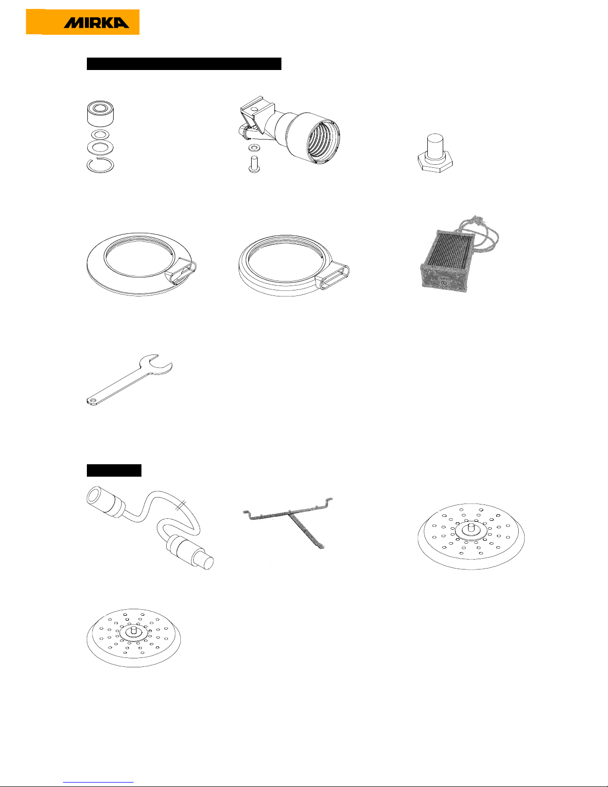
Sander Spare Parts Kits and Accessories
A Spindle Bearing Kit B 28 mm CV Swivel Fitting Kit Spindle
Code: 8993019711 Code: Code: MIN6519011 Code: 8993011611
Shroud 150mm Shroud 125mm DC Power
Code: MIN6511911 Code: MIN6515911 Code: MIN6522511
24 mm Pad Wrench
Code: 8993008011
Accessories
DC Extension cord 10m Brackets kit for Mirka 412/415 or 912/915 Net sanding PAD 150mm
Code: MIN6512211 Code: MIN6519111 Code: 8295692111
Net sanding PAD 125mm
Code: 8295592111
Page 5
5
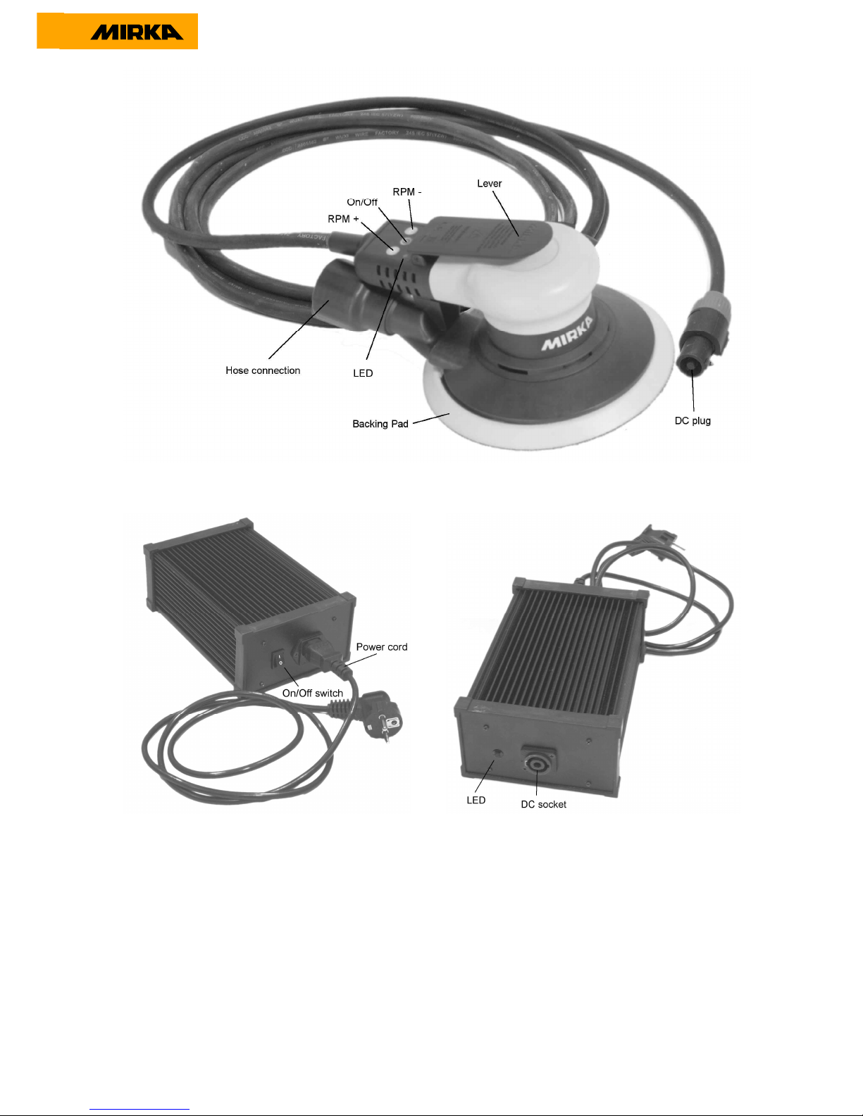
Figure 1. Sander
Figure 2. Power supply unit
Page 6

6
Index
Instructions Page
Changing pad. A1 - A3 7
Changing spindle bearing B1 - B11 8 - 10
Changing shroud / swivel exhaust assembly C1 - C6 12 - 13
Changing the fuse on the power supply and
Troubleshooting guide. 14
Page 7

7
A. Changing pad
A1.Hold the sander and the pad with one hand and use the pad wrench to unscrew the pad.
A2. Mount the new pad by hand and ensure that the threads are in the right position.
A3.Finaly tighten the pad with the pad wrench.
Page 8

8
A. Changing spindle bearing
B1.Unsrecw the pad and use a small screwdriver to remove the retaining ring that locks the
bearing in the balancer.
B2.Lift the spindle bearing out of the balancer.
B3.Notice the thin spacer in the bottom off the balancer
.
Page 9
9
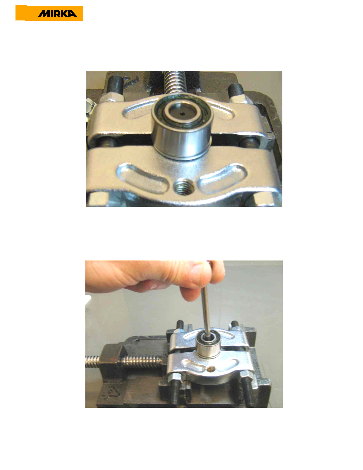
B4.Place the spindle and bearing in a bearing separator tool
.
B5.Press or gently nock the spindle out off the bearing
.
Page 10
10
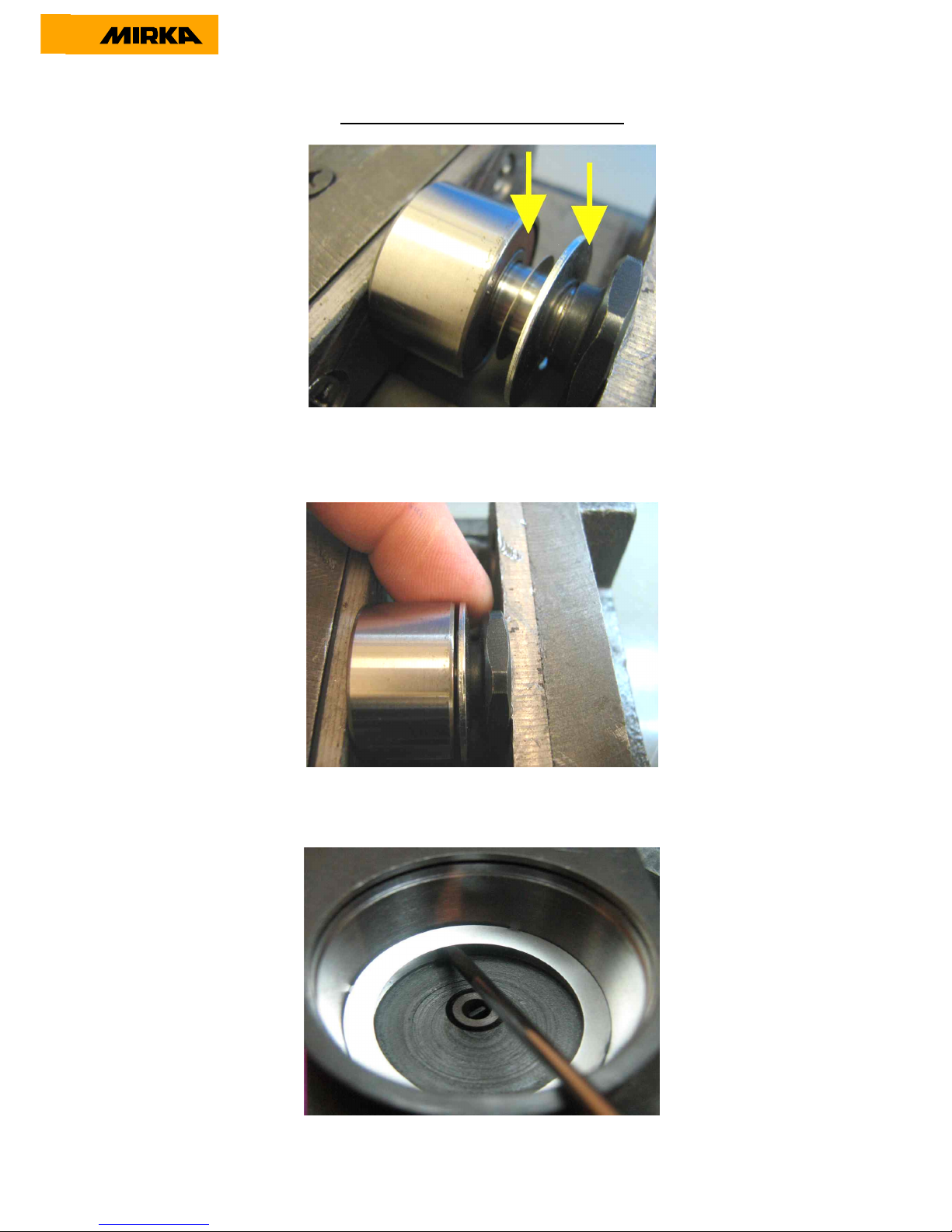
Reassembling the spindle and bearing
B6.Using a wrench, press the bearing on the spindle.
NB: Dust seal on bearing, and the curved side of the washer towards the spindle.
B7.Center the curved washer before the bearing reaches the end position on the spindle.
B8.Place the new spacer in the balancer .NB: use only one spacer.
Page 11

11
B9.Place the assembled spindle bearing in the balancer
B10.Lock the bearing in place with the retaining ring.
B11. Mount the pad and tighten it with the pad wrench.
Page 12

12
C .Changing shroud / swivel exhaust assembly.
C1.Hold the sander and the pad with one hand, use the pad wrench to unscrew the pad.
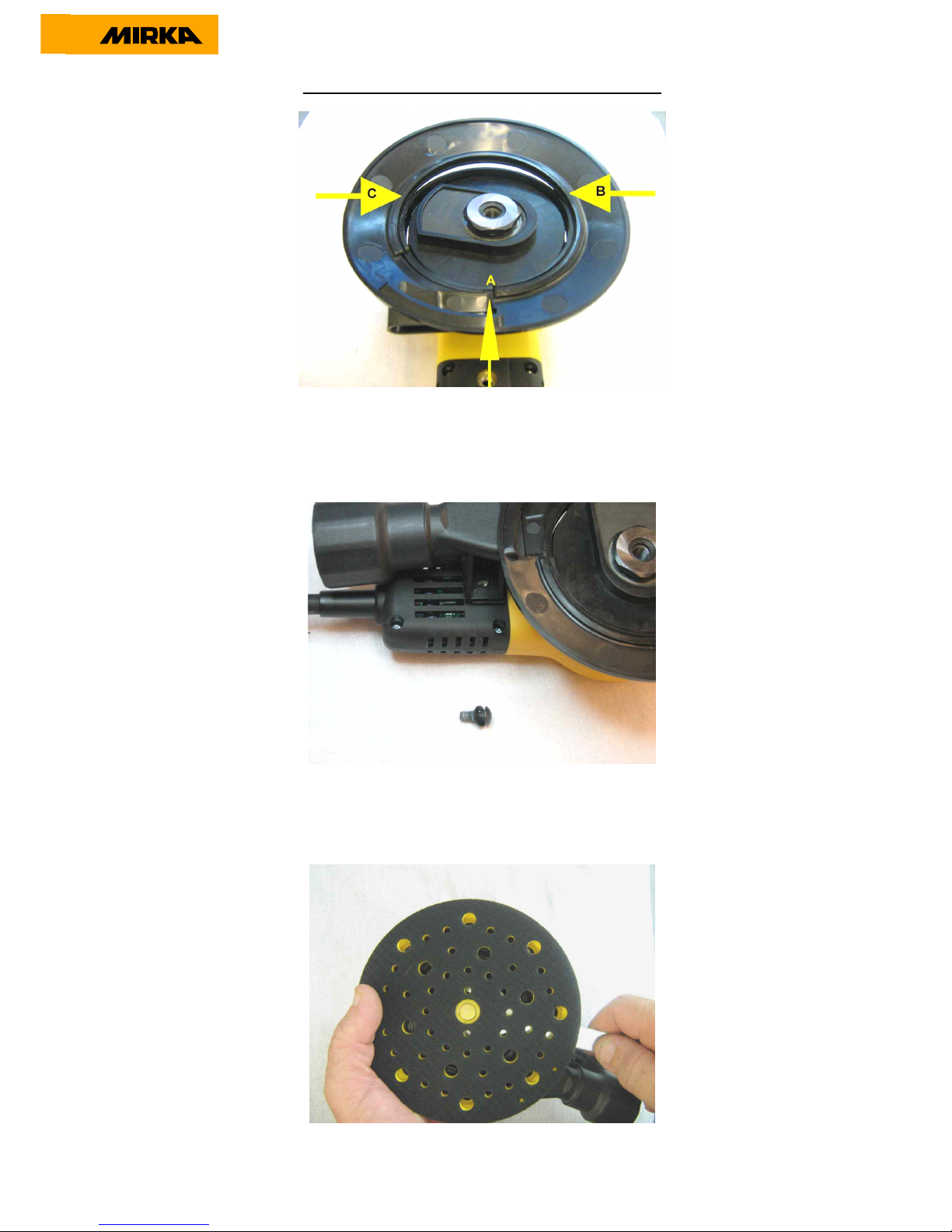
C2.Unscrew the hex screw on the swivel exhaust assembly.
C3.Remove the swivel exhaust assembly, grip the shroud and pull it of the housing.
Page 13
13
Reassembling shroud / swivel exhaust assembly.
C4 .Place the shroud on the housing, ensure that the notch on the shroud fits in the notch in the
housing point A. Start to press down the shroud at points B and C and continue to press moving
towards the front of the shroud until the shroud is in place.
.
C5. Place the swivel exhaust assembly in position and tighten the hex screw to torque 4,0Nm.
C6. Mount the pad and tighten it with the pad wrench.
Page 14
14
Changing the fuse on the power supply.
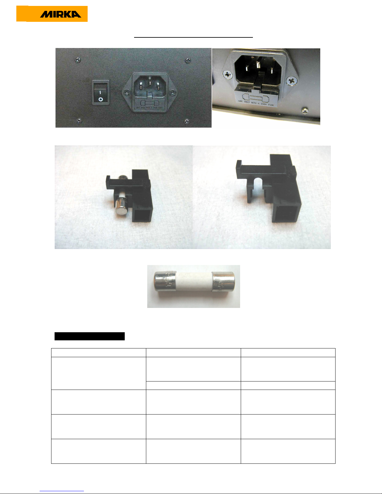
To access the fuse, unplug the mains cable. Pull out the fuse holder.
Fuse holder and the fuse. Remove the blown fuse.
Place a new fuse in the holder and reinstall the holder in the mains socket on the power supply.
Always use a fuse with the correct ratings 250V / 6,3A.
Troubleshooting Guide
Symptom Possible Cause Solution
Power cord not properly
attached to power supply unit
or to the mains socket.
Connect it properly. No light from power supply
LED when switched on.
Broken fuse. Please replace the fuse.
The LED on both power
supply and sander is changing
to red when sanding.
Too heavy long term load. Use lighter load.
Switch off the power. Wait 5
seconds. Switch on again.
The sander LED is red and the
sander is slowing down to
4000 RPM when sanding.
Temperature too high in the
sander. Too heavy long term
load.
Have lighter load to the sander
for some time and the sander
will speed up again.
The sander LED is red and
RPM is slightly reduced.
Too heavy short term load Use lighter load and the LED
will automatically change to
green
 Loading...