

Page 1

Radiation Safety. Amplified
.
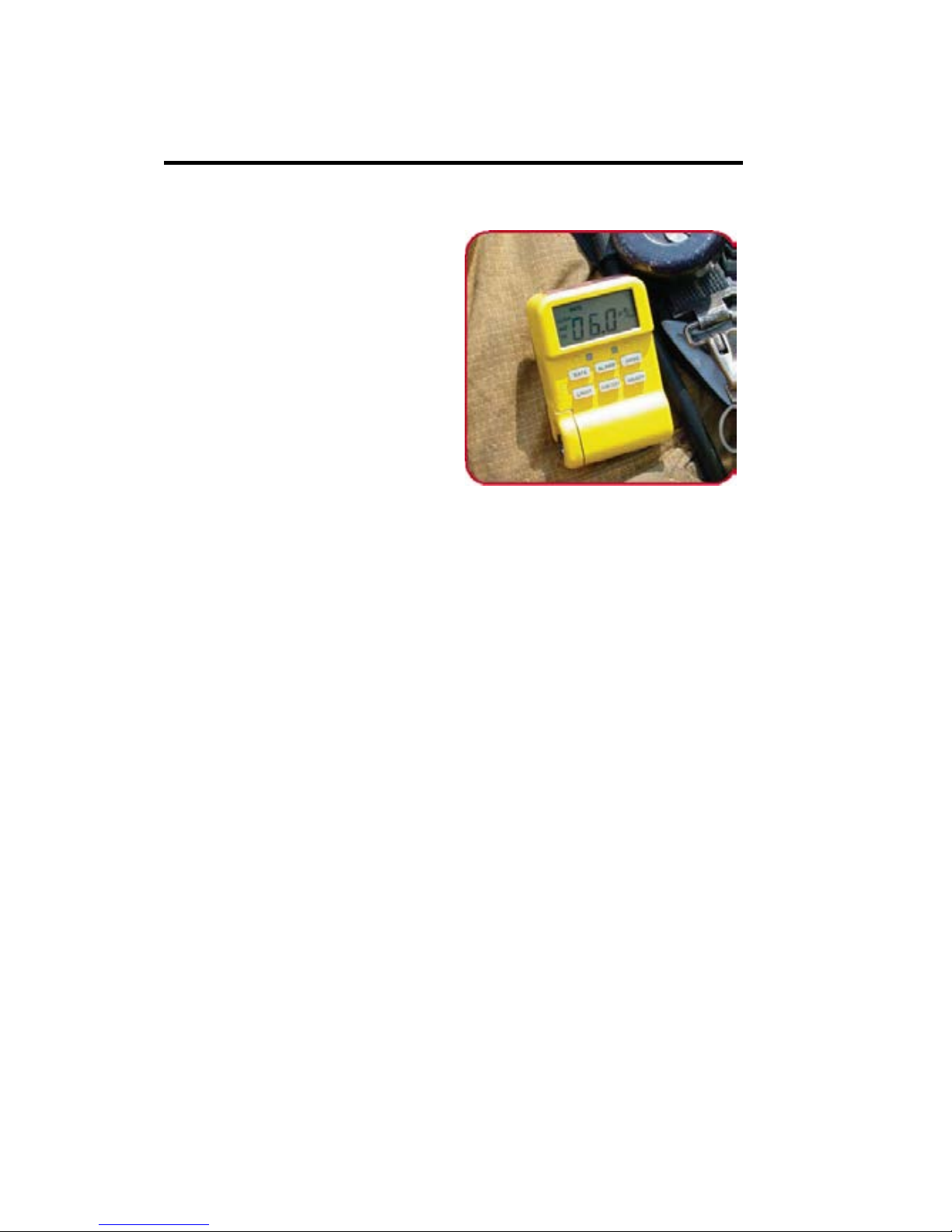
UltraRadiac™-Plus
Personal Radiation
Monitor
7068914D User’s Manual
Page 2

UltraRadiac™-Plus
Personal Radiation
Monitor
7068914D User's Manual
Page 3

Body: 7068916D
Copyright 201 7, Mirion Techn olo gi es ( Canb er ra), Inc.
The material in this document, including all information,
pictures, graphics and text, is the property of Mirion
Technologies (Canberra), Inc. and is protected by U.S.
copyright laws and international copyright conventions.
Mirion Technologies (Canberra) expressly grants the
purchaser o f this prod uct the right t o copy an y material in thi s
document for the p urchaser’s own use, including as pa rt of a
submission to regulatory or legal authorities pursuant to the
purchaser’s legitimate business needs.
No material in this document may be copied by any third
party, or used for any commercial purpose or for any use
other than that granted to the purchaser without the written
permissi on of Miri on Technolo gies (Ca nbe rr a), Inc.
Mirion Technologies (C anberra), Inc, 107 Unio n Valley Road, Oak
Ridge, TN 37830 Tel: 865-220-6300 FAX: 865-483-0406
http://www.canberra.com/
.
The information in this document describes the product as
accurately as possible, but is subject to change without
notice.
Printed in the United States of America.
UltraRadiac is a trademark of Mirion Technologies, Inc. and/or its
affiliates in the United States and/or other countries.
2
Page 4

Table of Conte nt s
Preface ............................................................ v
1. Introduction .............................................. 1
2. Controls and Indicators ........................... 5
The Function Keys ............................................. 5
The Battery Life Indicator .................................. 7
3. Basic Operation ........................................ 9
Powering the Unit .............................................. 9
Turning Off an Alarm ...................................... 10
Checking Yo ur Stay Times .............................. 12
Checking the Accumulated Dose ..................... 12
Clearing the Accumulated D ose ....................... 13
Reading the Alarm Threshold .......................... 13
Changing the Alarm Indicators ........................ 14
Using the Backlight .......................................... 15
4. Operational Verification Tests................16
Turning the Unit On ......................................... 17
Turning the Unit Off ........................................ 19
Instrument Test ................................................ 20
Display Test Sequence ................................ 20
Ending the Display Test ................................... 23
Backlight Test .................................................. 24
Sleep Mod e Test ............................................... 24
i
Page 5

Completing the Test ......................................... 25
GM Tube Failure Indication ............................. 26
Operatio n at Low Temperatures ....................... 26
Error Displays .................................................. 27
5. Setting Up the Unit ..................................28
The Rate Mode ................................................. 29
The Rate Alar m........................................... 29
Reading the Rate Alarm Threshold ............. 31
Changin g t he Rate Alarm Indicators ........... 31
Changing the Rate Alarm Thresholds ......... 32
The Dose Mode ................................................ 35
The Dose Alarms ........................................ 36
Reading the Dose Alarm Threshold ............ 37
Changing the Dose Alarm Indicators .......... 38
Changing the Dose Alarm Thresholds ........ 39
The Source Finder Mode .................................. 41
Enabling the Source Finder Mode .............. 41
Exiting the Source Finder Mode ................. 42
The Sleep Mode ............................................... 42
Enabling the Sleep Mode ............................ 43
When the Unit Wakes Up ........................... 43
Exiting the Sleep Mode ............................... 44
The Data Logging Mode .................................. 44
Capturin g Data Pairs ................................... 45
ii
Page 6

Viewing th e D ata Log ................................. 45
Clearing the Data Log ................................. 47
6. Maintenance.............................................48
Cleaning the Unit ............................................. 48
The Batteries .................................................... 49
Installing or Replacing the Batteries ........... 49
Charging the Batteries ................................ 51
The Battery Compartment ................................ 53
Latching the Compartment Door ................ 54
Attaching the Belt Clip..................................... 55
The Carrying Case ........................................... 55
A. Specifications ..........................................58
Features ............................................................ 58
Detector ............................................................ 59
Display ............................................................. 60
Alarms .............................................................. 60
Power ............................................................... 61
Environmental .................................................. 61
Physical ............................................................ 63
Qualification Testing ........................................ 63
Ordering Information ....................................... 63
iii
Page 7

B. Default Alarm Settings ............................65
C. Display Units............................................66
D. Glossary ...................................................68
E. Disposing of This Equipment .................70
iv
Page 8
Preface
The UltraRadiacPlus is a handheld pers ona l
radiation monitor
designed for the
needs of first
responders.
• Measures and displays radiation dose
rate and tot al dose
• Presett able two level au dio, visual an d
vibrating alarms for rate and dose.
• Designed to operate in ext remes of
temperature, shock, humidity, dust,
immersion and radiati on
• Large, easy-to-read backlit LCD display
• Intuitive six button user interface
• Operable/ r eadable by personnel in fire
fighting or HAZMAT protective gear
• Can be powered by NiMH rechargeable
batteries ( optional DC charger)
v
Page 9

• Ultra-small size (12.8 in.3) and weight
(9.5 oz)
• Low life cycle costs due to calibration
stability and automatic self calibration
• Mirion Technologies’s unique time-to-
count technology for wider dynamic
range
• Data logging capability to 999 points
• “Stay time” di splay shows ti me
remaining to dose alarm
• Source finder mode
• Derived from military qualified
MRAD115 R adiac Set
vi
Page 10
1. Introduction
The UltraRadiac-Plu s is a du r abl e, portable,
personal radiation monitor. Once set up, it is
preconfigured to detect certain types of
radiation, and then alert you using an audible
and/or vibrating alarm and a visual data
display. It can log (save a reco r d of) radiation
data for further evaluation by your
Administrator.
READ
THIS
If you don’t read anything else
in this manual, read the
chapters
Controls and
Indicators on pag e 5 and Basic
Operations on page 9
. These
cover the basics of using the
UltraRadiac-
Plus Personal
Radiation Monitor.
Note: Operational pro cedures are the
responsibility of the UltraRadiacPlus’s users. Instructions provided in
this manual are “how to’s”, not
procedural recommendations.
1
Page 11

Chapter 1 Introduction
Your UltraRadiac-Plu s can measure and
display both the instantaneous radiation dose
rate (Rate), t he amount of radiation bein g
measured at t his moment, and the total
accumulated radiation dose receiv ed (Dose)
since the dose memory was last cleared.
The Alarms
The UltraRadiac-Plus’s presettable alarms for
both instantaneous R ate and cumul ative Dose
can alert you to hazardous conditions. When
an enabl ed alarm’s threshold is exceeded, a
visual indicator will begin flashing and,
optionally, an LED will blink and/or an
audible alarm will sound. All units also
include a vibrator alar m th at can be
independently set.
The Radiation Units
Depending on the model, your UltraRadiacPlus is factory-set to display the Rate and the
Dose in one of these units of radiation
measurement:
• R (roentgen) – a measure of radiation
exposure.
• Sv (sievert) – a measure of absor bed
dose equival ent.
2
Page 12

Most illustrations in this manual show the
radiation units as µR (microroentgens, one
millionth of a roentgen). The units are defined
in the appendix Default Alarm Settings on
page 65.
Equipment Check
If your organization’s procedures require
periodic equipment checks, refer to the
chapter Operational Verification Tests on
page 16.
Setting Up the Unit
The UltraRadiac-Plu s has five modes: R ate,
Dose, Source Finder, Sleep, and Data
Logging. The chapter Setting Up the Unit on
page 28, describ es them and tells you how to
set and en able the Rate alar ms and the Dos e
alarms.
Maintenance Procedures
The chapter Maintenance on page 48, lists the
UltraRadiac-Plus's pr eventive maintenance
checks and describes how to install, charge, or
replace th e batteries. Th e U ltraRadiac-Plus
uses four AAA batteries and can accept either
alkaline or rechargeable Ni MH .
3
Page 13

Chapter 1 Introduction
Note: The battery recharging d evi ce should
only be used with NiMH batteries.
Connecting the charger with Alkaline
batteries may result in severe damage
to the batteries or the device.
4
Page 14
The Function Keys
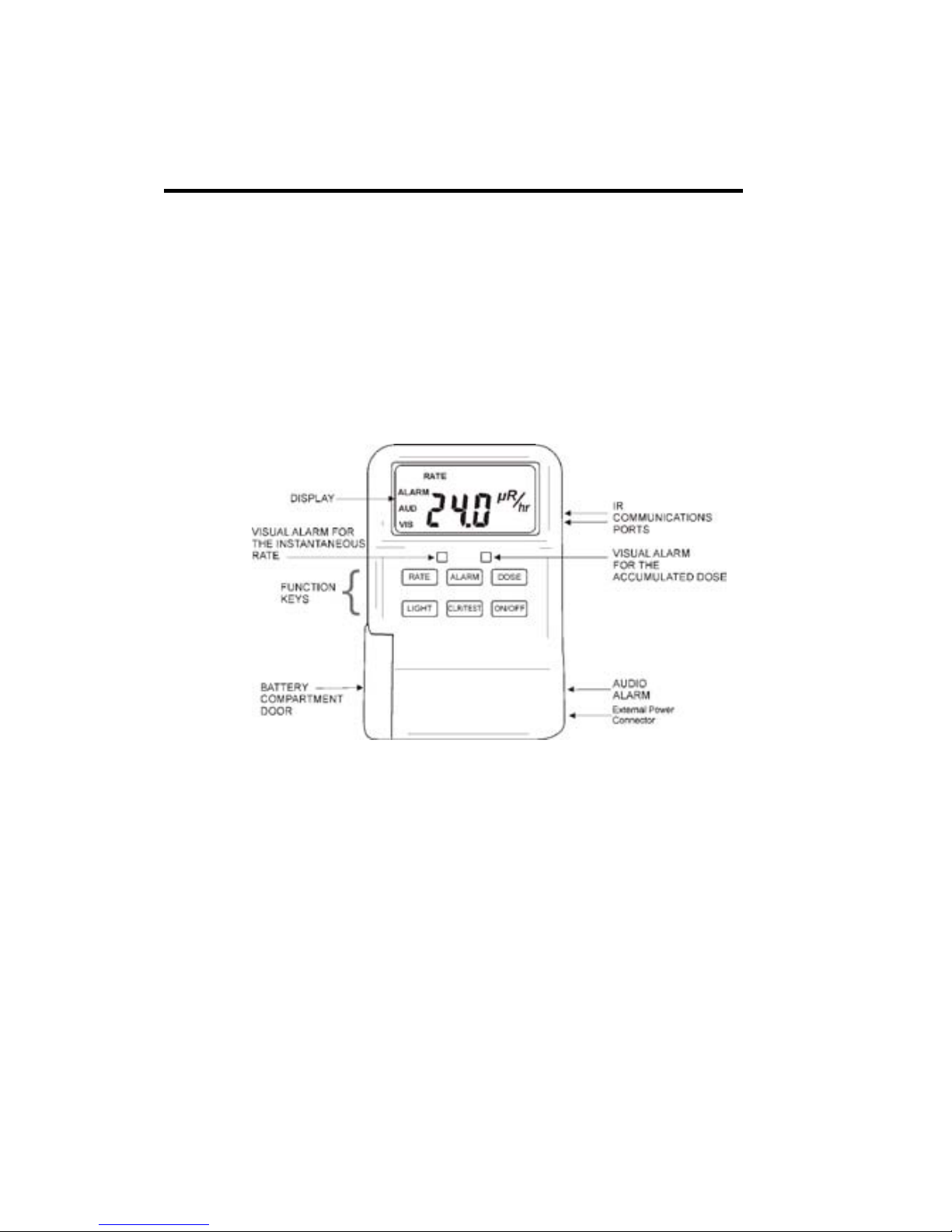
2. Controls and Indicators
This is a brief overview of the UltraRadiacPlus’s controls and indicators and its
protective case. Each of the controls and
indicators is covered in detail in the remaining
sections of the manual.
Figure 1 The UltraRadiac-Plus Front Panel
The Function Keys
The primary function of each of the function
keys is briefly described below. The
programming functions of these keys are
covered in the chapter Setting Up the Unit on
page 28.
5
Page 15

Chapter 2 Controls and Indicators
ON/OFF
Press and hold to turn the unit
on or off .
RATE
Press to change to the Rate
Mode.
DOSE
Press to change to the Dose
Mode.
ALARM
Press to see t he Stay Time,
the number of minutes you
can safely sta y in the area at
the current Dose Rate.
Specific information on Stay
Time is given in the Glossary
on page 68.
WARNING:
If the Dose Rate goes up,
your remaining Stay Time
will go down.
You should check your Stay
Time frequently when you
a
re in the presence of
radiation.
6
Page 16

The Battery Life Indicator
LIGHT
In the dark, press to
illuminate the display for
about five seconds. Note
that the backlight may not
be visible in daylight or
normal room lighting.
CLR/TEST
In the Rate Mode, press
and hold to enable the
Display Test Sequence
The Battery Life Indicator
The UltraRadiac-Plus has two battery life
indicat ors. See The Batteries on page 49 for
instruct ions on chang i ng the ba t teries .
• If a blinking 8 is displayed, the unit has
stopped functioning. Replace the
batteries before the unit’s next use.
• If a blinking BAT is seen in the top-left
corner of the display, the unit’s batteries
have 10 hours or less of useful life.
Replace the batteries as soon as
possible.
• If the display is blank, the batteries are
dead. Replace the batter ies before th e
unit’s next use.
7
Page 17

Chapter 2 Controls and Indicators
Remaining Battery Life
In the Rate Mode with the BAT indicator
blinking , pr e s s the CLR/TEST key. A t hreedigit number indicating the approximate
remaining battery life, in minutes, will be
displayed.
8
Page 18

Powering the Unit
3. Basic Operation
The first time you take your Ul traRadiac-Plus
out of its shipping carton, you’ll have to
install its batteries. For detailed instruction see
The Batteries on page 49.
Powering the Unit
To turn the unit on, press ON/OFF
until 000 is displayed.
Release ON/OFF.
In a few seconds, the instantaneous
rate will be displayed, with the word
RATE at the top left o f the screen.
If a 8 or a blinking BAT indicator
appears in the display or if the
display is blank, refer to The Battery
Life Indicators on page 7.
To turn the unit off, press ON/OFF
until – – – is displayed.
9
Page 19

Chapter 3 Basic Operation
Turning Off an Alarm
The UltraRadiac-Plu s has two alarms, Low
Level and High Level for each of two modes,
Rate and Dose.
If any alarm sounds, the next four sections tell
you how you turn it off.
• Clearing the Low Rate Alarm
Press the CLR/TEST key to turn off
the vibrator and the audio alert.
The visual alerts will continue until
the rate falls below the Low Rate
Alarm threshold.
• Clearing the High Rate Alarm
Press the CLR/TEST key to turn off
the vibrator.
The audio (if enabled) and visual
alerts will continue until the Rate
falls below th e High Rate Alarm
threshold.
10
Page 20

Checking Your Stay Times
At that time, the unit may pass into
the Low Rate Alarm region
depending on the set point. See above
instructions for clearing this alarm.
• Clearing the Low Dose A larm
Press the CLR/TEST key to turn off
the vibrator and the audio alert.
The visual alerts will continue until
the int egrated Dose is reset to 0.
To turn off the visual alerts, you’ll
have to clear t he dose memory. See
Clearing the Accumulated Dose on
page 13.
• Clearing the High Dose Alarm
Press the CLR/TEST key to turn off
the vibrator.
The visual alerts will continue until
the int egrated Dose is reset to 0.
To turn off the alerts, you’ll have to
clear the dose memory. See Clearing
the Accumulated Dose on page 13.
11
Page 21
Chapter 3 Basic Operation
Checking Your Stay Times
Press ALARM to see the number of minutes
you can safely stay in the area at the current
Dose Rate. Specific information on Stay Time
is given in the Glossary on page 68.
WARNING:
If the Dose Rate goes up,
your remaining Stay Time
will go down.
You should check your Stay
Time frequently when you
are in the presence of
radiation.
Checking the Accumulated Dose
Press DOSE t o see the accumulated
dose (the word DOSE is at at the top
right of the screen).
To return to the Rate Mode, press the
RATE key.
12
Page 22

Clearing the Accumulated Dose
Clearing the Accumulated Dose
Pres s a nd hold DOSE + CLR/TEST.
The display will flash for a few
seconds, then clear the accumulated
dose.
To return to the Rate Mode, press the
RATE key.
Reading the Alarm Threshold
Press ALARM + RATE or ALARM
+ DOSE.
You’ll s ee an H, for High Level
Alarm, displayed.
To read the Lo w Level Alarm setting,
press the RATE (DOSE) key a gain;
the display will show an L.
Press the CLR/TEST key; the
flashing display will show the
selected (H or L) alarm threshold
setting.
13
Page 23

Chapter 3 Basic Operation
If the Vibrator Alarm has b een
activated, the display will alternate
between the t hreshold value and a
vertically scrolling horizontal bar
(– – –).
Changing the Alarm Indicators
Press the ALARM + RATE keys or
the ALARM + DOSE keys.
You’ll s ee an H, for High Level
Alarm, displayed.
To change the Low Level indicators,
press the RATE (DOSE) key again;
the display will show an L.
Press the CLR/TEST key to access
the selected (H or L) indi cators.
Repeatedly pres s the ALARM key
until you see the desired combination
of indicators: AUDio, VISual,
vibrator, or no indicators.
14
Page 24

Using the Backlight
Using the Backlight
In dim light, you can enable the unit’s
backlight t o read the display.
• Press the LIGHT key.
• The display’s backlight will turn on.
• To conserve b attery power, t he
backlight will automatically turn off in
about five seconds.
15
Page 25

Chapter 4 Operational Verificati on Tests
4. Operationa l Verificat ion
Tests
These Operational Verification Tests should
be performed periodically, as required by your
departmental procedures.
Installing the Batteries
The first time you take your Ul traRadiac-Plus
out of its shipping carton, you’ll have to
install its batteries. See The Batteries on page
49 for instructions.
CAUTION:
Use of non-rechargeable
batteries or rechar geab le
batteries other than those
supplied or recommended by
Mirion Technologies
(Canberra) may cause an
explosion or other fire hazard
resulting in personal injury.
Mirion Technologies
(Canberra) is not liable for
personal injury or damage
resulting from the use of
incompatible batteries.
16
Page 26

Turning the Unit On
Turning the Unit On
Pres s a nd hold the ON/OFF key until the
display appears, then release the key.
• The unit will display the numbers 0, 1,
2, 3, 4, in sequence.
• The Rate Mode display should appear,
with the word RATE shown at the top
left of the screen ( Figure 2).
Figure 2 The Rate Display
• If 8 or a blinking BAT indicato r appear
in the display or if the display is blank,
refer to The Battery Life Indicators on
page 7.
17
Page 27

Chapter 4 Operational Verificati on Tests
• AUD and VIS indicate that the Audio
and Visual alarms are both enabled.
• The unit will start counting and
displaying the instantaneous Rate.
Naturally occurring background
radiation will cause the unit to display a
low reading
1
.
• To switch to the Dose Mode, press the
DOSE key.
• Press the RATE key to return to the
Rate Mod e.
• The rate units indicator
hr
Rµ
will
blink slowly to show that the Rate
Mode is active.
Note: Because the UltraRadiac automatically
adjusts its display to accommodate the
amount of data, the units (R, for
instance) may be displayed with a
prefix. For instance, at natural
background levels, you’ll s ee µR,
microroentgens.
1
Naturally occurring background radiation typically
measures less than 20 mR/h or 0.20 mSv/h.
18
Page 28

Turning the Unit Off
At higher exposure rates, the display
will change to mR (milliroentgens).
With large exposure rates, it will show
just R. It’s important to understand
these units because each one is 1000
times greater th an the pr evi ous one.
Turning the Unit Off
To turn the unit off:
• Pres s a nd hold the ON/OFF key.
• OFF will be displayed.
• Then you’ll see – – –.
• Release the ON/OFF key; the unit will
turn its power off.
All data collected up to this time will be
stored in memory.
19
Page 29

Chapter 4 Operational Verificati on Tests
Instrument Test
While in the Rate Mode, press and hold the
CLR/TEST key until you see the test display
in Figure 3, then rel eas e the key
2
.
Figure 3 The Test Display
Display Test Sequence
• A set of numbers in the following order
will appear. C heck that all of the
numbers are exactly as shown below.
2
The 'GN' located in the upper right corner of the
display is used only by maintenance technicians.
It's shown here so you can verify that the entire
display is operating properly.
20
Page 30

Instrument Test
00.0 µR
1 1 1 µR
2.22 mR
33.3 mR
444 mR
5.55 R
66.6 R
777 R
888 R
999 R
00.0 µR
9 (blinking)
• The blinking 9 indicates that the unit
passed all tests. A blinking 0 indicates a
failure; contact your local Mirion
Technologies (Canberra) Service Center.
• Press the CLR/TEST key to return to
Rate Mode (or wait about 10 seconds).
21
Page 31

Chapter 4 Operational Verificati on Tests
Checking the Alarm
At any time dur ing the Clr/Test sequence of
numbers:
• Press the RATE key – the audio alarm
should sound and the Rate LED, the left
and one below the display, should turn
on.
• Press the DOSE key – the audio alarm
should sound and the Dose LED, the
right hand one below the display,
should turn on.
• Press the ALARM key – the audio
alarm should sound and both LEDs
should turn on.
• If the optional vibrator alarm is
installed, the unit will vibrate when any
of these three keys is pressed.
Checking the Function Keys
When the 000 display appears during the
“Testing the Display” sequ ence, press each
function key in turn, except the ON/OFF key.
22
Page 32

Ending the Display Test
The unit will beep and display the indications
shown in the following table. Any other
numerical indication indicates a fault in that
key’s circuit.
Function Indication
DOSE
002
ALARM
010
RATE
001
LIGHT
020
CLR/TEST
004
Ending the Display Test
At the end of the test sequence, the blinking 9
will appear, indicating that the Rate Mode is
operational. A blinking 0 indicates a failure;
contact you r local Mirion Technologies
(Canberra) Service C enter.
The unit will return to the Rate Mode in about
ten seconds.
23
Page 33

Chapter 4 Operational Verificati on Tests
Backlight Test
Press the LIGHT key; the display’s backlight
will turn on for about five seconds. This
function is meant to be used in total darkness;
the backlight may not be visible in daylight or
normal room lighting.
Sleep Mode Test
Pres s a nd hold the RATE key, then press the
ON/OFF key.
• The characters SLP will be displayed
briefly.
• When you see – – – , release both keys.
• You’ll s ee th e SLEEP indicato r at t he
top of the screen (Figure 4)
24
Page 34

Completing the Test
Figure 4 The Unit is Asleep
• To wake the unit, press and hold the
ON/OFF key until the SLEEP indicator
disappears.
• The unit will cycle through the 0–4
startup s equence, th en return to the Rate
Mode.
Completing the Test
When the Ul traRadiac h as passed all tests , the
unit is ready for operation.
If the unit fails any of these Operational
Verification Tests, contact your local Mirion
Technologies (Canberra) Service Center.
25
Page 35

Chapter 4 Operational Verificati on Tests
GM Tube Failure Indication
If the unit’s Geiger-Mueller tube should stop
counting, the display will flash, showing three
rows of three d as hed lin es each (Figure 5).
Figure 5 The GM Tube Has Failed
Contact your local Mirion Technologies
(Canberra) Service Center for repairs .
Operation at Low Temperatures
At temperatures below –22 °F (–30 °C), it
takes somewhat longer for characters to form
on the display. The UltraRadiac-Plus
automatically corrects for this b y sensi ng the
ambient temperature and increasing the
display refresh time from two to five seconds.
Operatio n of the UltraRadiac-Plus is
otherwise unchanged.
26
Page 36

Error Displays
Error Displays
Above 200 R/hr (2.0 Sv/h), and up to 600 R/h
(6.0 Sv/h), the upper three -segment bar (– – –)
on the display will begin flashing to indicate
that:
• The dose rate exceeds the ran ge of the
UltraRadiac-Plus.
• The error migh t be greater than 20%.
• The value of the displayed d ose rate
(and consequently of the calculated
dose) is not accurate.
• The “true rate” might be significantly
higher than the displayed value.
Above 600 R/h (6.0 Sv/h) the unit will not
increase dose-rate measurement and will keep
displaying 600 R/h (6.0 Sv/h).
27
Page 37

Chapter 5 Setting Up the Unit
5. Setting Up t he Unit
This chapter has been written for the System
Administrator, the person responsible for your
organizati on’s Ult r aRadiac-Plus units . It
describes each of the unit’s functions and
gives detailed instructions on how to set and
enable the alarms. This is ap plicabl e only if
the functions were not disabled by the
optional Mo del S900 UltraRadiac Setup
Software.
CAUTION:
To make your changes
permanent, you must go
through the entire setup
sequence outlined in this
chapter.
Exiting the sequence before it
is complete, such as by
changing only one parameter
then waiting 10 seconds for
the display to return to the
Rate Mode, will cause all
changes to be lost when the
unit is turned off.
28
Page 38

The Rate Mode
The Rate Mode
To turn the UltraRadiac-Plus on, press and
hold ON/OFF key until you see t he Rate
display in Figure 6.
Figure 6 The Rate Display
The Rate Alarm
There are two Rat e Alarm Thresholds: Low
Rate, for a min or hazard, and High Rate, for a
severe hazard.
The alarm indicators will remain enab led as
long as you remain in the radiation area that
triggered the alarm.
29
Page 39

Chapter 5 Setting Up the Unit
High Threshold
There are several i ndicators for the High Rate
Alarm Threshold (Figure 6).
• Visual Enabled – The entire display
and the left LED will flash quickly.
• Audio Enabled – The audio will beep
quickly.
• Optio nal Vi brator Enabled – The unit
will vibrate.
Low Threshold
There are several i ndicators for the Low Rate
Alarm Threshold (Figure 6).
• Visual Enabled – The RATE and
ALARM indicato r s and the left LED
will flash slowly.
• Audio En abled – The audio will beep
slowly.
• Optio nal Vi brator Enabled – The unit
will vibrate.
The optional Vibrator Alarm can be used in
addition to the audio and visual alarms when
background noise makes the audio alarm hard
to hear.
30
Page 40

The Rate Mode
Reading the Rate Alarm Threshold
To display the High level (H) or Low level (L)
rate alarm thr es holds:
• Press the ALARM and RATE keys.
• You’ll s ee an H, for High Level Al arm,
displayed.
• To read the Lo w Level Alarm setting,
press the RATE key again; the display
will show an L.
• Press the CLR/TEST key; the flashing
display will show the selected (H or L)
alarm threshold setting.
• If the optional Vibrator Alarm has been
activated, the display will alternate
between the threshold value and a
vertically scrolling horizontal bar
(– – –).
Changing the Rate Alarm Indicators
To change th e H igh level (H) o r Low level (L)
alarm indicator settings:
• Press the ALARM and RATE keys.
• You’ll s ee an H, for High Level Al arm,
displayed.
31
Page 41

Chapter 5 Setting Up the Unit
• To change the Low Level indicators,
press the RATE key again; the display
will show an L.
• Press the CLR/TEST key to access the
selected (H or L) indicators.
• Repeatedly pres s the ALARM key until
you see the desired combination of
indicators, AUDio, VISual, vibrator (–
– –), or no indicators.
• The unit will automatically return to the
Rate Mode display about 10 seconds
after the last keypress.
Changing the Rate Alarm Thresholds
To change th e H igh level (H) o r Low level (L)
rate alarm setti ngs:
• Press the ALARM and RATE keys.
• You’ll s ee an H, for High Level Al arm,
displayed.
• To access the Low Level Alarm
settings, press th e RATE key again; the
display will show an L.
• Press the CLR/TEST key; the flashing
display will show the selected alarm
level (H or L) settings.
32
Page 42

The Rate Mode
• If the optional Vibrator Alarm has been
activated, t he display will alternate
between the threshold value and a
vertically scrolling horizontal bar
(– – –).
Changing the Alarm Indicators
• To choose one or more of the alarm
indicat ors for the selected alarm level:
• Repeatedly pres s the ALARM key until
you see the desired combination of
indicators, AUDio, VISual, vibrator, or
no indicators.
Setting the Alarm Threshold
To set the threshold for the selected alarm
level (Figure 7):
Figure 7 Changing the Rate Alarm Threshold
33
Page 43

Chapter 5 Setting Up the Unit
• Press the CLR/TEST key; the decimal
point and the threshold unit indicator
will begin to flash.
• Repeatedly pres s the RATE key until
the desired decimal point location and
threshold unit indication are displayed.
• Press the CLR/TEST key. This action
will lock in the selected decimal point
location and threshold unit indication.
• The left-most digit will begin to flash.
• Repeatedly pres s the RATE key until
the desired value of the digit is
displayed.
• Press the CLR/TEST key to lock in the
digit’s value. The next digit will begin
to flash.
• Repeat the above two steps to select and
lock in each of the two remaining
digits.
• When the las t digit has b een set , the
entire threshold value and unit will
flash.
• Press the CLR/TEST key to return to
the Rate Mode or wait about 10
seconds.
34
Page 44

The Dose Mode
The Dose Mode
When the unit is on, dose data is continuously
accumulated and updated every two secon ds.
• To enter the Dose Mode, pr es s the
DOSE key.
• The Dose Mode display (Figure 8) will
show you the dose that has accumulated
since the unit's memory was last reset to
zero.
Figure 8 The Dose Display
The AUD and VIS display indicators will be
seen only if the corresponding Dose Alarm
mode and its indicator have been enabl ed. See
Changi ng the Dose Alarm Indicator on page
38.
35
Page 45

Chapter 5 Setting Up the Unit
The Dose Alarms
There are two Dose Alarm threshold s : Low
Dose, for a minor hazard, and High Dose, for
a severe hazard.
The optional Vibrator Alarm can be used in
addition to the audio and visual alarms when
background noise makes the audio alarm hard
to hear.
High Threshold
There are several i ndicators for the High Dose
Alarm Threshold (Figure 8).
• Visual Enabled – The DOSE and
ALARM indicators and the right LED
will flash quickly.
• Audio Enabled – The aud io will beep
quickly.
• Optio nal Vi brator Enabled – The unit
will vibrate.
36
Page 46

The Dose Mode
Low Threshold
There are several i ndicators for the Low Dos e
Alarm Threshold (Figure 8).
• Visual Enabled – The ALARM
indicators and the right LED will flash
slowly.
• Audio Enabled – The audio will beep
slowly.
• Optio nal Vi brator Enabled – The unit
will vibrate.
Reading the Dose Alarm Threshold
To display the High level (H) or Low level (L)
dose alarm thresholds:
• Press the ALARM and DOSE keys.
• You’ll s ee an H, for High Level Al arm,
displayed.
• To read the Lo w Level Alarm setting,
press the DOSE key again; t he display
will show an L.
37
Page 47

Chapter 5 Setting Up the Unit
• Press the CLR/TEST key; the flashing
display will show the selected (H or L)
alarm threshold setting.
• If the optional Vibrator Alarm has been
activated, t he display will alternate
between the threshold value and a
vertically scrolling horizontal bar
(– – –).
Changing the Dos e Alarm Indicators
To change th e H igh level (H) o r Low level (L)
alarm indicator settings:
• Press the ALARM and DOSE keys.
• You’ll s ee an H, for High Level Al ar m,
displayed.
• To change the Low Level indicators,
press the DOSE key again; t he display
will show an L.
• Press the CLR/TEST key to access the
selected (H or L) indicators.
• Repeatedly pres s the ALARM key until
you see the desired combination of
indicators, AUDio, VISual, vibrator
(– – –), or no indicators.
38
Page 48

The Dose Mode
• The unit will automatically return to the
Dose Mode display about 10 seconds
after the last keypress.
Changing the Dos e Alarm
Thresholds
To change th e H igh level (H) o r Low level (L)
rate alarm settings:
• Press the ALARM and DOSE keys.
• You’ll s ee an H, for High Level Al arm,
displayed.
• To access the Low Level Alar m
settings, press th e DOSE key again; the
display will show an L.
• Press the CLR/TEST key; the flashing
display will show the selected alarm
level (H or L) settings.
• If the optional Vibrator Alarm has been
activated, the display will alternate
between the threshold value and a
vertically scrolling horizontal bar
(– – –).
39
Page 49

Chapter 5 Setting Up the Unit
Setting the Alarm Threshold
To set the threshold for the selected alarm
level:
• Press the CLR/TEST key; the decimal
point and the threshold unit indicator
will begin to flash.
• Repeatedly pres s the DOSE key until
the desired decimal point location and
threshold unit indication are displayed.
• Press the CLR/TEST ke y. T h is action
will lock in the selected decimal point
location and threshold unit indication.
• The left-most digit will begin to flash.
• Repeatedly pres s the DOSE key until
the desired value of the digit is
displayed.
• Press the CLR/TEST key to lock in the
digit’s value. The next digit will begin
to flash.
• Repeat the above two steps to select and
lock in each of the two remaining
digits.
• When the las t digit has b een set , the
entire threshold value and unit will
flash.
40
Page 50

The Source Finder Mode
• Press the CLR/TEST key to return to
the Rate Mode or wait about 10
seconds.
The Source Finder Mode
The Source Finder Mode allows the unit to
locate an i s olated sou r ce. In this mode, th e
unit will start clicking if the unit is near
radioactive material. As you move clos er to
the radioactivity (or further away), the unit
will click faster (or slower).
For best results, aim the top of the unit at the
suspected source of the radiation.
The Rate and Dose modes are active when t he
Source Finder Mode is enabled. This means
that you can r ead the higher Rate or Dose
without exiting the Source Finder Mode.
Enabling the Source Finder Mode
To enable the Source Finder Mode:
• Pres s a nd hold the RATE key until the
display changes to a flashing 1.
• Release the RATE key.
41
Page 51

Chapter 5 Setting Up the Unit
Exiting the Source Finder Mode
To exit the Source Finder Mode:
• Pres s a nd hold the RATE key until the
display changes to a flashing 0.
• Release the RATE key.
The Sleep Mode
When the Sleep Mode is enabled, most of the
unit’s circuits will be turned off to conserve
battery power. Every 5 minutes, the unit will
wake up for 4–6 seconds and check the
current R ate.
The battery life time for th e U ltraRadiac-Plus
in this mode is approximately 2000 hours.
WARNING:
Do not place the unit in
Sleep Mode before
responding!
Doing so can expose you to
radiation for as long as five
minutes before you are
alerted.
42
Page 52

The Sleep Mode
Enabling the Sl eep Mode
To enable the Sleep Mode:
• Pres s a nd hold the RATE key, then
press the ON/OFF key.
• The characters SLP will be displayed
briefly.
• When you see – – – , release both keys.
• You’ll s ee th e SLEEP indicator at the
top of the screen (Figure 9)
Figure 9 The Unit is Asleep
When the Unit Wakes Up
• It compares th e current Rate with the
Rate Alarm th r es holds.
• If a Rate Alarm is triggered, the unit
will s tay awake.
43
Page 53

Chapter 5 Setting Up the Unit
• If no Rate Alarm thresholds have been
exceeded, the unit will go back to sleep
for five minutes.
• This wake-sleep c ycle will repeat
continuously until the Sleep Mode is
cancelled.
Note: The unit does not accumulate Dose
data while asleep.
Exiting the Sleep Mode
To exit the Sleep Mode:
• Pres s a nd hold the ON/OFF key until
the unit starts cycling through the 0–4
startup s equence.
• The unit will then exit the Sleep mode
and ent er R ate Mode.
The Data Logging Mode
The Data Log lets you record up to 999
individual dose/rate data pairs , each wit h an
index number, for later retrieval. This is useful
for performing a survey or for cataloging
readings.
44
Page 54

The Data Logging Mode
Capturing Data Pairs
To capture data pairs, the unit must be ON
and in the Rat e Mode.
• Press the RATE and DOSE keys
together.
• Hold both buttons down until the
displayed number stops blinking (in
about three seconds),
• The next sequential rat e/dose pair in dex
number will appear.
• Release both buttons. The unit will save
the data pair and its index, then return
to the Rate M ode. This process takes
about 10 seconds.
• To record another reading, point the
unit at the location to be recorded and
repeat the process.
Viewing the Data L o g
To view the stored data, the unit must be OFF.
• Press the RATE and OFF/ON keys
together.
45
Page 55

Chapter 5 Setting Up the Unit
• When the unit turns on, the last
sequence number recorded will be
displayed.
• Press the RATE button to scroll down,
or the DOSE button to scroll up,
through the memory.
• The first number shown in the display
will be the index number, scrolling up
(DOSE button) will next display the
Rate data and scrolling up once again
will display the Dose data.
• Scrolling down (RATE bu tton) will
reverse the order of sequ ence numbers
but will still display first Rate data then
Dose data.
• Scrolling will wrap around the memory,
from first index entry to last, or last to
first.
• To return to normal operation, the unit
must be turned off and then on again
(normal turn on sequence).
46
Page 56

The Data Logging Mode
When the 999th sequence number has been
recorded , the unit will cycle back to the first
sequence number and any new data records
will overwrite the previously recorded data in
that location.
Clearing the Data Log
To clear all stored data, you must be in the
Viewing th e D ata Log mode. (See the
previous section.)
• While pressing both the RATE and
ALARM keys, press and hold the
CLR/TEST key for two seconds.
• The first index number (0) will appear
• This ind icates that al l d ata has been
cleared.
• To return to the Rate/Dose mode of
operation, turn the unit OFF, then back
ON.
47
Page 57

Chapter 6 Maintenance
6. Maintenance
Prevent ive maintenance consists of routine
checks of the eq uipment b efore and after each
mission, or as required by procedure.
Routine Checks Include:
• Cleani ng the uni t.
• Inspecti ng the battery compartment ’s
door gasket.
• Inspecti ng the battery contacts for
corrosion.
Cleaning the Unit
Remove dust, moisture and loose dirt from the
outside surfaces of the Ultr aRadiac-Plus with
a clean soft cloth. If necessary, the unit may
be cleaned with a mild solution of ordinary
detergent and water, rinsed, and thoroughly
dried.
48
Page 58

The Batteries
The Batteries
If you’re installing batteries for the first time,
the following caution can be disregarded. If
you’re replaci ng the bat teries, be sure to turn
the unit off first.
Installing o r Replacing the Batteries
• To open the battery compartment door,
turn its fastener a qu arter-turn
counterclockwise, swing the door open
and slide out all four batteries.
• Install fresh batteries in the order shown
in Figure 10.
CAUTION:
Be sure to observe the
polarity next to each of the
four battery slots. The end of
the battery facing out should
match the slot’s marked
polarity, as shown in Figure
10 and Figure 11.
• With the batteries correctly installed,
close and latch the door. See Latching
the Compartment Door on pa g e 54.
49
Page 59

Chapter 6 Maintenance
Figure 10 Location of the Batteries
Figure 11 The Battery Polarity Indicators
50
Page 60

The Batteries
Charging the Batteries
The UltraRadiac-Plus is equipped with the
capability to use rechargeable AAA batteries
as well as standard alkaline batteries. Nickel
Metal Hydride (NiMH) batteries can be
inserted in to the unit and used directly. To
recharge the NiMH batteries insert them into
the UltraRadiac-Plus and set the battery
charger switch to ON position. In this setting,
the charger will continuously charge the
batteries while they are in the unit. In the
POWER position, the UltraRadiac-Plus can be
powered directly off of the charger without
the batteries present. It can run in this mode
indefinitely, although it can not recharge
batteries in this mode. See Figure 12 and
Figure 13.
Figure 12 UltraRadiac-Plus Battery Charger
51
Page 61

Chapter 6 Maintenance
Figure 13 Right Side View of UltraRadiac-
Plus
Note: Do not attempt to charge standard
alkaline batteries. Damage can occur.
52
Page 62

The Battery Compartment
The Battery Compartment
To open the battery compartment door, turn its
latch a quarter-turn counterclockwise and
swing the door ope n.
• Inspect the four battery contacts on the
inside of the door (Figure 14). If any
corrosion is seen, cl ean it off with a
pencil eras er .
• Inspect the s eal on the inside of the
door (Figure 14); it should be whole
and ent ire. If the seal is cracked or
broken, the unit may no longer be
watertight.
• Inspect t he O-ring seal around the door
latch’s post (Figure 14). If the seal is
cracked or broken, the unit may no
longer be watertight.
• For repair, co nt act your local Mirion
Technologies (Canberra) Service
Center.
• When the inspection is complete, clo s e
and latch the door. See the following
section Latching the Com par tm e nt
Door.
53
Page 63

Chapter 6 Maintenance
Figure 14 The Inside of the Battery Door
Latching the Compartment Door
Swing the b attery cover closed, press it firmly
against th e unit and turn the fastener a quarterturn clockwise.
Note: It may be necess ary to turn the fastener
slightly to line it up with the latch post
before latch will engage.
When the door is properly closed, it will be
possible to lay the fastener’s D-ri ng down in
the cover’s fastener recess.
Note: When the door is latched, the unit may
turn itself on in the Sleep Mode. To
return to normal operation:
54
Page 64

Attaching the Belt Clip
• Press and hold the ON/ OFF key for
about 2 seconds.
− The unit will cycle through the
display startup sequence, then
enter the Rate Mode.
Attaching the Belt Clip
To attach the supplied belt clip, screw the
clip’s two captive retaining screws into the
threaded inserts at the top of the unit’s rear
panel.
Note: To prevent cross-threading damage,
insert each s cr ew loosely, then tighten
them alternately a few turns at a time.
Do not over-tighten.
The Carrying Case
If the belt clip is installed, remove it from the
back of the Ult raRadiac-Plus by unscrewing
its two captive retaining screws and lifting the
clip off the unit.
55
Page 65

Chapter 6 Maintenance
Now put the UltraRadiac-Plus into the
carrying case with the display toward the
bottom (closed) end of the case. To close the
case, refer to Figure 15 and...
Fold the top flap down over the
front of the case.
Pull the narrow strap across the top
flap.
Secure the narrow strap to both the
top flap and the side of the case.
Thread your belt through the slots in
the belt loop.
56
Page 66

The Carrying Case
Figure 15 Using the Carrying Case
57
Page 67

Appendix A Specifications
A. Specifications
Features
DOSE RATE – URAD-PLUS-S: 0.01 µSv/h
to 2 Sv/h; URAD-PLUS-R: 1.0 µR/h to 200
R/h. Meets ANSI-N42.33-2006 standard
above 1 µSv/h (100 µR/h). Dose rat e alarm
will function to 5.0Sv/h (50 0 R/h).
DOSE – URAD-PLUS-S: 0.001 µSv to 999
Sv; URAD-PLUS-R: 0.1 µR to 999 R.
PRESETTABLE AUDIBLE AN D VISUAL
ALARMS – User-defined and -set dose and
dose rate al ar ms.
INITIALIZATION TIME – Operational in
less than five seconds.
SETUP TIME – Less than one minute for all
checks and alarms.
ACCURACY – Within ±30%. fro m 1 µSv/h
(100 µR/h) to 2.0 Sv/h (200 R/h).
58
Page 68

Detector
DATA RECORDING – Local data logging to
999 data points; data downloadable via optical
(IR) communications port.
SELF MONITORING – Continual selfmonitoring for the instrument’s state of health.
CASE – Die-cast al uminum; available in
black or yellow.
EMI SUSCEPTIBILITY – Will not be
affected, or cause other equipment to be
affected, by its use.
OPERABLE AND READABLE – By persons
wearing protective clothing.
Detector
DETECTOR – Energy compensated GM
tube.
GAMMA ENERGY DEPENDENCE – ±40%,
60 keV to 1.5 MeV.
TOTAL (ACCUMULATED) DO SE
READOUT – Will not be erased when r ead;
resettable t o zero as des ired.
59
Page 69

Appendix A Specifications
RESPONSE TIME – Achieves 90% of final
reading in one second; subject to a step
change from 1mR/h (10 µSv/h) to 55mR/h
(550 µSv/h); updates display every second.
Display
LCD – Readable at 3 ft (1 m), updated every
two seconds; can be backlit for night use.
UNITS – URAD-PLUS-S provides data in
units of µSv, mSv, Sv, µSv/h, mSv/h and
Sv/h; URAD-PLUS-R provides data in units
of µR, mR, R, µR/h, mR/h and R/h.
Alarms
SELECTABLE ALARMS – Has selectable
Visual and Audible indicators for day or night
use. Alarm levels are settabl e over ent ire
dynamic range.
ALARM TYPES – Alarm on dose rate and
total cumulative dose.
ALARM LEVELS – Two alarm levels
available for each type to i ndicate minor or
severe hazard.
60
Page 70

Power
AUDIBLE ALARM – >85 dBA at 30 cm.
VIBRATION ALARM – Included.
Power
BATTERIES – Four AAA 1.5 V alkaline
batteries.
MINIMUM BATTERY LIFE – 10 hours of
battery life remaining allows display of
remaining time.
LOW BATTERY INDICATION – Triggered
when the remaining bat tery life is
approximately 10 hours; allows display of
remaining time in minutes.
Accept standard off the shel f rechargeable
NiMH batteries with DC charger to URADPLUS power connector.
Environmental
OPERATING TEMPERATURE: –22°F to
141°F (–30°C to +61°C). Vibrating and
audible alarms functional to -50°C.
61
Page 71

Appendix A Specifications
At operating temperatures below -22°F (30°C), it takes somewhat longer for characters
to form on the display. The UltraRadiac-Plus
automatically corrects for this b y sensi ng the
ambient t emperature and increasing display
refresh time from two to five second s.
Operatio n of the UltraRadiac-Plus is
otherwise unchanged. Measurement is still
accurate and audible and vibrating alar ms are
still functional even with the slower display
refresh rate at low temperatures.
STORAGE/TRANSPOR T TEMPE RATURE:
–40°F to 158°F (–40°C to +70°C).
HUMIDITY – Functions correctly over RH
40% to 93% at 95 °F (35°C).
WATER IMMERSION (including salt water)
– 3 ft (1 m) for at least 2 hr.
SAND/DUST – Operates in winds with
exposure to fine dust and sand particles.
FUNGUS – Built from fungus resistant
materials.
VIBRATION AND SHOCK – Withstands
vibration associated with transport and shocks
of dropping while in use.
62
Page 72

Physical
ALTITUDE – 40 000 ft (12 000 m).
Physical
DIMENSIONS – 3.94 x 2.62 x 1.24 in. (100 x
66 x 31 mm) (HWD).
WEIGHT – 8.8 oz (249 g) including batteries.
Pouch weight is 2.4 oz (68 g).
VOLUME – 12.8 in.
3
(210 cc).
Qualification Testing
UltraRadiac-Plus has been type-tested to meet
ANSI-N42.33-2006 with minor exceptions:
Sec. 6.4, Sec. 5.12 and S ec. 5.7 (option al).
Ordering Information
URAD-PLUS-S/Y – UltraRadiac-Plus,
Yellow, Sv unit, alkaline batteries.
URAD-PLUS-S/B – UltraRadiac-P lu s , Black,
Sv unit, alkaline batteries.
URAD-PLUS-R/Y – UltraRadiac-Plus,
Yellow, R unit, alkaline batteries.
63
Page 73

Appendix A Specifications
URAD-PLUS-R/B – UltraRadiac-Plu s , Black,
R unit, alkaline batteries.
URAD-PLUS-DCCHARG – DC ch arger with
cigarette ligh ter conn ector (needs NiMH
rechargeable batteries to operate).
URAD-PLUS-MOUNT – Vehicle mount for
URAD-PLUS (allows the use of DC charger).
64
Page 74

B. Default Alarm Settings
The Dose and Rate alarm settings (thresholds)
for the Ultr aRadiac-Plus are factory set to the
values in the following tables.
R Low Setting High Setting
Rate 500 µR/hr 2 R/hr
Dose 100 mR 10 R
Sv Low Setting High Setting
Rate 1 mSv/hr 100 mSv/hr
Dose 1 mSv 100 mSv
The factory settings can b e changed manual ly
(refer to the chapter Setting Up the Unit on
page 28), or via the optional Model S900
UltraRadiac Setup Software.
CAUTION:
The System Administrator is
responsible for determining
and setting the proper
operational alarm thresholds
for each UltraRadiac-Plus.
65
Page 75

C. Displ a y Units
Your unit’s display will show R or Sv*3. Any
unit can have larger and smaller subunits,
which are indicated by prefixes. As the Rate
and Dose change, the Ult raRadiac-P lus will
automatically adjust its displayed un its.
For example: The Rate may start with µR/h
(natural background radiation is less than 20
µR/h). If the Rate increases beyond 999 µR/h,
the display will change to mR/h.
micro (µ) µR – one millionth of a
roentgen
milli (m)
mR – one thousandth of a
roentgen (or µR times
1000)
centi (c)**
cR – one hundr e d t h of a
roentgen (or mR times
10)
the base unit
R – one roentgen
(cR times 100)
3
The display units are set at the factory; they are not
user chan geable.
66
Page 76

** The ‘centi’ prefix will be seen only on
UltraRadiac's displaying sievert units.
67
Page 77

D. Glossary
These brief exp lanations are included to
define terms used in this manual.
Dose
The total amount of radiation received. Also
called Accumul ated Dose.
Dose Rate
The average rat e ( in time) of radi ation; e.g.,
Roentgen per hour. Also called Rate.
Rate
The amount of radiation measured by the
UltraRadiac-Plus every 2 seconds, then
extrapolated to and displayed as units per
hour.
Roentgen (R)
Unit of measure of radiation exposure;
monitors the amount of radiation received.
Sievert (Sv)
Unit of measure of absorbed radiation;
monitors the biological danger of radiation.
68
Page 78

Stay Time
The Stay Time is how much ti me r emains, at
the current Dose Rate, before the High Dose
Alarm is triggered. Sta y Time is calculat ed by
dividing (the High Dose Alarm Setpoint
minus the al r eady accumulated Dose) b y the
current Dose Rate, then converting the result
to minutes. If the display reads 999, the
maximum, your Stay Time is at least 16.5
hours.
WARNING:
If the Dose Rate goes up,
your remaining Stay Time
will go down.
You should check your
Stay Time frequently when
you are in the presence of
radiation.
69
Page 79

E. Disposing of This
Equipment
Electrical and electronic equipment contain
hazardous substances that, if disposed of
improperl y, can have a negati ve effect on the
environment and on human healt h.
Users / owners of this equipment have the
responsibility to ensure that this equipment
does not pose a threat to the environment or to
humans when it becomes obsolete and
requires disposal.
The symbol below, also found on your
equipment, indicates that this equipment
should not be di sposed of in unsorted
municipal waste.
Therefore, following the provisions of
COUNCIL DIRECTIVE 2002/96/EC on
waste electrical and electronic equi pment
(WEEE), we ask that you contact your nearest
Mirion Technologies office for instructions
on the proper disposal of this equipment.
70
Page 80

Warranty
Mirion Technologies (Canberra), Inc., (we, us, our) warrants to the
customer (you, your) that for a period of ninety (90) days from the
date of shipment, software provided by us in connection with
equipment manufactured by us shall operate in accordance with
applicable specifications when used with equipment manufactured
by us and that the media on which the software is provided shall
be free from defects. We also warrant that (A) equipment
manufactured by us shall be free from defects in materials and
workmanship for a period of one (1) year from the date of
shipment of such equipment, and (B) services performed by us in
connection with such equipment, such as site supervision and
installation services relating to the equipment, shall be free from
defects for a period of one (1) year from the date of performance
of such services.
If defects in materials or workmanship are discovered within the
applicable warranty period as set forth above, we shall, at our
option and cost (A) in the case of defective software or equipment,
either repair on a return to factory basis or replace the software or
equipment, or (B) in the case of defective services, re-perform
such services.
LIMITATIONS
EXCEPT AS SET FORTH HEREIN, NO OTHER WARRANTIES
OR REMEDIES, WHETHER STATUTORY, WRITTEN, ORAL,
EXPRESSED, IMPLIED (INCLUDING WITHOUT LIMITATION,
THE WARRANTIES OF MERCHANTABILITY OR FITNESS FOR
A PARTICULAR PURPOSE) OR OTHERWISE, SHALL APPLY.
IN NO EVENT SHALL WE HAVE ANY LIABILITY FOR ANY
SPECIAL, EXEMPLARY, PUNITIVE, INDIRECT OR
CONSEQUENTIAL LOSSES OR DAMAGES OF ANY NATURE
WHATSOEVER, WHETHER AS A RESULT OF BREACH OF
CONTRACT, TORT LIABILITY (INCLUDING NEGLIGENCE),
STRICT LIABILITY OR OTHERWISE. REPAIR OR
REPLACEMENT OF THE SOFTWARE OR EQUIPMENT
DURING THE APPLICABLE WARRANTY PERIOD AT OUR
COST, OR, IN THE CASE OF DEFECTIVE SERVICES,
REPERFORMANCE AT OUR COST, IS YOUR SOLE AND
EXCLUSIVE REMEDY UNDER THIS WARRANTY.
Page 81

EXCLUSIONS
Our warranty does not cover damage to equipment which has
been altered or modified without our written permission or damage
which has been caused by abuse, misuse, accident, neglect or
unusual physical or electrical stress, as determined by our Service
Personnel.
We are under no obligation to provide warranty service if
adjustment or repair is required because of damage caused by
other than ordinary use or if the equipment is serviced or repaired,
or if an attempt is made to service or repair the equipment, by
other than our Service Personnel without our prior approval.
Our warranty does not cover detector damage due to neutrons or
heavy charged particles. Failure of beryllium, carbon composite,
or polymer windows or of windowless detectors caused by
physical or chemical damage from the environment is not covered
by warranty.
We are not responsible for damage sustained in transit. You
should examine shipments upon receipt for evidence of damage
caused in transit. If damage is found, notify us and the carrier
immediately. Keep all packages, materials and documents,
including the freight bill, invoice and packing list.
Revised 04 Nov 16
Radiation Safety. Amplified
 Loading...