

Page 1
TK 250
Signal Processing
TK 250
Digital Signal Processing System
The TK 250 digital signal processing system has been
designed for safety related applications in nuclear
measurement, e.g. radiation monitoring and neutron
ux instrumentation. It is a modular multi-micropro-
cessor system with data interface. It is optimized for
a rugged operational behaviour and high reliability.
APPLICATIONS
• Radioprotection of workers
• Operational process monitoring
○ Dose rate monitoring and activity monitoring
according to IEC 61226 cat. B and A
○ Neutron ux instrumentation and other functions
according to IEC 61226 cat. A
FEATURES
● Suitable for all types of detector signals (pulses,
DC-and AC-current)
● Up to four signal paths per rack
● Continuous self tests for hardware and software
● Remote signal generators and signal simulation
● Compatible with analogue channels
● Simple and clear operators interface
● 19” mechanical system according to IEC 60297
● Type tested according to KTA 1505 and KTA 3505
RELATED PRODUCTS
• RMS 250: radiation monitoring systems
• proTK™: neutron ux monitoring systems
radiation monitoring
systems
A Mirion Technologies Division
Featuring:
Page 2
FUNCTIONS AND
OPERATOR’S ACCESS
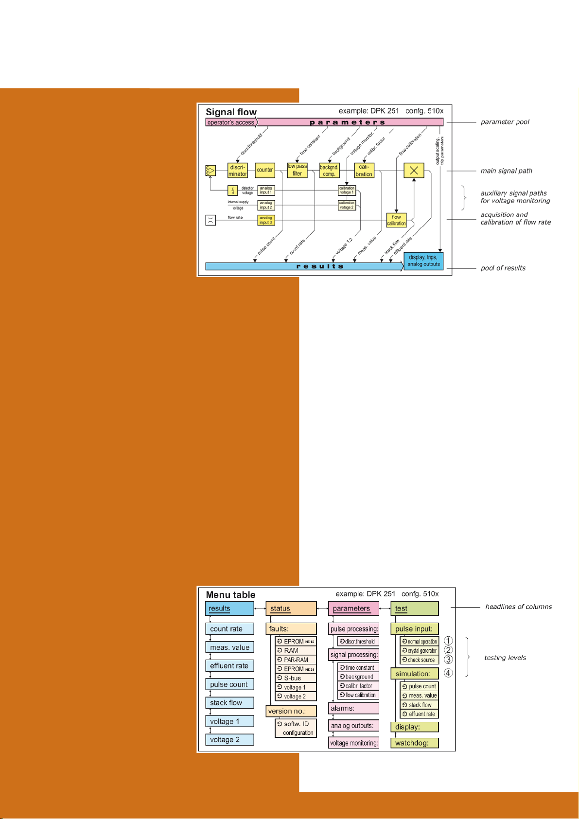
Signal processing has to be
adapted to the individual appli-
cation by adjustable parameters,
like time constant or calibration
factor. Additionally, all measur-
ing values may be monitored by
adjustable alarm thresholds, and
may be used for linear or loga-
rithmic output signals.
Measuring values and param-
eters are organized in two columns of the menu table.
There are other columns, one to activate all the test
procedures and another to show the status informa-
tions of the channel. The 2-line LCD and the keys of
the main processor board NZ 12 enables the access
to all positions of the menu table.
The operator has two different possiblities for the
access to system TK 250 signal processing channels,
either manual via display and function keys on the
front panel of the main processor board NZ 12 or via
the data interface with an external PC. Also during an
operator’s dialog the continuous signal processing
functions are not interrupted. Thus, without external
tools, reading of all measuring values, parameters
and status informations is possible in parallel to the
normal signal processing. Modi cations of para-
meters and activation of test procedures also may
be done on the menu table using the keys, but these
functions are locked and can be
enabled the key switches on the
board NS 01.
TK 250
Signal Processing
TEST PROCEDURES
Functional tests of TK 250 measuring channels in
connection with detectors and output periphery may
be performed on different levels with automatic or
remote operated procedures.
On the base level (1) there is a number of continu-
ous self checks of hardware and software in the
measuring channel. The goal is detecting drifts and
faults very early and verfying the original status of the
software originally type tested. The internal supply
voltage and the detector supply voltage, the detector
signal, the memory for data, parameters and pro-
gram, the data transfers on the internal S-bus, the
execution to the program and some other features
are subject of the continuous self checks. Faults will
cause an alarm status signal and the reason can be
checked in the status column of the menu table.
Page 3

The next level (2) is the check of the complete signal
path beginning at the detector up to the interface to the
external periphery performed with remote check sources
or with ionization chambers with internal check volume.
The third level (3) is testing with electrical signal genera-
tors. Preampli ers and signal input boards have remote
operated pulse or current sources to generate precise
test signals for the input converters.
Finally (4), analog and binary output signals and the
concerning periphery like indicators, recorders or alarm
devices can be activated by numerical signal simulation,
thus the whole range of output signals is covered, fast
and precise. The test mode generates status signal of a
binary output (relay contact).
TK 250
Signal Processing
ELECTRONIC MODULES
The measuring channels of the systems TK 250 are
constructed with 19” modules. Pre-ampli ers and signal
converters for very sensitive detector signals are moun-
ted in separate boxes. There is a variety of input boards
for the pre-processing of the detector signals, e.g. pulse
discriminator NI 21... and ampli er boards NA 31... for
neutron detectors. On the output side there are isolated
buffer ampli ers NT 31 and NT 61 for analog signals and
relay bords for binary signals, e.g. NB 21. The modules
interface, supply and auxiliary functions are assembled
all around the microprocessor boards for signal acquisi-
tion NZ 21 and for signal processing NZ 12.
Page 4

Signal Processing
LIST OF MODULES
Type Designation Function Used For Supply Voltage Width
NA 04/06
NA 07.21
NA 31
NA 32
NA 33
NA 34
NA 36
NB 21
NB 22
NB 28
NE 31
NE 32
NH 32
NH 33
NH 34
NH 36
NH 42
NI 11
NI 21
NI 22.2
NK 21.2
NN 01
NN 41
NN 43
NN 51
NN 53
NN 54
NP 31
NR 17
NR 31
NS 01
NT 31
NT 61
NZ 12
NZ 21
NV 101
NV 102
NV 320
TKV 23
Indicator unit
Pump control unit
Current input unit
Fission chamber unit
RMS input unit
Average value ampli er
SPND input unit
Binary I/O-board
Decoder board
Binary output board
Pulse outputs
Pulse shaper
High voltage supply
High voltage supply
High voltage supply
High voltage supply
High voltage supply
Standard pulse input
Pulse discriminator
Double window discriminator
Serial interface
DC supply network
24 VDC power supply
24 VDC power supply
230 VAC power supply
230 VAC power supply
230 VAC power supply
Test generator
Relay board
Relay board
Key switch board
Isolated buffer ampli er
Isolated buffer ampli er
Main processor board
I/O processor board
c/f converter
c/f converter
Pulse pre-ampli er
Wide range pre-ampli er
1 or 2 analog indicators 24 × 96 mm
Switches and operating hours counter
c/v-converter 0 ... 10/25/50 μA
Detector voltage and c/f-converter
Main ampli er and RMS-correlator
c/v-converter 0 ... 2.5/5 mA
Differential ampli er
DEK 251
DGK 250
DSK 250
DWK 250
DMK 250
DLK 250
4 inputs, 8 relays outputs 60 V/0,5 A
4 bit to 1v16, with level shifter
DAK, DWK
8 relays outputs 125V/1A
2 insulated 50 Ω pulse buffers
Pulse ampli er, e.g. for iodine monitors DEK 251
0 ... 1 kV, 2 mA max.
0 ... 2 kV, 1 mA max.
0 ... 4 kV, 0,5 mA max.
0 ... 500 V, 4 mA max.
0 ... 800 V, 30 mA max. DWK 250
2 insulated inputs
2 integral discriminators
2 single channel discriminators
DEK 251
RS 232 or RS 485, insulated
Redundant supply & battery inputs
Output voltages: 5 V, ±15V
Output voltages: 5 V, ±15V
Output voltages: 5 V, ±15V
Output voltages: 5 V, ±15V
Output voltages: 24 VDC or 28 VDC
Test signal 0 ... 10 V/20 mA adjustable
DMK 250 ±15 V
6 relays, 2 change overs each
16 relays, 2 contacts each
2 key switches, test plugs
1 ... 4 × 0 ... 10V/0 ... 20mA
Various input/output combinations
With display and keys
2 counters, 4 analog I/Os each
0.1 pA … 0.3 μA, 800 V detector supply
0.1 pA … 1mA, various detector voltages
For neutron detectors
For wide range ssion chambers
DAK 250
DWK 250
24 V
±15 V
±15 V
±15 V
±15 V
±15 V
±15 V
±15 V
±15 V
±15 V
±15 V
±15 V
±15 V
±15 V
±15 V
±24 V
5 V, ±15 V
5 V
5 V, ±15 V
5 V
35 VDC max.
18 ... 32 VDC
18 ... 32 VDC
195 ... 255 VAC
195 ... 255 VAC
195 ... 255 VAC
15 or 24V
15 V
5 V
±15 V
24 ... 230 VAC/DC
5 V
5 V, ±15 V
15 ... 32 VDC
15 ... 32 VDC
±15 V
±15 V
8/12 T
8 T
4 T
4 T
4 T
4 T
4 T
4 T
4 T
4 T
4 T
4 T
8 T
8 T
8 T
8 T
14 T
4 T
0/4 T *
0/4 T *
4 T
4 T
4 T
8 T
4 T
8 T
8 T
4 T
4 T
4 T
4 T
4 T
4 T
20 T
0/4 T *
Box
Box
Box
Box
TK 250
notice: T = 2/10” = 5.08 mm
Mirion Technologies (MGPI) SA
Route d’Eyguières
FR-13113 Lamanon
France
T +33 (0) 4 90 59 59 59
F +33 (0) 4 90 59 55 18
Since norms, speci cations and designs are subject to occasional change, please ask for con rmation of the information given in this publication.
Mirion Technologies (MGPI) Inc
5000 Highlands Parkway
Suite 150
Smyrna, GA 30082
USA
T +1 770 432 2744
F +1 770 432 9179
* without front panel, arranged behind NZ 12
Mirion Technologies (MGPI H&B) GmbH
Landsberger Strasse 328a
DE-80687 Munich
Germany
T +49 (0) 89515 13-0
F +49 (0) 89515 13 169
www.mirion.com
144879EN-C
Mirion Commercial (Beijing) Co., Ltd.
Shanghai Jiangchang Commercial Branch
Room 801, 78 Jiangchang SanLu
Zhabei District, Shanghai 200436
PR of China
T +86 21 6180 6920
F +86 21 6180 6924
 Loading...