

Page 1
Featuring:
radiation monitoring
systems
A Mirion Technologies Division
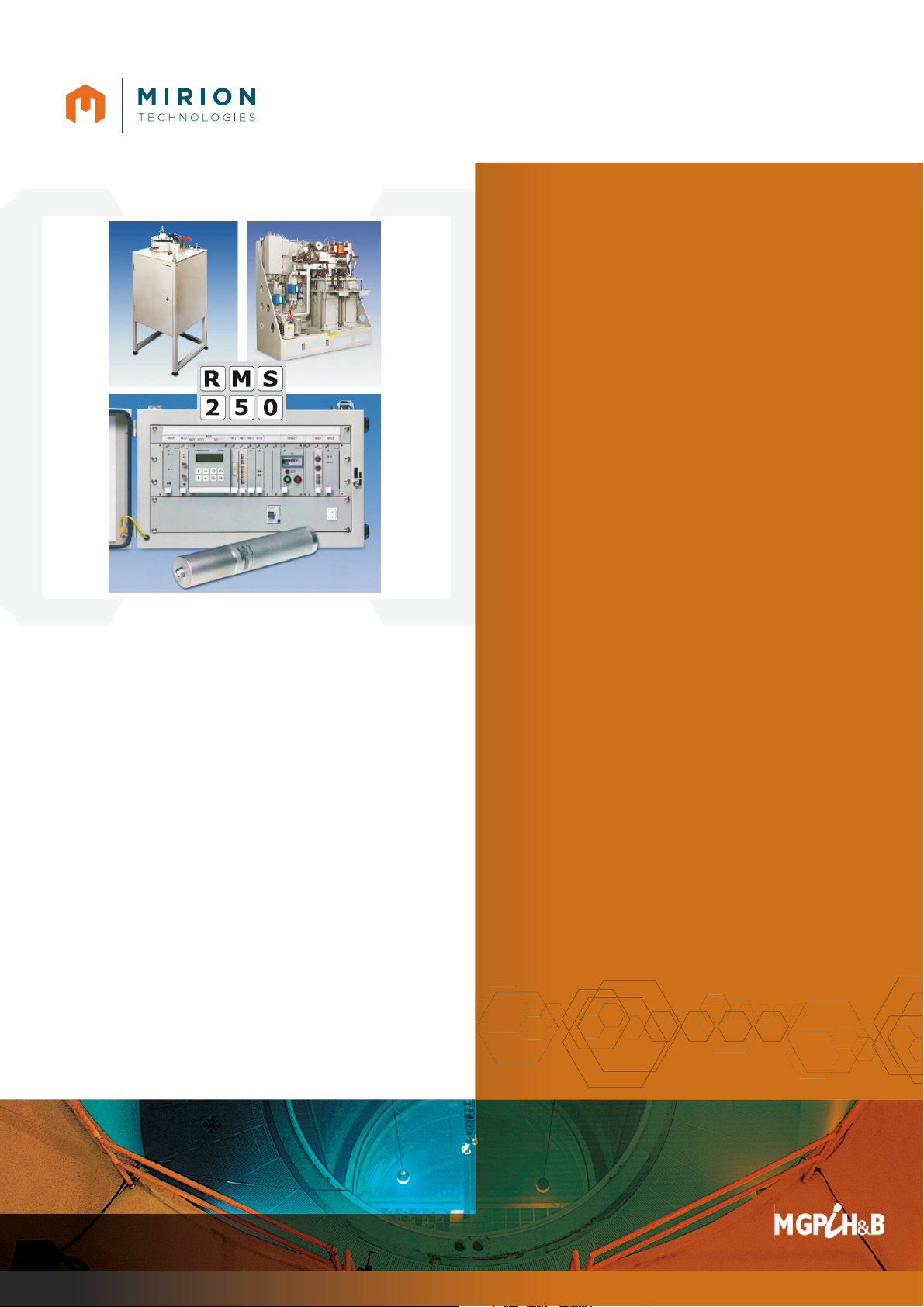
RMS 250
Radiation Monitoring
RMS 250
Radiation Monitoring System
The monitors of the system RMS 250 are designed
for xed installed, safety related measuring channels
classi ed by the German nuclear regulations
KTA 1501 ff and KTA 3501 or similar international
regulations.
APPLICATIONS
• Dose rate monitoring according to KTA 1501
and KTA 1506
• Monitoring of radioactive aerosols, iodine and
noble gases according to KTA 1502 and KTA
1503.1
• Stack monitoring for post accident conditions
according to KTA 1503.2
• Liquid monitoring according to KTA 1504
• Dose rate and activity monitoring for research
reactors according to KTA 1507
• N-16 monitoring for detection of steam generator
leakages according to KTA 3501
FEATURES
Calibrated monitors for radiation protection and
process monitoring assembled with qualifi ed
components:
● Detectors, measuring vessels, lead shieldings
● Cables, signal procesing, test equipment
Page 2

RMS 250
Radiation Monitoring
Dose Rate Monitoring, Area Monitoring according to KTA 1501 and KTA 1506
Meas. Range
(Sv/h)
Detector Detector Temperature Check
Source
Detector Cable Signal Processing Signal Paths
Continuous 1h max.
1e-3 ... 1e+5
1e-5 ... 1e+5
KG 50 SEC
KG 80 PEF
0 ... 135°C
-25 ... 100°C
205°C / 3h
120°C ch. vol.
2 x cer. coax
4 x coaxial
NV102 + DPK251·K2xxx
NV102P + DPK251·K2xxx
1 ... 4
1 ... 4
1e-7 ... 1
1e-6 ... 1
KG 122 SBL
KG 122 PEF
0 ... 80°C
0 ... 100°C 120°C
TKA 17
ch. vol.
2 x coaxial
4 x coaxial
NV102 + DPK 251·K2xxx
NV102P + DPK251·K2xxx
1 ... 4
1 ... 4
1e-7 ... 100
1e-7 ... 100
KG 151 REZ
KG 220 SEU
-25 ... 150°C
-30 ... 120°C
180°C
165°C
TKA 15
TKA 16
2 x coaxial
2 x coaxial
NV102 + DPK 251·K2xxx
NV102 + DPK251·K2xxx
1 ... 4
1 ... 4
1e-7 ... 0.3 KG 220 EEM 0 ... 80°C TKA 16 2 x twist.pair DPK 251 K12xx/14xx 1 ... 4
1e-7 ... 1e-2 ZG 50 A1 -25 ... 70°C TKA 52 2 x twist.pair DPK 251 K12xx/14xx 1 ... 4
Monitoring of Radioactive Noble Gas according to KTA 1502 and KTA 1503.1
Meas. Range for
Xe-133 (Bq/m3)
Detector Measuring
Vessel
Lead Shelding Check
Source
Detector
Cable
Signal Processing Signal Paths
2e+3 ... 1e+9
1e+4 ... 1e+10
SB 150
SB 40
RSD 275
RSD 200
RSA 481/482
RSA 310/311
TKA 61
TKA 61
TKK 05
TKK 05
DPK 251·K52xx/54xx
DPK 251·K52xx/54xx
1 ... 4
1 ... 4
Liquid Monitoring according to KTA 1504
Meas. Range for
Cs-137 (Bq/m3)
Detector Meas. Vessel
or Principle
Lead
Shelding
Check
Source
Detector
Cable
Signal Processing Signal
Paths
3e+3 ... 3e+8
5e+3 ... 1e+9
typ. 1e+4 ... 1e+10
SG 65 M
SG 65 M
SG 65 M
RSD 135
RSD 221
Off line
RSA 428
Proj. spec.
TKA 54
TKA 54
TKA 54
TKK 05
TKK 05
TKA 05
DPK 251·K52xx/54xx
DEK 251 / DPK 251
DPK 251·K52xx/54xx
1 ... 4
1 ... 4
1 ... 4
Monitoring of Radioactive Aerosols and Iodine according to KTA 1502 and KTA 1503.1
Detected
Activity
Measuring Range
(Bq/m3)
Monitor and Detector Check
Source
Detector Cable Signal Processing Signal
Paths
Beta aerosols
Gamma aerosols
Iodine
2 ... 1e+5 for Cs-137
1 ... 1e+4 for Cs-137
1 ... 1e+4 for I-131
AD 24
AG 24
JD 24
SB 40
SG 65 M
SG 65 M
TKA 47
TKA 47
TKA 10
TKK 05
TKK 05
TKA 05
DPK 251·K10x
DPK 251·K30x
DPK 251·K40x
1
1
1
Monitoring of Steam Generator Leakages according to KTA 3501
Detected
Activity
Measuring Range
(Bq/m3)
Monitor and Detector Check
Source
Detector Cable Signal Processing Signal
Paths
N-16 Main steam line 1 ... 1e+5 SG 66 TKA 54 TKK 05 DAK 250-i 1
Stack Monitoring for Post Accident Conditions according to KTA 1503.2
Detected
Activity
Measuring Range
(Bq/m3)
Monitor Detector Check
Source
Detector Cable Signal Processing Signal
Paths
Aerosols
Iodine-131
100 ... 2e+8 (1e+11)
20 ... 2e+7 (8e+11)
FA/J 51 SG SG 65 M TKA 63 TKK 05 DEK 251.K20x 3
Xenon-133 1e+8 ... 1.5e+14
8e+5 ... 3.7e+15
RSD 211
(NGM 203)
KB 100
CHMC 01
TKA 61
TKA 70
TKK 12 NV102 + DPK251
NV103 + DPK251
1 ... 4
1 ... 4
Page 3

RMS 250
Radiation Monitoring
DETECTORS
A variety of type tested detectors is available to
transform the physical quantity “nuclear radiation”
(e.g. particle ux or dose rate) into a electrical signal:
• Gamma ionization chambers for dose rate monito-
ring
• Beta ionization chambers for noble gas monitoring
• Gamma and beta scintillation detectors for activity
monitoring
• Large-area silicon detectors for alpha and beta
monitoring
• GM-detectors for simple applications
• BF3 proportional counter tubes for sensitive
neutron monitoring
DIGITAL SIGNAL PROCESSING CHANNELS
Digital electronic channel systems TK 250 are
designed for signal processing of dose rate and
activity monitors. They are characterized by ef cient
functions, a comfortable operators menu structure
and a reliable and rugged operational behaviour.
Hardware and software are organized in modules.
This results in a high exibility to adapt to different
applications and customer needs.
Interfacing of pulse detectors and ionization
chambers is achieved by different preampli ers or
input boards. Remote operated test generators on
the input boards and signal simulation at different
points of the digital
processing sequence
allow ef cient proce-
dures for periodical
testing.
Hardware and software
of the system are type
tested according to
KTA 1505 and KTA
3505, therefore it may
be used for functions
of category A and B of
IEC 61226.
Page 4

Since norms, speci cations and designs are subject to occasional change, please ask for con rmation of the information given in this publication.
Mirion Technologies (MGPI) SA
Route d’Eyguières
FR-13113 Lamanon
France
T +33 (0) 4 90 59 59 59
F +33 (0) 4 90 59 55 18
Mirion Technologies (MGPI) Inc
5000 Highlands Parkway
Suite 150
Smyrna, GA 30082
USA
T +1 770 432 2744
F +1 770 432 9179
Mirion Technologies (MGPI H&B) GmbH
Landsberger Strasse 328a
DE-80687 Munich
Germany
T +49 (0) 89515 13-0
F +49 (0) 89515 13 169
Mirion Commercial (Beijing) Co., Ltd.
Shanghai Jiangchang Commercial Branch
Room 801, 78 Jiangchang SanLu
Zhabei District, Shanghai 200436
PR of China
T +86 21 6180 6920
F +86 21 6180 6924
RMS 250
Radiation Monitoring
www.mirion.com
144982EN-B
SIGNAL PROCESSING CHANNELS for different
applications:
DPK 251 Digital Pulse Channel for dose rate and
activity monitoring with 2 or 4 signal paths
DFK 251 Digital Filter Channel for particulate and
iodine monitors
DEK 251 Digital E uent Monitoring Channel e.g.
for post accident monitors
DAK 250 Digital Start-up Channel for applications in
category A
INPUT SIGNALS
● Detector pulses: > 30 ns up to 5e6 cps
● 5V standard pulses: >1 µs up to 4e5 cps
● DC currents: from 0.1 pA to 1 mA
● Analog signals: 0/4 ... 20 mA
● Binary signals:
○ 24V-logic, contacts, NAMUR-Sensors
● Detector supply:
○ 0 ... 1 kV, 2 mA or 0 ... 2 kV, 1 mA or 0 ... 4 kV, 0.5 mA
POWER SUPPLY
● 18 ... 33 VDC, approx. 1.6A at 24 VDC or
● 230 VAC or 115 VAC +10%/-15%; 48...62 Hz,
approx. 40 VA
OUTPUT SIGNALS
● Linear or logarithmic analog outputs:
○ Measuring range to be adjusted with parameters
○ 0 ... 10 V internal, optional analog indicator
○ 0 or 4 ... 20 mA, 0 ... 600 Ω load, oating
● Up to 20 different alarms, adjusted by parameters:
○ Low or high alarm to be selected for all variables
○ Threshold and hysteresis adjustable
● Binary outputs, e.g. for alarms, status signals
relay change overs, 60V/0.5A or 125V/1A
ENVIRONMENTAL CONDITIONS
● Ambient temperature (modules): 0 ... 70°C
(32 ... 158°F)
● Storage temperature: -30 ... 85°C (-22 ... 185°F)
● Humidity: < 95%
● Seismic conditions: ≤5 g, 5 ... 100 Hz
● Mechanical stress: ≤30 g, 11 ms
MECHANICAL CONSTRUCTION
● 19” modular system according to IEC 60297
● Printed board size: 100 mm × 160 mm (3.9 in x 6.3 in)
● Front panels: 20 mm × 128 mm (0.8 in x 5 in)
or multiples
● Rack size (W×H×D): 483 mm × 133 mm × 280 mm
(19 in x 5.2 in x 11 in)
½-19” wall mount housing
19”-6U wall mount housing
 Loading...