

Page 1

OPERATING MANUAL
MBD-2 (IM-278/U)
Personal Dosimeter
Document # 15-00167
Revision 1
December 2018
Page 2

Table of Contents
1. Preparation for Storage or Shipment .................................................................................................... 5
2. Introduction ............................................................................................................................................ 6
3. Description ............................................................................................................................................ 6
3.1 Physical Desc r iption .......................................................................................................................... 6
4. Operation ............................................................................................................................................... 8
4.1 Principle of Operation ........................................................................................................................ 8
4.2 Installing the Wrist Strap ................................................................................................................... 9
4.3 Batteries .......................................................................................................................................... 11
4.3.1 Removal/Replacement of the Main Battery ................................................................................ 11
4.3.1.1 Main Battery Replacement ...................................................................................................... 11
4.3.1.2 Battery Display Indications: ..................................................................................................... 13
4.4 Start-up and Diagnostics ................................................................................................................. 15
4.4.1 Start-up ........................................................................................................................................ 15
4.4.2 Diagnostics .................................................................................................................................. 15
4.4.3 Operation ..................................................................................................................................... 16
4.4.4 Display Messages ....................................................................................................................... 16
5. Reading Data from the MBD-2 ............................................................................................................ 17
6. Maintenance ........................................................................................................................................ 17
6.1 O-Ring ............................................................................................................................................. 17
6.1.1. Inspection and Replacement....................................................................................................... 17
6.2 Internal Battery (Detector & RTC) Replacement ............................................................................. 18
6.3 C-Rings ........................................................................................................................................... 20
7 Troubleshooting .................................................................................................................................. 22
7.1 Display Messages ........................................................................................................................... 22
7.1.1 Display Messages: Problems and Resolutions ........................................................................... 22
7.1.2 Parameter Error Codes: Problem and Resolution ...................................................................... 23
8. Technical Specifications ...................................................................................................................... 27
8.1 Radiological Characteristics ............................................................................................................ 27
8.2 Physical Characteristics .................................................................................................................. 27
8.3 Environmental Characteristics ........................................................................................................ 27
8.4 Electrical Characteristics ................................................................................................................. 27
9. Parts .................................................................................................................................................... 28
10. Dimensional Drawing ...................................................................................................................... 29
MBD-2 Operating Manual 2
15-00167, Rev 1
Page 3

List of Figures
Figure 1: MBD-2 Personal Dos imeter System .............................................................................................. 7
Figure 2: MBD-2 Physical Features .............................................................................................................. 7
Figure 3: MBD-2 Board with Detector Placement (relative to case) ............................................................. 7
Figure 4: MBD-2 Wrist Strap ......................................................................................................................... 9
Figure 5: Wrist Strap Orientation & Assembly .............................................................................................. 9
Figure 6: Preparing the Wrist Strap ............................................................................................................ 10
Figure 7: Donning the MBD-2 and Securing the Wrist Strap ...................................................................... 10
Figure 8: MBD-2 Battery Cover Removal ................................................................................................... 11
Figure 9: O-Ring Location ........................................................................................................................... 11
Figure 10: MBD-2 Battery Compartment and Markings .............................................................................. 12
Figure 11: MBD-2 Correctly Installed Battery Position ............................................................................... 12
Figure 12: MBD-2 and Main Battery Cover Thread Stops .......................................................................... 13
Figure 13: Battery Power Icon .................................................................................................................... 13
Figure 14: MBD-2 with Active Displa y ......................................................................................................... 16
Figure 15: MBD-2 with O-Ring Removed ................................................................................................... 18
Figure 16: MBD-2 without O-Ring and Inspection ...................................................................................... 18
Figure 17: MBD-2 with Installed O-Ring ..................................................................................................... 18
Figure 18: Internal Battery Cover and Compartment .................................................................................. 19
Figure 19: Installing the Internal Battery Cover........................................................................................... 20
Figure 20: C-Ring Removal......................................................................................................................... 21
Figure 21: C-Ring Replacement ................................................................................................................ 21
Figure 22: MBD-2 Replacement Parts ........................................................................................................ 28
List of Tables
Table 1: MBD-2 Detector and Range Table .................................................................................................. 8
Table 2: MBD-2 Battery Icon Segments ..................................................................................................... 13
Table 3: MBD-2 Battery Display Messages ................................................................................................ 14
Table 4: MBD-2 Start-up & Diagnostics ...................................................................................................... 15
Table 5: MBD-2 Display Messages ............................................................................................................. 16
Table 7: Display Message Table ................................................................................................................. 22
Table 8: Parameter Error Code Table ......................................................................................................... 23
MBD-2 Operating Manual 3
15-00167, Rev 1
Page 4

FCC Compliance S t atement
This device complies with part 15 of the FCC Rules. Operation is subject to the following two conditions:
1. This device may not cause harmful interference, and
2. This device must accept any interference received, including interference that may cause undesired
operation.
Modifications: Any modifications made to this device that are not approved by Mirion Technologies Oy
may void the authority granted to the user by the FCC to operate this equipment.
Note: This equipment has been tested and found to comply with the limits for a Class B digital device,
pursuant to Part 15 of the FCC Rules. These limits are designed to provide reasonable protection against
harmful interference in a residential installation. This equipment generates, uses and can radiate radio
frequency energy and, if not installed and us ed in acc or dance w ith the instr uct ions, may cause harmful
interference to radio communications. However, there is no guarantee that interference will not occur in a
particular installation. If this equipment does cause harmful interference to radio or television reception,
which can be determined by turning the equipment off and on, the user is encouraged to try to correct the
interference by one or more of the following measures:
• Reorient or relocate the receiving antenna.
• Increase the separation between the equipment and receiver.
• Connect the equipment into an outlet on a circuit different from that to which the receiver is
connected.
• Consult the dealer or an experienced radio/television technician for help.
Precautions concerning the use of 3V Lithium
Batteries
• Do not attempt to recharge or reenergize batteries.
• Exhausted batteries immediately shall be removed as soon as practical to prevent damage from
leaking batteries
o If batteries have leaked (dry or wet white residue), use personnel protective equipment such as
hand and eye protection to remove and clean.
• Do not dispose of batteries in fire.
• Do not dismantle batteries.
MBD-2 Operating Manual 4
15-00167, Rev 1
Page 5

1. Preparation for Storage or
Shipment
The following procedure is to be used if your MBD-2 must be stored or shipped for any
reason. First, remove the main battery (Section 3.2.1.1). Pack the complete MBD-2 along
with the proper maintenance documentation and turn it in to your Property Book Officer
(PBO) for shipment. PBO confirms the MBD-2 is packed properly.
1.1 Preparation for Long Term Storage
In hot, humid climates, the MBD-2 should be caref ul l y clean ed with a small amount of
isopropyl alcohol on a clean cloth to remove any skin oils that could support fungal growth.
Wipe down all visible surfaces.
MBD-2 Operating Manual 5
15-00167, Rev 1
Page 6

2. Introduction
The MBD-2 Personal Dosimeter is a device which incorporates the benefits of passive
radiation detection with active, self-reading and recording functionality. The MBD-2 has no
pushbuttons, switches, speaker, or LED and requires no user intervention for operation. The
MBD-2 is pre-configured for rapid issue from storage. The battery powered device includes
on-board digital processing to provide a self-reading, accurate and reliable dose
measurement on an integrated, non-reflective LCD display. Battery power level is reported on
the display using an interactive icon found in commercial electronics. Radiation
measurement data is recorded in device memory every 12 hours.
The MBD-2 provides radiation dose information to the wearer in the field. The MBD-2
displays the total deep absorbed dose D(10) (sum of deep gamma and deep neutron) and is
displayed in measurement units of cGy and Gy.
The MBD-2 uses Direct Ion Storage (DIS), Pin Diode and MOSFET detector technology
passive detectors. The passive DIS radiation detectors are continuously responsive to
radiation, with or without the field-replaceable main battery. The internal electronics provide
self-reading measurement display, digital memory, data logging, on-board diagnostic testing
during startup and NFC (Near Field Communication) read-only wireless communication. All
data resides in non-volatile memory for dose-of-record processing so there is no any danger
of losing stored data or configuration settings on main battery failure. The diagnostics
measure and display battery conditions and fault conditions of the device.
The MBD-2 is a sealed device for durability and hardness. There are no serviceable internal
parts. Maintenance parts are accessible and replaceable.
3. Description
3.1 Physical Descri ption
The MBD-2 personal dosimeter system is designed to be worn on the wrist w ith a 15- inch
hook and loop wrist strap. The MBD-2 can also be worn on the trunk of body (clipped to
lanyard, pocket, etc.). In this use case, the proper MBD-2 orientation is the display facing
away from the body.
The MBD-2 features a non-backlit LC D dis play, wireless (NFC read-only) communication,
adjustable wristband, and replaceable batteries.
The main battery compartment is accessible through a removable, self-securing battery cover
located on the back of the device. A sealed compartment below the main battery contains
additional batteries used to provide power to the DIS detectors and real-time clock (RTC).
The main battery compartment incorporates an O-ring seal to secure the battery from the
external environment.
MBD-2 Operating Manual 6
15-00167, Rev 1
Page 7

1. LCD Display
3. C-Ring (2) for Wrist strap
2. Screen Protector and Label
4. Battery Compartment Cover
Figure 1: MBD-2 Personal Dosimeter System
Figure 2: MBD-2 Physical Features
MBD-2 Operating Manual 7
15-00167, Rev 1
Figure 3: MBD-2 Board with Detector Placement (relative to case)
Page 8

Detector Type
Detector Code
Range
Deep
Gamma
DIS High Range
DH
0.1 cGy – 600 cGy
Deep
Neutron
ɣ+ n DIS
NL
0.001 cGy – 60 cGy
ɣ DIS
NG
0.001 cGy – 60 cGy
0.01 cGy – 14 cGy Cf-252 Moderated
0.01 cGy – 36 cGy Cf-252 Unmoderated
Tactical Pin Diode
NA
0.001 – 1250 cGy
The MBD-2 includes six separate detector elements:
• Three (3) elements for gamma measurements,
• Three (3) elements for neutron measurements.
Each detector element is listed below in Table 1, MBD-2 Detector and Range Table.
Displayed results including gamma (DA) or neutron (NA) accident detector elements are
provided in centigray (cGy) measurement units.
Table 1: MBD-2 Detector and Range Table
DIS Low Range DL 0.001 cGy – 60 cGy
–
Tactical MOSFET DA 1 cGy – 2500 cGy
–
Calculational Neutron Dose NG/NL
4. Operation
4.1 Principle of Operation
When the main battery is installed, the MBD-2 will power on, activate the LCD display,
initialize and perform diagnostics and operate according to its configurati on. See Section
4.4.2.
During operation, the MBD-2 continuously displays total absorbed dose (as measured),
battery status and periodic self-diagnostic checks. In the event of a device malfunc tion, an
error message will be displayed on the LCD as shown in Section 4.4.4, Common Display
Messages.
The MBD-2 will alert the wearer to the status of battery life by display battery icon and message, as shown in Section 4.3.1.3, Battery Display Indication.
When the main battery is depleted or removed, the MBD-2 detector elements continue to
respond to a radiation field. The detector elements remain active as they are powered by two
internal batteries. When restoring the main battery power, the MBD-2 will display the dose
measurement(s) including any exposure received during the time it was without main battery
power, however, the internal history will not account for the date and time of the
measurements while the main battery power was off.
MBD-2 Operating Manual 8
15-00167, Rev 1
Page 9

4.2 Installing the Wrist Strap
The Wrist Strap is a simple, durable accessory for affixing the MBD-2 to a wrist. The Wrist
Strap uses hook and loop material with a C-shaped ring to facilitate eas y donning and
securing to an outer garment sleeve.
a. Inspect the Wrist Strap seams for visibly loose stitching and frayed edges. Set aside any
Wrist Strap that app ears wor n.
Figure 4: MBD-2 Wrist Strap
b. Install the Wrist Strap by feeding the coarse “Hook” end through the bottom (6 o’clock
position) C-ring.
c. Loop the Wrist Strap through C Rings in the orientation as shown below – smooth side
facing away from the back case as shown in Figure 5: Wrist Strap Orientation and
Assembly.
Figure 5: Wrist Strap Orientation and Assembly
MBD-2 Operating Manual 9
15-00167, Rev 1
Page 10

E
F
d. Feed the Wrist Strap through its own ring to form a loop as shown below.
e. Pull the strap all the way through until it stops at the black metal loop. Feed the course
hook end back though the metal loop as shown below in Figure 6, Preparing the Wrist
Strap.
Figure 6: Preparing the Wrist Strap
f. Insert hand through the loop, pull the strap around itself and securely fasten as shown
below in Figure 7, Donning the MBD-2 and Securing the Wrist Strap
Figure 7: Donning the MBD-2 and Securing the Wrist Strap
MBD-2 Operating Manual 10
15-00167, Rev 1
Page 11

4.3 Batteries
4.3.1 Removal/Replacement of the Main Battery
4.3.1.1 Main Battery Replacement
a. Prior to replacing the battery, remove the wristband from at least one C-Ring so that the
battery cover is accessible.
NOTE: Battery change should not take place under direct rain-like conditions as water inside the battery compartment may cause premature battery discharge.
b. Turn the battery cover counter-clockwise to remove.
Figure 8: MBD-2 Battery Cover Removed
c. Verify the presenc e of the O-Ring. Inspect for integrity. See Section 6, Maintenance, for
additional O-Ring information.
Figure 9: O-Ring Location
d. Remove the main battery
e. Dispose the used battery in accordance with site requirements.
MBD-2 Operating Manual 11
15-00167, Rev 1
Page 12

Battery Orientation:
Positive (+) Side Up
Battery Model: CR2450N
(Renata brand recommended)
Figure 10: MBD-2 Battery Compartment and Markings
f. The battery compartment features imprints of battery orientation and model number.
g. Insert a new battery (Model CR2450, Renata brand preferred) into the compartment,
positive (+) side facing up, as shown below in Figure 11, MBD-2 Correctly Installed
Battery Position.
h. Confirm the presence of the O-ring prior to installing the battery cover. Ensure the O-Ring
is not twisted, warped or worn and that it lays flush on the surface flange. Refer to
Section 6.1, O-Ring for guidance.
i. Install the battery cover by turning clockwise.
The MBD-2 case and battery cover are designed with thread stops, as shown below in
Figure 12, MBD-2 and Main Battery Cover Thread Stop, to prevent wear and stripping
of the threads and also ensure a secure fit.
When installed and turned clockwise, the battery cover will stop in place when the threadstop is engaged.
MBD-2 Operating Manual 12
15-00167, Rev 1
Figure 11: MBD-2 Correctly Installed Battery Position
Page 13

Segments
Status
Voltage
Figure 12: MBD-2 and Main Battery Cover Thread Stops
4.3.1.2 Battery Display Indications:
The MBD-2 reports Main Battery power status with a standard battery icon:
Figure 13: Battery Power Icon
The icon segments, as shown below in Table 2, MBD-2 Battery Icon Segments, represent
the following power status:
Table 2: MBD-2 Battery Icon Segments
100% to 51% range Max to 2601 mV
51% to 26% range 2600 to 2401 mV
25% to 1% range 2400 to 2201 mV
MBD-2 Operating Manual 13
15-00167, Rev 1
Page 14

When the battery voltage is below 25% (approximately < 2400 mV), the MBD-2 will report
battery low power status on the display in the following conventions as shown below in Table
3: MBD-2 Battery Display Messages:
Table 3: MBD-2 Battery Display Messages
Battery Display Message Condition
Main PbAt permanent on display
Detector
Real-Time Clock
Note: there is no Low Battery message for the Main Battery. The battery icon provides visual
status.
Main Battery exhausted, replace
dbAt cycles display screen
dbAt permanent on display
No message Change with Detector Batte r ies
Detector Batteries are critically low (<25%)
Detector Batteries are exhausted, replace
MBD-2 Operating Manual 14
15-00167, Rev 1
Page 15

4.4 Start-up and Diagnostics
4.4.1 Start-up
When the battery is installed, the MBD-2 powers on. There are no switches to power on or off
the MBD-2.
4.4.2 Diagnostics
During start-up, the MBD-2 performs diagnostics and then becomes active with a live display.
Table 4 below describes the visual start-up operation:
Table 4: MBD-2 Start-up & Diagnostics
Start-up Operation and Effect LCD Display Indication
All LCD Segments illuminate for 3 seconds
Installed Firmware version (example)
Diagnostics Check OPEr (Operating Mode)
no.Er message indicates no errors have been identified.
If the MBD-2 becomes operational following an Error
during start-up, the PA.Er message will appear on the
Display, indicating an Error was recorded.
Initialization init
Measurement display: Dose Value (measurement value).
The Deep Total value displayed is a sum of the Gamma
and Neutron dose measurements.
NOTE: The MBD-2 may be stored with or without a main battery. When storing with a battery,
background radiation will accumulate dose to the detectors and record data to memory.
MBD-2 Operating Manual 15
15-00167, Rev 1
Page 16

OF:t
OF:n
4.4.3 Operation
The default LCD configuration displays Total Deep Dose (sum of Gamma and Neutron) and
cGy measurement units.
Figure 14: MBD-2 with Active Display
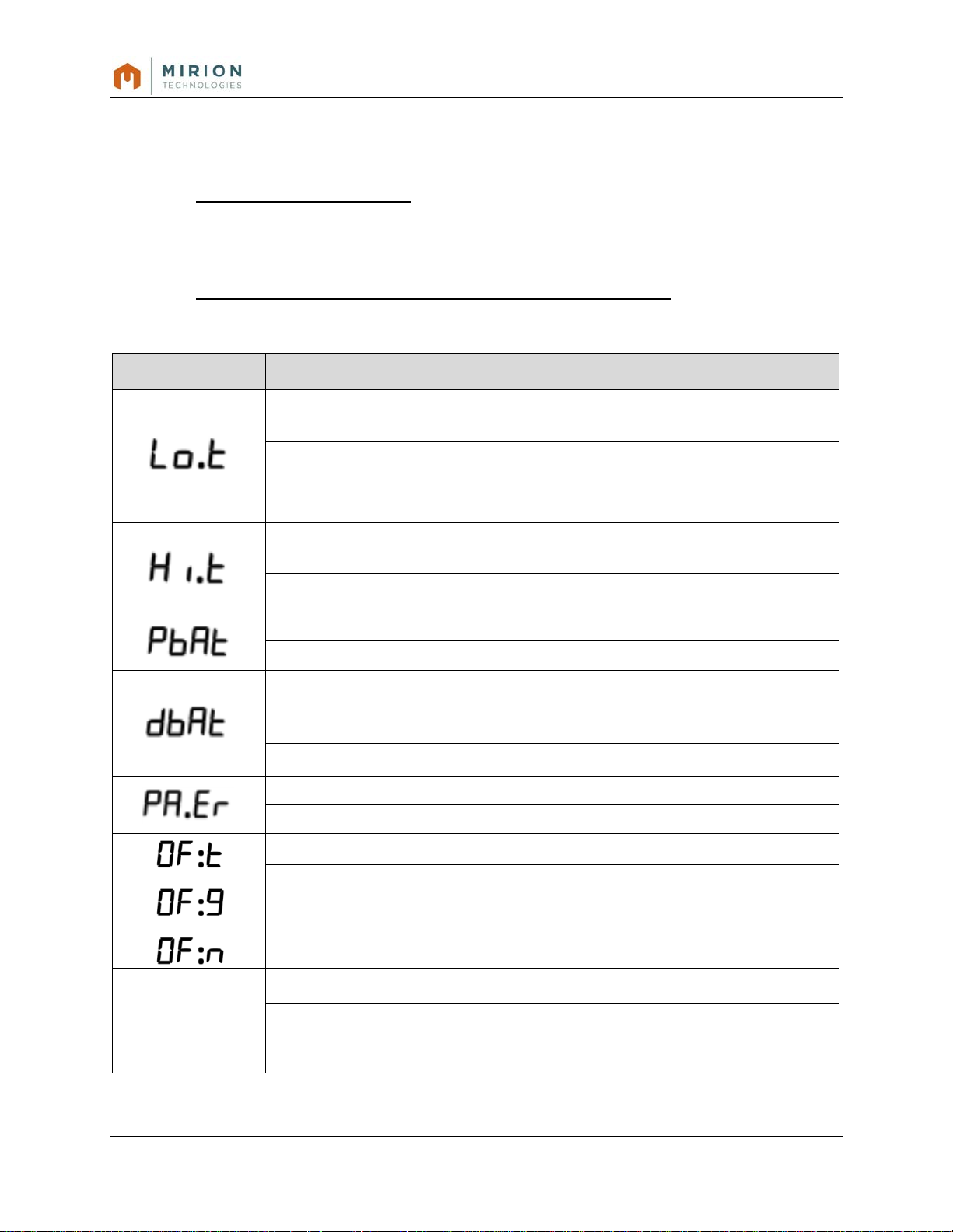
4.4.4 Display Messages
The MBD-2 may display messages or characters on the LCD under certain conditions of
operation:
Table 5: MBD-2 Display Messages
Message Condition
Lo.t
Hi.t
PbAt
dbAt
PA.Er
OF:G
Operating temperature is below the lower temperature threshold (-10°C)
Operating temperature is above the upper temperature threshold (+50°C)
The Main Battery voltage is exhausted
The Detector Batteries voltage is low or exhausted
A parameter error has been detected.
One or more detectors is over-range or has been saturated
See Section 7, Troubleshooting for Display Message information.
MBD-2 Operating Manual 16
15-00167, Rev 1
Page 17

5. Reading Data from the MBD-2
The MBD-2 is a read-only device. Measurement data that is recorded and stored in the
MBD-2 memory can be transferred using a “smart” reader device (i.e.; smartphone with
software application [“App”]).
Measurement data is saved in MBD-2 resident memory and the newest values over period of
15 days is maintained in the NFC chip memory. The MBD-2 is configured to perform two daily
“reads”, where a dose or measurement record is saved to memory including a date and time
stamp. These records are maintained on the MBD memory and the NFC memory chip until
the space allotment is filled. Once the data is transferred, new data records are recorded into
the available space (i.e.; cyclic memory).
“Instant” data can be transferred from the MBD-2. When a reader device communicates with
the MBD-2 NFC chip, an instant read is initiated and the most current log data recorded will
be transferred with current total dose measurement. This can take place only when there is
dose value given on the display. So during ‘init’ phase or if the main battery is removed /
exhausted, no current dose value is available.
When an external NFC reader device is used, the data is transferred from the dosimeter over
the air in binary format. Using Mirion standard reader application, the results can be sent as
text files and transferred from the Smartphone to a computer for further action.
Data formats and NFC protocol information is available in external documentation.
6. Maintenance
6.1 O-Ring
The O-Ring provides the battery compartment a barrier and protection from moisture and dust intrusion. The O-Ring should be:
a. Confirmed to be in place whenever the main battery cover is opened
b. Inspected for condition when replacing the main battery.
6.1.1. Inspection and Replacement
a. Remove and inspect the O-Ring for indications of wear and degradation, to include, cuts,
shedding, twisting, or uneven placement.
MBD-2 Operating Manual 17
15-00167, Rev 1
Page 18

Figure 15: MBD-2 with O-Ring Removed
b. Ensure surface area for the O-Ring is clean.
Figure 16: MBD-2 without O-Ring and Inspection
c. Install the O-Ring on the flange. Run a fingertip around the top of the O-Ring to ensure it
is seated properly as shown in Figure 17, MBD-2 with Installed O-Ring below.
Figure 17: MBD-2 with Installed O-Ring
6.2 Internal Battery (Detector & RTC) Replacement
The internal battery cover should be opened onl y unde r a controlled environment.
Careful maintenance shall be ensured to prevent:
• misplacement of parts (screws securing the internal battery cover)
• contamination of the battery contact springs, which have direct access to the internal
electronics.
a. Remove the main battery cover and main batt ery in accordance with Step 3.2.1.1.
b. The Internal battery cover has three “Torx” pattern, size T6 screws.
MBD-2 Operating Manual 18
15-00167, Rev 1
Page 19

1
Internal Battery Cover
4 Detector Battery CR1025, 2 each
2
Torx (T6) screw 3each
5 Real Time Clock (RTC) Battery, 1 each
3
Main Battery Compartment
6 Battery Orientation Markings
WARNING
1
2
4 5 3
6
c. Remove the screws and set the cover aside on a clean surface.
NOTE: the screws can be withdrawn without removal where the elastomer gasket material on
the battery cover will hold the screw in place permitting removal, thus minimizing the risk of
screw misplacement.
Figure 18: Internal Battery Cover and Compartment
d. Replace two detector batteries and one RTC battery using Model CR1025, Renata
preferred. Ensure battery orientation is Positive (+) side up. The internal battery case
features imprints for battery orientation and model number.
If the batteries appear to have leaked, i.e.; there is white residue on the battery
and/or internal battery compartment surfaces; use personnel protective
equipment (i.e.; gloves, safety glasses, etc.) as applicable.
e. Dispose the used batteries in accordance with site requirements.
Note: the detector and real-time clock batteries shall be replaced together during scheduled
maintenance.
MBD-2 Operating Manual 19
15-00167, Rev 1
Page 20

WARNING
Both detector batteries must be replaced.
f. Prior to installing the battery cover:
• Inspect the battery cover for cracks.
• Inspect the gasket for wear or missing segments.
WARNING
The internal battery cover must be replaced if there is evidence of damage
and/wear that would preclude protection of the internal batteries.
g. Install the internal battery cover by positioning over the compartment and installing the
three Torx head screws. The screws are secure when the battery cover is seated and
flush with the case surface as shown below in Figure 19, Installing the Internal Battery
Cover
Figure 19: Installing the Intern al Battery Cover
WARNING
• Do not overtighten the screws as damage can occur to the battery cover and
case threads.
• Use only the prescribed Torx T6 screw, use of screw types will damage the
h. Install the main battery in accordance with 3.2.1.1, steps f-h.
threads.
• Never use power tools to install the screws.
6.3 C-Rings
The C-Ring is 1.9mm thick stainless steel ‘C” shaped loop which is affixed to the MBD-2 by
two insertion holes on opposite ends of the device case. The C-Rings are used for attaching
a wrist strap or other accessory. To remove and/or replace the C-Ring:
MBD-2 Operating Manual 20
15-00167, Rev 1
Page 21

a. Obtain a Snap-Ring plier or similar tool that will facilitate easy removal of the C-Ring. The
adjustable tines on the Snap-Ring plier tool should be extended to allow expansion, when
squeezed, so that it will be slightly wider than the width of the C-Ring.
b. Lift one end of the ring from the insertion hole and angle away to remove the C-Ring as
shown in Figure 3-3: MBD C-Ring Rem oval.
Figure 20: C-Ring Removal
c. To replace the C-Ring, grip the loose C-Ring with the Snap-Ring plier tool. Ensure that
when squeezing the Snap-Ring plier tool, the width of the C-Ring will be slig htly wider than
the case to facilitate easy replacement as shown in Figure 21: C Ring Replacement.
d. Position one side of the C-Ring into the insertion hole, then the other side.
e. Release the Plier tool so that the C-Ring is now secure.
f. Swivel the C -Ring to ensure fit.
Figure 21: C-Ring Replacement
MBD-2 Operating Manual 21
15-00167, Rev 1
Page 22
7 Troubleshooting
7.1 Display Messages
The MBD-2 will display messages or characters on the LCD display during certain conditions. This section describes the displayed messages, their meaning and how to correct:
7.1.1 Display Messages: Problems and Resoluti ons
Table 6: Display Message Table
Display Message Problem / Resolution
Problem: Operating temperature is below the lower temperature threshold of
-10°C. During this condition, the read-out process is not performed.
Resolution: Move device to a warmer environment. This can be within a pocket,
inside layers of a garment. Once the temperature is stabilized, the Lo.t message
is removed.
Problem: Operat ing temperature is above the upper temper ature thres hold of
+50°C. During this condition, the read-out process is not performed.
- - - -
(four dashes)
Resolution: Move the device to a cooler environment
Problem: If PbAt permanent on display, battery exhausted
Resolution: Replace with a new CR2450 battery, Section 3.2 Batteries
Problem:
• If dbAt cycling on the display, less 25% life remains
• If dbAt permanent on display, battery exhausted
Resolution: Replace with 3 new CR1025 battery, Section 3.2 Batteries
Problem: A Parameter Error has been detected, Section 6.1.2 Error Code Table
Resolution: Remove device from service. Return for Warranty Repair
Problem: One or more detectors has reached saturation
Resolution:
• OF:t Overflow Total Dose: the total dose has reached/exceeded 3,750 cGy
• OF:G Overflow Gamma: the gamma dose has reached/exceeded 2,500 cGy
• OF:n Overflow Neutron: the neutron dose has reached/exceeded 1,250 cGy
Problem: One or more detectors cannot report a measurement value(s)
Resolution: Remove device from service. Remove and replace battery and
observe display. If the problem persists, return device for Warranty Repair
MBD-2 Operating Manual 22
15-00167, Rev 1
Page 23

Parameter Error Code
Problem / Resolution
7.1.2 Parameter Error Codes: Problem and Resolution
Table 7: Parameter Error Code Table
Problem: After a system reset, result memory is found to be
inaccessible and the device resets itself. If no element
1
2 Battery i s Exhausted
3 REG UP Timeout
Result memory access failed
measurement has been successful before three self-resets (see
exception 7), the reset operation is disabled and the message
‘Err’ is displayed continuously.
Resolution: Remove device from service.
Problem: The Main Battery voltage is too low (<2200 mV volts).
No segment batter y icon and PbAt display message permanently
displayed.
Resolution: Replace the Main Battery with model CR2450
Problem: The time allowed for the read-out voltage to reach the
target value has expired. The condition can be caused by a
combination of sub-freezing temperature, low batter y capacity
and high internal resistance.
4
5
6
7 Device is resetting itself
AD Converter timeout
has occurred
ADC Failure has
occurred
Device is starting after
reset
Resolution: Restart device by removing and re-inserting batter y.
If error message repeats, remove device from service.
Problem: The device has reported an error due to the AD
converter not completing internal readout conversion
Resolution: Remove device from service for analysis. If error
occurs only in cold environments, the condition should be
reported so that device configuration can be modified to the
environment and prevent recurrence.
Problem: The device has reported an error when the AD
converter has detected maximum voltage in the input line.
Resolution: Remove device from service.
Problem: When the battery is replaced, the device has
performed an intentional hard reset from either: Watchdog Circuit
has reset the micro controller, or; external flash gamma pulse has
reset the device.
Resolution: Information message, error message disappears
after reset. If error message repeats, remove device from service
Message: If following Error #6, indication of an intentional hard
reset due to corruption of: parameter, data structure, calibration,
DAC, element, BLE reset, watchdog, RTC, NFC and others,
MBD-2 Operating Manual 23
15-00167, Rev 1
Resolution: Informational message, no action.
Page 24

8
Problem: Recombination has occurred in an ionization chamber
element a gamma flash or neutron burst event.,
Resolution: If display indicates corrupt or erratic segments,
from service.
Detector Element has
Overflown
Problem: The device has reported that one of more detector
elements has exceeded maximum dose.
Resolution: Requires a reset of the device. Remove device
from service.
9
A
B Display access failed
C
Recombination has
Occurred
DA Element has been
Disabled
DAC value is out of
bounds
Resolution: Requires a reset of the device. Remove device
from service.
Problem: Device restarts from reset after a battery change.
Resolution: If internal data memory is found to be corrupt,
device will perform a self-hard reset to clean memory with clean
data from flash memory. If error message occurs under normal
use (no high dose or neutron exposure), remove device from
service.
Problem: A The device has reported an error when attempting a
display update
physical damage has occurred to the LCD. If there is no visual
damage to the LCD, a possible corruption to the histogram data
exists.
If the problem is repeated without visual LCD damage, remove
Problem: the RAM memory has been corrupted
Resolution:
Problem: The device temperature is below the factory-set low
Device temperature is
D
E
F
MBD-2 Operating Manual 24
15-00167, Rev 1
too low
Device temperature is
too high
NFC chip is not
responding
limit of -10C. The read-out process is halted until the temperature
increases
Resolution: Move the device to a warmer environment and
stabilize. The Lo-T message disappears.
Problem: The device temperature is above the factory-set high
limit of C. The read-out process is halted until the temperature
decreases.
Resolution: Move the device to a cooler environment and
stabilize. The Hi-T message disappears.
Problem: The NFC chip is not responding due to an electronics
failure.
Resolution: Read-out is not possible. Remove device from
service.
Page 25

10
Problem: There is a failure in electronics or processor SPI
peripheral and reporting an error.
Shift register data
transfer has failed
Resolution: Restart device by removing and re-inserting
battery. If error message repeats, remove device from service.
11
12 Dose battery is too low
13
14
Dose battery is
exhausted
Incorrect result record
type
Incorrect result reading
position
Problem:
has decreased below the low limit. The default limit is 5500 mV.
dbAt display message permanently displayed.
Resolution: Replace internal dose batteries (3) with model
CR1025.
Problem: The Dose battery (Internal Detector Batteries) is
reporting <25% above the voltage low limit (5500). dbAt display
message alternates with dose value.
Resolution: No action required until 11 above message, or,
replace internal dose batteries (3) with model CR1025.
Problem: An invalid type has been identified during a memory
scan, indicating a failure or corruption in flash memory.
Resolution: Restart device by removing and re-inserting
battery. If error message repeats, remove device from service.
Problem: The device could not determine the reading result
position in the flash memory, due to a failure in flash memory
access or corruption of memory contents
Resolution: Restart device by removing and re-inserting
battery. If error message repeats, remove device from service.
The Dose battery (Internal Detector Batteries) voltage
Problem: The measurement result reading failed due to
15
16 (RESERVED)
17
18 (RESERVED)
MBD-2 Operating Manual 25
15-00167, Rev 1
Result record reading
failed
NFC device address has
been invalid
corruption of the result memory.
Resolution: Restart device by removing and re-inserting
battery. If error message repeats, remove device from service.
Problem: The I2C address of the NFC chip has been invalid at
device start-up. The chip has not been properly initialized by the
manufactured.
Resolution: The problem is resolved by the NFC device
firmware.
Page 26

19 Too early REG_UP
1B
Factory parameters
applied
Problem: The REG_UP I/O line signal was detected too early
due to a failure in the voltage block regulator.
Resolution: Restart device by removing and re-inserting
battery. If error message repeats, remove device from service.
Problem: The measurement result memory does not contain a
valid measurement result record due to empty or corrupt flash
memory
Resolution: Restart device by removing and re-inserting
battery. If error message repeats, remove device from service.
MBD-2 Operating Manual 26
15-00167, Rev 1
Page 27

Detector
Type
Designation
Range
DIS Low Range
Deep Gamma
DL
0.001 cGy – 60 cGy
DIS High Range
Deep Gamma
DH
0.1 cGy – 600 cGy
Tactical MOSFET
Deep Gamma
DA
1cGy - 2500 cGy
DIS
n
Deep Neutron
NL
0.001 cGy – 60 cGy
DIS γ
Deep Neutron
NG
0.001 cGy – 60 cGy
Calculational
NG/NL
0.01 cGy – 14 cGy Cf-252
Unmoderated
Pin Diode
Deep Neutron
NA
0.001 – 1250 cGy
Energy Range
Photon Effective
60 keV to 3 MeV (+20%)
IAW NVLAP Cat IA, II B, C
Neutron Effective:
550V to 2.13 MeV (+20%)
Dimensions:
2.08” x 2.2” x .91” (52.8 x 55.8 x 23.2 mm)
Weight:
2.0 oz. (57 gm) with batteries
Operating Temperature range:
-32°C to +52°C (dose accum ulation)
Storage Temperature range:
-54°C to +71°C
Humidity:
Relative humidity of 95% at +60°C
Water Resistance:
IP-67
Drop Test:
1 m height on hard surface in case
RF-RI-EMI Emission:
RS101, RS103, RS105, RE102 compliant
Vibration/Sand/Dust, Salt Fog & Fungus:
Compliant IAW MIL-STD 810G
Main Battery (Field Replaceable):
(1) Renata CR2450, 3.6 volt, lithium coin cell
Autonomy:
800-1000 hours
Internal (Controlled replaceable):
(2) Renata CR1025 6 volt, lithium coin cell
Autonomy:
> 6years
8. Technical Specifications
8.1 Radiological Characteristics
γ +
Neutron Dose
Moderated
0.01 cGy – 36 cGy Cf-252
8.2 Physical Characteristics
8.3 Environm ental Characteristics
8.4 Electrical Characteristics
MBD-2 Operating Manual 27
15-00167, Rev 1
Page 28

Item
Description
Part Number
1
MBD-2 Personal Dosimeter
MBD-2, complete unit only
RAF 1237 058
2
C-Ring (2)
C-Ring retainer for wrist band (each)
MBD-1003
3
Internal Batteries: Real-TimeClock (1), Detector (2)
Renata CR1025N Lithium Coin Cell
MBD-2000
4
Main Battery
Renata CR2450N Lithium Coin Cell
D20-2000
5
Internal Battery Cover
Internal Battery cover with integrat ed gas ket
2036 6808
6
Screws (3)
Screws, Torx, T6, Countersink head
2127 6039
7
O-Ring
O-ring for the Main Battery Compartment
2139 0079
8
Main Battery Cover
Battery Cover
2036 6807
9
Wrist Strap
Wrist Strap, hook & loop material
MBD-1004
9. Parts
Replacement parts for the MBD-2 can be identified in Figure 22, MBD-2 Replacement Parts below
Figure 22: MBD-2 Replacement Parts
MBD-2 Operating Manual 28
15-00167, Rev 1
Page 29

10. Dimensiona l Drawing
MBD-2 Operating Manual 29
15-00167, Rev 1
 Loading...