

Page 1

OPERATING MANUAL
MBD-1
Personal Dosimeter
Document No: 2096 6832
Revision 1.0
4th May 2016
Page 2

Table of Contents
1. Introduction ...................................................................................................................................... 4
1.1.History ......................................................................................................................................... 5
2. Description ....................................................................................................................................... 6
2.1. Physical Description .............................................................................................................. 6
2.2. Power Management & Storage ............................................................................................ 8
2.2.1. Sleep Mode ..................................................................................................................... 9
2.2.2. Dormant Mode ............................................................................................................... 9
3. Operation ........................................................................................................................................ 10
3.1.Battery ....................................................................................................................................... 10
3.1.1.Removal / Replacement ............................................................................................. 10
3.1.1.1.Removal ............................................................................................................... 10
3.1.1.2.Replacement ....................................................................................................... 10
3.1.1.3.Low Battery Indication ..................................................................................... 11
3.2.Start-up and Diagnostics ..................................................................................................... 11
3.2.1.Start-up ........................................................................................................................... 11
3.2.2.Diagnostics .................................................................................................................... 11
3.2.3.Operation ....................................................................................................................... 12
3.3.Interaction with Data Acquisition Kit (DAK-1) ................................................................ 13
3.3.1.DAK-1 Description ....................................................................................................... 13
3.3.2.MBD Reader Software Operating Instruction ....................................................... 13
3.3.2.1.Set-up ................................................................................................................... 13
3.3.2.2.Main Window ...................................................................................................... 14
3.3.2.3.Dosimeter Data Tab .......................................................................................... 15
3.3.2.4.Download Data Records .................................................................................. 16
3.3.2.5.Reset Tab ............................................................................................................. 17
3.3.2.6.DC-1 Tab .............................................................................................................. 19
3.3.2.7.Pulsed Field Mode Tab ..................................................................................... 20
4. Technical Specifications............................................................................................................. 21
4.1.Radiological ............................................................................................................................. 21
4.2.Physical Characteristics ...................................................................................................... 21
4.3.Environmental Characteristics ........................................................................................... 21
4.4.Electrical Characteristics ..................................................................................................... 21
MBD-1 Document No 2096 6832 2
Revision 1.0
Page 3

This device complies with part 15 of the FCC Rules. Operation is subject to the
following two conditions:
1. This device may not cause harmful interference, and
2. This device must accept any interference received, including interference that
may cause undesired operation.
FCC Compliance Statement
The device is supplied in the package without the battery installed. (The battery is packaged
separately in the package). The FCC-code is visible at the bottom of the battery compartment.
This equipment has been tested and found to comply with the limits for a Class B digital
device, pursuant to part 15 of the FCC Rules. These limits are designed to provide reasonable
protection against harmful interference in a residential installation. This equipment generates,
uses and can radiate radio frequency energy and, if not installed and used in accordance with
the instructions, may cause harmful interference to radio communications. However, there is
no guarantee that interference will not occur in a particular installation. If this equipment does
cause harmful interference to radio or television reception, which can be determined by turning
the equipment off and on, the user is encouraged to try to correct the interference by one or
more of the following measures:
—Reorient or relocate the receiving antenna.
—Increase the separation between the equipment and receiver.
—Connect the equipment into an outlet on a circuit different from that to which the receiver is
connected.
—Consult the dealer or an experienced radio/TV technician for help.
Changes or modifications not expressly approved by the party responsible for compliance
could void the user's authority to operate the equipment.
MBD-1 Document No 2096 6832 3
Revision 1.0
Page 4
1. Introduction
The MBD-1 design makes best use of the benefits of passive radiation detection with active, selfreading and recording functionality. The battery powered system includes on-board digital processing to
provide a self-reading, accurate, reliable dose measurement on an integrated LCD display. Radiation
exposure records are stored at a configurable frequency.
This active system is combined with the advantages of the patented DIS (Direct Ion Storage) passive
detector technology. The passive radiation detectors are continuously responsive to radiation, with or
without the field-replaceable battery. The internal electronics provide self-reading measurement
display, digital memory, data logging, BLE (Bluetooth Low Energy) wireless communication, IR wireless
switching, and on-board diagnostic testing during startup and operational modes. All data reside in
non-volatile memory for dose-of-record processing so there is never any danger of losing stored data or
configuration settings on battery failure. The diagnostics measure and display battery condition and
fault conditions of the device. At issuance and during operation, the user will know when their device is
working and when it requires attention. The dosimeter has no pushbuttons or switches and therefore
operation is extremely simple.
The MBD-1 provides direct dose information to the wearer in the field. The display can be configured to
show any measurement value (i.e. total dose, gamma dose or neutron dose), or automatically scroll
through any combination.
The MBD-1 also stores a dose record once per day (default) to a nonvolatile memory. Data recording is
configurable. This information is available for periodic reading and subsequent analysis to provide the
dose-of-record information for the user.
MBD-1 Document No 2096 6832 4
Revision 1.0
Page 5

1.1. History
The MBD-1 is based upon Mirion Technologies’ patented Direct Ion Storage (DIS) technology. Direct
Ion Storage technology is a method for detecting ionizing radiation through use of an ion chamber
detector combined to a simplified method for computing dose from a voltage value from the detector.
DIS technology has been evolving from early 90’s from the primary DIS-1 dosimeter through several
iterations to the current design. Since the basic detecting technology is based upon the same physical
properties as modern reference ion chambers, the technology itself provides an effective method to
achieve accurate results under challenging measurement conditions present in mixed radiological
environments. The technology is unique in that it provides accurate dose calculations even under
extreme pulsed radiation environments where typically only passive TLD type devices perform well.
This technology is superior because it can provide immediate read-out capability. A typical DIS
detector combines an ion chamber with an analog memory element that converts exposure to a charge
that is converted to a simple voltage signal that is measured and reported as dose.
MBD-1 Document No 2096 6832 5
Revision 1.0
Page 6
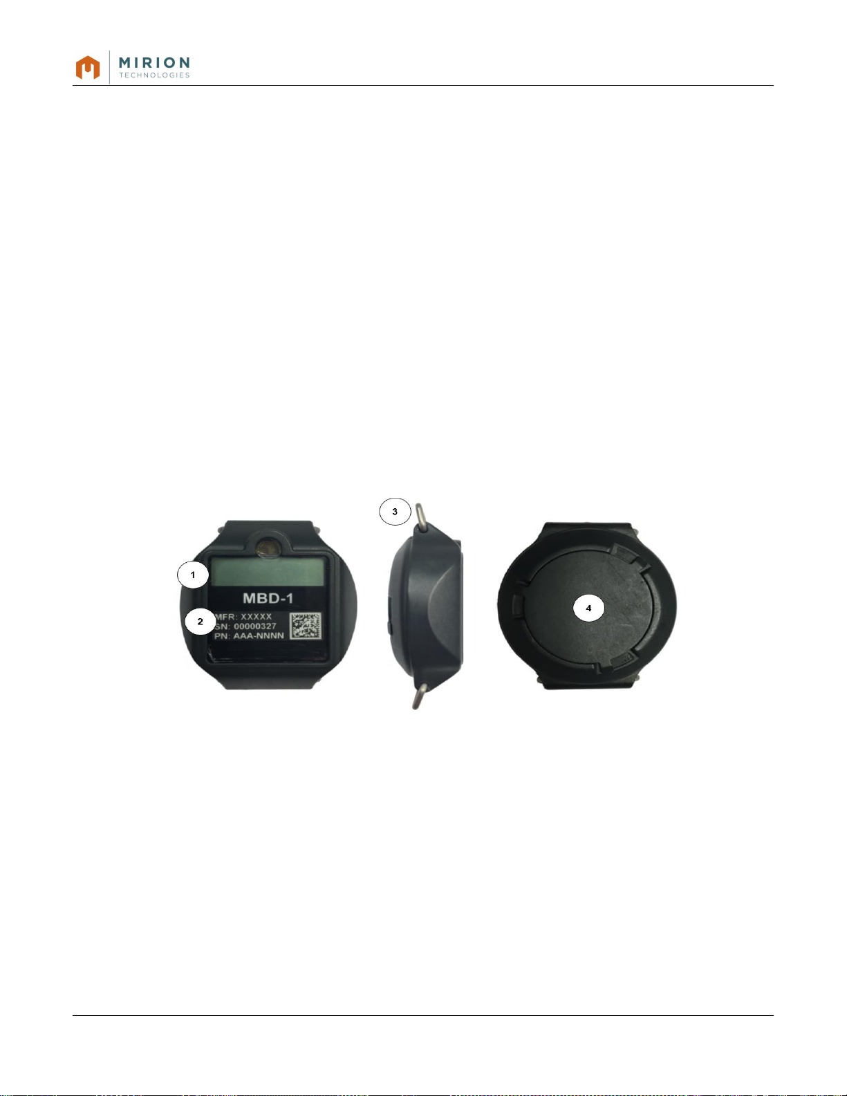
1. LCD Display
3. D-Clip (2) for Wristband
2. Screen Protector and Label
4. Battery Compartment Cover
2. Description
2.1. Physical Description
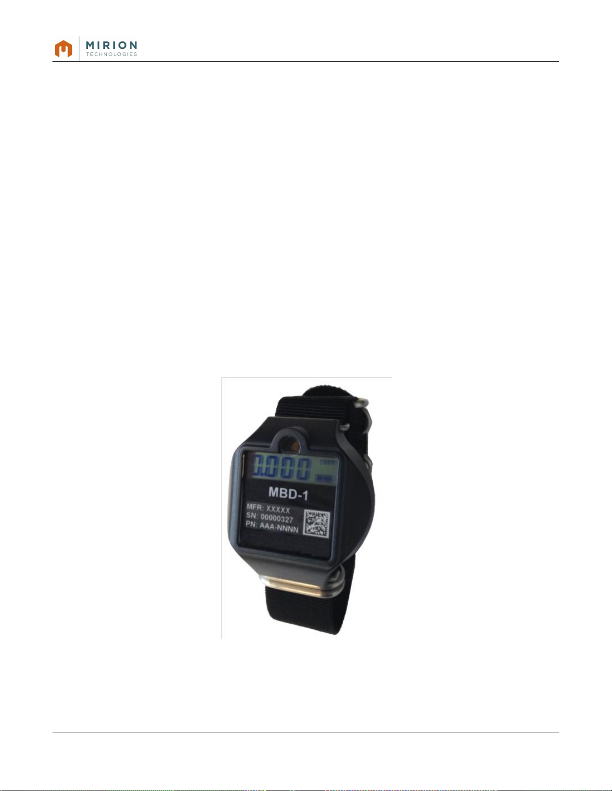
The MBD-1 Battlefield Dosimeter is a wrist worn (like a wrist watch) or chest worn (clipped to lanyard,
pocket, etc.) measurement device providing the wearer real-time radiation exposure data. The MBD-1
features an LCD display, IR and BLE communication, adjustable wristband and/or clip, and field
replaceable battery.
The MBD-1 displays incremental gamma, neutron and beta exposure in configurable display formats
(individual scrolling channels, individual channel or total) and configurable measurement intervals.
Exposure is displayed in units of (m)Rem or (m)Rad. Battery power level is reported using an
interactive symbol found in commercial electronics.
Radiological performance covers the full Hp (10) photon energies and features flat energy response
from 80 KeV to 1.25 MeV range. Recorded data is retained in the MBD-1 in non-volatile memory.
MBD-1 Document No 2096 6832 6
Revision 1.0
Figure 2-1: MBD-1 Physical Features
Page 7
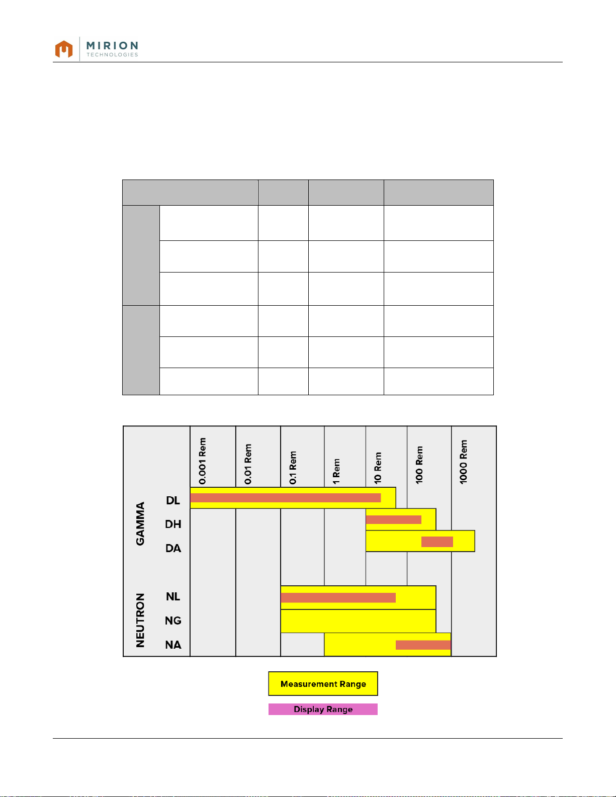
Detector
Code
LLD
Upper Range
Deep - Gamma
DIS Low Range
DL
10 µSv
(1 mrem)
600 mSv
(60 rem)
DIS High Range
DH
1 mSv
(100 mrem)
6 Sv
(600 rem)
MOSFET
DA
10 mSv
(1 rem)
20 Sv
(2000 rem)
Deep – Neutron
ɣ+ n DIS
NL
1.5 mSv
(150 mrem)
6 Sv
(600 rem)
ɣ DIS
NG
1.5 mSv
(150 mrem)
600 rem
(600 mSv)
Pin Diode
NA
10 mGy
(1 rad)
10 Gy
(1,000 rad)
The MBD-1 includes six separate detector elements:
Three (3) elements are provided for gamma measurements,
Three (3) elements are provided for neutron measurements.
Each detector element is listed in Table 2-1, MBD-1 Detector Table and Figure 2-2, MBD-1 Detectors
and Measurement Range Chart below.
Note that while Figure 2-2 lists dose units in rem, any displayed results from the gamma accident range
(DA) or neutron accident range (NA) detector elements are provided in rad.
Table 2-1: MBD-1 Detector Table
MBD-1 Document No 2096 6832 7
Revision 1.0
Figure 2-2: MBD-1 Detectors and Measurement Range Chart
Page 8

Passive,
No Main Battery
Active,
Main Battery installed
IN USE or STORAGE
IN USE
IN STORAGE
Sleep Mode
Dormant Mode
Detectors integrate
dose from radiation
background
(2)
Detectors integrate dose
from radiation
background
(2)
Limited maximum dose to
integrate
(1)
Detectors integrate dose
from radiation
background
(2)
No Display
Real-Time-Clock is Off
Display is On
Real-Time-Clock is On
No Display
Real-Time-Clock is On
No Display
Real-Time-Clock is On
Main Battery approx. 20
days
Main Battery approx. 4
years, completely
discharged
Main Battery approx. 4
years, completely
discharged
Internal battery life
>10 years
Internal battery life
>10 years
Consumes internal battery
(7 years max)
(3)
Internal battery life
>10 years
The MBD-1 provides the user indication of gamma, neutron and beta radiation exposure on its LCD.
This LCD is a four digit, seven-segment display that is easy to see, is not reflective and emits no glow.
A fourth option (d tot) is available that displays the gamma plus neutron dose. Note that up to three
values may be displayed and scrolled. If a single value is selected, the display will blink with the unit
and value, with the exception of ‘d tot’, where the display will stay solid with the total deep dose.
2.2. Power Management & Storage
The MBD-1 is designed for long term storage duration. The device may also be optimized for short term
storage in an “action ready” environment. While possible, storage of the MBD-1 beyond a three year
period is not recommended. A three year service program is recommended to maintain an “operational
ready” condition and ensure optimal performance. End user operational logistics of the MBD-1 typically
determine the storage configuration settings.
MBD-1 can be configured to optimize the battery life of both the primary 3V battery and the internal 6V
batteries while in storage. In addition, the MBD-1 can be configured to limit the detector saturation
potential of the internal detectors while in storage. These mode configurations are implemented using
the MBD reader software.
Table 2.2 describes the power management options for the MBD-1:
(1) Maximum level is about one-third from the element range maximum
(2) Maximum level integrated is the range maximum
(3) Depends on storage /operation temperature
All battery life times are given in normal room temperature conditions.
Elevated temperatures may shorten the battery life time.
When device is active, the IR-wake-up is monitored and can wake the device if needed.
When main battery is completely depleted, the device will continue operating in passive mode.
MBD-1 Document No 2096 6832 8
Revision 1.0
Table 2.2 MBD-1 Power Management Matrix
Page 9

2.2.1. Sleep Mode
The Sleep mode limits detector saturation potential, where the detector voltage is adjusted to limit the
amount of dose that can be stored. The Sleep mode is an effective solution for concerns of detector
saturation resulting from exposure to a nuclear detonation or other high radiation field.
In this state, the microprocessor is programmed to “wake-up” every 2 seconds to search for an IR
communication signal. If discovered, the MBD-1 becomes active for connection to a MAC System, DAK
or DC-1 field reader that is used to configure the dosimeter into an active mode. While in Dormant
mode, the primary battery life is approximately 3 years. However, this mode has negative impact on
the internal battery life, reducing estimated life to 8 years.
MBD-1 dosimeters can be stored without the primary battery installed. As a long term and short term
storage solution, this method maximizes the primary battery life as the only effect on the primary battery
is its self-discharge rate. The MBD-1 detector power is supported by the internal 6 V battery where
there is only a very low draw of current from the detectors, less than 0.3 μA. The combined detector
current draw and the self-discharge account for approximately 1 - 3% power loss per year of life. This
rate is also dependent upon storage temperature (higher temperature, higher-self discharge rate). The
resulting internal battery life is approximately 10 years.
2.2.2. Dormant Mode
The Dormant mode preserves the main battery life by disabling the LCD display and ceasing the
storage of daily dose records. While in Dormant mode, the real time clock is active. In order to “wake”
the MBD-1 from Sleep mode to an active state, an IR device (Reader Dongle or other field device) is
required. In Dormant mode, the Main battery life is approximately 3 years and the internal battery life is
7 years.
MBD-1 Document No 2096 6832 9
Revision 1.0
Page 10

3. Operation
The MBD-1 is designed to be worn with a wristband or strap similar to a watch. Once the
battery is inserted, the MBD-1 is powered on and operates according to its configuration.
There are no pushbuttons, switches, speaker or other annunciation feature.
3.1. Battery
3.1.1. Removal / Replacement
3.1.1.1. Removal
Prior to removing or installing the battery, remove the wristband, if used, to facilitate easier
battery cover removal.
Turn the battery cover counter-clockwise to remove. The battery cover can easily be
removed using a finger to “pull” one of the cover stems counter-clockwise, or by using two
fingers and applying pressure while turning counter clockwise.
Remove the existing battery and dispose in accordance with site requirements.
3.1.1.2. Replacement
Insert a fresh battery into the compartment, positive (+) side facing up, as shown in Figure 32 below.
Verify the presence of the rubber O-ring next along the threading of the cover. If missing or
degraded, replace.
MBD-1 Document No 2096 6832 10
Revision 1.0
Figure 3-1: MBD-1 Battery Cover Removal
Figure 3-2: MBD-1 Battery Cover Installation
Page 11
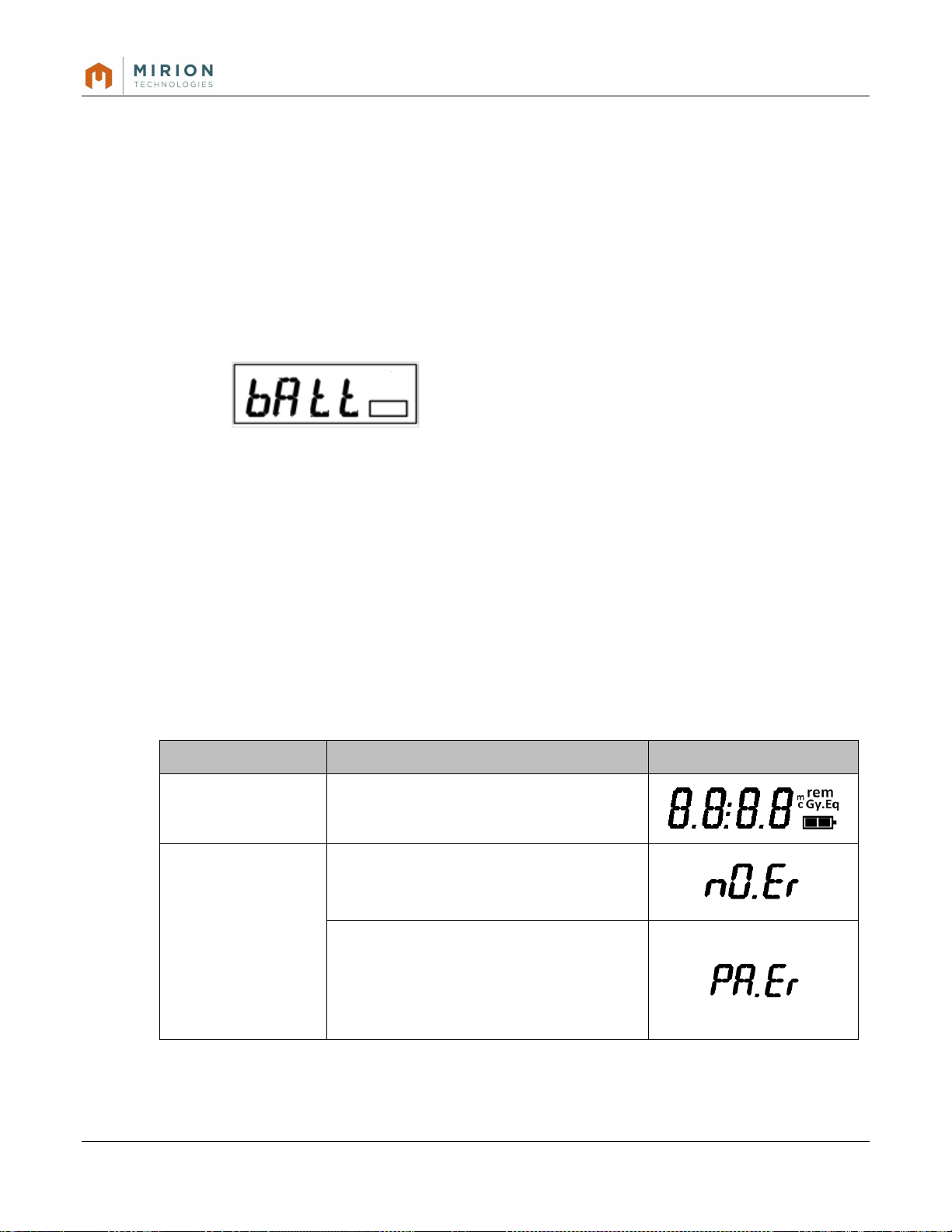
Start-up Routine
Operation with Warning and Effect
LCD Display Indication
LCD Display
Segments
All segments illuminate for 3 seconds,
then 1 second blank
Post Start-up
Following start-up diagnostics, if no
errors have been identified, a nO.Er
message will display
If the MBD-1 becomes operational
following an Error during start-up, the
PA.Er message will appear on the
Display, indicating an Error was
recorded.
Place the battery cover, recessed side down over the compartment, aligning the three stems
in the three slots.
Turn the cover clockwise (to the right) until snug. Using a finger, push a stem until slightly
centered in the slot.
NOTE: The use of a screwdriver or blunt object to tighten or remove the cover is not
recommended. Damage to the MBD-1 may result due to improper technique.
3.1.1.3. Low Battery Indication
When the battery voltage is below 2.6V, a message appears on the display “bAtt” (battery
low).
3.2. Start-up and Diagnostics
3.2.1. Start-up
When the battery is installed, the MBD-1 powers on. There are no switches to power on or
off the MBD-1.
Upon start-up, the MBD-1 performs diagnostics and then becomes active with a live display.
3.2.2. Diagnostics
Table 3-1 below describes the diagnostics routine:
NOTE: The MBD-1 may be stored with or without a battery.
MBD-1 Document No 2096 6832 11
Revision 1.0
Table 3-1: MBD-1 Start-up Diagnostics
Page 12

3.2.3. Operation
The default LCD configuration is designed to display Gamma and Neutron measurement
channels. The display measurement channels can be configured based on end-use
requirements.
The LCD will cycle through two measurement channels over a twenty second period. This
cycle is continuous while the MBD-1 is active. The twenty second interval is the default
value. Other intervals include 40, 60 and 80 seconds.
Figure 3-3: MBD-1 with Active Display
Figure 3-4: MBD-1 Default Display Cycle Timing
A third measurement channel, “d.tot”, is displayed as the Total Deep Dose or, the sum of
the Gamma and Neutron channels. The displayed measurement channels are configurable
using the MBD-1 Service Software. The default display cycle and timing is shown above in
Figure 3-4.
MBD-1 Document No 2096 6832 12
Revision 1.0
Page 13

3.3. Interaction with Data Acquisition Kit (DAK-1)
3.3.1. DAK-1 Description
The DAK is a computer based reader station which can communicate, configure and
transfer recorded data from the MBD-1 dosimeter. The DAK consists of a computer, Reader
Dongle and MBD Reader Software.
The Reader Dongle uses IR and BLE to communicate with the MBD-1. The IR is used to
initiate (wake-up) communication with the MBD-1, then the BLE establishes connectivity with
the MBD for software commands.
NOTE: If the MBD-1 senses no Reader activity for 30 seconds, the MBD-1 will stop
communication in order to preserve battery life. The Reader must re-initiate
communication.
3.3.2. MBD Reader Software Operating Instruction
3.3.2.1. Set-up
o Turn on the computer
o Insert the Reader Dongle into an accessible USB Port.
MBD-1 Document No 2096 6832 13
Revision 1.0
Figure 3-4: Laptop PC with Reader Dongle
NOTE: The Reader Dongle should be positioned in an open area, like on a desktop, so
that the MBD-1(s) can be placed in proximity for communication. If the USB is
inaccessible, or behind a computer, a USB Extension Cord is an effective
solution, as shown in Figure 3-5 below.
Page 14

IR Transmitter
IR Receiver
o Launch the MBD Reader Software
3.3.2.2. Main Window
Figure 3-5: Reader Dongle with USB Extension Cord
MBD-1 Document No 2096 6832 14
Revision 1.0
Figure 3-6: MBD Reader Main window
To wake-up the communication with the MBD-1 Dosimeter, place the MBD-1´s IR Receiver
into proximity of the IR Dongle´s IR transmitter. Thereafter you can start the communication
by clicking the Discover button.
Page 15

3.3.2.3. Dosimeter Data Tab
Figure 3-7: Dosimeter Data Tab
The MBD-1 Dosimeter serial number will be shown in the Dosimeter List window as soon
as the communication link with the Dosimeter has been established and Dosimeter Data
will be read automatically from the Dosimeter
Dosimeter Data:
- MAC Address of the Bluetooth adapter
- Dosimeter’s Serial Number
- User ID, which is stored into the Dosimeter
- Operating Mode selection
o Default, normal operating mode
o Test mode
- Dose Display selection
o Deep Total Dose
o Deep gamma Dose
o Optional Shallow Dose
o Neutron dose
- Recording selection
o Number of unread dose records
o Total amount of dose records
- Display units selection
o Gamma
o Shallow (optional)
o Neutron
MBD-1 Document No 2096 6832 15
Revision 1.0
Page 16

- Display Quantities selection
o cGy
o rem
o cGy Eq
o Automatic
- Auto Assign selection
- Read
o Re-read Dosimeter data
- Write
o Write Dosimeter data
- Assign
o Assign dosimeter to a user
- Re-zero
- View log
o Shows communication log events
3.3.2.4. Download Data Records
Click “Download” button (shown above). The software will ask for a location to save the
information. Choose any location on the computer to initiate the download process. The
process downloads about 80 records per minute. Download until the # of unread records is at
or close to zero.
MBD-1 Document No 2096 6832 16
Revision 1.0
Page 17

3.3.2.5. Reset Tab
Figure 3-8: Reset Tab
Reset Process:
The reset process is achieved by delivering a specific amount of gamma or photon
radiation to the MBD-1. The specific amount of gamma/photon radiation required is
displayed in the Total MBD-1 Dose Box. Once the MBD-1 has been placed in Reset mode
by clicking the Start button, the user will have one (1) hour to complete the reset process.
In the event the required dose cannot be delivered in one (1) hour, multiple Resets will be
required. When the required amount of gamma radiation is delivered, the user needs click
the Stop button to end the Reset process. At the end of one (1) hour, the MBD-1 will
automatically return to normal operation and begin accumulating dose again.
The Reset Process is as follows:
o Place an MBD-1 dosimeter between 4” – 6” from the IR/BLE Dongle (display facing
dongle)
o When the MBD-1 display changes to “Conn”, click the Discover button to start
communication between the MBD-1 and the MBD Reader Software.
o The MBD Reader Dosimeter list will populate the available MBD-1 dosimeter(s)
Note: To reduce the time required for Initialization, the User should download the
Recording History prior to pressing Initialize on the Reset tab. The less unread
history events on the MBD-1, the faster the Initialization process will be.
o Click the Initialize button to begin the process of reading the accumulated dose on
the selected MBD-1
MBD-1 Document No 2096 6832 17
Revision 1.0
Page 18

CAUTION:
Once the Initialize button has been clicked, the user must complete the
Reset Process. Failure to do so, will require a minimum of one (1) hour
before the MBD-1 automatically returns to standard operation
o After the initialization has completed, the MBD-1 total Reset dose will be displayed in the
Total MBD-1 Dose Box, in mrem or rem. The listed dose value is the amount of Reset dose
required to reset the MBD-1 back to a value close to zero. The user shall prepare a
gamma/photon source capable of delivering the specified dose in less than the one hour
time out period
o Click the Start button to place the selected MBD-1 into Reset mode. From this “click” the
MBD-1 will be capable of reset for one (1) hour. The user should complete the reset process
before the one hour time limit expires
Note: During the Reset process, the MBD-1 display will show “in it” until the reset process is
stopped or times out
If the user cannot prepare a gamma/photon source capable of delivering the specified
dose in less than one hour, it will be necessary to repeat the process a number of
times until the Reset is complete. Each successive time, a new Total MBD-1 Dose will
be calculated during the Initialize process on the Reset tab.
o Place the MBD-1 in the gamma/photon field
o After the specific dose is delivered, wake-up the communication again and open the Reset
Tab.
Note: The MBD-1 will remain “discoverable” during the entire Reset process and will not
require the IR/BLE Dongle to “wake” the MBD-1 prior to populating in the MBD
Reader Dosimeter List. If the one (1) hour time limit is exceeded, the MBD-1 will no
longer be “discoverable”.
o On the Reset tab, click the Stop button
Note: If the Reset Process is not complete and a sufficient amount of gamma/photon dose
is not delivered to the MBD-1, a warning will appear with the statement “The
remaining dose is high, repeat the reset procedure”.
o In the MBD Reader software, click on the Dosimeter data tab
MBD-1 Document No 2096 6832 18
Revision 1.0
Page 19
o Click the Assign tab to assign the MBD-1 and re-zero the display
o The MBD-1 will display “in it” for about two (2) minutes, after which time the MBD-1 is ready
for use
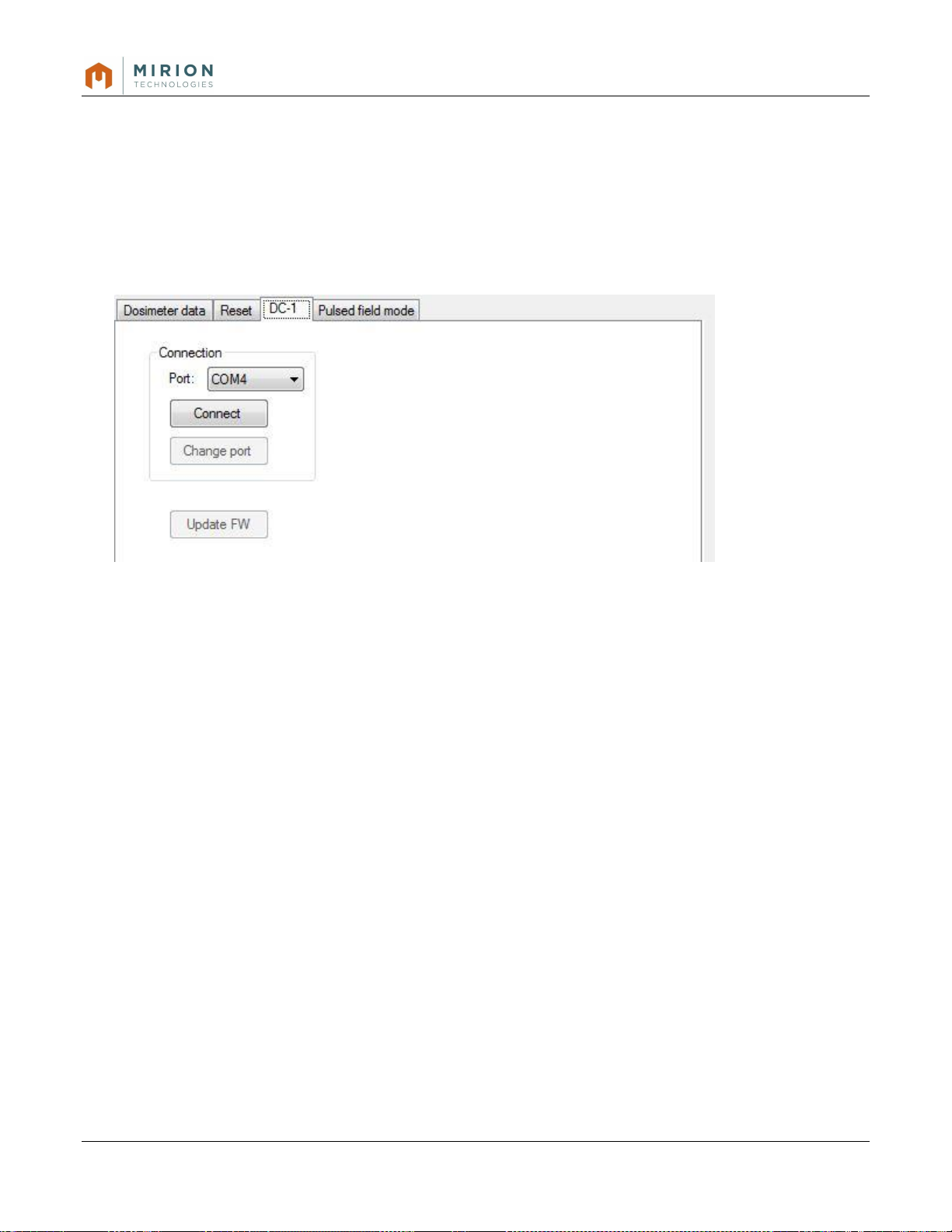
3.3.2.6. DC-1 Tab
Here you can connect into an optional external Data Collector Device.
Figure 3-9: DC-1 Tab
MBD-1 Document No 2096 6832 19
Revision 1.0
Page 20

3.3.2.7. Pulsed Field Mode Tab
Figure 3-10: Pulsed Field Mode Tab
Here you can activate the Pulsed Field Mode for a specific dose element.
MBD-1 Document No 2096 6832 20
Revision 1.0
Page 21
Detector
Type
Designation
Range
DIS Low Range
Deep Gamma
DL
10 µSv to 600 mSv (1 mrem to 60 rem)
DIS High Range
Deep Gamma
DH
1 mSv to 6 Sv (100 mrem to 600 rem)
MOSFET
Deep Gamma
DA
10 mSv to 20 Sv (1 rem to 2000 rem)
DIS n
Deep Neutron
NL
1500 µSv to 600 mSv (150 mrem to 60 rem)
DIS
Deep Neutron
NG
1,5 mSv to 6 Sv (150 mrem to 600 rem)
Pin Diode
Deep Neutron
NA
10 mGy to 10 Gy (1 rad to 1000 rad)
Energy Range:
80 keV – 2 MeV
Dimensions:
(LxWxH) 53 x 56 x 22 mm (2.08 x 2.2 x 0.86 inches)
Weight:
48 g (1.7 oz) with battery
Operating Temperature range:
-20°C to +50°C (-4°F to 122°F)
Storage Temperature range:
-40°C to +70°C (-40°F to 158°F)
Humidity:
Up to 95 % relative humidity
Water Resistance:
-20°C to +50°C (-4°F to 122°F)
Drop Test:
1 m height on hard wood surface in case
RF-RI-EMI Emission:
RS101, RS02, RS103, RE102 compliant
Sand/Dust, Salt Fog & Fungus:
Compliant IAW MIL-STD 810G
Main Battery (Field Replaceable):
Renata CR2430, 3 V, lithium coin cell
Autonomy:
700 hours
Internal (non-replaceable):
Renata CR1216MFR, 6 V, lithium coin cell
Autonomy:
>10 years
4. Technical Specifications
4.1. Radiological
4.2. Physical Characteristics
4.3. Environmental Characteristics
4.4. Electrical Characteristics
MBD-1 Document No 2096 6832 21
Revision 1.0
 Loading...