

Page 1
Featuring:
radiation monitoring
systems
A Mirion Technologies Division
DAK 250
Neutron Flux Instrumentation
DAK 250
Digital Start-up Channel
The DAK 250 digital start-up range channel forms
part of the proTK™ product line. It has been designed
for neutron ux monitoring in the pulse and inter-
mediate range in combination with pulse detectors,
e.g. BF3-counters and neutron ionization chambers.
Hardware and software of the DAK 250 are designed
and quali ed for applications at the level of the reac-
tor protection system.
APPLICATIONS
• Operational process monitoring
○ Safety related signal processing for neutron ux
monitoring in the pulse range (DAK 250-i) and
intermediate range (DAK 250-g)
RELATED PRODUCTS
• Neutron detectors: e.g. BF3-counters and
ionization chambers KNK/KNU 50
• Digital signal processing channels: e.g. for wide
range or power range monitoring
FEATURES
● Signal ltering with adaptive time constant
● Calibration to neutron ux signal (nv, P/Pn)
● Calculation of the ux change rate (reciprocal of the
reactor period)
● Generation of analog and binary signals for the reactor
protection system
● Linear and/or logarithmic analog outputs
● Remote test signal generators
● Optional: calculation of the reactor reactivity
Page 2
Since norms, speci cations and designs are subject to occasional change, please ask for con rmation of the information given in this publication.
Mirion Technologies (MGPI) SA
Route d’Eyguières
FR-13113 Lamanon
France
T +33 (0) 4 90 59 59 59
F +33 (0) 4 90 59 55 18
Mirion Technologies (MGPI) Inc
5000 Highlands Parkway
Suite 150
Smyrna, GA 30082
USA
T +1 770 432 2744
F +1 770 432 9179
Mirion Technologies (MGPI H&B) GmbH
Landsberger Strasse 328a
DE-80687 Munich
Germany
T +49 (0) 89515 13-0
F +49 (0) 89515 13 169
Mirion Commercial (Beijing) Co., Ltd.
Shanghai Jiangchang Commercial Branch
Room 801, 78 Jiangchang SanLu
Zhabei District, Shanghai 200436
PR of China
T +86 21 6180 6920
F +86 21 6180 6924
DAK 250
Neutron Flux Instrumentation
www.mirion.com
144966EN-C
DETECTORS AND PREAMPLIFIERS
● Pulse detectors for DAK 250-i:
○ BF3- or He3-counter tubes
○ B10-proportional counters
○ Fission chambers in pulse mode
● Pulse preamplifi er NV 320:
○ Input and output impedance matched to the
impedance of the cables
○ Remote pulse generator for testing
● Ionisation chambers for DAK 250-g: compensated or
non-compensated
● Current-to-frequency-converter NV 102H: 10 decades
of measuring range
● Detector supply 0 ... 0.5/1/2/4 kV located in the
central electronic unit
DIGITAL SIGNAL PROCESSING
● 80C31/32 multi-processor system
● Program memory: EPROM
● Parameter memory: CMOS-RAM with integrated
Li-battery
● Data interface: RS 232 and/or RS 485
● Internal LC-display: 2 x 16 characters
OUTPUT SIGNALS
● Linear and/or logarithmic count rate or neutron ux
● Neutron ux change rate = 1 / reactor period to be
con gured, e.g. -1.25 ... 0 ... 12.5 %/s corresponding
to -80 ... ∞ ... +8 s reactor period
● Analog outputs: 0/4 ... 20mA/600 Ω, insulated
● Binary outputs: insulated relay change overs,
60V/0.5A or 125V/1A
● Optional: reactimeter on a single additional interface
board NK 21
OTHER CHARACTERISTICS
● DC power supply: 18 ... 33 VDC, approx. 1.6A at 24 V
● Optional: AC power supply: 230 VAC or 115 VAC
+10%/-15%, approx. 40 VA
● Operating temperature: 0 ... 70°C (32 ... 158°F)
for the main electronics
● Mechanical vibrations: < 5 g, 5 ... 100 Hz
● 19” modular system according to IEC 60297
● Rack size (W×H×D): 483 mm × 133 mm × 280 mm
(19 in x 5.2 in x 11 in)
● Plug-in boards: 100 mm × 160 mm (3.9 in x 6.3 in)
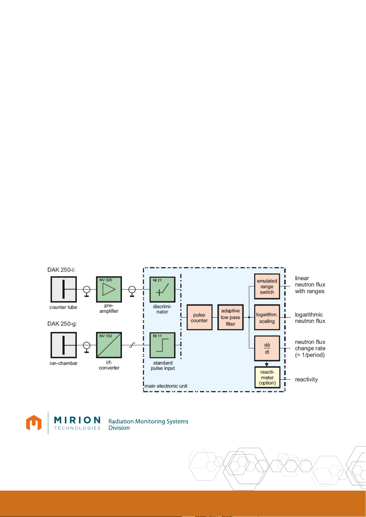
DAK 250
Schematic diagram
 Loading...