

Page 1

No.:
1986RM2
Version
180214
System / Product:
MIREL RM2 Integrated On-Board System
Title:
Operating Manual
Further source- and enclosed files:
File Description
1
2
3
List of document versions:
Version
150701 Document introduction Ing. Csáder Ing. Michalec Ing. Michalec
160530 Extension of system indication Ing. Michalec Ing. Michalec Ing. Michalec
160928 Extension for safety, operational and system functions Ing. Mandrik Ing. Jasenčák Ing. Michalec
161109 Extension for accord check of movement direction, vigilance
confirmation with drive controllers, issue of line pulses
180214 Extension of procedure in case of accident Ing. Jasenčák Ing. Jasenčák Ing. Michalec
Description Compiled by Validated by Approved by
Ing. Jasenčák Ing. Jasenčák Ing. Michalec
Pages /
Connection
1986RM2 : 180214 1
Page 2

Contents
1 Intended Use of the Document ...........................................................................................................4
2 Specification of Document Changes ...................................................................................................5
3 Applied Marking and Terminology ......................................................................................................6
4 General Characteristics ......................................................................................................................7
5 Set of System Units ............................................................................................................................8
5.1 Central Unit ......................................................................................................................................................9
5.2 Indication Unit ................................................................................................................................................ 11
5.3 Identification Unit ........................................................................................................................................... 12
6 Putting into Operation and Termination of Operation ....................................................................... 14
7 Driver Cab Activation ........................................................................................................................ 17
8 Login, Navigation in Menu and Logoff .............................................................................................. 18
9 Selection of System Operating Mode ............................................................................................... 21
9.1 SHUNTING OPERATING MODE ................................................................................................................... 22
9.2 OPERATION Operating Mode ....................................................................................................................... 22
9.3 WORK Operating Mode ................................................................................................................................. 23
9.4 DEAD-IN-TOW Operating Mode .................................................................................................................... 24
10 Overview of System Functions ......................................................................................................... 25
11 Safety Operation Functions .............................................................................................................. 27
11.1 Odometry ....................................................................................................................................................... 27
11.2 Movement Speed Indication ........................................................................................................................... 27
11.3 Vigilance Supervision ..................................................................................................................................... 27
11.4 Cyclical Vigilance Supervision ....................................................................................................................... 28
11.5 Increased Cyclical Vigilance Supervision ....................................................................................................... 28
11.6 One-Time Vigilance Check after Setting DRV into Motion .............................................................................. 29
11.7 Maximum Design Speed Supervision ............................................................................................................. 29
11.8 Supervision of Maximum Speed for Operating Mode ..................................................................................... 29
11.9 Operational System Intervention .................................................................................................................... 30
11.10 Control of Safety Outputs ............................................................................................................................... 31
11.11 Provision of Safety-Relevant Data to Communication Interface ...................................................................... 32
12 Operational Functions ...................................................................................................................... 33
12.1 Indication of Maximum Permitted Speed ........................................................................................................ 33
12.2 Indication of Preset Speed ............................................................................................................................. 33
12.3 Data Collection from Technology Interface ..................................................................................................... 33
12.4 Data Collection from Communication Interface .............................................................................................. 33
12.5 Registration of Operational and System Data ................................................................................................ 33
12.6 Communication via GSM Gateway ................................................................................................................ 34
12.7 Control of Technological Binary Outputs ........................................................................................................ 34
12.8 Data Provision to Communication Interface ................................................................................................... 34
12.9 GPS Localization ........................................................................................................................................... 37
12.10 Remote Train Stop ......................................................................................................................................... 37
12.11 Check of Accord Between Actual and Preset Direction .................................................................................. 37
13 System Functions ............................................................................................................................. 39
13.1 Clock Synchronization ................................................................................................................................... 39
13.2 System Start-Up ............................................................................................................................................ 39
13.3 Selection of Active Driver´s Cab ..................................................................................................................... 39
13.4 Operation Mode Setting ................................................................................................................................. 39
1986RM2 : 180214 2
Page 3

13.5 Audible Indication .......................................................................................................................................... 39
13.6 Visual Indication............................................................................................................................................. 40
13.7 Regulation of Indicator Brightness ................................................................................................................. 41
13.8 Termination of System Operation ................................................................................................................... 41
13.9 Error Detection and System Intervention ........................................................................................................ 41
13.10 One-Time Diagnostic Test D1 ........................................................................................................................ 43
13.11 Repeated Daily Diagnostic Test D1 ............................................................................................................... 43
13.12 Continuous Diagnostic Test D2 ...................................................................................................................... 43
13.13 Functional Test D3 ......................................................................................................................................... 43
14 Procedure in case of accident .......................................................................................................... 44
15 Notes ................................................................................................................................................ 45
1986RM2 : 180214 3
Page 4

1 Intended Use of the Document
The document specifies operation method and conditions of Integrated On-Board system MIREL
RM2.
The document follows up and refers to documentation stated below:
No. Version Title
[1] 1976RM2 180214 Technical Conditions
[2] 1984RM2 150701 Technical Report
[3] 1987RM2 180620
[4] 1988RM2 180214 RM2 System Catalogue Sheet
[5] 1985RM2 180410 Specification of Configurations
[6] 2170RM2 180813 Specification of Registered Data Configuration
[7] 1992RM2 180214 Installation Manual
Document is intended for employees of:
n
Producer, who are trained and authorized to perform diagnostics and service of MIREL RM2
Integrated On-Board System
n
Operator, who are trained for operation or diagnostics and maintenance of MIREL RM2 Integrated OnBoard System and have authorization for this activity from responsible representative of the Operator
n
Third parties, acting in DRV production and reconstruction, who are trained and authorized to perform
diagnostics and service of MIREL RM2 Integrated On-Board System and have the authorization for
this activities from their superior
This document doesn´t replace operating directive of the User for the use of MIREL RM2 Integrated OnBoard System. During creation of operating rules, it is necessary to ensure compliance with the relevant
standards.
Maintenance Manual, Diagnostics
1986RM2 : 180214 4
Page 5

2 Specification of Document Changes
Version 180214
Extension of document about the process of reading registered data in case of accident. Update of chapter
Error detection and system intervention, removal of error code tables, replacement with the reference to
the document Instructions for maintenance and diagnostics. Updating values for control Vmax for values
3/5/7 km/h. Add a description of automatic logging in for operator.
Version 161109
Updates in specification of D1 diagnostic test, cooperating devices, audible indication, register of errors
and emergency stop indications. Extension with check of accord between DRV movement direction with
adjustment of direction controllers, vigilance confirmation with drive controllers, extension with functionality
of track pulse issue. Extension of indication on ZJ modules.
Version 160928
Extension of document with safety, operating and system functions.
Version 160530
Extension of system indication on indication and identification unit.
Version 150701
Document introduction.
1986RM2 : 180214 5
Page 6

¿
3 Applied Marking and Terminology
Active (driver) cab Cab of the railway vehicle with the control switch turned on and a present driver
EPV Electropneumatic valve
Functional property „B“
Functional property „G“
Functional property „L“
Functional property „M“
Functional property „R“
Functional property „S“
GGAM Internal module in central unit with GPS and GSM modules
DRV Driving rail vehicle, including train sets, steering rail vehicles, work machines
IEC International Electrotechnical Commission
Installation
documentation,
application
documentation
IRC Incremental sensor of axle rotation on rail vehicle
LSM Device cooperating with GPS module
Functional property control of vigilance
Functional property GSM gate
Functional property localization (place, time)
Functional property measurement and speed indication
Functional property registration of data
Functional property registration in terms of EN62625-1
and similar vehicles
Documentation compiled for application of Integrated On-Board System MIREL
RM2 for specific type of railway vehicle, as a rule it comprises wiring diagram,
assembly procedure, activation and configuration procedure, as well as
component layout on DRV
LCM Device cooperating with GPS and GSM modules
Maximum design speed Maximum speed as stated by railway vehicle producer or speed specified as
maximum one after a reconstruction
Maximum speed of
operating mode
RM2ZJ Central unit of MIREL RM2 system
RM2IN Indication unit of MIREL RM2 system
RM2ID Identification unit of MIREL RM2 system
SNUM MIREL RM2 System No.
ST1 Engine driver cab 1
ST2 Engine driver cab 2
TST1 Technology post 1
TST2 Technology post 2
UIC Union Internationale des Chemins de fer – International Union of Railways
Maximum speed specified for the operating mode, in which the on-board
system has been switched
Command pushbutton
1986RM2 : 180214 6
Page 7

4 General Characteristics
The MIREL RM2 Integrated On-Board System integrates the function of DRV speedometer, on-board
recording device, as well as protection device of vigilance monitoring. Basic functions are measurement of
actual rolling stock driving speed, measurement of covered distance, evaluation of movement direction,
calculation and indication of movement speed at driver cabs as well as record generation of mentioned
quantities. Beyond mentioned quantities, the system carries out a record of actual values for other safetyrelated, operating and technology quantities from DRV, dependent on independent time- and distance
scale in real time, in extent based on system configuration and installation method applied for a given type
of rail vehicle. The system provides safety-relevant as well as safety-irrelevant output signals, dependent
on measured actual speed and covered distance of the rail vehicle.
The MIREL RM2 Integrated On-Board System carries out the driver or DRV operating staff vigilance
supervision, in compliance with specification of a national train protection system of Class B, type LS or
eventually in compliance with specification of vigilance supervision pursuant to UIC 641.
The MIREL RM2 Integrated On-Board System fulfils the function of operating and technology data transfer
via the GSM gateway to a remote server. Apart from that, the system provides for determination and
registration of DRV position and for time synchronization based on GPS signal.
The actual extent of MIREL RM2 Integrated On-Board System functional properties is determined by
system configuration for specific type application case.
The MIREL RM2 Integrated On-Board System can be operated on rail vehicles of all types of traction, on
steering rail vehicles, work machines and similar vehicles.
Power supply of MIREL RM2 Integrated On-Board System is provided from rail vehicle battery source.
The specific system modification is chosen based on voltage of the vehicle battery source. Operation and
control of the MIREL RM2 Integrated On-Board System is carried out solely from driver´s cab.
The MIREL RM2 Integrated On-Board System is an electronical numeric system designed based on
modules of 3rd MIREL system generation. System has been designed as an open one, consisting of a
secure core and application-variable extension modules. The application variability of extension modules
and cooperating devices allows apart from integration with third parties systems also data transfer from
DRV to central databank by means of GSM technology, as well as clock synchronization and localization
with use of GPS technology.
System has been conceived as a secure system with SIL4 safety integrity level for dedicated safetyrelevant functions. The required safety level is achieved by means of architecture with secure core of
central unit, grouping of special watchdog circuits, double-channel(quadruple-signal) measurement of
speed and covered distance. In case of system modification with functional property “R” and secure
system with SIL 4 is ZJ equipped with duplicated recording medium. In case of neediness completion of
requirements of terms EN62625 the ZJ is equipped with functional property “S” and another recording
medium which must accomplish with requirements of this term.
The MIREL RM2 Integrated On-Board System performs a one-time as well as continuous self-diagnostics
and enables to carry out functional test for testing of proper function of system components and important
cooperating devices. Apart from periodic execution of D3 functional test and periodical execution of D4
prophylactic inspection, the system is maintenance-free.
1986RM2 : 180214 7
Page 8
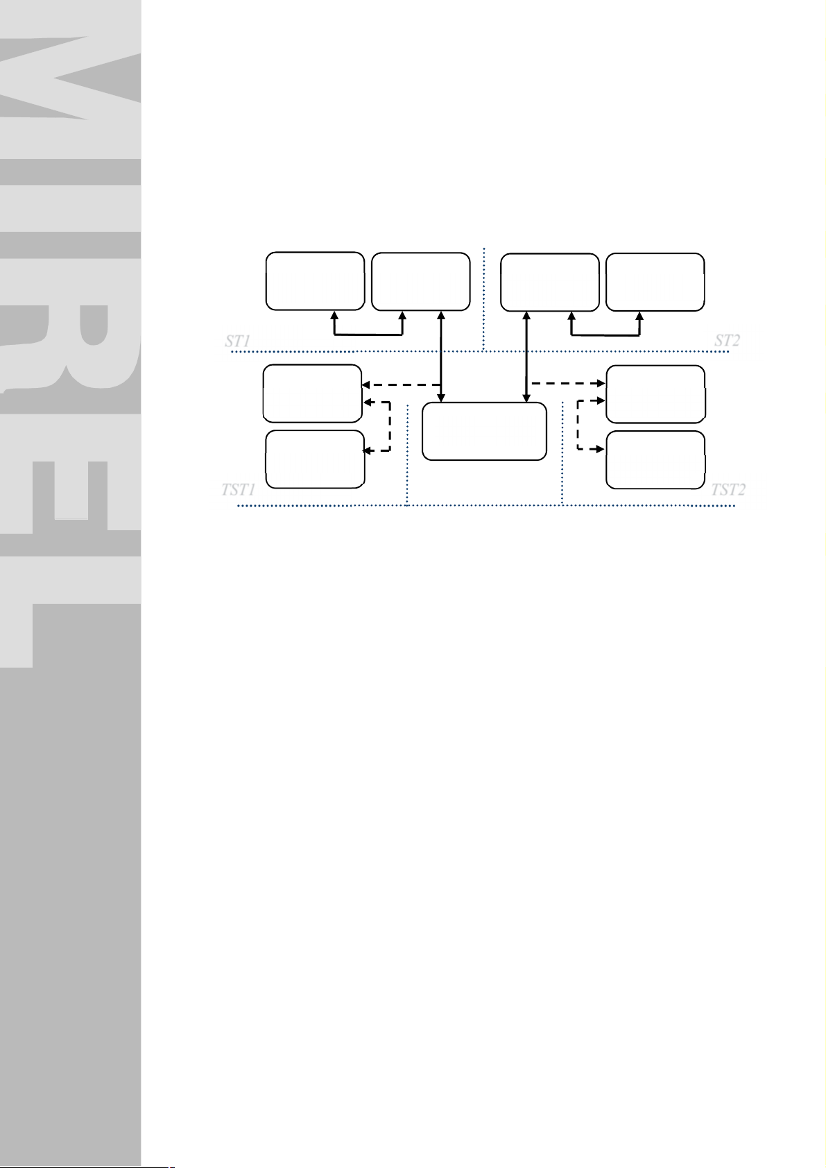
5 Set of System Units
The MIREL RM2 Integrated On-Board System contains in its complete set-up following devices:
n
Central unit ZJ 1
n
Indication unit IN max 4
n
Identification unit ID max 4
IN1
ID1
ID2
IN2
ST1
IN3
ZJ
ID3
IN4
ID4
TST1 TST2
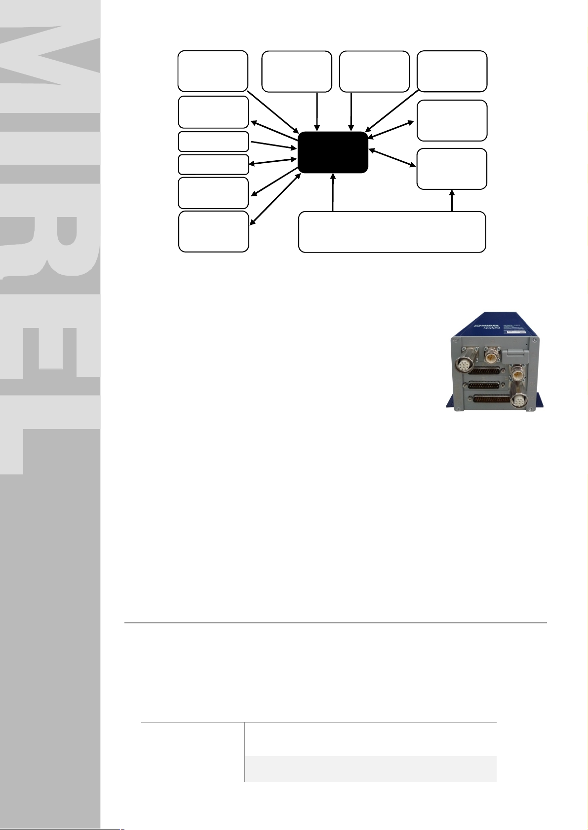
It can cooperate with following functional units:
n
Incremental axle speed sensor 1x
n
Control switches at cabs 2x
n
Drive controllers 2x
n
Direction controllers 2x
n
Mode selectors at cabs 2x
n
EPV electropneumatic valve 1x
n
Pressure switch 1x
n
Pressure sensor 2x
n
Technological secure relay 3x
n
Communication gateway MIREL LCM/ synchronization and localization gateway MIREL LSM
1x
n
Extension devices MIREL EXIO 4x
n
Cooperating systems
ST2
1986RM2 : 180214 8
Page 9
Axle speed
sensor
EPV
Pressure switch
Pressure sensor
Secure relay
Cooperating
systems
Control switches
MIREL RM2
Mode selectors
Registered binary and analogue signals
Vigilance buttons
Drive, direction
controllers
MIREL LCM/
MIREL LSM
MIREL EXIO
5.1 Central Unit
Central unit provides main operating safe and operational functions of the MIREL RM2 Integrated OnBoard System:
n
Speed measurement
n
Calculation and saving of covered distance
n
Evaluation of movement direction
n
Driver vigilance supervision
n
Maximum speed supervision
n
Supervision of DRV movement direction
n
Operational system intervention
n
Data collection and registration
n
Communication with connected cooperating devices of DRV
n
Sensing of binary and analogue input signals
n
Control of technological binary outputs
n
Data provision to system communication interface
n
System clock localization and synchronization (in case of modification with GGAM module or
cooperating element LSM/LCM)
n
Data transfer via GSM technology (in case of modification with GGAM module or cooperating
element LCM)
n
Wheel flange lubrication
n
Issue of line pulses
The central unit has been designed as a modular system. It can be built inside of the structural system in
compliance with standard IEC 297, i.e. basic width of 19”. For systems without application need of larger
number of internal extension modules it is possible to apply the central unit in version of a compact TUG
structural system.
Indication elements on central unit´s front panel
n
Double-colour indicator OIZJ1 on module ZJ-A
n
Double-colour indicator OIZJ2 on module ZJ-B
n
Double-colour indicator OIZJ3 on module ZJ-C
n
Other double-colour indicators of individual extension modules
Module status Colour Indication Period S class
Active diagnostic of
functional module
Internal error of
functional module
1986RM2 : 180214 9
red/blue/violet flashing 1,5 s
red flashing 300 ms
33 % (red)
33 % (blue)
33 % (violet)
33 % (red)
67 % (exting.)
Page 10

Serious fault of
functional system
Communication error
of functional module /
light fault of functional
system
Start-up red lighting - Start-up
accomplishment
Functional module
operation with own
power supply)
Functional module
operation without own
power supply)
red/blue flashing 1 s
red/blue flashing 1 s
blue lighting - -
blue flashing 1 s
extinguished - - -
50 % (blue)
50 % (red)
33 % (red)
67 % (blue)
50 % (blue)
50 % (exting.)
1986RM2 : 180214 10
Page 11
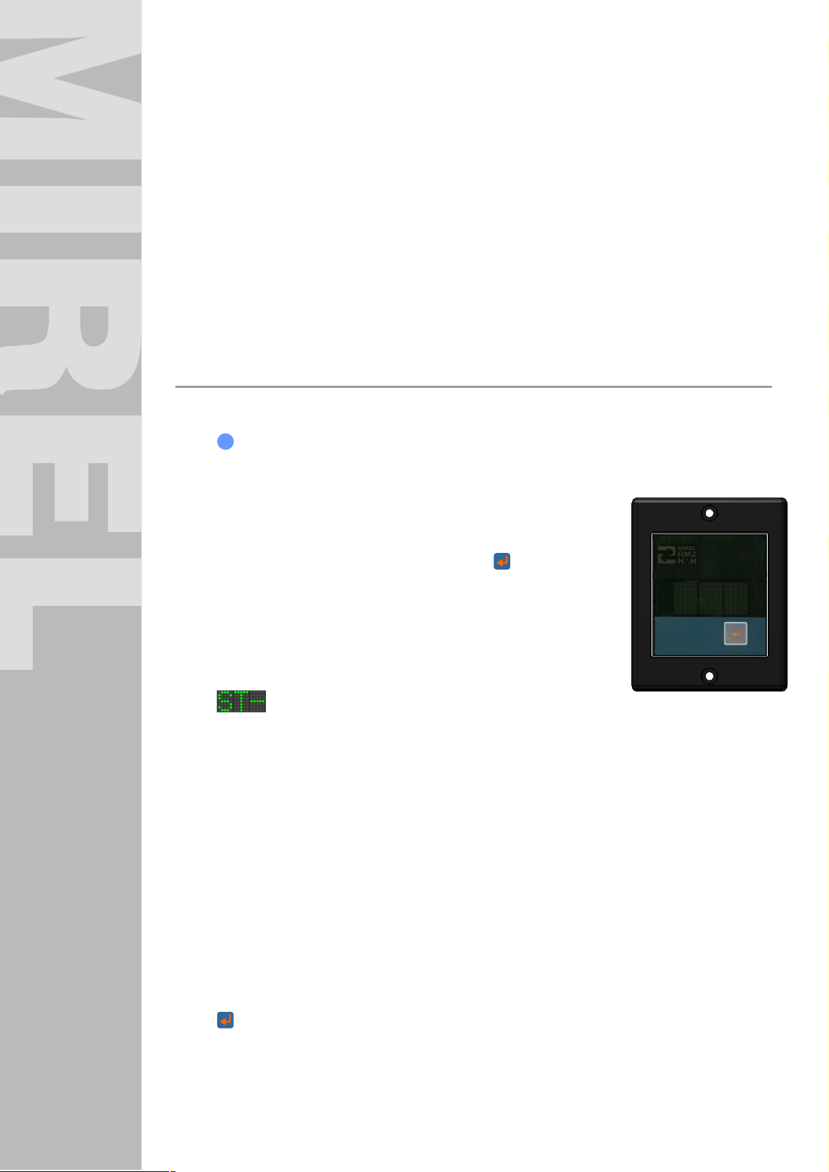
5.2 Indication Unit
Indication unit provides for visualization of following operation data at driver´s cab:
n
Movement speed (dial indicator, digital indicator, graphic display, or their combination)
n
Maximum permitted speed – red light trace (only RM2IN.1, RM2IN.2)
n
Preset speed – green light trace (only RM2IN.1, RM2IN.2)
n
System error indication
n
System indication intervention
n
Vigilance confirmation indication (only RM2IN.S, RM2IN.2)
In case of system configuration with vigilance supervision functionality a numerical indication unit RM2IN.S
must be installed, equipped with command pushbutton and indicator of vigilance prompting/confirmation or
RM2IN.2 respectively. The unit indicated violation of maximum speed by flashing of numerically displayed
travel speed on display. Indication unit RM2IN.S doesn´t indicate the maximum and preset speed. With
version of analogue indication unit RM2IN.1, the maximum and preset speed is indicated by red and green
light trace, movement speed is indicated numerically on display and simultaneously by dial indicator on
analogue scale. All versions of indication units have a function of brightness regulation.
Indication and control elements on front panel of numeric indication unit RM2IN.S
n
indicator OIIN1:
· permanent lighting indicates condition which doesn´t require vigilance confirmation by driver
n
NZ indicator OIIN3:
· flashing indicates emergency stop, i.e. operational system
intervention, in time, when the intervention can´t be terminated
· permanent lighting indicates operational system intervention, which
can be terminated by command pushbutton or re-initializing of
MIREL RM2 Integrated On-Board System.
n
S indicator OIIN4:
· flashing indicates serious system error and error of system safety
functions
n
ERR indicator OIIN5:
· permanent lighting indicates a light system error
n
· permanent lighting indicates DRV travel speed
· indicates status of inactive cab
· indicates reason of DRV emergency stop
· indicates request for execution and execution status of diagnostic test D1
· indicates status of activated diagnostic test D3
· indicates preset operating mode of MIREL RM2 Integrated On-Board System
· flashing indicates DRV travel speed at:
n
triple-character alphanumeric indicator OIIN6:
· meeting of conditions leading to emergency stop
· failed confirmation of request to confirm DRV staff vigilance
· violation of DRV maximum speed
· discrepancy between DRV movement and setting of direction controllers
· DRV movement prior to D1 accomplishment
· Serious system error
· DRV movement without staff login in all operating modes of MIREL RM2 Integrated On-
Board System, with exception of SHUNTING mode
pushbutton of command OIIN7
1986RM2 : 180214 11
Page 12
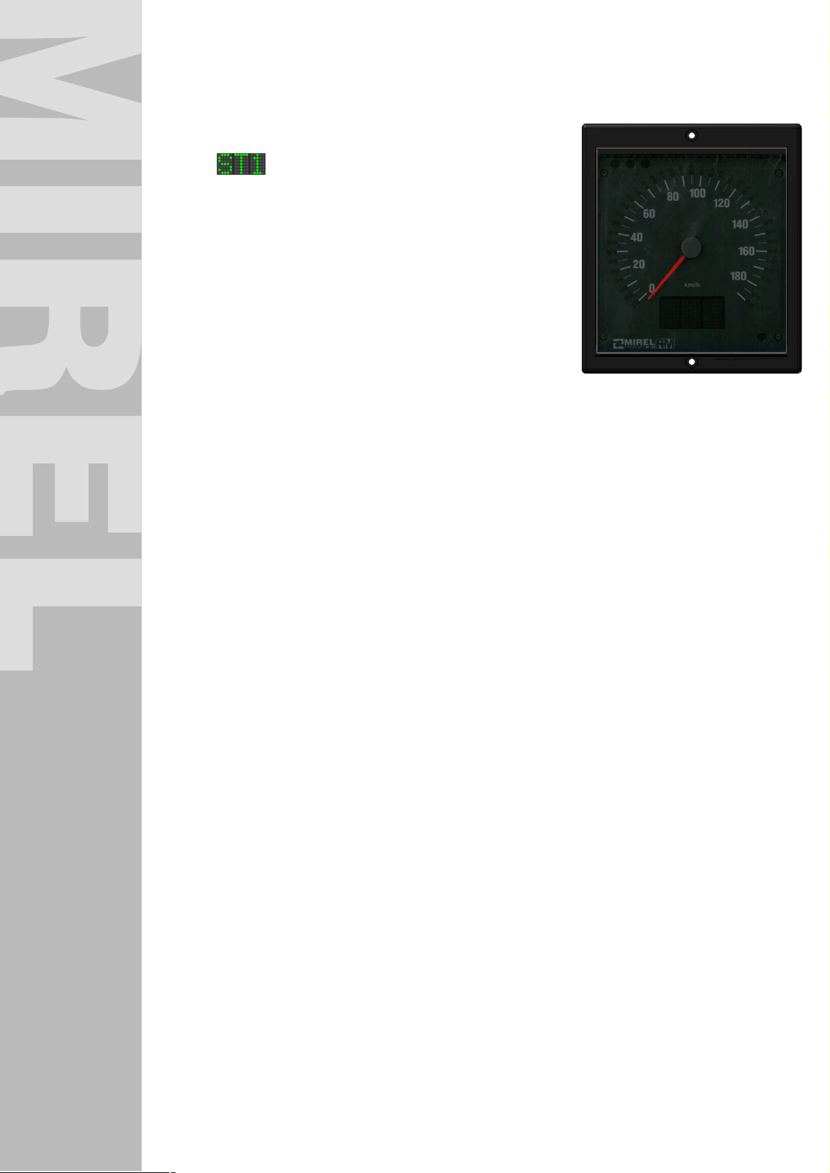
Indication and control elements on front panel of analogue indication unit RM2IN.1
n
S indicator OIIN4:
· Flashing indicates a serious system error and fault of system safety functions
n
ERR indicator OIIN5:
· permanent lighting indicates a light system error
n
· permanent lighting indicates DRV travel speed
· indicates status of inactive cab
· indicates status of DRV emergency stop
· indicates execution status of diagnostic test D1
· indicates status of activated diagnostic test D3
· indicates preset operating mode of MIREL RM2 Integrated
· flashing indicates DRV travel speed at:
n
Red light trace OIIN8:
· Indicates maximum permitted speed
n
green light trace OIIN9:
· indicates preset speed
n
dial indicator OIIN10:
· indicates DRV travel speed
triple-character alphanumeric indicator OIIN6:
On-Board System
· meeting of conditions leading to emergency stop
· failed confirmation of request to confirm DRV staff
vigilance
· violation of DRV maximum speed
· discrepancy between DRV movement and setting of direction controllers
· DRV movement prior to D1 accomplishment
· Serious system error
· DRV movement without staff login in all operating modes of MIREL RM2 Integrated On-
Board System, with exception of SHUNTING mode
5.3 Identification Unit
Identification data of engine driver, driving railway vehicle and train are entered by identification unit.
Simultaneously, the identification unit provides for a more detailed indication of operation data than
indication unit. Driver´s ID, train ID, forwarder ID, operating mode of driving vehicle, train weight and length
are entered. Vehicle movement speed, maximum speed, preset speed, total covered distance, user´s
covered distance, distance covered since system start, date and time, set wheel flange diameter, system
number, system errors are indicated and in case of localization module, the actual geographical DRV
position as well. On the introductory identification unit screen of MIREL RM2 Integrated On-Board System,
the DRV staff has the option to select device language for communication. By repeated pushing the ESC
pushbutton on indication unit, the language version is sequentially changed. Slovak, Polish and Hungarian
languages are available. After repeated system start-up, the language option, which has been active
before switching off the MIREL RM2 Integrated On-Board System shall automatically be activated. The
identification unit is equipped with a 12-pushbutton keyboard for navigation in menu and for entering of
data. Brightness intensity of display and indication LEDs is regulated automatically dependent on external
illumination intensity.
1986RM2 : 180214 12
Page 13

Indication and control elements on front panel of identification unit
n
S indicator OIID2:
· flashing indicates a serious system error and fault of system
safety functions
n
ERR indicator OIID3:
· permanent lighting indicates a light system error
n
double-line fluorescence display OIID4:
· ensures interaction with staff when entering/display of login,
operational and diagnostic information
n
numeric keyboard OIID5:
· provides for navigation within main menu and individual submenus of identification unit
· provides for operating mode of MIREL RM2 Integrated On-Board System
· provides for command issue for zeroing of daily and user distance, command for error reset and
input commands
· comprises following pushbuttons with navigation meaning
· pushbutton 2 – movement upwards (thereinafter as ↑)
· pushbutton 4 – movement to the left (thereinafter as ←)
· pushbutton 6 – movement to the right (thereinafter as →)
· pushbutton 8 – movement downwards (thereinafter as ↓)
· pushbutton ESC – return
· pushbutton ¿– command pushbutton
The identification unit serves for entering of identification data by the driver and provision of alphanumeric
information on display. Apart from login dialogue, following items can be displayed on identification unit:
n
calendar date and time – numeric value [h, min, s]
n
time until repeated diagnostic check D1
n
motohours
n
total covered distance of DRV – numeric value [km]
n
distance covered since system start – numeric value [km]
n
user´s covered distance – numeric datum [km]
n
movement speed – numeric value [km/h]
n
maximum speed – numeric value [km/h]
n
preset speed – numeric value [km/h]
n
geographical position DRV [geographical length, geographical width]
n
entered personnel ID – numeric value [-]
n
entered train ID – numeric value [-]
n
entered forwarder ID – numeric value [-]
n
entered DRV operating mode – numeric and text datum
n
entered train weight – numeric value [kg]
n
entered train length – numeric value [m]
n
DRV number – numeric value [-]
n
system number SNUM [-]
n
wheel flange diameter – numeric number [mm]
1986RM2 : 180214 13
Page 14

6 Putting into Operation and Termination of Operation
The MIREL RM2 Integrated On-Board System is put into operation by switching on the
railway vehicle battery source. No further operations are needed for putting into operation.
The functionality of MIREL RM2 Integrated On-Board System after switch-on is indicated as follows:
n
Indicators OIZJ1, OIZJ2, OIZJ3 and other indicators on ZJ in start-up status light in red colour,
upon system integrity verification they light in blue colour. Start-up accomplishment is indicated on
central unit by flashing indicator OIZJ1 in blue, with a frequency of 1 Hz and extinguished indicators
OIZJ2, OIZJ3 and others, depending on system hardware configuration.
n
Indication unit RM2IN.x indicates after switching-on the start-up status by gradual lighting up of all
indicators, subsequently D1 is shown on display, as well as indication of execution procedure for
individual steps of D1 diagnostic.
n
Identification unit RM2ID indicates after switching-on the start-up status by gradual lighting up of all
indicators and subsequently indicates on display OIID4 unlogged status.
After switching on the MIREL RM2 Integrated on-Board system, the pressure switch must be in status
corresponding pressure in main brake line under the level of 3,5 bar (status corresponding with DRV with
engaged brake).
After switching on, the system performs a one-time diagnostic test D1, within its framework the
communication functionality inside the central unit undergoes diagnostics, as well as the central unit
communication functionality with indication and identification units, functionality of control elements at
driver´s cab and functionality of EPV and of emergency brake pressure switch. The DRV staff is notified
about the requirement for execution of D1 diagnostic test by audible signalization ZS11.
The one-time diagnostic test D1 is performed with each switching on the system into operation and during
uninterrupted system operation repeatedly every 24 hours (daily test). Repeated start of D1 diagnostic test
is carried out automatically, without any staff intervention. Time remaining until subsequent daily test is
indicated in operating data of the identification unit. Repeated start of D1 diagnostic test is carried out after
meeting the conditions as follows:
n
Upon first stopping of DRV after expiry of 24 hours from last accomplishment of D1 diagnostic test
starts again. 15 seconds before the repeated D1 test start, the staff is notified about this fact by
flashing D1 indication on indication unit, as well by audible signal from ZS10 horn at active cab.
During this interval, the staff has the option, by pushing the command button ¿ at indication unit
RM2IN.S or by operating the external command pushbutton, to postpone the repeated start of D1
diagnostic test by another 15 minutes. If a postponement isn´t initiated within 15 seconds after
notification, the D1 diagnostic test is automatically started and subsequently it must be entirely
executed.
n
Shouldn´t DRV achieve zero speed within a time interval of 24 to 28 hours from accomplishment of
last D1 diagnostic test, system detects a serious failure, which leads to system intervention. System
must be subsequently initialized.
n
The system enables also prematurely performing repeated diagnostic test D1 with the following
procedure:
In case of using the Enter button on identification unit it is not necessary to have the button
permanently in compressed state, however it is necessary to maneuver with the control switch or
eventually turning the system off in configuration without control switch until 10 seconds after
releasing the button.
§ System with installed indication units IN.S
holding a pressed command button on the indication unit IN.S in combination with
maneuver of turning off and on of control switch in active cab
1986RM2 : 180214 14
Page 15

§ System with installed indication units RM2ID
pressing the button Enter on identification unit in combination with maneuver turning off and
on of control switch in active cab
§ System with installed terminals connected to CAN interface
exposing an external command from terminals conected via CAN interface in combination
with the maneuver of turning off and on of control switch in active cab
§ System with installed buttons of external command
button of external command in combination with maneuver of turning off and on of control
switch in active cab
The DRV staff is notified about the necessity to perform a repeated diagnostic test D1 by audible
signalization ZS10.
In modification of system with functional property “B” is a part of diagnostic test D1 functionality check of
EPV and simultaneously of emergency brake pressure switch. System activates twice the opening of
emergency brake EPV, which manifests itself by a brief pressure drop in main brake line. A prerequisite for
execution of emergency brake EPV functionality inspection is an accomplished test of control switch at
active cab and releasing of the self-acting pneumatic DRV brake by pressure increase in the main line
beyond the level necessary for condition change of pressure switch. The MIREL RM2 Integrated On-Board
System in configuration without indication and identification unit indicates the process of diagnostic test on
board terminals wired to communication interface of MIREL RM2 Integrated On-Board System.
The one-time diagnostic test D1 provides for diagnostics of control elements at DRV cabs wired to MIREL
RM2 Integrated On-Board System in extent required for initialization of MIREL RM2 Integrated On-Board
System . The staff is notified about the necessity of an enforced operation of control elements by indication
of D1 on both IN indication units. For a successful execution of control elements check at cab within the
D1 diagnostic test it is required, that steering switches and the mode selector of MIREL RM2 Integrated
On-Board System achieve the zero position. Subsequent step of diagnostic test D1 is the check of
pressure drop in main brake line by opening the EPV, which can be carried out only with chosen active
cab. Active cab is selected by respective control switch. In course of D1 test, the staff at active cab must
carry out maneuvers described below:
n
pressure increase in the main brake line beyond the level necessary for condition change of
pressure switch (usually ca. 4,2 bar)
n
the RM2 system opens the EPV after 2 s by channel M
n
pressure in main brake line occurs and at a level usually of ca. 3,5 bar the status of pressure switch
changes. Based on change of signals from pressure switch, the EPV is closed by channel M
n
pressure increase in the main brake line beyond the level necessary for switching of pressure
switch (usually ca. 4,2 bar)
n
the RM2 system opens the EPV after 2 s by channel C
n
pressure in main brake line occurs and at a level of usually ca. 3,5 bar the status of pressure switch
changes. Based on change of signals from pressure switch, the EPV is closed by channel C.
Herewith the check of EPV and pressure switch by channels M and C is accomplished.
The execution sequence of individual steps of diagnostic test is indicated at indication unit by a 3-dot
horizontal line in front of D1 indication. If the line is lit, the respective step hasn´t been carried out. If the
respective line extinguishes, the prerequisites for execution of respective step have been met. The
meaning of individual lines is as described below:
Position Description
4th line from bottom control switches have reached zero position
3rd line from bottom mode selectors have reached zero position
2nd line from bottom
1986RM2 : 180214 15
in first part of test the pressure has dropped by opening EPV
by channel M and the required response of pressure switch in
Page 16

Position Description
the main brake line has occurred
in second part of test the pressure has dropped by opening
1st line from bottom
After execution of all above-mentioned steps, the D1 indication at indication unit extinguishes and system
switches to operation mode based on following rules:
n
With mode selector in zero position, the system switches to mode SHUNTING / OPERATION,
dependent on system configuration.
n
With mode selector in a non-zero position, the system switches to mode WORK / DEAD-IN-TOW,
dependent on system configuration.
After accomplishment of D1 diagnostic test, the maximum DRV speed is determined based on DRV
maximum design speed, maximum speed of working mode and maximum speed from cooperating
device MIREL VZ1.
If the configuration of MIREL RM2 Integrated On-Board System permits function of driver vigilance
supervision and DRV movement occurs during the execution of D1 diagnostic test, the system intervenes
by opening the emergency brake EPV. During movement, the DRV speed is indicated on indication unit
IN. After DRV halts, emergency stopping indication NZ6 is displayed on indication unit. All previously
executed steps of D1 test lose their validity and after DRV comes to a halt, the staff must carry out the D1
test in full extent. After operating the command pushbutton, the emergency brake EPV closes, displayed
text NZ6 changes on indication unit IN to an indication notifying about necessity of execution of D1
diagnostic test.
In case that the diagnostics of MIREL RM2 Integrated On-Board System detect a serious system error, it is
displayed on indication and identification units of the system and in case of modification of the system with
functional property “B” the system is switched into a safe condition by means of emergency brake EPV
activation from both output channels. In case, that after a new switch-on of the system the error is
repeatedly detected, it´s forbidden for staff to put the rolling stock into operation. In case, that the vehicle is
already in operation and system repeatedly detects an error, staff must follow valid directives of Operator
intended for such case.
Switching off the MIREL RM2 Integrated On-Board System after accomplishment of operation is carried
out by switching off the battery source of the driving railway vehicle. No further actions are necessary to
switch off the system from operation in any of the operating modes.
EPV by channel M and the required response of pressure
switch in the main brake line has occurred
1986RM2 : 180214 16
Page 17
7 Driver Cab Activation
Setting and operation of RM2 Integrated On-Board System is possible only from an active cab. The active
cab is selected with control switches. If none of control switches are in ON position, the MIREL RM2
Integrated On-Board System hasn´t any cab activated and driver´s cabs are inactive. A condition of
simultaneous switch-on of two control switches is evaluated by the system like if none of the switches
would be engaged.
Indication on identification and indication units at active cab is described in following sections of Operating
Manual.
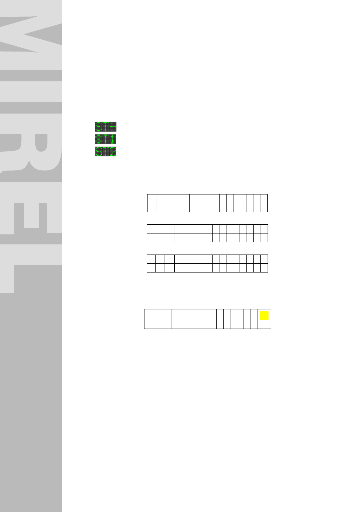
Indication at inactive cab of indication unit:
n
n
n
n
Depending on system configuration, the indication unit at inactive cab allows equal indication like at
active cab, without the option to enter a command to terminate a system intervention.
n
Indication at inactive cab of identification unit:
· control is enabled on none or both cabs
· control is enabled at cab No.1
none or both cabs have engaged control
control has been engaged at cab No.1
control has been engaged at cab No.2
A k t í v n e
s t a n o v i š t e S T -
A k t í v n e
s t a n o v i š t e S T 1
· control is enabled at cab No.2
A k t í v n e
s t a n o v i š t e S T 2
n
Depending on system configuration, the identification unit at inactive cab allows an equal indication
of identification and operation data like at the active cab, without possibility to issue commands to
central unit of MIREL RM2 Integrated On-Board System. In such case, the sign ENTER, which
indicates to staff the possibility to enter into indication mode, isn´t displayed in the right top corner.
A k t í v n e
s t a n o v i š t e S T 1
n
If no pushbuttons is pressed on the keyboard of the identification unit for 120 seconds
· at active cab, the identification unit switches to saving mode, in which the display OIID4
indicates time and date values moving on display.
· at inactive cab, the identification unit switches to saving mode, in which the display OIID4 is
switched off.
¿
1986RM2 : 180214 17
Page 18
. .
¿
¿
¿
¿
¿
¿ ↑
8 Login, Navigation in Menu and Logoff
Login
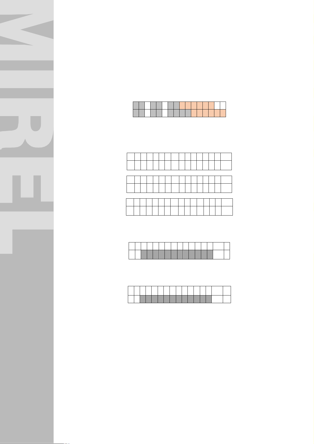
After accomplishment of D1 diagnostic test, the staff at identification unit of the active cab is prompted to
system login. Following steps must be done for login:
n
Operate any of keys on identification unit in case, when the screen saving mode indicating time and
date has already been activated, see Figure. Grey fields represent structure of indicated information
and orange fields represent movement limitation for time displayed on screen. Movement of
displayed time is slow and ensures a more balanced load of fluorescent display pixels.
: :
n
After login prompting, it is necessary to push the key¿. Chosen language is indicated in right top
corner, as well as system version of MIREL RM2. By cyclical pushing the key ESC, the DRV staff is
given the possibility to change language and subsequently to confirm selected language by key
.
M I R E L R M 2 [ S K ] v 0 1
P r i h l á s t e s a
M I R E L R M 2 [ P L ] v 0 1
Z a l o g u j s i ę
M I R E L R M 2 [ H U ] v 0 1
J e l e n t k e z z e n
n
Then the staff is prompted to enter the staff ID, which has to be entered with keys 0 to 9. The
entered value is necessary to confirm by pushing the key ¿ or cancel with ESC key. By
cancelling, the screen with prompting the login appears again.
Č í s l o o b s l u h y
_
n
After confirmation of entered staff ID the identification unit indicates the valid value of staff ID No.
With a valid (non-zero) staff ID, the identification unit allows navigation on screens in its menu by
displayed pushbuttons ↑,↓,¿ and unindicated ESC pushbutton.
Č í s l o o b s l u h y
↓
If the operator of DRV does not log off before turning off the system and turning it on in 10 min, the logins
remain valid and system does not require logging in again.
Navigation in Menu
With a valid (non-zero) staff ID, the identification unit allows navigation on screens in its menu by displayed
pushbuttons ←,↑,↓,→,¿ and unindicated ESC pushbutton. Navigation in menu follows rules provided
below:
n
Main menu items are numbered and movement among them is possible with help of navigation
pushbuttons:
· ← movement to the left until first item No. 1
· → movement to the right until last item No. 1
· ↓ shifting to submenu of respective item in main menu
· ESC inducement of logoff prompting
1986RM2 : 180214 18
Page 19

¿
n
Items in submenu aren´t numbered and movement among them is possible with help of navigation
pushbuttons:
· ↑ upward movement up to the highest submenu item and subsequently jog to
corresponding main menu item
· ↓ downward movement down to the lowest submenu item
· ESC return to main menu
Logoff
Logoff allows the staff a fast deleting of all entered identification data. DRV staff logoff can be carried out
as follows:
n
At any position in menu staff 2x operates the ESC pushbutton.
n
Staff enters the changed staff ID and confirms staff No. 0.
Logoff by pressing the ESC pushbutton results an indication of logoff confirmation screen:
S k u t o č n e
o d h l á s i ť ?
In case of logoff confirmation with pushbutton¿ the identification unit switches to login prompting screen.
If the logoff dialogue is cancelled with ESC pushbutton, the identification unit switches to first item of main
menu. Logoff inducement by entering of number 0 and subsequent confirmation of staff ID in submenu, the
staff is logged off immediately.
Staff identification is enabled on identification unit at active cab of MIREL RM2 Integrated On-Board
System or on board terminals wired to communication interface of MIREL RM2 Integrated On-Board
System depending on system configuration.
Menu Identification („1.Identifikácia“) on identification unit allows entering of below provided data:
n
Operating staff ID
n
Train No.
n
Forwarder ID
n
DRV mode
n
Train weight
n
Train length
Menu Identification („1.Identifikácia“) comprises also items, which can be displayed but can´t be edited
n
DRV No.
n
Snum – system number of MIREL RM2
n
Diameter – wheel flange diameter
Operating staff ID
DRV staff logs in MIREL RM2 Integrated On-Board System by entering a non-zero value into item Staff ID
(„Číslo obsluhy“). Other items in group Identification („1.Identifikácia“) are optional and become zeroed
after DRV staff logoff.
The item Staff ID („Číslo obsluhy“) is accessible from main item Identification („1.Identifikácia“) by pushing
the key ↓. The item edit mode is induced with pushbutton ¿. Item can contain maximum 12 digit
number. DRV staff logoff is possible from any item in main menu after pushing ESC key and confirmation
with pushbutton ¿.
1986RM2 : 180214 19
Page 20

Train No.
The item Train No. („Číslo vlaku“) from main item Identification („1.Identifikácia“) is accessible with 2x push
the key ↓. The item edit mode is induced with pushbutton ¿. Item can contain maximum 12 digit
number. The item Train No. is for operation of MIREL RM2 Integrated On-Board System optional.
Forwarder ID
The item Forwarder ID („Číslo dopravcu“) from main item Identification („1.Identifikácia“) is accessible with
3x push the key ↓. The item edit mode is induced with pushbutton ¿. Item can contain maximum 4 digit
number. The item Forwarder ID is for operation of MIREL RM2 Integrated On-Board System optional.
DRV Mode
The item DRV Mode („Režim HDV“) from main item Identification („1.Identifikácia“) is accessible with
operating 4x the key ↓. By pushbutton ¿ the item edit mode is induced. The item can obtain values
below:
n
TRAIN („VLAKOVÝ“) (pushbutton 1)
n
BIASING („PRÍPRAŽNÝ“) (pushbutton 2)
n
BANKING („POSTRKOVÝ“) (pushbutton 3)
n
SHUNTING („POSUNOVACÍ“) (pushbutton 4)
n
FAULT („PORUCHA“) (pushbutton 5)
n
SERVICE („SERVIS“) (pushbutton 6)
n
LV (pushbutton 7)
n
USER MODE 1 („UŽIVATEĽSKÝ REŽIM 1“) (pushbutton 8)
n
USER MODE 2 („UŽIVATEĽSKÝ REŽIM 2“) (pushbutton 9)
n
NON-ASSIGNED („NEZADANÝ“) (pushbutton 0)
The item DRV Mode is for operation of MIREL RM2 Integrated On-Board System optional.
Train Weight
The item Train Weight („Hmotnosť vlaku“) from main item Identification („1.Identifikácia“) is accessible with
5x pushing the key ↓ . The item edit mode is induced with pushbutton ¿. Item can contain maximum 4
digit number indicating the train weight in tons. The item Train Weight is for operation of MIREL RM2
Integrated On-Board System optional.
Train Length
The item Train Length („Dĺžka vlaku“) from main item Identification („1.Identifikácia“) is accessible with 6x
pushing the key ↓. The item edit mode is induced with pushbutton ¿. Item can contain maximum 4 digit
number indicating the train length on metres. The item Train Length is for operation of MIREL RM2
Integrated On-Board System optional.
DRV No.
The item DRV No. („Číslo HDV“) from main item Identification („1.Identifikácia“) is accessible with 7x
pushing the key ↓. Each railway vehicle gets assigned a unique 12 digit number, which identifies the
vehicle in operation. The number is displayed in UIC format. The item is inserted into system by Producer
in course of system installation configuration.
Snum and Diameter
The item Snum and Diameter („Snum“ a “Priemer”) from the main item Identification („1.Identifikácia“) is
accessible with 8x pushing the key ↓. Each MIREL system is assigned a unique number, which system
gets from the system manufacturer. The Diameter indicates the value of the actual set diameter of the
wheel flange in the system. The item is inserted to the system during configuration of the system.
1986RM2 : 180214 20
Page 21

¿ →
¿
9 Selection of System Operating Mode
Start-up into Operating Mode
After accomplishment of D1 diagnostic test, the system switches to operating mode based on rules stated
below.
n
If mode selector is in the zero position, the system switches to SHUNTING / OPERATION
(„POSUN / PREVÁDZKA“) mode, dependent on system configuration.
n
If mode selector is in a non-zero position, the system switches to WORK / DEAD-IN-TOW
(„PRÁCA / ZÁVES“) mode, dependent on system configuration.
Operating Mode Indication
The actual operating mode of MIREL RM2 Integrated On-Board System is indicated as follows:
n
On indication unit:
· After system start-up and accomplishment of D1 diagnostic test before putting DRV into
movement
· 3 seconds after DRV stops
n
On identification unit:
· In main menu of identification unit in item 2.RM2Mode (“2.Režim RM2”).
Operating modes are indicated on indication unit as follows:
n
Operating mode SHUNTING („POSUN“) is indicated with abbreviation "POS"
n
Operating mode OPERATION („PREVÁDZKA“) is indicated with abbreviation "PRE"
n
Operating mode WORK („PRÁCA“) is indicated with abbreviation "PRA"
n
Operating mode DEAD-IN-TOW („ZÁVES“) is indicated with abbreviation "ZAV"
Change of Operating Mode
Change of MIREL RM2 Integrated On-Board System operating mode follows rules stated below.
n
Should DRV be motionless and the system mode selector is switched to zero position, system
switches to SHUNTING („POSUN“) mode.
n
Should DRV be motionless and the system mode selector is switched to a non-zero position,
system switches to WORK / DEAD-IN-TOW („PRÁCA / ZÁVES“) mode, dependent on system
configuration.
n
Should DRV be in motion and the system mode selector is switched to zero position, system
switches to SHUNTING („POSUN“) mode only after DRV stops.
n
Should DRV be in motion and the system mode selector is switched to a non-zero position, system
switches to WORK / DEAD-IN-TOW („PRÁCA / ZÁVES“) mode, dependent on system
configuration, only after DRV stops.
n
If the mode selector is in a non-zero position, switching of mode on identification unit of active cab
isn´t possible. The operating mode is set by configuration.
n
If the mode selector is in zero position, switching of mode on identification unit of active cab is
enabled.
The mode change is effectuated on identification unit as follows:
n
By selecting item No. 2 in main menu of identification unit
← 2 . R e ž i m R M 2
X : ↓
n
Subsequent operating the pushbutton ¿ for access to entry screen of system operating mode.
R e ž i m R M 2
_
n
With selection of pushbuttons 1 to 4 the corresponding operating mode is selected and indicated:
· SHUNTING („POSUN“) operating mode (pushbutton 1)
· OPERATION („PREVÁDZKA“) operating mode (pushbutton 2)
1986RM2 : 180214 21
Page 22

· WORK („PRÁCA“) operating mode (pushbutton 3). The selection of WORK („PRÁCA“)
operating mode is enabled only if it is permitted by system configuration.
· DEAD-IN-TOW („ZÁVES“) operating mode (pushbutton 4)
n
With operating mode selection and subsequent confirmation by pushbutton ¿ the system
switches to chosen mode.
n
Operating mode change by identification unit is possible only with a motionless DRV.
9.1 SHUNTING OPERATING MODE
The Integrated On-Board System MIREL RM2 operates in the SHUNTING („POSUN“) mode when DRV
is operated within stations, yards and when shunting with the driving vehicle. The modus is intended for
DRV movement at low speeds, with frequent driver´s cab change.
Vigilance Supervision
In SHUNTING („POSUN“) operating mode, the engine-driver is obliged to demonstrate vigilance by
operating vigilance pushbuttons in following cases, as stated below:
n
One-time after driving vehicle start
n
Cyclically, starting from movement speed of 20 km/h
n
Increased cyclical supervision after violating the maximum speed by more than 1 km/h.
If the engine-driver fail to confirm his vigilance after vigilance prompting, a system intervention (NZ1) takes
place and emergency brake gets activated.
System allows to confirm vigilance also with drive controllers, if wired to ZJ secure inputs and system
features configured function of vigilance confirmation with drive controllers.
Maximum Speed Supervision
In the SHUNTING („POSUN“) operating mode, the MIREL RM2 Integrated On-Board System supervises
the DRV travel speed in comparison with DRV maximum speed. When violating maximum speed by more
than 3 km/h, numeric indicator of actual speed OIIN6 starts flashing. When violating maximum speed more
than 5 km/h the acoustic signalling of the maximum speed is activated and after violating maximum speed
of 7 km/h a system intervention (NZ2) takes place by means of emergency brake activation.
Maximum speed in a given moment is determined as the lowest among following ones:
n
maximum vehicle design speed, determined by configuration
n
maximum speed for operating mode
n
maximum speed determined by cooperating device MIREL VZ1
Maximum speed for SHUNTING („POSUN“) operating mode has been set to 40 km/h and the enginedriver hasn´t any possibility to alter this maximum speed.
Supervision of Accord Between Actual and Selected Travel Direction
In the SHUNTING („POSUN“) operating mode, the RM2 supervises accord of actual travel direction with
selected one. Discord is evaluated for each movement of driving vehicle. Accord is required for movement
with any speed exceeding 5 km.h-1. At drive vehicle travel in a direction, which isn´t in accord with the
selected travel direction, up to a speed of 5 km/h the audible signalization ZS3 is activated with horn of
RM2 and in case when speed is exceeded by more than 5 km/h, after 10 m a system intervention (NZ3)
takes place and emergency brake gets activated. With turned off control switch at both rail vehicle driver´s
cabs, any movement is evaluated as movement in contrary with the selected travel direction. The
compliance is evaluated once at the start of the DRV.
9.2 OPERATION Operating Mode
In the OPERATION („PREVÁDZKA“) operating mode, all checking functionalities of MIREL RM2
Integrated On-Board System are activated. The mode is used during a standard operational drive of DRV.
Vigilance Supervision
In the OPERATION („PREVÁDZKA“) operating mode, the engine-driver is obliged to demonstrate
vigilance by operating the vigilance buttons in situations as follows:
n
One-time after the driving vehicle sets to motion
1986RM2 : 180214 22
Page 23

n
Cyclically during DRV movement
n
Increased Cyclical Supervision when maximum speed is violated by more than 1 km/h
Should the engine driver fail to confirm vigilance after vigilance prompting by pushing the vigilance
pushbutton or pedal, a system intervention (NZ1) takes place by emergency brake activation.
System allows to confirm vigilance also with drive controllers, if wired to ZJ secure inputs and system
features configured function of vigilance confirmation with drive controllers.
Maximum Speed Supervision
In the OPERATION („PREVÁDZKA“) operating mode, the MIREL RM2 Integrated On-Board System
supervises the DRV travel speed in comparison with DRV maximum speed. When violating maximum
speed by more than 3 km/h, numeric indicator of actual speed OIIN6 starts flashing. When violating
maximum speed more than 5 km/h the acoustic signalling of the maximum speed is activated and after
violating maximum speed of 7 km/h a system intervention (NZ2) takes place by means of emergency
brake activation.
Maximum speed in a given moment is determined as the lowest among following ones:
n
maximum vehicle design speed, determined by configuration
n
maximum speed determined by cooperating device MIREL VZ1
Maximum design speed is determined by configuration and the engine-driver hasn´t any possibility to alter
this maximum speed.
Supervision of Accord Between Actual and Selected Travel Direction
In the OPERATION („PREVÁDZKA“) operating mode, the RM2 Integrated On-Board System supervises
accord of actual travel direction with selected one. Discord is evaluated for each movement of driving
vehicle. Accord is required for movement with any speed exceeding 5 km.h-1. At drive vehicle travel in
a direction, which isn´t in accord with the selected travel direction, after 10 m a system intervention (NZ3)
takes place and emergency brake gets activated. With turned off control switch at both rail vehicle driver´s
cabs, any movement is evaluated as movement in contrary with the selected travel direction. The
compliance is evaluated once at the start of the DRV.
9.3 WORK Operating Mode
The Integrated On-Board System MIREL RM2 operates in operating mode WORK („PRÁCA“) during
execution of technological activities with driving rail vehicle. The mode is suitable for duty, measurement
and other special railway vehicles, where the staff operates in work mode the technological section of
vehicle.
Vigilance Supervision
In the WORK („PRÁCA“) operating mode, the engine-driver is obliged to demonstrate vigilance by pushing
the vigilance buttons in situations as follows:
n
Cyclically starting from speed as set in configuration, but maximum starting from speed of 40 km/h
n
Increased Cyclical Supervision when maximum speed is violated by more than 1 km/h
Should the engine driver fail to confirm vigilance after vigilance prompting by pushing the vigilance
pushbutton or pedal, a system intervention (NZ1) takes place by emergency brake activation.
System allows to confirm vigilance also with drive controllers, if wired to ZJ secure inputs and system
features configured function of vigilance confirmation with drive controllers.
Maximum Speed Supervision
In the WORK („PRÁCA“) operating mode, the MIREL RM2 Integrated On-Board System supervises the
DRV travel speed in comparison with DRV maximum speed. When violating maximum speed by more
than 3 km/h, numeric indicator of actual speed OIIN6 starts flashing. When violating maximum speed more
than 5 km/h the acoustic signalling of the maximum speed is activated and after violating maximum speed
of 7 km/h a system intervention (NZ2) takes place by means of emergency brake activation.
Maximum speed in a given moment is determined as the lowest among following ones:
1986RM2 : 180214 23
Page 24

n
maximum vehicle design speed, provided by configuration
n
maximum speed for operating mode in WORK („PRÁCA“) mode
n
maximum speed determined by cooperating device MIREL VZ1
Maximum design speed for WORK („PRÁCA“) operating mode is determined by configuration and the
engine-driver hasn´t any possibility to alter this maximum speed.
Supervision of Accord Between Actual and Selected Travel Direction
In the operating mode PRA RM2 doesn´t supervise accord and discord between actual and chosen travel
direction.
9.4 DEAD-IN-TOW Operating Mode
The integrated on-board system operates in the DEAD-IN-TOW („ZÁVES“) operating mode during banking
of driving railway vehicle or on train DRV when more DRVs are arranged at the train front.
Vigilance Supervision
In the DEAD-IN-TOW („ZÁVES“) operating mode, the engine driver´s vigilance isn´t supervised.
Maximum Speed Supervision
In the DEAD-IN-TOW („ZÁVES“) operating mode, the MIREL RM2 Integrated On-Board System
supervises the DRV travel speed in comparison with DRV maximum design speed. When violating
maximum speed by more than 3 km/h, numeric indicator of actual speed OIIN6 starts flashing. When
violating maximum speed more than 5 km/h the acoustic signalling of the maximum speed is activated and
after violating maximum speed of 7 km/h a system intervention (NZ2) takes place by means of emergency
brake activation.
Maximum design speed is determined by configuration and the engine-driver hasn´t any possibility to alter
this maximum speed.
Supervision of Accord Between Actual and Selected Travel Direction
In the operating mode ZAV RM2 doesn´t supervise accord and discord between actual and chosen travel
direction.
1986RM2 : 180214 24
Page 25
10 Overview of System Functions
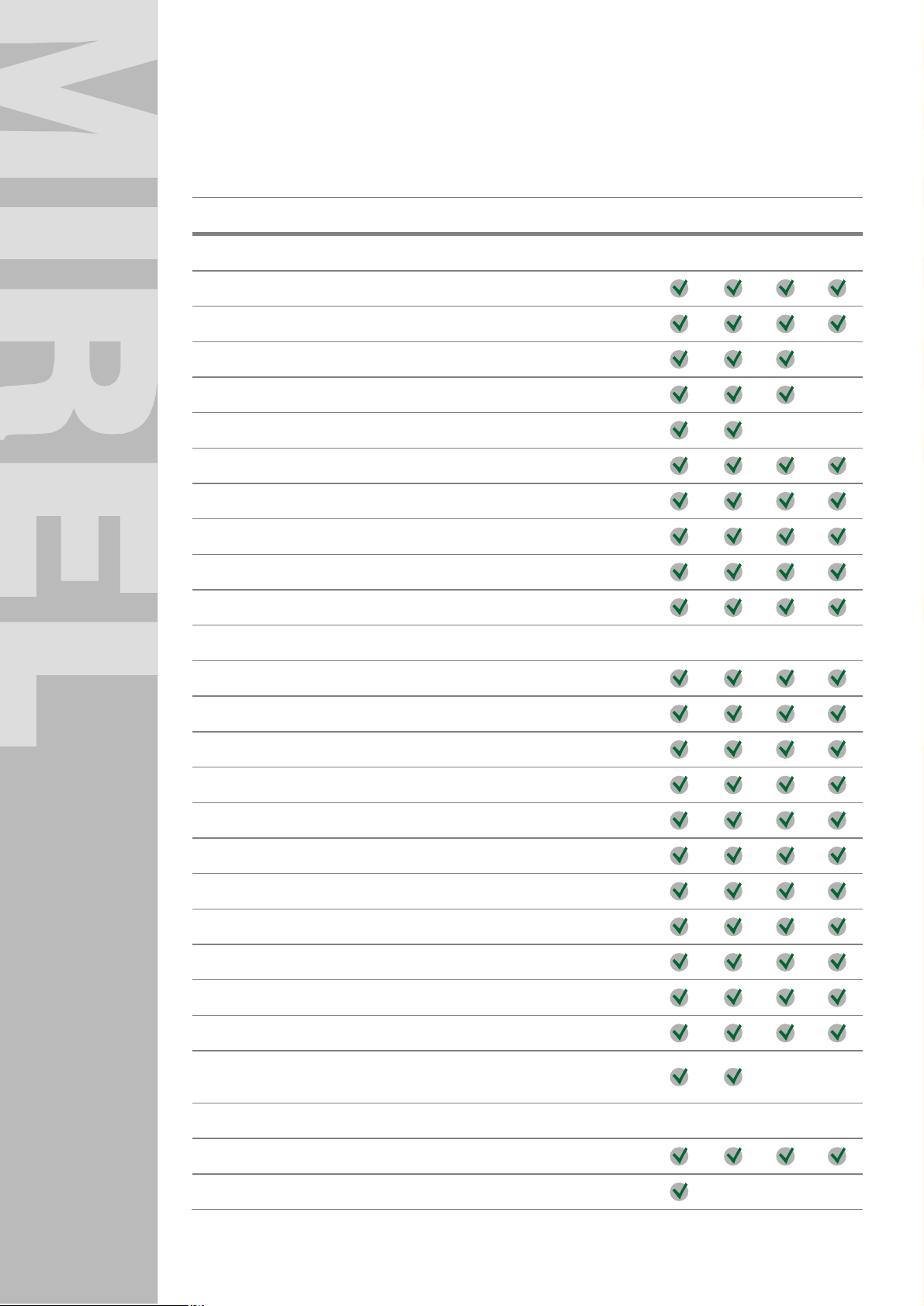
The MIREL RM2 Integrated On-Board System implements safety, operational and system functions in
extent as provided in summary below. Apart from that, the availability of individual functions can be limited
by required configuration of system functional properties.
Description of Function POS PRE PRA ZAV
SAFETY OPERATIONAL FUNCTIONS
Odometry
Movement speed indication
Cyclical vigilance supervision
Increased cyclical vigilance supervision
One-time vigilance supervision after setting DRV into movement
Maximum design speed supervision
Supervision of maximum speed for operating mode
Operational system intervention
Control of safety outputs
Provision of safety-relevant data to communication interface
OPERTIONAL FUNCTIONS
Indication of maximum permitted speed
Indication of preset speed
Data collection from technology interface
Data collection from communication interface
Operating data registration
System data registration
Communication via GSM gateway
Control of technological binary outputs
Provision of data to communication interface
GPS localization
Train remote stop
Check of DRV movement direction in relation to direction controller
setting
SYSTEM FUNCTIONS
Clock synchronization
System start-up
1986RM2 : 180214 25
Page 26
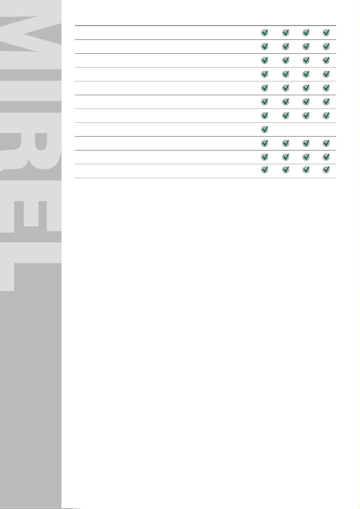
Selection of active cab
Setting of operating modes
Audible indication
Visual indication
Indicator brightness regulation
Termination of system operation
Error detection and system intervention
One-time diagnostic test D1
Repeated daily diagnostic test D1
Continuous diagnostic test D2
Functional test D3
1986RM2 : 180214 26
Page 27

11 Safety Operation Functions
11.1 Odometry
System carries out all odometry measurements by means of incremental sensor IRC. Technical
parameters as well as measurement evaluation method have been specified in document 1976RM2
Technical Conditions.
11.2 Movement Speed Indication
The indication of actual movement speed is one of fundamental functions of MIREL RM2 Integrated OnBoard System. The DRV movement speed is interpreted in km/h in a way dependent on employed
indication device.
Actual speed can be interpreted as follows:
n
In analogue method on dial speed indicator and simultaneously as an integer on triple-character
alphanumeric indicator OIIN6 on indication device RM2IN.1 or RM2IN.2
n
as an integer on triple-character alphanumeric indicator OIIN6 on indication device RM2IN.S
n
numerically in submenu of main item Oper.data („3.Prev. údaje“). - „DRV Movement Speed“ on
identification unit RM2ID
n
on board terminals wired to communication interface of MIREL RM2 Integrated On-Board System.
11.3 Vigilance Supervision
The MIREL RM2 Integrated On-Board System carries out, dependent on system configuration, the driver´s
vigilance supervision by providing optical/audible vigilance promptings, which must be confirmed by engine
driver with vigilance pushbuttons or pedals. The system allows vigilance confirmation also with drive
controllers, if wired to ZJ secure inputs and system features configured function of vigilance confirmation
with drive controllers. If the MIREL RM2 Integrated On-Board System provides for function of vigilance
supervision, on each rail vehicle cab a combination of vigilance pushbuttons and/or vigilance pedals is
located. If control switch has been engaged at respective cab, all pushbuttons and pedals in this cab are
equal and vigilance can be confirmed by anyone of them.
The system allows vigilance confirmation also with drive controllers, if wired to ZJ secure inputs and
system features configured function of vigilance confirmation with drive controllers.
Vigilance pushbutton or pedal must be pressed for a period of at least 100 ms. A permanent pressing of
pushbutton or pedal doesn´t result in repeated vigilance confirmation. The maneuver with drive controllers
confirms vigilance if the transition between positions will last for at least 100 ms.
Vigilance confirmation is possible only if, blue light isn´t lit on indication unit RM2IN.S. Vigilance
confirmation is signalized on indication unit RM2IN.S by lighting-up the blue light. Should the engine-driver
operate a vigilance pushbutton or pedal when the blue light is lighting, system audibly notifies driver about
unrequired vigilance confirmation (ZS8). 3,5 seconds prior to expiry of interval for vigilance confirmation,
the system provides to driver an audible vigilance prompting (ZS1), the horn (HP1 / HP2) is activated with
a permanent tone. The audible vigilance prompting alerts the engine-driver about the acute obligation to
confirm vigilance. If he/she fails to do so until end of set time interval, a system intervention (NZ1) occurs
by brake EPV opening, which results in DRV emergency braking.
The vigilance supervision can be a cyclical one or one-time and is carried out dependent on active system
operating mode. Based on needs of system operator, the vigilance supervision can be influenced by
system configuration, e.g. it can be entirely de-activated in specific cases.
Function implementation in the given operating mode
Cyclical vigilance supervision
Increased cyclical vigilance supervision
1986RM2 : 180214 27
POS PRE PRA ZAV
–
–
Page 28

-
1
One-time vigilance supervision after setting DRV
into movement
– –
11.4 Cyclical Vigilance Supervision
Cyclical vigilance supervision is a standard way of driver´s vigilance supervision, which is implemented
when operating system in operating modes SHUNTING („POSUN“), OPERATION
(„PREVÁDZKA“), WORK („PRÁCA“) and DEAD-IN-TOW („ZÁVES“) according to following rules:
Operating
mode
POS
PRE
PRA
ZAV
Prerequisites of function implementation in a given operating mode
Cyclical vigilance supervision is required when meeting of following condition:
n DRV speed ≥ 20 km/h
Cyclical vigilance supervision is required when meeting of following condition:
n DRV speed > 0 km/h
Cyclical vigilance supervision is required when meeting of following condition:
n Cyclically, starting from speed set by configuration, but maximally from speed of
40 km/h
In the DEAD-IN-TOW („ZÁVES“) operating mode, the driver´s vigilance isn´t supervised
The interval of cyclical vigilance supervision depends on DRV speed, where the interval length of vigilance
supervision as well as length of lit blue light is specified in Table below:
time (tob)
Time to activation of audible
DRV speed
[km.h-1]
up to 30 6,0 20,5 24,0
up to 46 5,7 19,2 22,7
up to 62 5,3 17,8 21,3
up to 78 5,0 16,5 20,0
up to 94 4,7 15,2 18,7
up to 110 4,3 13,8 17,3
over 110 4,0 12,5 16,0
Time period of lit blue light
[s]
signalization
[s]
until
intervention
[s]
11.5 Increased Cyclical Vigilance Supervision
The increased cyclical vigilance supervision is a way of driver´s vigilance supervision in operating
situations requiring increased alertness and is carried out based on following rules:
Operating
mode
POS
PRE
PRA
ZAV
1986RM2 : 180214 28
Conditions of function implementation in a given operating mode
Upon violation of maximum speed by more than 1 km.h-1
Upon violation of maximum speed by more than 1 km.h-1
Upon violation of maximum speed by more than 1 km.h
In the DEAD-IN-TOW („ZÁVES“) operating mode, the driver´s vigilance isn´t supervised.
Page 29

The interval of cyclical vigilance supervision doesn´t depend on DRV speed. Interval length and length of
lit blue light is specified in Table below:
DRV speed
[km/h]
for all speeds 8,5 8,5 12
Time period of lit blue light
[s]
time to activation of audible
signalization [s]
time (tob)
until intervention [s]
11.6 One-Time Vigilance Check after Setting DRV into Motion
The function of one-time vigilance check after setting DRV into motion is active in operating modes
SHUNTING („POSUN“) and OPERATION („PREVÁDZKA“) and provides to engine-driver exactly one
standard vigilance prompting based on following rules:
Operating
mode
POS
PRE
Based on needs of system operator, the one-time vigilance check can be influenced by system
configuration.
Prerequisites of function implementation in a given operating mode
A one-time vigilance check is required when meeting following prerequisite:
n after setting DRV into motion
A one-time vigilance check is required when meeting following prerequisite:
n after setting DRV into motion
11.7 Maximum Design Speed Supervision
The maximum design speed is predetermined by DRV type on which the MIREL RM2 Integrated On-Board
System has been installed. Maximum design speed is constituent part of parameters, which make up the
system configuration. In course of initial system activation, the configuration is stored in system memory by
means of a service intervention.
It is not possible to alter the maximum DRV design speed, as stored in system, during system operation.
When railway vehicle properties change, or system is implemented on a different DRV type, the system
configuration can be altered by means of a new system intervention.
The maximum design speed is entered into system in km/h. The highest possible value of maximum
design speed, which can be configured, is 160 km/h. The function of maximum design speed supervision
is active in PRE and ZAV operating modes.
11.8 Supervision of Maximum Speed for Operating Mode
All operating modes have a predefined maximum speed. Maximum speed for an operating mode is
determined by configuration and the neither driving vehicle staff, nor the service personnel have any
possibility to change it. Maximum speed values for operating modes are provided in Table below:
Operating
mode
POS
PRE
1986RM2 : 180214 29
Prerequisites of function implementation in a given operating mode
n Integrated On-Board System MIREL RM2 checks the actual DRV movement speed
compared with DRV maximum speed for this mode, which has been set to 40 km.h-1.
n When violating maximum speed by more than 3 km.h
flashing.
n When violating maximum speed by more than 5 km.h
starts
n When violating maximum speed by more than 7 km/h
violation is detected and emergency brake is subsequently activated (NZ2).
n Integrated On-Board System MIREL RM2 checks the actual DRV movement speed
compared with DRV maximum design speed, which is predestined by configuration.
n When violating maximum speed by more than 3 km.h
flashing.
-1
, actual speed indicator starts
-1
, the acoustic signalization
error of maximum speed
-1
, actual speed indicator starts
Page 30

-
1
Operating
mode
PRA
ZAV
Prerequisites of function implementation in a given operating mode
n When violating maximum speed by more than 5 km.h
, the acoustic signalization
starts
n When violating maximum speed by more than 7 km/h
error of maximum speed
violation is detected and emergency brake is subsequently activated (NZ2).
n Integrated On-Board System MIREL RM2 checks the actual DRV movement speed
compared with DRV maximum speed for this mode, which is determined by
configuration. When violating maximum speed by more than 3 km/h actual speed
indicator starts flashing.
n When violating maximum speed by more than 5 km.h
-1
, the acoustic signalization
starts
n When violating maximum speed by more than 7 km/h
error of maximum speed
violation is detected and emergency brake is subsequently activated (NZ2).
n Integrated On-Board System MIREL RM2 checks the actual DRV movement speed
compared with DRV maximum design speed, which is predestined by system
configuration and the engine-driver hasn´t any possibility to change this maximum
speed.
n When violating maximum speed by more than 3 km.h
-1
, actual speed indicator starts
flashing.
n When violating maximum speed by more than 5 km.h
-1
, the acoustic signalization
starts
n When violating maximum speed by more than 7 km/h
error of maximum speed
violation is detected and emergency brake is subsequently activated (NZ2).
11.9 Operational System Intervention
Reason of intervention of MIREL RM2 Integrated On-Board System is the occurrence of any from following
events:
Indication on
OIIN6 indicator
NZ1 NZ
NZ2 NZ
NZ3 NZ
NZ6 NZ
The MIREL RM2 Integrated On-Board System intervenes by opening EPV, which results in DRV
emergency brake activation. The intervention of MIREL RM2 Integrated On-Board System is indicated by
flashing indicator NZ (OIIN 3) on indication unit RM2IN. During DRV movement, the system intervention is
indicated by flashing speed value on indicator OIIN6 until complete vehicle halt. After DRV halt, the sign
NZ is displayed on indicator OIIN6 as well as index of reason leading to emergency stop.
The intervention can be terminated only after elimination of reasons leading to intervention and, along with
it, the DRV has achieved zero speed.
Reason for intervention NZ1 is missing DRV staff vigilance confirmation by operating the vigilance
pushbutton or vigilance pedal at active cab in determined time. Staff is alerted to obligation of vigilance
confirmation by means of an audible prompting ZS1. Should the vigilance confirmation not occur within
3,5 s after audible prompting, a system intervention occurs by EPV opening.
During DRV braking action:
Indication on
OIIN3 indicator
Indication on
OIIN4 indicator
Missing vigilance confirmation required by
Maximum speed violation
Discord between movement speed and
DRV motion before D1 accomplishment
Reason
provided vigilance prompting
direction controllers
1986RM2 : 180214 30
Page 31

¿
¿
¿
¿
n indicator OIIN3 displaying NZ flashes and after DRV halts, it switches to permanent displaying of
NZ.
n indicator OIIN6 displays DRV movement speed and after DRV halts, NZ1 is displayed.
Only after complete DRV halt, the staff can terminate intervention by pushing the command pushbutton
(OIIN7) on indication unit RM2IN.S of active cab. Along with end of intervention, the display NZ on
indicator (OIIN3) goes off and the text NZ1 on indicator (OIIN6) will be replaced by indication of chosen
mode. Railway vehicle is ready for operation.
Reason for intervention NZ2 is violation of maximum permitted DRV speed in a given mode. If the
maximum permitted DRV speed is violated by more than 5 km/h, the DRV staff is alerted about this fact by
audible prompting ZS2. After violation of maximum permitted DRV speed by more than 7 km/h, a system
intervention occurs by opening of EPV.
During DRV braking action:
n indicator OIIN3 displaying NZ flashes and after DRV halts, it switches to permanent displaying of
NZ.
n indicator OIIN6 displays flashing DRV movement speed and after DRV halts, NZ2 is displayed.
Only after complete DRV halt, the staff can terminate intervention by operating the command pushbutton
(OIIN7) on indication unit RM2IN.S of active cab. Along with end of intervention, the display NZ on
indicator (OIIN3) goes off and the text NZ2 on indicator (OIIN6) will be replaced by indication of chosen
mode. Railway vehicle is ready for operation.
Reason for intervention NZ3 is a discrepancy between direction controller and actual direction of DRV
movement.
During DRV braking action:
n indicator OIIN3 displaying NZ flashes and after DRV halts, it switches to permanent displaying of
NZ.
n indicator OIIN6 displays flashing DRV movement speed and after DRV halts, NZ3 is displayed.
Only after complete DRV halt, the staff can terminate intervention by pushing the command pushbutton
(OIIN7) on indication unit RM2IN.S of active cab. Along with end of intervention, the display NZ on
indicator (OIIN3) goes off and the text NZ3 on indicator (OIIN6) shall be replaced by indication of chosen
mode.
Reason for intervention NZ6 is DRV motion prior to accomplishment of D1 diagnostic test. Intervention is
effectuated by opening EPV.
During DRV braking action:
n indicator OIIN3 displaying NZ flashes and after DRV halts, it switches to permanent displaying of
NZ.
n indicator OIIN6 displays flashing DRV movement speed and after DRV halts, NZ6 is displayed.
Only after complete DRV halt, the staff can terminate intervention by operating the command pushbutton
(OIIN7) on indication unit RM2IN.S of active cab. Along with end of intervention, the display NZ on
indicator (OIIN3) goes off and the text NZ6 is displayed on indicator (OIIN6). Already accomplished steps
of D1 are invalid, system requires execution of a complete D1 test, staff is informed about this fact by
indication D1 on display (OIIN6).
Each intervention MIREL RM2 Integrated On-Board System creates a registered record.
11.10 Control of Safety Outputs
The MIREL RM2 Integrated On-Board System features three safety outputs BSO1, BSO2 and BSO3.
Function of safety outputs is configurable dependent on required system properties.
Specification method of prerequisites for issuance of safety output has been defined in document 1985 –
Specification of Configurations.
1986RM2 : 180214 31
Page 32

11.11 Provision of Safety-Relevant Data to Communication Interface
Specification for provision of safety-relevant data to communication interface has been defined in
document 1976RM2 – Technical Conditions.
1986RM2 : 180214 32
Page 33

12 Operational Functions
12.1 Indication of Maximum Permitted Speed
Indication of maximum permitted speed is identical with lowest one of speeds provided below
n
Maximum speed for chosen mode
n
Maximum DRV design speed
n
Maximum speed provided by MIREL VZ1 Train Protection
Maximum permitted speed is indicated on indication device RM2IN.1 and RM2IN.2 by a red lighting trace.
The trace lights within circular section determined by maximum permitted speed and end limit of indication
instrument scale. Maximum speed isn´t indicated on indication device RM2IN.S.
12.2 Indication of Preset Speed
MIREL RM2 Integrated On-Board System enables registration allows registration and in case with
application solution with indication device RM2IN.1 and RM2IN.2 also indication of preset speed with a
green lighting trace. The trace lights within circular section determined by zero speed and preset speed.
Preset speed isn´t indicated on indication device RM2IN.S. Indication of preset speed requires cooperation
of Integrated On-Board System MIREL RM2 with module of automatic speed regulation ARR or with
control system of driving railway vehicle. If value of railway vehicle´s preset speed isn´t available, zero
preset speed is indicated. Preset speed value is accessible in submenu of main item 3.Oper.data – presp.
(„3.Prev. údaje“. - „Vpredv“) on identification unit RM2ID.
12.3 Data Collection from Technology Interface
Technology interface of MIREL RM2 Integrated On-Board System enables collection and subsequent
registration of application-specific data from DRV technology, which have a direct linkage with DRV
technology. The function doesn´t require staff cooperation.
12.4 Data Collection from Communication Interface
The Integrated On-Board System MIREL RM2 carries out data collection from communication interfaces of
MIREL RM2 on-board system for the purpose of their processing and subsequent registration of
application-specific data from cooperating DRV elements.
The function doesn´t require staff cooperation.
12.5 Registration of Operational and System Data
The Integrated On-Board System MIREL RM2 with functional property “R” provides for registration of
operational and system data according to security level on one (SIL0) or simultaneously on two (SIL4) data
storage, due to which the data availability is ensured also in case of problems with one storage medium.
User has access only to storage medium in central unit on position of module B. It is prohibited to
manipulate with this medium when system is ON. In case of functional property “S” the data are stored on
another storage medium according to term EN62625-1. Data range registered to this medium is given by
the configuration of registration and it does not have to be identical to range of registration on operating
medium.
Data Transfer from Integrated On-Board System
Data registered by integrated on-board system are recorder on SD-type card. Recorded data can be
obtained for evaluation from MIREL RM2 Integrated On-Board System in following ways:
n
Taking out the user-accessible storage medium of MIREL RM2 Integrated On-Board System. Data
download into PC can be carried out by an authorized person of Operator, Producer of MIREL
RM2 Integrated On-Board System and other persons according to valid rules
1986RM2 : 180214 33
Page 34

n
Taking out the backup storage medium of MIREL RM2 Integrated On-Board System. Handling with
media is permitted only to a person authorized by Producer of MIREL RM2 Integrated On-Board
System.
n
From central database, where data are stored online by sending registered data via GSM
communication gateway to server.
Evaluation of Registered Data
Module MAN from the MIREL MAP application program equipment serves for evaluation of registered
data.
12.6 Communication via GSM Gateway
The Integrated On-Board System MIREL RM2 enables, dependent on chosen configuration, transfer of
operational and system parameters to remote server of the LANIX system. Data transfer can be carried
out by module wired to the Integrated On-Board System MIREL RM2 via serial interface RS485. Utilized
can be cooperating device MIREL LCM or internal module MIREL GGAM, which is installed directly in
central unit of MIREL RM2 Integrated On-Board System.
MIREL LCM as well as MIREL GGAM contain GSM communication module, through which it is possible to
send online data to remote server. Data transfer runs automatically, without need for DRV staff
intervention.
12.7 Control of Technological Binary Outputs
Dependent on needs of DRV Operator, the Integrated On-Board System MIREL RM2 can be equipped
with module of technology outputs. Control of technological binary outputs is, pursuant to needs of DRV
Operator, implemented dependent on independent time and track scale in real time and is predestined by
system configuration.
Technological binary outputs are utilized in applications with meaning:
BO1 – technological output for wheel flange lubrication
BO2 – technological output wheel flange lubrication
BO3 – technological output for error issue of wheel flange lubrication
BO4 – technological speed output 1
BO5 – technological speed output 2
BO6 – technological output error issue of wheel flange lubrication (4 imp/m)
Function parameters of wheel flange lubrication are predestined by system configuration. The function is
autonomous and doesn´t require staff cooperation.
Function parameters of speed outputs are predestined by system configuration. The function is
autonomous and doesn´t require staff cooperation.
Issue of track pulses is activated by system configuration. The function is autonomous and doesn´t require
staff cooperation.
12.8 Data Provision to Communication Interface
The MIREL RM2 Integrated On-Board System provides available on identification unit or eventually on
communication interface following basic data for board terminals:
n
System time
n
Time remaining until D1
n
Operating hours 1 (utilization based on system configuration)
n
Operating hours 2 (utilization based on system configuration)
n
Operating hours 3 (utilization based on system configuration)
n
Operating hours 4 (utilization based on system configuration)
n
DRV daily covered distance
1986RM2 : 180214 34
Page 35

¿ ↑
¿
n
DRV user-covered distance
n
Total DRV- covered distance
n
DRV movement speed
n
Maximum permitted speed
n
Preset speed
n
Wheel flange diameter
n
DRV position
System Time
System time and date is indicated in item Time („Čas“), which is located in submenu of main item
Oper.data („3.Prev. údaje“). The item Time („Čas“) from main item Oper.data („3.Prev. údaje“) is
accessible by pushing the key ↓. The time item indicates the actual date and time of system. Time is
provided in format hh:mm:ss. Date is provided in format DD.MM.YYYY.
Time Remaining Until D1
Time remaining until D1 is indicated in item time remaining until D1 („Čas do D1“), which is located in
submenu of main item Oper.data („3.Prev. údaje“). The item time remaining until D1 („Čas do D1“) from
main item Oper.data („3.Prev. údaje) is accessible by pushing 2x the key ↓. The item Time Remaining
until D1 indicates time remaining until initializing the subsequent daily self-diagnostic test D1. Time is
provided in format hh:mm:ss.
Operating Hours 1, 2, 3 and 4
Operating Hours 1, 2, 3 and 4 are indicated in items Operating Hours 1 („Motoh1“) through Operating
Hours 4 („Motoh4”), which are located in submenu of main item Oper.data („3.Prev. údaje“). The item
Motohours 1, 2 („Motohodiny 1, 2“) from main item Oper.data („3.Prev. údaje“) is accessible by pushing 3x
the key ↓. The item „Motohodiny 3, 4“ from main item Oper.data („3.Prev. údaje“) is accessible by pushing
4x the key ↓. Operating hours indicate time in format hhhhh:mm. Conditions for time calculation are
dependent on system configuration.
User Signs
User signs are indicated in item User Sign („Uživ. značka”), which is located in submenu of main item
Oper.data („3.Prev. údaje“). The item User sign („Uživ. značky“) from main item Oper.data („3.Prev. údaje“)
is accessible by pushing 5x the key ↓. During analysis of data from registration module, the user signs are
displayed in form of a binary signal on time and track axis. User has available 8 user signs. User signs
allow user to register on command a sign/signs to registration archive. Issue procedure of time sign:
n
User sign screen selection.
U ž i v . z n a č k a
↓
n
Access to editing mode of user signs by operating pushbutton ¿.
U ž i v . z n a č k a
n
Entering of user sign combination by selection of pushbuttons 1 to 8 and issue of command for
registration by operating the pushbutton ¿.
After issue of command to register user signs, the preset user signs are registered in registration archive.
DRV Daily Covered Distance
The DRV daily covered distance is indicated in item „Sd“, which is located in submenu of main item
Oper.data („3.Prev. údaje“). The item DRV daily covered distance („Ubehnutá denná dráha HDV“) from
main item Oper.data („3.Prev. údaje“) is accessible by pushing 6x the key ↓. The daily covered distance is
indicated in kilometres with a precision of three decimal places, i.e. with a precision of one meter. The daily
covered distance is zeroed by switching on the system.
1986RM2 : 180214 35
Page 36

DRV User-Covered Distance
The DRV user-covered distance is indicated in item „Su“, which is located in submenu of main item
Oper.data („3.Prev. údaje“). The item DRV user-covered distance („Ubehnutá užívateľská dráha HDV“)
from main item Oper.data („3.Prev. údaje“) is accessible by pushing 6x the key ↓. The user-covered
distance is indicated in kilometres with a precision of three decimal places, i.e. with a precision of one
meter. The user covered distance is zeroed by switching on the system and command from staff by
pushing the pushbutton ¿ on relevant screen of active identification unit.
Total DRV-Covered Distance
The total DRV-covered distance is indicated in item „S“, which is located in submenu of main item
Oper.data („3.Prev. údaje“). The item Total DRV-covered distance („Ubehnutá celková dráha HDV“) from
main item Oper.data („3.Prev. údaje“) is accessible by pushing 7x the key ↓. The total covered distance is
indicated in kilometres with a precision of one decimal place, i.e. with a precision of hundred metres. The
total covered distance isn´t zeroed by any staff command.
1986RM2 : 180214 36
Page 37

DRV Movement Speed
The DRV speed is indicated in item „V“, which is located in submenu of main item Oper.data („3.Prev.
údaje“).The item DRV Movement Speed („Rýchlosť pohybu HDV“) from main item Oper.data („3.Prev.
údaje“) is accessible by pushing 7x the key ↓. The DRV movement speed is indicated in km/h with a
precision of one decimal place.
Maximum Permitted Speed
The maximum permitted speed is indicated in item „Vmax.“, which is located in submenu of main item
Oper.data („3.Prev. údaje“). The item Maximum Permitted Speed („Maximálna povolená rýchlosť“) from
main item Oper.data („3.Prev. údaje“) is accessible by pushing 8x the key ↓. Maximum permitted speed is
indicated in km/h. The value of maximum permitted speed is determined as the lower one of maximum
design speed and maximum speed of chosen RM2 mode.
Preset Speed
The preset speed is indicated in item „Vpredv.“, which is located in submenu of main item Oper.data
(„3.Prev. údaje“). The item Preset Speed („Predvolená rýchlosť“) from main item Oper.data („3.Prev.
údaje“) is accessible by pushing 8x the key ↓. The preset speed is indicated in km/h. The value of preset
speed represents the speed required for system providing for automatic speed regulation at DRV.
DRV Position
The DRV position is indicated in items „ZŠ“ and „ZD“, which are located in submenu of main item
Oper.data („3.Prev. údaje“). The item DRV Position („Poloha HDV“) from main item Oper.data („3.Prev.
údaje“) is accessible by pushing 10x the key ↓. Indication of actual DRV position is split into two items:
n
Indication of geographical latitude „ZŠ“
n
Indication of geographical longitude „ZD“
The position is indicated in format SS°mm’ss,ff“ (degrees, minutes, seconds, hundreds of seconds).
12.9 GPS Localization
If the gateways MIREL LCM, MIREL LSM are wired to Integrated On-Board System MIREL RM2 or when
the localization and synchronization module GGAM is present directly in central unit of the integrated onboard system, the system is able to record the railway vehicle position, when the GPS signal is received.
The actual position is simultaneously provided on communication interface and indicated on identification
unit in menu Oper.data („3.Prev. údaje“) under item Geographical length / Geographical width („Zem. Š /
Zem. D“).
12.10 Remote Train Stop
Decoding of train stop radio signal is carried out by the DRV radio station. The remote option stop is
conditioned by organizational settlement of this function on infrastructure side, as well as by technical
equipment of radio station at DRV. The Producer recommends in Installation Manual 1992RM2 the
method of connection and signal path to registration of train remote stop signal by a radio station.
12.11 Check of Accord Between Actual and Preset Direction
The MIREL RM2 Integrated On-Board System evaluates the movement direction of driving vehicle from
signals of axle speed sensor. Such evaluated movement direction is compared with direction selected by
direction controller at active driver´s cab. Their accord or discrepancy is checked. One of following 5
different cases can emerge during operation of driving vehicle.
1. If the rail vehicle moves, after setting into motion, in the direction, which is corresponding with the
direction chosen at active cab by the driver, then such movement direction is classified as permitted.
This permission of movement direction applies until the next stopping of drive vehicle, independent
from eventual further manoeuvres carried out with direction controllers by the driver.
2. If the movement direction, after setting railway vehicle into motion, wasn´t classified as permitted one,
and an opposite direction to actual one has been previously chosen at active cab, after covering a
1986RM2 : 180214 37
Page 38

distance of 3 m the system activates audible signal ZS3 and after covering a distance of 10 m system
intervention NZ3 takes place, as well as emergency brake activation.
3. If the movement direction, after setting railway vehicle into motion, wasn´t classified as permitted one,
and no direction has been chosen at active cab, then:
a) in PRE and VYL operating modes the system behaves identically like if the opposite direction
would have been set according to paragraph 2,
b) in POS and ZAV operating modes the accord isn´t checked.
4. If the diagnostic test D1 hasn´t been accomplished and pressure in main brake line is lower than
3,5 bar, then any vehicle movement direction is considered as permitted.
5. With steering control switch in OFF position an both cabs, save operating situation stated in clause 4,
any railway vehicle movement is evaluated like travel in prohibited direction and system feedback is
according to clause 2.
1986RM2 : 180214 38
Page 39

13 System Functions
13.1 Clock Synchronization
If the gateways MIREL LCM, MIREL LSM are wired to Integrated On-Board System MIREL RM2 or when
the localization and synchronization module GGAM is present directly in central unit of the integrated onboard system, the system is able to synchronize the system clock pursuant to world time, when the GPS
signal is received. This synchronization takes place:
n
During system start-up
(if a difference of >10 s has been detected during system run, the difference detected during last
RM2 run shall be applied)
n
If system runs longer than 24 h and motionless DRV longer than 1/2 hour.
The actually detected difference between on-board time and GPS time is applied
On-bard time in RTC is UTC and RM2 carries out its conversion to local time. Conversion is
unequivocal like with transition from summer to winter time and vice-versa.
The MIREL RM2 Integrated On-Board System provides the actual local time to communication interface
and indicates it on identification unit in menu Oper.data („3.Prev. údaje“) under item Time („Čas“).
13.2 System Start-Up
System start-up has been described in Chapter 6 Putting into Operation and Termination of Operation.
13.3 Selection of Active Driver´s Cab
Selection of active driver´s cab has been described in Chapter Chyba! Nenašiel sa žiaden zdroj
odkazov. Cab Activation.
13.4 Operation Mode Setting
Setting of operation modes has been described in Chapter Chyba! Nenašiel sa žiaden zdroj odkazov.
Selection of System Operating Mode.
13.5 Audible Indication
Each railway vehicle cab is equipped with a horn of MIREL RM2 Integrated On-Board System, which
audibly alerts the driver about necessity of a control action, or notifies him/her about conditions, which
emerge in MIREL RM2 Integrated On-Board System. Horn is available in two design options, as
a separate device, or a device to be fitted into control panel.
Audible signalling:
ZS1
One-Time/Standard vigilance prompting
start 3,5 s before expiry of vigilance control interval
termination upon vigilance confirmation
3,5 s
ZS2
1 s
1986RM2 : 180214 39
type permanent horn tone without fade-out
Maximum speed violation
start upon maximum speed violation,
with respective tolerance
(more than 5,5 km.h-1)
termination upon speed decrease under limit maximum speed
+ tolerance
(intervention of MIREL RM2 Integrated On-Board
Page 40
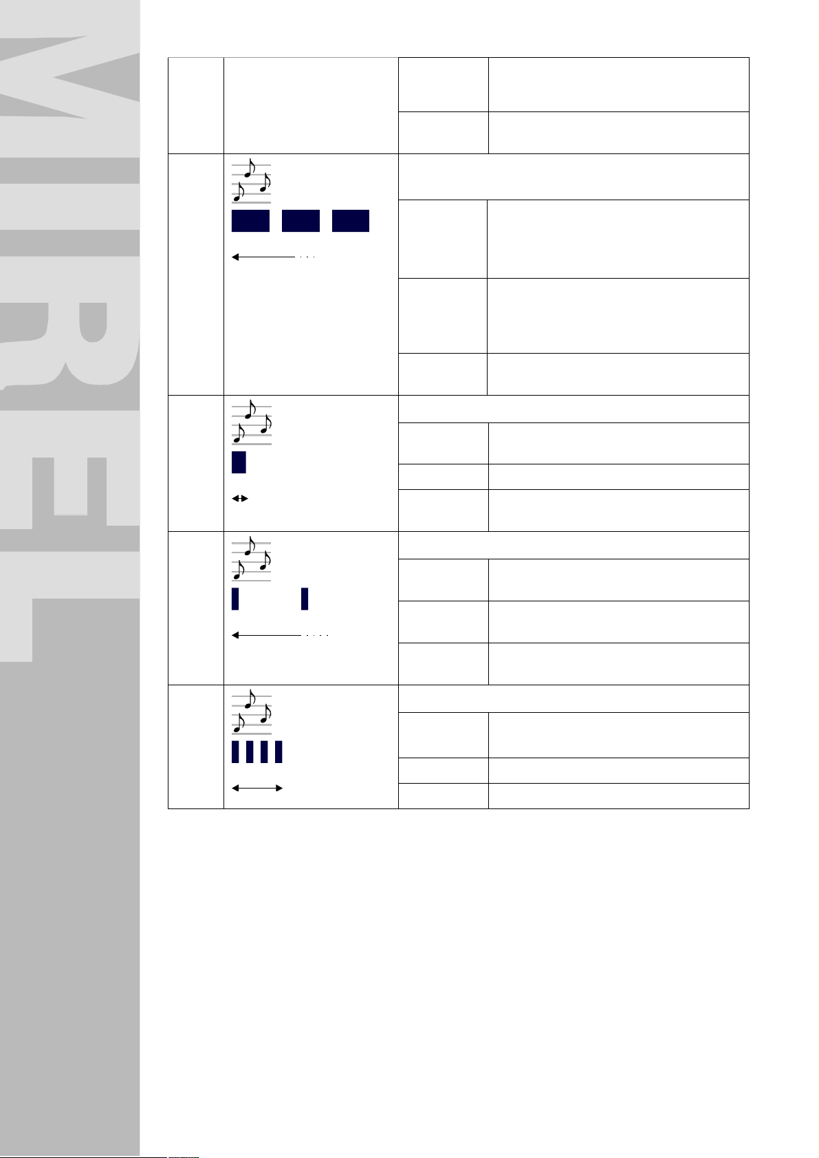
System due to maximum speed violation isn´t
a reason to terminate signalling of maximum
speed violation)
type fast interrupted horn tone
2,5 Hz with 1:1 buzz ratio
ZS3
ZS8
ZS10
0,2 s
1 s
Discrepancy between selected and actual DRV
movement direction
start after covering a distance of 6 m in prohibited
direction,
termination after covering a distance of 10 m in prohibited
Type slow interrupted horn tone
Notification about unrequested vigilance confirmation
start after pressing vigilance pushbutton or pedal,
termination One-time signal
type Audible signal with motive
Notification about repeated D1 execution
10 s before time interval expiry for start of DRV
setting into motion
direction and RM2 intervention, or after achieving
accord between actual and selected movement
direction
1,25 Hz with 3:1 buzz ratio
when blue light is lit
1 pulse (0,2 s)
start 15 s before automatic repeated start-up of D1
diagnostic test
termination upon start of D1 diagnostics, by postponing the
1 s
ZS11
0,7 s
The audible indication is enabled also by every identification and indication unit of MIREL RM2 Integrated
On-Board System. After operating any of pushbuttons, the unit issues a brief tone indicating to staff that a
pushbutton has been operated. With simultaneous operating of two or more pushbuttons, the unit doesn´t
issue any tone.
type short slow interrupted horn tone
Start of D1 diagnostics
start upon putting system into operation,
termination one-time signal
type 4 brief pulses (0,1 s)
D1 diagnostics execution for additional 15 minutes
1 Hz with 1:9 buzz ratio
after repeated D1 start
13.6 Visual Indication
The visual indication is enabled indication and identification units of MIREL RM2 Integrated On-Board
System, their quantity and types are dependent on chosen modification. Description of control and
indication elements of mentioned units is provided in Chapters 5.2 Indication Unit and 5.3 Identification unit
of underlying document.
1986RM2 : 180214 40
Page 41
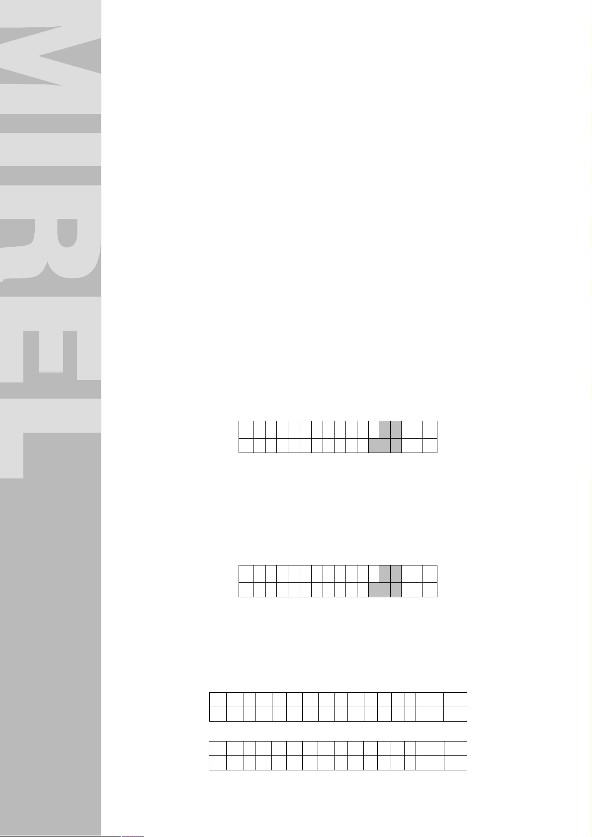
¿
¿
13.7 Regulation of Indicator Brightness
Each identification and indication unit of MIREL RM2 Integrated On-Board System is equipped with an
illumination intensity sensor. Indicator brightness regulation on indication and identification units is fully
automatic. Each identification and indication unit ensures the brightness regulation in autonomous way
based on light conditions in place of unit installation.
13.8 Termination of System Operation
Termination of system operation is described in Chapter 6 Putting into Operation and Termination of
Operation.
13.9 Error Detection and System Intervention
Errors of MIREL RM2 Integrated On-Board System have been divided in two groups. Serious errors, which
make further operation of MIREL RM2 Integrated On-Board System impossible and light errors, which limit
further operation of MIREL RM2 Integrated On-Board System.
Serious Error
Serious error makes further operation of MIREL RM2 Integrated On-Board System impossible. Upon
detection of a serious error, the MIREL RM2 Integrated On-Board System is switched into secure
condition. In case of modification of the system with functional property “B”, the secure condition is realized
by means of opening EPV, which results in emergency brake activation.
A serious error is indicated as follows:
n
by flashing of S indicator (OIIN4) on indication units RM2IN and of indicator (OIID2) on identification
units RM2ID
n
by flashing of indicated DRV movement speed on indication unit
n
on screen of active identification unit in Errors („4.Poruchy“) there is an indication how many
actually detected system errors are pending, along with code of first detected errors.
← 4 . P o r u c h y
K ó d : E ↓
Light Error
Upon origination of a light error, limiting further operation of RM2 Integrated On-Board System, system
permits operation with limitations based on error character.
A light error is indicated as follows.
n
By permanently lit ERR indicator (OIIN5) on indication units RM2IN and identification units RM2ID
n
on screen of active identification unit in Errors („4.Poruchy“) there is an indication how many
actually detected system errors are pending, along with code of first detected errors
← 4 . P o r u c h y
K ó d : E ↓
Due to incorrect operation of DRV staff, specific conditions can occur, which are indicated by system as
operating staff error.
Operating staff error is indicated as follows:
n
by permanently lit ERR indicator (OIIN5) on indication units RM2IN and identification units RM2ID
n
on screen of identification unit in menu Errors („4.Poruchy“).
D 1 p r e r u š e n á
D 1 n e v y k o n a n á
o ↑
o ↓
K o h ú t u z a v r e t
K ó d y p o r ú c h :
1986RM2 : 180214 41
ý
o
o ↑
↓
Page 42

Displaying of system errors
If there are more errors in the system, it is possible to display codes of all errors on the last screen.
x x , y y , z z
If there is more errors in the system which can be displayed on one screen, than the required number of
screens will be used to display all errors.
Zeroing of Errors
After emerging of a serious error, the staff re-initializes the MIREL RM2 Integrated On-Board System by
decoupling circuit breaker of MIREL RM2 Integrated On-Board System for a time period of min. 1 second
and subsequent engagement of circuit breaker, which results in zeroing of error indication. If an error is
indicated repeatedly, the driving vehicle staff doesn´t carry out any further actions.
Upon system re-initializing, the fact must be considered, that the system shall be initialized with preset
operating parameters.
A symptom of light error can be set to zero by staff by identification unit RM2ID of active cab in menu
Errors („4.Poruchy“) under fulfilment of condition, that error/reason for error signalling has vanished. The
indication of light error extinguishes after zeroing the symptom. Zeroing of light error symptom is carried
out by pushing the pushbutton¿.
↑
1986RM2 : 180214 42
Page 43

Error Codes
The table of error codes is listed in [3]1987RM2 Maintenance Manual, Diagnostics.
13.10 One-Time Diagnostic Test D1
The execution method of one-time diagnostic test D1 has been defined in Chapter 6 Putting into Operation
and Termination of Operation.
13.11 Repeated Daily Diagnostic Test D1
The execution method of repeated diagnostic test D1 has been defined in Chapter 6 Putting into Operation
and Termination of Operation.
13.12 Continuous Diagnostic Test D2
During the entire operation of MIREL RM2 Integrated On-Board System, the continuous self-diagnostic
test D2 is activated. The goal of D2 test is continuous monitoring of fault-free system operation. No
intervention of DRV staff is required for the operation of self-diagnostic test D2. In case of error detection
during execution of D2 test, the system switches itself to a safe condition.
13.13 Functional Test D3
The system enables to maintenance personnel the execution of D3 functional test. Functional test D3
verifies the correct operation of MIREL RM2 Integrated On-Board System as well as of cooperating, input
and output devices. A detailed description of D3 functional test execution has been specified in document
1987RM2 Maintenance Manual, Diagnostics.
1986RM2 : 180214 43
Page 44

14 Procedure in case of accident
If MIREL has functional property “R” or “R” and “S” it is possible to reconstruct the situation before an
accident by reading the registered data, parameters of drive and evaluate the correctness of the
executions performed by the DRV operator. If the accident has not caused irreversible damage of
removable registration medium in module ZJ-B, reading the data or the removal of the medium for the
competent authorities shall be carried out by the responsible operator. If this medium is damaged, reading
the data is realized by the manufacturer of the system, which proceeds according to the internal regulation
referred to [2]1984RM2 Technical reference.
1986RM2 : 180214 44
Page 45

15 Notes
1986RM2 : 180214 45
 Loading...