

Mircom TX3-TOUCH-S15S-WR, TX3-TOUCH-S15B-WR User Manual
TX3-TOUCH-S15B-WR and TX3-TOUCH-S15S-WR QUICK START
23 25/32”
21/32”
17 1/2”
12”
Mounting holes
3 13/32”
4 1/16”
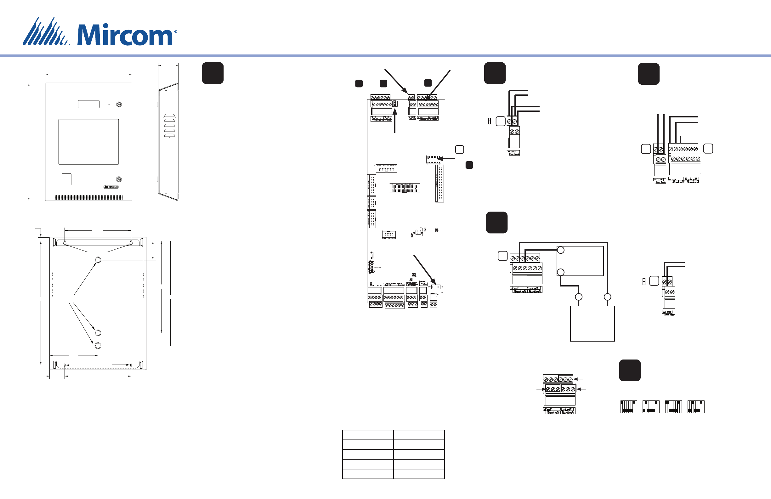
1
The enclosure mounts on the wall. Mount the
enclosure right-side up (the Mircom logo on the
door is in the lower right corner).
You need:
4 fasteners appropriate for the wall that you are
mounting the enclosure on.
1. Find a suitable location for the enclosure.
2. Mark the back mounting locations of the two top
3. Place the fasteners halfway into the wall in the
4. Place the enclosure onto the fasteners, then
5. Screw the other fasteners into the remaining
6. Tighten all fasteners into place.
Warning: To prevent water from
Mount the
Enclosure
screws. Ensure that at least one screw is over a
wall stud.
two top keyhole locations and wall stud.
lower it so that the fasteners t in the narrow
part of the keyholes.
holes.
entering the unit, use an elbow
connector to run the wires to one
of the three knockouts on the back.
16 15/32”
22 7/32”
For more details, see LT-996 and LT-969 on the Mircom website and the USB ash.
Mircom technical support: 1-888-647-2665
Knockouts
8 3/4”
Mounting holes
2 3/4” 12”
18 3/4”
The elbow connector must point
downwards.
Installation Prerequisites
• Verify that the building telephone
infrastructure is operational. When wiring an
NSL installation it may be necessary to check
each resident’s line.
• Ensure there is a provision for a ground
circuit. The Telephone Access System
assembly must be grounded by a quali ed
electrician. An improperly grounded unit
can result in equipment malfunction and
void the warranty.
• Use the latest Telephone Access System
controller rmware. Mircom periodically
updates panel rmware and Con gurator
Software to add features and correct any
minor inconsistencies. For information
about the latest rmware or software visit
the ‘Manuals and Downloads’ section of the
Mircom website at www.mircom.com
AC or DC Door
1
Strikes:
see and
2 3
Auxiliary Door
Strike:
see
NO
NC
2
4
Jumper JW8
NO
NC
Jumper JW8
SW1
DIP Switches:
see
5
4
Power switch
Warning: Turn the power
o before wiring.
Install all power supplies outside the enclosure.
Wiring Requirements
Unless speci ed otherwise, all wiring is a maximum length
of 1000 ft (304.8 m).
RS-485: Maximum total length: 4000 ft (1219.2 m)
Use twisted shielded pair.
Door Strike: The door strike power supply depends on the
door strike power requirements.
Maximum Power Supply Wire Distances
Gauge Distance
16 125 ft (38.1 m)
14 200 ft (60.96 m)
12 320 ft (97.536 m)
10 500 ft (152.4 m)
AC Door Strike or Maglock
18 AWG
AC Door Strike or
Magnetic Lock
AC Power Supply
for Door Strike
TS8
For a door strike: connect the
jumper wire to the top pin of
jumper JW8 (normally open).
For a maglock: connect the
jumper wire to the bottom
pin of jumper JW8 (normally
closed).
Auxiliary Door
(Output 2)
18 AWG
-
TS9
Outputs 2-4
Output 2
Contact ratings for
outputs 2-4:
125 VAC / 2 A
30 VDC / 1 A
Door Strike
Note: Most door
strikes are nonpolarity.
+
+
Power Supply
Note: If AC power
supply is used,
polarity does not
apply.
Output 4
Output 3
DC Door Strike
3
(Output 1)
18 AWG
AC or DC Power
Supply for Door
Strike
Unused pin
TS8
The maximum supply for the AC or DC
Power Supply for Door Strike must not
exceed:
28 VAC / 1 A max
30 VDC / 1 A max
DC Output
Door Strike or
Magnetic Lock
TS9
Alternative Wiring
for Dry Contact
Jumper JW8
NO
TS8
NC
-
Trigger for door operator
Jumper JW8 controls
whether the contact
is normally open or
normally closed.
DIP Switch Settings
5
for RS-485 Address
Address 1
18181818
Each Touch Screen must have a unique RS-485
address.
Use DIP switches 1-6 to set the RS-485 network
address. See LT-969 for details.
Leave DIP switch 7 on.
Subject to change without prior notice
Address 3
Address 4Address 2
ON
OFF
© Mircom 2020
Printed in Canada
LT-6678 rev 1
TX3-TOUCH-S15B-WR and TX3-TOUCH-S15S-WR QUICK START
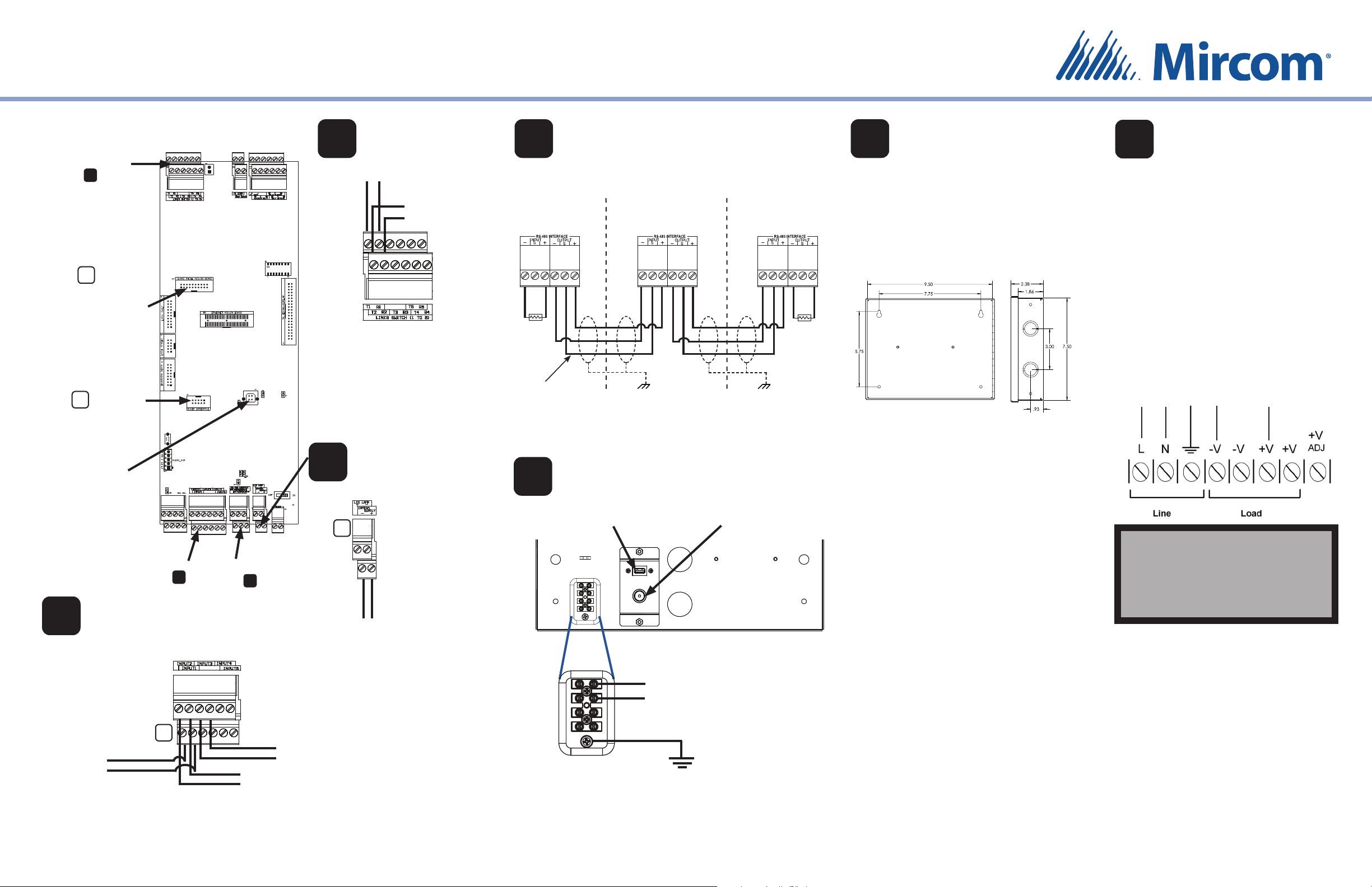
Warning: Turn the power o
before wiring.
Phone Lines:
7
see
P7
Guard
Phone board
connector
TX3-MDM
P4
Modem board
connector
7
Phone Lines
Line 1
TR
T
R
Non-con gurable PBX
systems are not supported.
For more information,
contact Mircom technical
support at 1- 888-647-2665.
Line 2
(optional)
9
Maximum total length: 4000 ft (1219.2 m) for 22 AWG
Use twisted shielded pair. See LT-996 for complete details.
Panel 1
First panel on network
Optional common
reference connection
if available
RS-485
Connect shield to chassis
ground on one panel only
Panel 2
Panel 3
Last panel on network
Connect shield to chassis
ground on one panel only
Mount the TX3-PS24-5A
11
24 VDC, 156 W
12
1. Set the voltage selectable switch on the
Power Supply
Overall dimensions including door:
height: 7 23/32” (196 mm)
width: 9 53/64” (250 mm)
depth: 2 3/8” (60.5 mm)
Knockout dimensions: 1 1/8” (29 mm) and 7/8” (22 mm)
120 Ω 120 Ω
Back View
SideView
2. Connect the load power supply wires
3. Connect the other end of the load power
4. Connect the building power supply
5. Turn the power on by pressing the
Connect the Power
power supply to the appropriate voltage.
The voltage selectable switch can be set
to either 115 V or 230 V.
to the Touch Screen terminal screws as
shown in step 10.
supply wires the Load terminals.
wires to the Line terminals as shown
below.
power button.
To building
power
{
To Touch Screen
{
USB connector:
Connect to computer
for rmware upgrade
and con guration
(maximum length of
USB cable:
8 feet/2.4 m)
Postal Lock:
6
see
RS-485:
9
see
8
Note: Do not use for
any other purpose
TS3
Postal Lock (Input 1)
6
Camera Supply
Fire Alarm Override (Input 2)
Door Contact (Input 3)
22 AWG
TS5
Postal Lock
Warning: Do not attach
the wiring until after the
postal lock is installed.
For more details, see LT-996 and LT-969 on the Mircom website and the USB ash.
Mircom technical support: 1-888-647-2665
Fire
Panel
Door
Contact
Activation of this input
unlocks the main
and auxiliary doors
(Outputs 1 and 2).
Camera Power
Supply (12 VDC)
Activation of this
input relocks the main
door (Output 1).
10
Note: Mircom recommends using a 500 VA
uninterruptible power supply with 15 inch Touch
Screens.
Ground and Power
USB port for
keyboard
Power button
To TX3-PS24-5A 24 VDC
+
power supply
-
Ground
(16 AWG)
Attention: Install the power supply
indoors, and outside the Touch Screen
enclosure.
To surface mount the power supply enclosure:
You need 4 fasteners appropriate for the wall that
you are mounting the enclosure on.
1. Find a suitable location for the power supply
enclosure, such as over a wall stud.
2. Using the enclosure as a template, mark the
two top mounting hole locations. Ensure that
at least one side is over a wall stud.
3. Remove the enclosure and place two wall
fasteners halfway into the marked hole
locations.
4. Place the enclosure onto the fasteners and
lower it so that the fasteners t in the narrow
part of the keyholes.
5. Screw the other two fasteners into the two
remaining holes.
6. Tighten all four fasteners into place.
Note: The enclosure can also be mounted
directly onto the drywall using anchors.
WARNING
To ensure the security of
occupants, change the level 3
passcode from its default setting.
See LT-995 on mircom.com for details.
Mircom
http://www.mircom.com
CANADA - Main O ce
25 Interchange Way
Vaughan, ON L4K 5W3
Tel: (888) 660-4655
(905) 660-4655
International
Tel: (905) 660-4655
© Mircom 2020
Printed in Canada
Subject to change without prior notice
LT-6678 rev 1
 Loading...