

Page 1
© Mircom 2015
Printed in Canada
Subject to change without prior notice
LT-6125 rev 0
For more details, see LT-996 and LT-969 on the Mircom website and the USB ash.
Mircom technical support: 1-888-647-2665
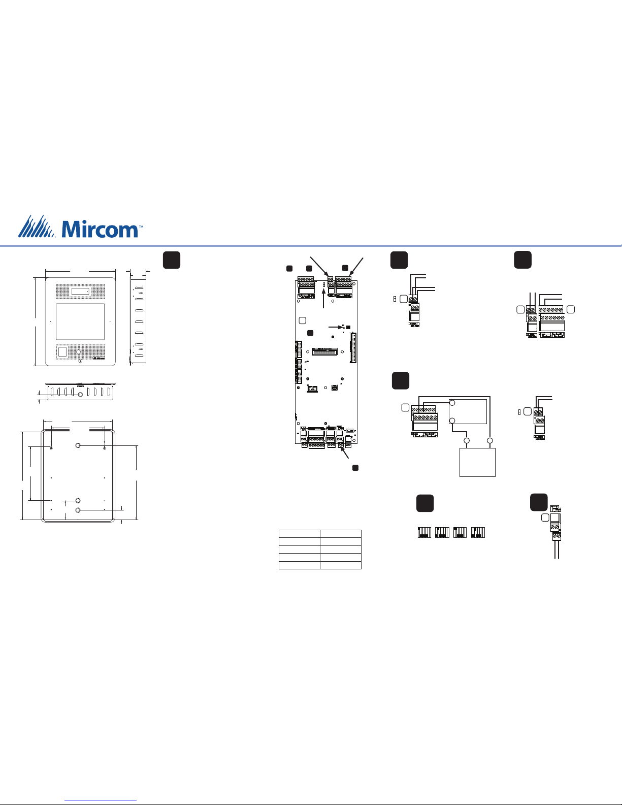
ASSEMBLING TX3-TOUCH-F15-B
AC or DC Door
Strikes:
see and
1
Auxiliary Door
Strike:
see
NO
NC
Jumper JW8
2 3
4
AC Door Strike or
Magnetic Lock
AC Power Supply
for Door Strike
AC Door Strike or Maglock
18 AWG
For a door strike: connect the
jumper wire to the top pin of
jumper JW8 (normally open).
For a maglock: connect the
jumper wire to the bottom
pin of jumper JW8 (normally
closed).
TS8
Jumper JW8
NO
NC
2
Door Strike
Note: Most door
strikes are nonpolarity.
Power Supply
Note: If AC power
supply is used,
polarity does not
apply.
Auxiliary Door
(Output 2)
18 AWG
TS9
+
-
+
-
4
Warning: Turn the power
o before wiring.
Install all power supplies outside the enclosure.
Wiring Requirements
Unless speci ed other wise, all wiring is a maximum
length of 1000 ft (304.8 m).
RS-485: 22 AWG twisted pair, maximum length: 4000
ft (1219.2 m). Mircom recommends shielded cable.
Door Strike: The door strike power supply depends
on the door strike power requirements.
AC or DC Power
Supply for Door
Strike
DC Output
Door Strike or
Magnetic Lock
DC Door Strike
(Output 1)
18 AWG
TS8
TS9
3
The maximum supply for the AC or DC
Power Supply for Door Strike must not
exceed:
28 VAC / 1 A max
30 VDC / 1 A max
Trigger for door operator
Jumper JW8 controls
whether the contact
is normally open or
normally closed.
Alternative Wiring
for Dry Contact
TS8
Jumper JW8
NO
NC
Contact ratings for outputs 2-4:
125 VAC / 2 A
30 VDC / 1 A
DIP Switch Settings
for RS-485 Address
Address 1
ON
OFF
Address 4Address 2
Address 3
18181818
5
Each Touch Screen must have a unique RS-485
address.
Use DIP switches 1-6 to set the RS-485 network
address. See LT-969 for details.
Camera Power
Supply (12 VDC)
Camera Supply
TS3
6
22”
(559 mm)
17 1/2”
(445 mm)
1 1/4”
(32 mm)
3 51/64”
(96 mm)
3 31/32”
(101 mm)
16 19⁄64”
(414 mm)
20 3/4”
(527 mm)
2 7/32”
(57 mm)
4 1/2”
(114 mm)
17 9⁄16”
(446 mm)
12 3/4”
(324 mm)
12 19⁄32”
(320 mm)
SW1
Mount the
Enclosure
1
The enclosure mounts on the wall. Mount the
enclosure right-side up (the Mircom logo on the
door is in the lower right corner).
You need:
4 fasteners appropriate for the wall that you are
mounting the enclosure on.
1. Find a suitable location for the enclosure. You can
mount the enclosure using the keyholes on the
back, or the knockouts on the side, or both.
2. Trace an opening in the wall for the enclosure
with one side aligned with a wall stud.
2. Cut an opening in the wall 3/32” (3 mm) larger
than the tracing, ensuring that one side is
aligned with the wall stud or supporting
structure.
3. Insert the enclosure into the wall cutout, and
using the side of the enclosure as a template
mark the hole mounting locations (either
keyholes or knockouts or both).
4. If you are using the keyholes, remove the
enclosure and place 2 fasteners halfway into the
wall into the two top keyhole locations.
5. Place the enclosure onto the top fasteners, then
lower it so that the fasteners t in the narrow
part of the keyholes.
6. Screw the other fasteners into the remaining
holes.
7. Tighten all fasteners into place.
Camera Supply:
see
6
DIP Switches:
see
5
Gauge Distance
16 125 ft (38.1 m)
14 200 ft (60.96 m)
12 320 ft (97.536 m)
10 500 ft (152.4 m)
Maximum Power Supply Wire Distances
Page 2
For more details, see LT-996 and LT-969 on the Mircom website and the USB ash.
Mircom technical support: 1-888-647-2665
ASSEMBLING TX3-TOUCH-F15-B
© Mircom 2015
Printed in Canada
Subject to change without prior notice
LT-6125 rev 0
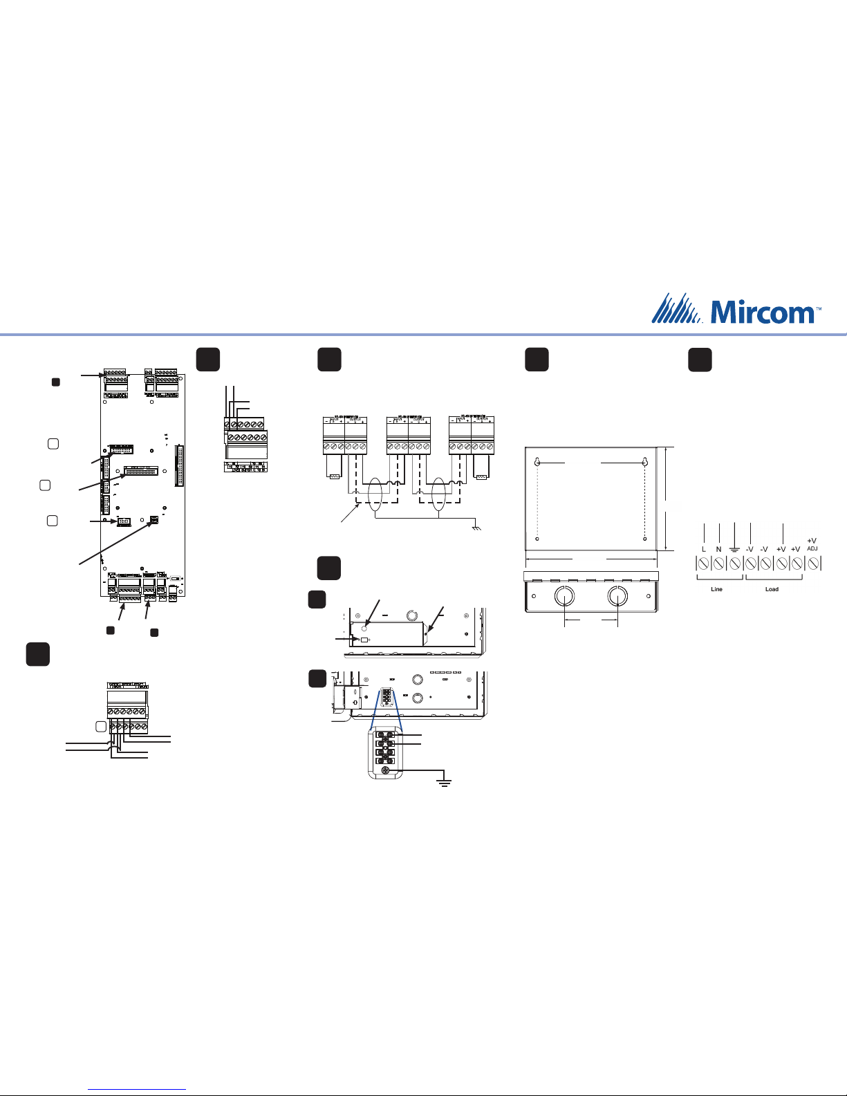
Warning: Turn the power o
before wiring.
Line 1
Phone Lines
Non-con gurable PBX
systems are not supported.
For more information,
contact Mircom technical
support at 1- 888-647-2665.
Line 2
(optional)
TR
T
R
8
Postal Lock
Postal Lock (Input 1)
Fire Alarm Override (Input 2)
Door Contact (Input 3)
22 AWG
Warning: Do not attach
the wiring until after the
postal lock is installed.
Fire
Panel
Door
Contact
TS5
7
Activation of this
input relocks the main
door (Output 1).
Activation of this input
unlocks the main
and auxiliary doors
(Outputs 1 and 2).
Postal Lock:
see
RS-485:
see
Phone Lines:
see
USB connector:
Connect to computer
for rmware upgrade
and con guration
(maximum length of
USB cable:
8 feet/2.4 m)
Guard
Phone board
connector
TX3-MDM
Modem board
connector
P7
P4
8
7
9
TX3-IP Module
Connection
P5
22 AWG twisted pair, maximum length: 4000 ft (1219.2 m)
Mircom recommends shielded cable
RS-485
9
120 Ω
120 Ω
Panel 3
Last panel on network
Panel 2Panel 1
First panel on network
Optional common
reference connection
if available
Connect shield to chassis
ground on one panel only
Ground and Power
10
Remove nut and
open cover to
access ground and
power terminals
To MD-990 24 VDC
power supply
Ground
(16 AWG)
To surface mount the power supply enclosure:
1. Find a suitable location for the power supply
enclosure, such as over a wall stud.
2. Using the power supply enclosure as a template,
mark the back mounting hole locations. Ensure
that at least one side is over a wall stud.
3. Remove the power supply enclosure and place
the top two screws halfway into the marked hole
locations and wall stud.
4. Place the power supply enclosure onto the two
screws.
5. Screw the other two screws into the remaining
holes.
6. Tighten all four screws into place.
Note: The enclosure can also be mounted directly
onto the drywall using anchors.
To building
power
To Touch Screen
{
{
1. Connect the MD-990 load power supply
wires to the Touch Screen terminal
screws as shown in step 10.
2. Connect the building power supply
wires to the MD-990 line terminal screws
as shown below.
3. Connect the other end of the building
power supply wires the line voltage
terminals.
4. Turn the power on by pressing the
power button.
Mount the MD-990
24 VDC, 156 W
Power Supply
11
12
Connect the Power
Overall dimensions including door:
height: 7 23/32” (196 mm)
width: 9 53/64” (250 mm)
depth: 2 37/64” (66 mm)
Knockout dimensions: 1 1/8” (29 mm) and 7/8” (22 mm)
9 1/5” (241 mm)
7 1/5”
(191 mm)
7 3/4” (197 mm)
3” (76 mm)
A
B
USB port for
keyboard
Power button
Mircom
CANADA - Main O ce
25 Interchange Way
Vaughan, ON L4K 5W3
Tel: (888) 660-4655
(905) 660-4655
Fax: (905) 660-4113
U.S.A
4575 Witmer Industrial Estates
Niagara Falls, NY 14305
Tel: (888) 660-4655
(905) 660-4655
Fax: (905) 660-4113
TECHNICAL SUPPORT
North America
Tel: (888) Mircom5
(888) 647-2665
International Tel:
(905) 647-2665
+
-
 Loading...