

Mircom TX3-CX-1NP, TX3-P300-HA Installation Manuals
TX3-CX-1NP Installation
Installing on a telephone entry unit
Installing on a Touch Screen
These instructions explain how to install the TX3-CX-1NP and the TX3-P300-HA card reader
in the following TX3 units:
TX3-TOUCH-F15-B/C TX3-200-8U-B/C TX3-1000-8U-B/C TX3-2000-8U-B/C
TX3-TOUCH-S15-B/C TX3-200-8C-B/C TX3-1000-8C-B/C TX3-2000-8C-B/C
TX3-TOUCH-F22(-C) TX3-TOUCH-S22(-C)
These units include 2 #6-32 x 1/2" screws for attaching the TX3-P300-HA card reader to the
inside of the door.
A. Contents of Kit
Qty 1... TX3-CX-1NP
Qty 2... Nuts for attaching TX3-CX-1NP to the TX3 unit
Qty 1... USB cable for programming TX3-CX-1NP
Qty 1... USB flash containing TX3 software and manuals
B. Mount TX3-CX-1NP
TX3-CX-1NP Installation
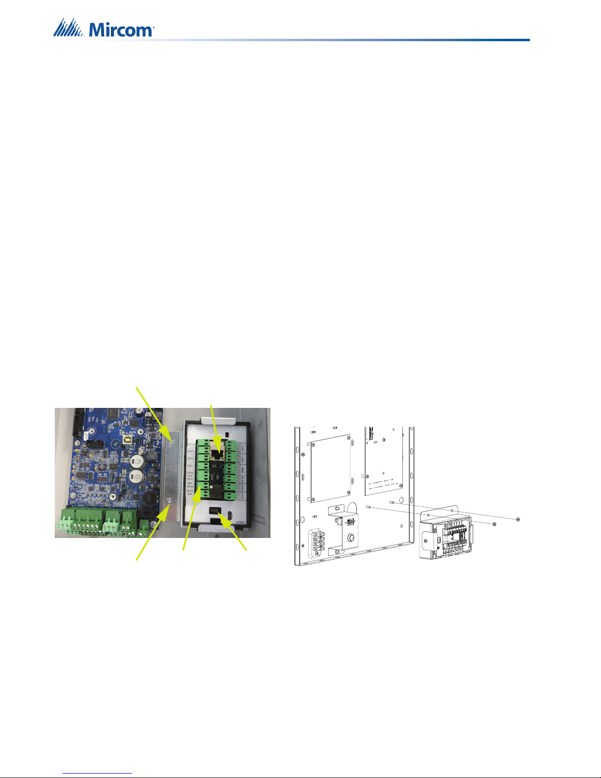
1. Mount TX3-CX-1NP on the two posts as shown in Figure 1.
2. Secure it with the provided nuts.
Nut
Nut
Figure 1 Mount TX3-CX-1NP
RJ45 connector for
Internet communication
and Power over Ethernet
Card reader
connections
DIP switches
C. Mount the TX3-P300-HA Card Reader
• Secure the card reader to the plastic bracket on the inside of the door with the 2 #6-32 x 1/2"
screws that are included with the TX3 unit.
Note: Do not use the cover that is included with the reader.
Note: Install the reader with the LED facing out.
1
LT-5997 Rev 3 January 2018
Subject to change without notice. See http://www.mircom.com for the latest information
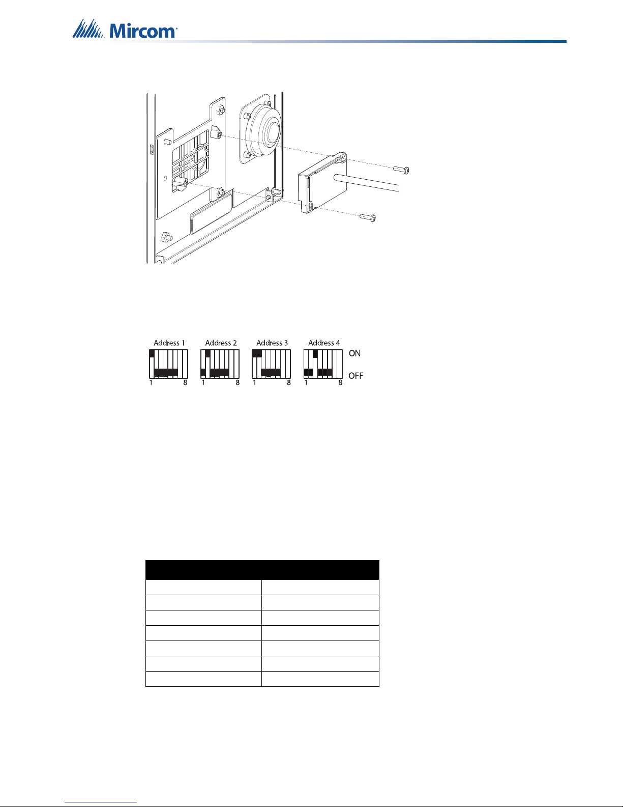
Figure 2 Install the card reader with the LED facing out
D. Set the RS-485 Address
• Use DIP switches 1-6 (shown in Figure 1) to set the RS-485 network address.
TX3-CX-1NP Installation
Figure 3 Set the RS-485 address
Note: You must set the RS-485 address even if you are not using RS-485.
• Keep DIP switch 7 off.
• Set DIP switch 8 off to get an IP address from the DCHP server.
• Set DIP switch 8 on to set a fixed IP address using the TX3 Configurator software.
For more information and the complete list of RS-485 addresses, see LT-980, the TX3 Card
Access System Manual, on the Mircom website (www.mircom.com) or the USB flash.
E. Connect the Card Reader
Table 1: Connections for the TX3-P300-HA reader
Color of Reader Wire Terminal on TX3-CX-1NP
Green DATA0
Black GND
White DATA1
Blue BEEP
Brown LED (R)
Orange LED (G)
Red PWR
Card reader requirements
Card readers must meet the following minimum requirements in order to be compatible with
Mircom’s Card Access System:
• 26 bit standard SIA protocol
LT-5997 Rev 3 January 2018
Subject to change without notice. See http://www.mircom.com for the latest information
2
 Loading...