

Page 1
TX3 Series
TELEPHONE ACCESS SYSTEMS
Programming Manual
Version 2.4 Telephone Access System Programming Manual 1
LT-979 Copyright October 2016
Page 2

Copyright October 2016 Mircom Inc.
All rights reserved.
Telephone Access System Programming Manual v. 2.4 for Windows 2000/NT/XP®.
This manual, as well as the software described in it, is provided under licence or other agreements
and may be used or copied only in accordance with the terms of such license. The content of this
manual is furnished for informational use only. It is subject to change without notice, and should not
be construed as a commitment by Mircom. Mircom assumes no responsibility or liability for any errors
or inaccuracies that appear in this book.
Except as permitted by such license, no part of this publication may be reproduced, stored in a
retrieval system, transmitted in any form by means electronic, mechanical, using any recorded
media, or any other format without the prior written p ermission of Mircom.
Microsoft, MS-DOS, Windows, and Windows 2000/NT/XP are either registered trademarks or
trademarks of Microsoft Corporation in the United States and/or other countrie s.
Mircom
25 Interchange Way
Vaughan, Ontario
L4K 5W3
905.660.4655
Fax:905.660.4113
2 Mircom Version 2.4
LT-979 Copyright October 2016
Page 3

Contents
1 Introduction 4
1.1 TX3 Systems 5
1.2 Features 5
1.3 Warranty and Special Notices 6
1.4 About This Manual 6
1.5 Contact Us 8
1.6 Viewing Resident List 9
2 Configuration 10
2.1 Keypad Navigation 11
2.2 Beginning Configuration 11
2.3 Viewing Configuration Information 12
2.4 Accessing the Operation Menu 13
2.5 Configuration Menu 15
2.6 System Option 15
2.7 Database Menu 32
2.8 Schedule Menu 42
2.9 Holidays Menu 43
2.10 Factory Default 44
2.11 Input/Output 45
2.12 Correlations 47
2.13 Changing Passcodes 49
2.14 Test LCD 50
Version 2.4 Telephone Access System Programming Manual 3
LT-979 Copyright 2016
Page 4

1 Introduction
This manual provides you with detailed instructions on how to configure the TX3
Telephone Access System from the main entry panel keypad.
This manual must be read in its entirety before beginning the configuration.
Configuration must be performed by a qualified technician and must adhere to
the standards and special notices set by the local regulatory bodies.
Note: Mircom periodically updates panel firmware and Configurator
Software to add features and correct any minor inconsistencies.
For information about the latest firmware or software visit the
Mircom website at www.mircom.com.
For warranty and special notices information see the Warranty and Special
Notices chapter on page 51.
This manual explains
• The TX3 Telephone Access System
• How to configure the TX3 Telephone Access System
4 Telephone Access System Programming Manual Version 2.4
LT-979 Copyright 2016
Page 5

1.1 TX3 Systems
The Mircom's TX3 series of telephone access systems provide high quality twoway communication between residents and their visitors in a multi-unit dwelling
establishment.
The basic TX3 system consists of the TX3 Entry Panel and depending on the
application, may be integrated with a combination of Mircom Elevator
Restriction Units and Card Access Units. All access systems may be networked
together using an RS-485 connection.
The TX3 system is capable of providing ADC or NSL telephone access from a
single panel or from a networked system. The TX3 system also may consist of
one or more access systems networked together using an RS-485 connection.
The access system can be configured as an autodialer controller (ADC) or as a no
subscriber line (NSL) system. Both system setups can be configured for multiple
entrances with independent doors and control devices such as electric door locks,
cameras, and garage doors.
1.1.1 ADC and NSL Capability
Introduction
A single TX3 Entry Panel supports full ADC and NSL telephone connectivity.
An ADC connection requires a dedicated subscriber telephone line service
connected to an outside telephone line. This mode lets the visitor call the tenant
and access their voice mail.
An NSL connection uses the existing building telephone lines for
communication and does not require a separate telephone line. This system may
consist of one or more entry panels connected to TX3-NSL-8M NSL Units,
typically located in the electrical/telephone room of a building. The NSL units
intercept all telephone lines into the building’s suites if the lines are not in use.
This mode lets the visitor call the tenant and access their voice mail and call
waiting.
1.1.2 Elevator Restriction Units
The TX3-ER-8 Elevator Restriction Unit limits building accessibility by
granting visitor access only to the destination floor.
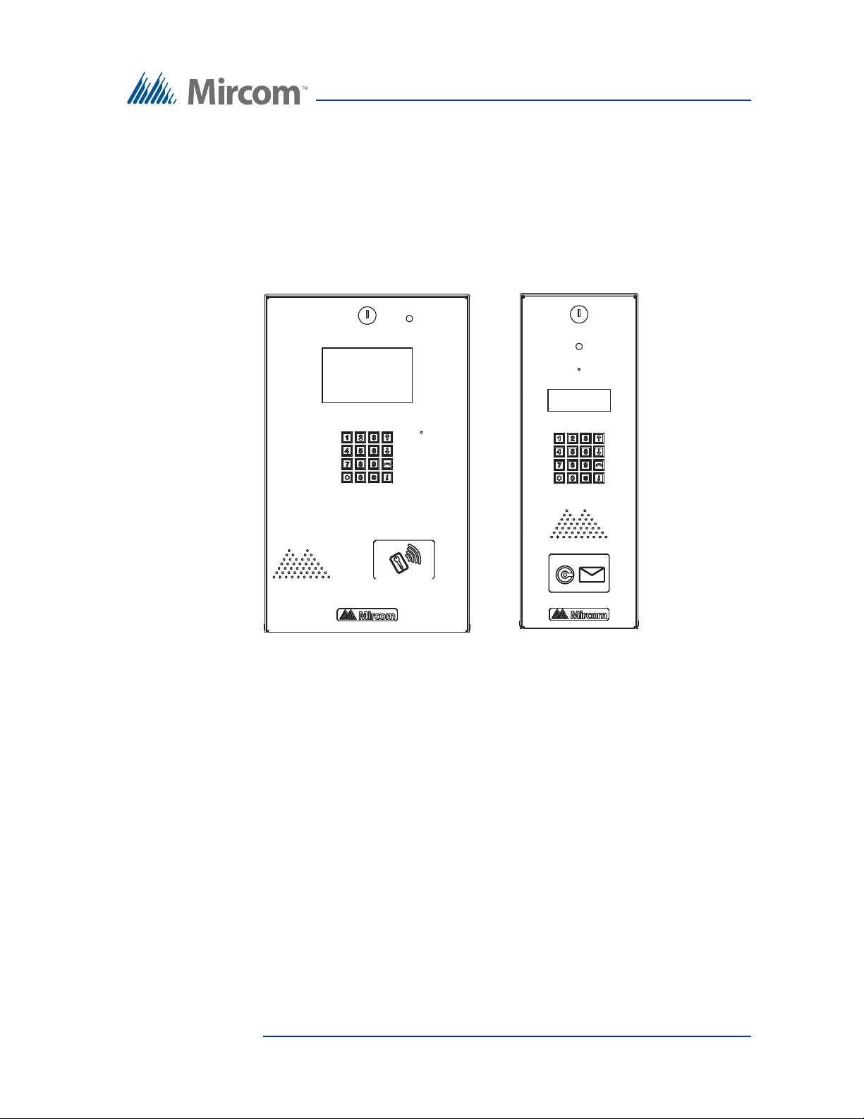
1.2 Features
Features of the TX3 series include:
• Stainless steel front panel
• Universal Series enclosure with a built-in rain hood
• Large scrolling 8 x 20 LCD display that eliminates the need for an external
directory
Version 2.4 Telephone Access System Programming Manual 5
LT-979 Copyright 2016
Page 6

Introduction
• Back-lit 16 digit keypad with dedicated operational buttons for Page Up,
Page Down, Call and Info
• Provisions for postal lock and camera
• Multilingual Display and Voice Greeting (English, French-Canadian and
Spanish) that provides instructions on how to use the entry panel
• Concierge/Security Desk/Guard Phone capability
• Card Access Interface
• Supports both Auto Dialer (ADC) and NSL (no phone bill)
• Ability to network panels together (peer-to-peer)
• Hands free, full duplex communication
• Flexible one to four digit resident dial codes
• Dials up to 18 digit telephone numbers
• System can be configured locally using the keypad or a computer with the
TX3 configuration software
• Upload/download configuration files without taking the whole system offline
• Programming from one location
• Records a maximum of 5000 event logs
• Elevator restriction capability
• Schedule based call restrictions provide more security and flexibility
• Capability of one person testing of the NSL controller without using the
lobby panel
• Industry Canada and F.C.C. approved
1.3 Warranty and S pecial Notices
Mircom values your business and always attempts to provide you with the very
best service.
Please see the Warranty and Special Notices chapter on page 51 for information
about the warranty and special notices about equipment use.
1.4 About This Manual
This manual provides comprehensive information on the configuration of the
TX3 Series Telephone Access System. Tasks are described in the order that they
are likely to be performed.
6 Telephone Access System Programming Manual Version 2.4
LT-979 Copyright 2016
Page 7

This manual applies to the following models:
• TX3-120U and TX3-120U-A
• TX3-200-8U, TX3-200-8U-A and TX3-200-8U-B
• TX3-1000-8U, TX3-1000-8U-A and TX3-1000-8U-B
• TX3-2000-8U, TX3-2000-8U-A and TX3-2000-8U-B
• TX3-200-4U-A and TX3-200-4U-B
• TX3-1000-4U-A and TX3-1000-4U-B
• TX3-2000-4U-A and TX3-2000-4U-B
• TX3-120C-A
• TX3-200-8C-A and TX3-200-8C-B
• TX3-1000-8C-A and TX3-1000-8C-B
• TX3-2000-8C-A and TX3-2000-8C-B
• TX3-200-8CH-A
• TX3-1000-8CH-A
Introduction
• TX3-2000-8CH-A
• TX3-2000-8K-A
1.4.1 Version Control
The version number appears on the front cover and changes whenever there is a
major or minor update to any part of the system regarding operation or
configuration.
The following convention indicates major or minor changes:
Initial release. Version 1.00.0
Major change. Version 1.01.0
Minor change. Version 1.01.1
1.4.2 Additional Documentation
For additional documentation, see the following Mircom literature:
• TX3-CX Touch Screen Administrators Guide LT-995
• TX3-CX Card Access System Installation and Operation Manual LT-980
• TX3 Telephone Access System User’s Guide LT-968
• TX3 Two Door Card Access System Kit Catalogue Number 6531
• TX3 Series Elevator Restriction Accessories Catalogue Number 6532
Version 2.4 Telephone Access System Programming Manual 7
LT-979 Copyright 2016
Page 8
1.5 Contact Us
You can contact us from Monday to Friday 8:00 A.M. to 5:00 P.M. E.S.T.
1.5.1 General Inquiries
Toll Free: 1-888-660-4655
Local: 905-660-4655
Introduction
1.5.2 Customer Service
Toll Free: 1-888-MIRCOM5
Local: 905-695-3535
Local Fax: 905-660-4113
Toll-Free Fax: 1-888-660-4113
1.5.3 Technical Support
For technical support contact Mircom’s Technical Support Department between
8 A.M. and 5 P.M. (EST) Monday through Friday, excluding holidays.
Toll Free: 1-888-MIRCOM5
Local: 905-695-3535
Local Phone: 905-660-4655
Toll Free Phone: 1-888-660-4655
Email: techsupport@mircom.com
1.5.4 Website
www.mircom.com
1.5.5 Email
mail@mircom.com
8 Telephone Access System Programming Manual Version 2.4
LT-979 Copyright 2016
Page 9

1.6 Viewing Resident List
The TX3 Entry Panel LCD shows a scrollable view of the resident names and dial
codes. The LCD comes in a four or eight line LCD handset version. A paper
version of the resident list is also available.
To view the resident list
1. Press the up or down arrow keys on the Entry Panel keypad to scroll
through the list line by line.
or
To view the resident list page by page use the star key to scroll page up and
number key to scroll page down.
2. Key in the dial code associated with the resident you wish to speak to or
press the Telephone Key when the cursor is on the resident’s name. For the
handset version, first pick up the phone and then key in the dial code or
press the Telephone Key.
Introduction
3. Once the resident grants entry permission, the door unlocks. For the
handset version, hang up the phone and proceed through the door.
Version 2.4 Telephone Access System Programming Manual 9
LT-979 Copyright 2016
Page 10

2 Configuration
This chapter provides detailed information about the TX3 Telephone Access
System configurable functions.
This chapter explains
• How to Use the TX3 Telephone Access System
• Access Levels
• Viewing Configuration Information
• Entering Configuration Mode
• Keypad Navigation
• Exiting Configuration Mode
• Configuration Menu
• Operation Menu
• Database Menu
• Adding a New Record
• System Option
• Schedule Menu
• Factory Default
• Input/Output
• Correlations
10 Telephone Access System Programming Manual Version 2.4
LT-979 Copyright 2016
Page 11
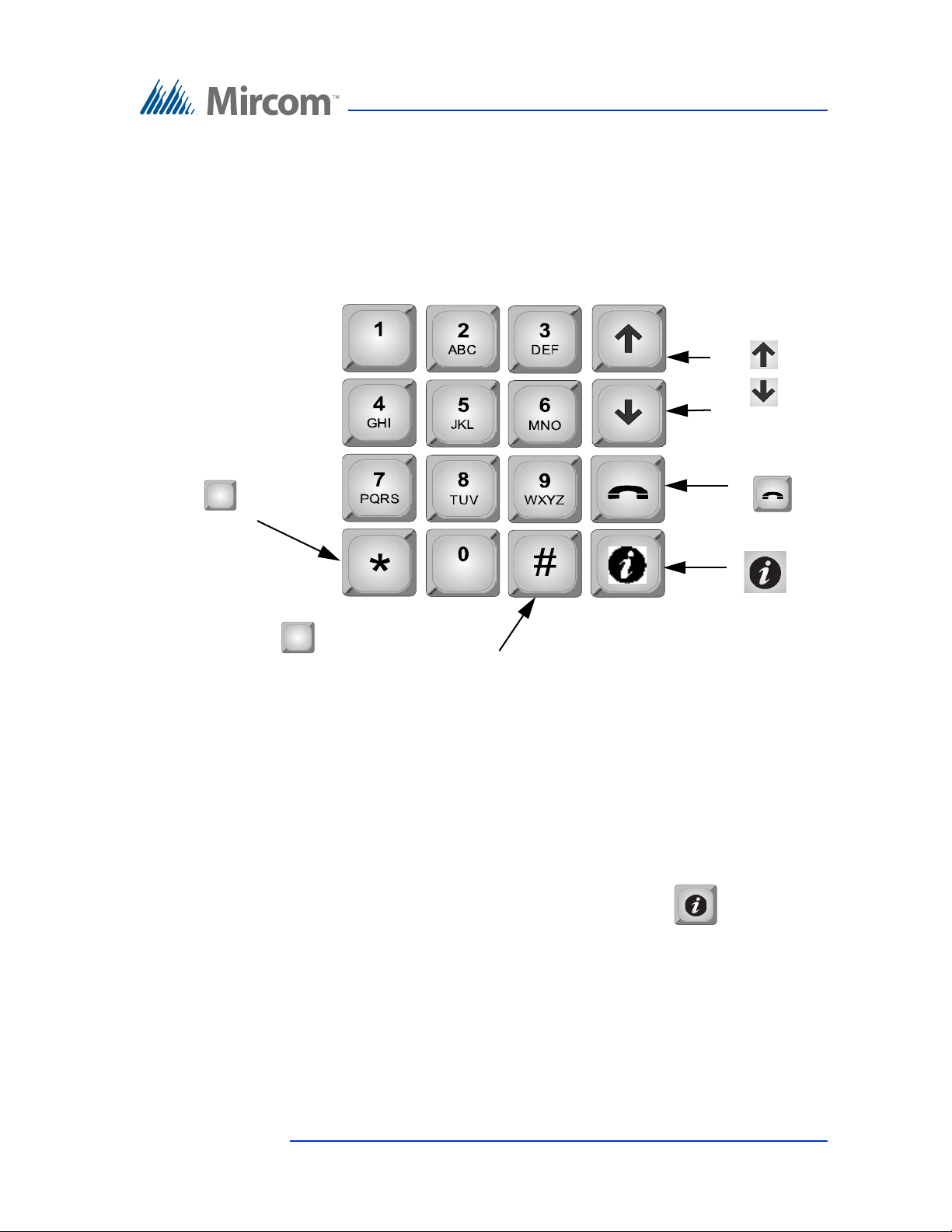
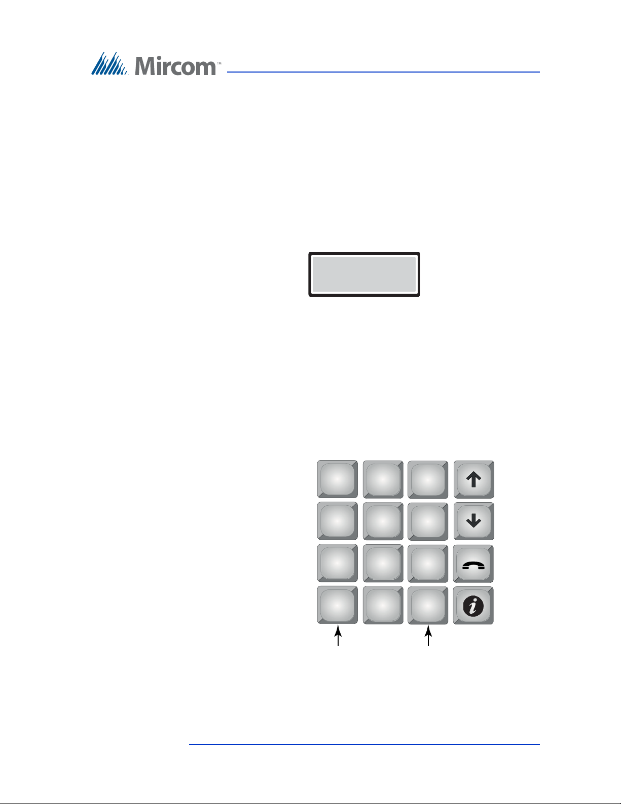
2.1 Keypad Navigation
In configuration
mode
Press to move
left.
*
In configuration
mode
Press to scroll up
Press to scroll
down.
Press to cancel
the selection or exit
Press to enter
and confirm selection.
Press to move right for checking
and un-checking the check box
Figure 1 shows how to use the keypad when in CONFIGURATION MODE.
Note that the keypad buttons can have different functions when creating resident
entries. Refer to 2.7.1 Adding a New Record and Table 1: List of Screens for
more information.
Configuration
2.1.1 Exiting Configuration Mode
2.2 Beginning Configuration
#
Figure 1. Keypad Navigation
You can exit the configuration mode at any time.
To exit configuration mod e
1. To exit the configuration mode, press the info key to return to the
previous menu.
To configure the Telephone Access panel, you must first enter the configuration
mode.
Version 2.4 Telephone Access System Programming Manual 11
LT-979 Copyright 2016
Page 12
Configuration
Main Menu
1 Configuration
2 Operation
3. View Cfg Info
Enter the Passcode
[ _ _ _ _ _ _ _ _ _ ]
Main Menu
1. Configuration
2. Operation
3. View CFG Info
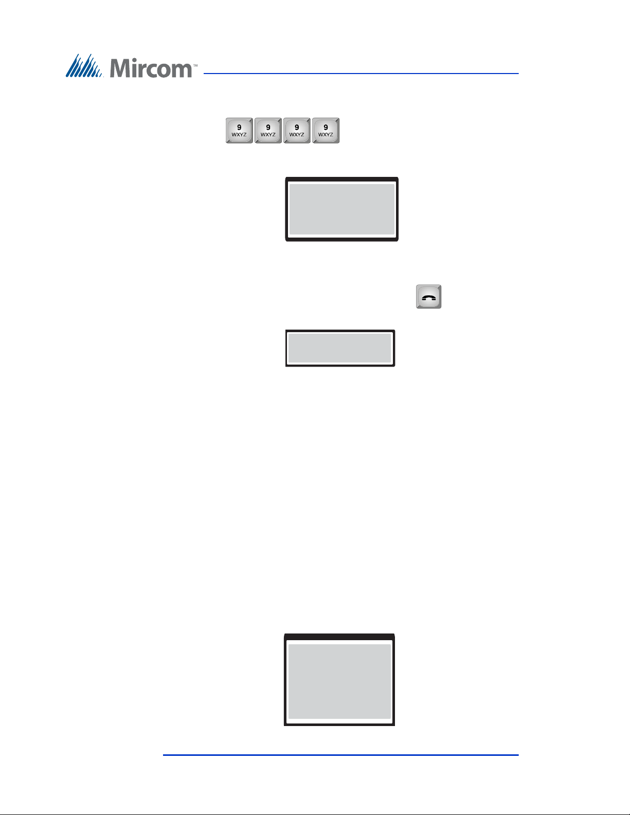
To enter configuration mode
1. Press . The main menu appears with three
choices; the Configuration Menu, Operation Menu and the View
Configuration Information.
To access the Operation menu see paragraph 2.4.
To access the View Configuration Information menu see paragraph 2.3.
2. Select Configuration and press the telephone key . The passcode
message appears.
3. Enter your passcode.
or
If you have not set a personal passcode, press 3 3 3 3. This number is the
four-digit factory default. You are now in configuration mode.
To continue with configuration see paragraph 2.5.
2.3 Viewing Configuration Information
To view configuration information, you must first enter the configuration mode.
To select viewing mode
1. Press 9 9 9 9. The Main Menu appears. You may need to scroll up or
down to view the entire selection.
12 Telephone Access System Programming Manual Version 2.4
LT-979 Copyright 2016
Page 13

2. Press the (scroll down) to “View Cfg Info”.
Main Menu
1. Configuration
2. Operation
3. View CFG Info
Operation Menu
1 View logs
2 Delete logs
3 Set time & date
Logging data not
present
3. Press the telephone key to view the configuration information. The
system configuration information appears.
4. Press the info key to return to the previous menu.
2.4 Accessing the Operation Menu
The Operation Menu lets you view logs, delete logs and set the time & date.
To access the operation menu
1. Press 9 9 9 9. The configuration information appears.
Configuration
2. Press the (scroll down) to “Operation”.
3. Press the telephone key. The “Operation” menu appears.
To view logs
1. Press the arrow key to scroll to “View Logs” and press the enter
(telephone) key. The system information appears.
If you have just installed the system, following message appears.
Version 2.4 Telephone Access System Programming Manual 13
LT-979 Copyright 2016
Page 14
Configuration
User log info
Log: 190 of 5000
Event: Call Connect
Acc pt: N/A
Acc Code: D20
Jan 15 2010
12:22 pm
Delete Log
User log (s)
System log (s)
All log (s)
2. If recent events have occurred, such as, entering of dial codes and the
opening of the main door, this information appears along with the date and
time as follows.
The first four digits represent the index of logged events in sequence
from 1 (0001) up to 5000.
The following letter “D” indicates that the preceding number was a dial
code (D = dial code, K = keyless code).
The term “Acc:” represents the word “access”. The term “Yes” indicates
that access was granted.
3. Press info key to return to previous menu.
To delete logs
1. Press the arrow key to scroll to “Delete Logs” and press the telephone key.
The “Delete Logs” selection appears.
2. Use the up and down arrow keys to select the log and press the telephone
(enter) key to delete.
3. Press info key to return to previous menu.
14 Telephone Access System Programming Manual Version 2.4
LT-979 Copyright 2016
Page 15
To set time & date
Set Time/Date
Apr 14, 2009 03:23 PM
1. Press the arrow key to scroll to “Set Time & Day” and press the telephone
key. The time and day information appears.
2. Use the up and down arrow keys to set the time and day.
3. Press info key to return to previous menu.
2.5 Configuration Menu
The Configuration Menu consists of the following configurable items.
• System Option
• Database
Configuration
• Schedules
•Holidays
• Factory Default
• Input/Output
•Correlation
• Change Passcode
• Test LCD
For a description on how to configure these items see paragraphs 2.6 to 2.14.
2.6 System Option
Selecting “System Option” from the Configuration Menu gives you the
following configuration options:
• Tone/Pulse mode
• Line Type
• Main Door DTMF
• Aux Door DTMF
Version 2.4 Telephone Access System Programming Manual 15
LT-979 Copyright 2016
• Main door timer
• Aux door timer
Page 16

• Talk timer
• Language
• Welcome Message
• Guard Phone
•Calling Sch
• Unlock Schedule
• Keycode Sch
•Call Wait Key
• Keypad Active
• No of rings
• Postal usage
• Scroll speed
• Day light saving
• Clock adjustment
Configuration
• Elevator Rest Timer
• Speaker volume
• MIC volume
• Select Font (only available on 8-line display)
• Voice Help Option
• Auto Unlock Schedule
• DTMF Sensitivity
• Handset
For a description on how to configure these items see paragraphs 2.6.1 to 2.6.28
2.6.1 Tone/Pulse mode
Note: Although this option appears on the front panel, it is not
configurable. The telephone always operates in tone mode. Pulse
dialing is not available.
To access the Tone/Pulse optio n screen
1. Press the arrow key to scroll to “Tone/Pulse mode” and press the telephone
key. The tone/pulse selection appears.
2. Press the info key to return to the previous menu.
16 Telephone Access System Programming Manual Version 2.4
LT-979 Copyright 2016
Page 17
2.6.2 Line Type
Line Type
L-1
L-2
L-3
Select Line T ype
[ x ] ADC Type
[ ] NSL Type
[ ] Unused
Main Door DTMF
[ x ] ‘9’
[ ] ‘0’
The Line Type function defines each of the 5 telephone lines as ADC, NSL or not
used. By default is line 1 is ADC and lines 2 to 5 as unused.
To define the line type operation
1. Press the arrow key to scroll to “Line Type” and press the telephone key.
2. Using the down arrow key to select L-1, and press the telephone (enter)
Configuration
The line selection appears.
key. The line type selection appears.
3. Use the ‘*” and or “#” key to make a selection.
4. Press the telephone key to enter the selection.
5. Press the info key to return to the previous menu.
2.6.3 Main Door DTMF
The Main Door DTMF function defines the key the resident presses to open the
main door. The default key is 9.
To define the Main Door DTMF key
1. Press the arrow key to scroll to “Main Door DTMF” and press the
telephone key. The Main Door DTMF selection appears.
2. Use the up or down key to move to the key number.
Version 2.4 Telephone Access System Programming Manual 17
LT-979 Copyright 2016
Page 18

3. Use the * key to select the number and the telephone (enter) key to confirm
Aux Door DTMF
[ ] ‘6’
[ ] ‘7’
[ ] ‘9’
the DTMF code. Valid numbers are 1 to 9, * or #.
Note: Do not select 4 (this is used to refuse entry or disconnect) and do not
4. Press the info key to return to the configuration menu.
5. Press the info key to return to the previous menu.
2.6.4 Aux Door DTMF
The Aux Door DTMF function defines the key the resident presses to open the
auxiliary door. The default key is 6.
To define the Aux Door DTMF key
Configuration
select the number that you are using for Call Wait Key (see 2.6.14
Call Wait Key on page 24).
1. Press the arrow key to scroll to “Aux Door DTMF” and press the telephone
key. The Aux Door DTMF selection appears.
2. Use the up or down key to move to the key number.
3. Use the * key to select the number and the telephone (enter) key to confirm
the DTMF code. Valid numbers are 1 to 9, * or #.
Note: Do not select 4 (this is used to refuse entry or disconnect) and do not
select the number that you are using for Call Wait Key (see 2.6.14
Call Wait Key on page 24).
4. Press the info key to return to the previous menu.
2.6.5 Main Door Timer
The Main Door Timer function defines the length of time that the main door stays
unlocked after the resident opens the main door using the telephone keypad. The
default is 10 seconds.
18 Telephone Access System Programming Manual Version 2.4
LT-979 Copyright 2016
Page 19

To set the Main Door Timer
Main Door Timer
[ 010 ]
Auxiliary Door Timer
[ 010 ]
1. Press the arrow key to scroll to “Main Door Timer” and press the telephone
key. The Main Door Timer selection entry appears.
2. Use the up or down keys to select the number of seconds. Valid
programmable time is 1 to 60 seconds.
3. Press the info key to return to the previous menu.
2.6.6 Aux Door Timer
The Auxiliary Door Timer function defines the length of time that the auxiliary
door stays unlocked after the resident opens the auxiliary door using the
telephone keypad. The default is 10 seconds.
Configuration
To set the Auxiliary Door Timer
1. Press the arrow key to scroll to auxiliary “Door Timer” and press the
2. Use the up or down keys to select the number of seconds. Valid
3. Press the info key to return to the previous menu.
2.6.7 Talk Timer
The Talk Timer function defines the length of time that a visitor may be on the
telephone with a resident. The default is 60 seconds.
telephone key. The Auxiliary Door Timer selection entry appears.
programmable time is 1 to 60 seconds.
Version 2.4 Telephone Access System Programming Manual 19
LT-979 Copyright 2016
Page 20
To set the Talk Timer
T alk Timer
[ 060 ]
Language
[ x ] English
[ ] French
[ ] Spanish
1. Press the arrow key to scroll to “Talk Timer” and press the telephone key.
2. Use the up or down keys to select the number of seconds. Valid time is
3. Press the info key to return to the previous menu.
2.6.8 Language
The default language is English. Selecting Multi Language makes the opening
screen flip through messages in English, French, and Spanish. Once a key is
pressed, the language that is displayed on the screen at that moment will be used
for the rest of the messages.
Configuration
The Talk Timer selection entry appears.
from 10 to 300 seconds.
To select a language
1. Press the arrow key to scroll to “Language” and press the telephone (enter)
key. The language selection appears.
2. Press the info key to return to the previous menu.
2.6.9 Welcome Message
The Welcome Message function lets you change the welcome message on the
front of the TX3 Entry Control Panel.
20 Telephone Access System Programming Manual Version 2.4
LT-979 Copyright 2016
Page 21
Configuration
Enter Msg Line - 1
MIRCOM TX3 #1
Guard Phone
[ ] Guard Phone
[ x ] No Guard Phone
To change the welcome mess age
1. Press the arrow key to scroll to “Welcome Message” and press the
telephone (enter) key. The welcome message appears.
2. Press the up arrow key to scroll to the next message line (Line-2) and scroll
up again for next message (Line-3).
3. Edit each message.
Press the 1 key 9 times to get an asterisk (*).
4. Press the telephone (enter) key to accept.
5. Press info key to return to previous menu.
2.6.10 Guard Phone
The Guard phone is an optional auxiliary phone on the lobby control unit that lets
you place calls to residents using their dial code.
To enable the guard phone
1. Press the arrow key to scroll to “Guard Phone” and press the telephone
(enter) key. The Guard Phone selection appears.
2. Press the up arrow key to see all 3 lines as shown above.
3. The default is no guard phone. Use the * key to select the Guard Phone if
required and press the telephone (enter) key to accept.
4. Press info key to return to previous menu.
2.6.11 Calling Schedule
Version 2.4 Telephone Access System Programming Manual 21
LT-979 Copyright 2016
The Calling Schedule function lets you define when calls to residents are
allowed. For a description on how to define schedules see paragraph 2.8.
Page 22

Configuration
Calling Sch
0 Always
1 Never
2 Weekdays
3 Weekend
4 Evenings
5 Holidays
To set the calling schedule
1. Press the arrow key to scroll to “Calling Sch” and press the telephone
(enter) key. The Calling Schedule selection appears.
2. Press the up and down arrow keys to scroll to one of the schedules shown
above. There are two default schedules to choose; ALWAYS and
NEVER. The other calling schedules are defined by the administrator.
The default is “Always”. See more information about schedules see
paragraph 2.8.
3. Use the up and down arrow keys to select the schedule and press the
telephone (enter) key to accept.
Note: The configurator software program defines up to 64 schedules.
4. Press info key to return to previous menu.
22 Telephone Access System Programming Manual Version 2.4
LT-979 Copyright 2016
Page 23

2.6.12 Unlock Schedule
Unlock Sch
0 Always
1 Never
2 Weekdays
3 Weekend
4 Evenings
5 Holidays
Unlock Sch
0 Always
1 Never
2 Weekdays
3 Weekend
4 Evenings
5 Holidays
The Unlock Schedule function lets you define when residents can grant access to
a visitor according to the day and/or time.
To set the Unlock Schedule
1. Press the arrow key to scroll to “Unlock Sch” and press the telephone
(enter) key. The Unlock Schedule selection appears.
Configuration
2. Press the up and down arrow keys to scroll through all of the available
schedules as shown above. The default is “Always”.
3. Use the up and down arrow keys to select the schedule and press the
telephone (enter) key to accept.
4. Press info key to return to previous menu.
2.6.13 Keycode Schedule
The Keycode Schedule functions lets you define different schedules for keyless
entry.
To set the Keycode Schedule
1. Press the arrow key to scroll to “Keycode Sch” and press the telephone
(enter) key. The Keycode Schedule selection appears.
Version 2.4 Telephone Access System Programming Manual 23
LT-979 Copyright 2016
Page 24

2. Press the up and down arrow keys to scroll through the schedules as shown
Call Wait Key
[ ] 1
[ ] 2
[ ] 3
above. The default is “Always”.
3. Use the up and down arrow keys to select the schedule and press the
telephone (enter) key to accept.
4. Press info key to return to previous menu.
2.6.14 Call Wait Key
The Call Wait Key function defines the key the resident presses to place an
outside call on hold. The default key is 2. This feature applies to NSL lines only.
To set the Call Wait key
1. Press the arrow key to select the “Call Wait Key” and press the telephone
(enter) key. The Call Wait Key selection appears.
Configuration
2. Press the up and down arrow keys to scroll through the available keys.
Valid keys are 1 to 9, * or #.
3. The default call wait key is 2 and the available range is 1 to 9. Once
selection is made using the up/down selection keys, press the (enter) key to
accept.
Note: Do not select 4. This is used to refuse entry or disconnect.
4. Press info key to return to previous menu.
2.6.15 Keypad Active
The Keypad Active function activates the Telephone Access System panel
keypad for the visitor to use during a call. For example, when an answering
machine picks up the call, the visitor is able to use the keypad to leave a message.
24 Telephone Access System Programming Manual Version 2.4
LT-979 Copyright 2016
Page 25

To set the Keypad Active function
Keypad Active
[ x ] Active
[ ] Not Active
No of Rings
[ 007 ]
1. Press the arrow key to select “Keypad Active” and press the telephone
(enter) key. The “Keypad Active” selection appears.
2. Press the * key to change the selection and then press the telephone (enter)
key to accept. The default is “Active”.
3. Press info key to return to the previous menu.
2.6.16 Number of Rings
The number of rings function lets you set the maximum number of rings the
resident receives with a call originates from the entry panel. This feature applies
to NSL lines only.
Configuration
To set the Number of Rings function
1. Press the arrow key to select “No of rings” and press the telephone (enter)
key. The “No of rings” entry appears.
2. Use the up and down arrow keys to scroll to the number of rings. The
number of rings ranges from 1 to 15. The default number of rings is 7.
3. Press the telephone (enter) key to accept.
4. Press info key to return to the previous menu.
2.6.17 Postal Usage
The “Postal Usage” function lets you define the maximum daily usage for the
postal lock. The range is 1 to 254 and the default is 4. For unlimited usage set the
value to 255.
Version 2.4 Telephone Access System Programming Manual 25
LT-979 Copyright 2016
Page 26

To set the maximum daily postal usage
Postal lock usage
[ 004 ]
Scroll speed
[ 005 ]
1. Press the arrow key to “Postal usage” and press the telephone (enter) key.
The “Postal usage” entry appears.
2. Press the up and down arrow keys to select the number. Press the
telephone (enter) key to accept.
3. Press the info key to return to previous menu.
2.6.18 Scroll Speed
The “Scroll Speed” function lets you set the resident directory scrolling speed for
the Entry Panel display.
To set the Scroll Speed function
Configuration
1. Press the arrow to scroll to “Scroll speed” and press the telephone (enter)
key. The “Scroll Speed” entry appears.
2. Press the up and down arrow keys to scroll through the numbers. The
default is 5, the range is 1-10.
3. Press the telephone (enter) key to accept.
4. Press info key to return to previous menu.
2.6.19 Daylight Saving
The “Daylight Saving” function lets you set the daylight savings time for the
Entry Panel LCU. When active this feature automatically adjusts the time by one
hour in the spring and the fall each year.
26 Telephone Access System Programming Manual Version 2.4
LT-979 Copyright 2016
Page 27
To set the Daylight Saving function
Daylight saving
< x > Active
< > Not Active
Clock adjustment
[ 000 ]
1. Scroll the arrow to “Daylight Saving” and press the telephone (enter) key.
The “Day light Saving” selection appears.
2. Press the up and down arrow keys to scroll to the ‘active’ or ‘not active’
selection. The default is ‘active’.
3. Use the “#” key to make a selection.
4. Press the telephone (enter) key to accept.
5. Press info key to return to previous menu.
2.6.20 Clock Adjustment
Configuration
The “Clock Adjustment” function lets you set the number of seconds to
automatically adjust the clock daily drift. If you find that the clock on your panel
is running slow, use this option to set a daily correction for your panel’s clock.
To set the Clock Adjustment function
1. Press the arrow to scroll to “Clock Adjustment” and press the telephone
(enter) key. The “Clock Adjustment” entry appears.
2. Press the up and down arrow keys to increase the adjustment or the down
arrow key to decrease the adjustment. The range is -15 to 15 seconds and
the default is 0.
3. Press the telephone (enter) key to accept.
4. Press info key to return to previous menu.
2.6.21 Elevator Rest Timer
The “Elevator Restriction Timer” function lets you define the elevator access
time.
Version 2.4 Telephone Access System Programming Manual 27
LT-979 Copyright 2016
Page 28

Configuration
Elev Rest Timer
[ 060 ]
Speaker volume
[ 011 ]
The elevator restriction cabinet houses up to 96 Form C type relay contacts.
These relay contacts are normally connected to the input circuits of the elevator
manufacturer’s button controller. When a resident releases the door, a designated
relay is energized to signal the elevator button controller to enable a particular
floor select button on the elevator and disable all others.
The elevator is restricted to stop only on the selected floor. The time period for
these relays to remain in an energized state depends on the assigned timer period.
Note: Each elevator restriction cabinet can have only one common timer.
The timer range is 5 to 600 seconds, with 60 seconds as the default.
To set the Elevator Restric tion Timer function
1. Press the arrow key to select the “Elevr Rest Tmr” and press the telephone
(enter) key. The “Elevr Rest Tmr” entry appears.
2. Press the up and down arrow keys to scroll through the numbers. The
range is 5 to 600 seconds and the default is 60 seconds.
3. Press the telephone (enter) key to accept the number in view.
4. Press info key to return to previous menu.
2.6.22 Speaker Volume
The “Speaker Volume” function lets you adjust the Entry Panel speaker volume.
To set the “Speaker Volume” function
1. Press the arrow key to scroll to “Speaker volume” and press the telephone
(enter) key. The “Speaker volume” entry appears.
2. Press the up and down arrow keys to scroll through the numbers. The
range is 1-15 and the default is 11.
28 Telephone Access System Programming Manual Version 2.4
LT-979 Copyright 2016
3. Press the telephone (enter) key to accept.
Page 29
4. Press info key to return to previous menu.
MIC volume
[ 005 ]
Select Font
[ x ] Fixed system
[ ] Lucida console
[ ] Courier bold
[ ] Courier reg
[ ] Raize
[ ] Large Font
2.6.23 MIC Volume
The “Microphone Volume” function lets you adjust the sensitivity of the Entry
Panel microphone volume.
To set the “Microphone Volume” functi on
1. Press the arrow key to scroll to “MIC volume” and press the telephone
(enter) key. The “MIC volume” entry appears.
2. Press the up and down arrow keys to scroll through the numbers. The
range is 1-15 and the default is 5.
Configuration
3. Press the telephone (enter) key to accept.
4. Press info key to return to previous menu.
2.6.24 Select Font Option
The Select Font Option function lets you select the system font and is only
available on the 8-line display.
Note: The Select Font Option is only available for 8 line display Entry
Panels.
To set the “Select Font Option” function
1. Press the arrow key to scroll to “Select Font Option” and press the
telephone (enter) key. The “Select Font Option” selection appears.
Version 2.4 Telephone Access System Programming Manual 29
LT-979 Copyright 2016
Page 30

2. Press the up and down arrow keys to scroll to a selection. The default is
Voice help opt
[ x ] Active
[ ] Not Active
‘Fixed system’.
3. Use the “#” key to make a selection.
4. Press the telephone (enter) key to accept.
5. Press info key to return to previous menu.
2.6.25 Voice Help Option
The “Voice Help Option” function lets you turn on or off Voice Help.
To set the “Voice Help Option” function
1. Press the arrow key to scroll to “Voice Help Option” and press the
telephone (enter) key. The “Voice Help Option” selection appears.
Configuration
2. Press the up and down arrow keys to scroll to the ‘Active’ or ‘Not Active’
selection. The default is ‘Active’.
3. Use the “#” key to make a selection.
4. Press the telephone (enter) key to accept.
5. Press info key to return to previous menu.
30 Telephone Access System Programming Manual Version 2.4
LT-979 Copyright 2016
Page 31
2.6.26 Auto Unlock Schedule
Unlock Sch
0 Always
1 Never
2 Weekdays
3 Weekend
4 Evenings
5 Holidays
- DTMF Sensitivity [ 005 ]
The Auto Unlock Schedule function lets you keep the door unlocked for the
duration of the selected schedule. The door locks when the schedule ends.
To set the Auto Unlock Schedule
1. Press the arrow key to scroll to “Auto Unlock Sch” and press the telephone
(enter) key. The Auto Unl ock Schedule selection appears.
Configuration
2. Press the up and down arrow keys to scroll through all of the available
schedules as shown above. The factory default is “Never”.
3. Use the up and down arrow keys to select the schedule and press the
telephone (enter) key to accept.
4. Press info key to return to previous menu.
2.6.27 DTMF Sensitivity
The DTMF sensitivity feature allows the resident to change how sensitive the
TX3 unit is to receiving DTMF signals. DTMF sensitivity can be set from 1 to 8.
A sensitivity of 1 indicates the lowest sensitivity while 8 is the highest sensitivity.
The default sensitivity is 5.
To define the DTMF sensitivity
1. Press the arrow key to scroll to “DTMF Sensitivity” and press the
telephone key. The DTMF Sensitivity selection appears.
Version 2.4 Telephone Access System Programming Manual 31
LT-979 Copyright 2016
2. Use the up or down key to move to select the sensitivity level.
3. Press the telephone (enter) key to accept.
4. Press the info key to return to the previous menu.
Page 32

2.6.28 Handset
----Handset ----
[ x ] Hands-free
[ ] Handset
The handset option lets you specify if there is a handset connected to your panel.
The default setting is “Hands-free” (that is, no handset).
To set the Handset option
1. Press the arrow key to scroll to “Handset” and press the telephone key. The
2. Use the up or down key to scroll to the “Hands-free” or “Handset”
3. Use the “#” key to make a selection.
Configuration
Handset selection appears.
selection.
4. Press the telephone (enter) key to accept.
5. Press the info key to return to the previous menu.
2.7 Database Menu
The Database Menu consists of the following options.
• Add Record
• Edit Record
• Delete Record
• Sort by name
• Sort by d-code (sort by dial code)
• Auto Program
• Delete all Records
32 Telephone Access System Programming Manual Version 2.4
LT-979 Copyright 2016
Page 33
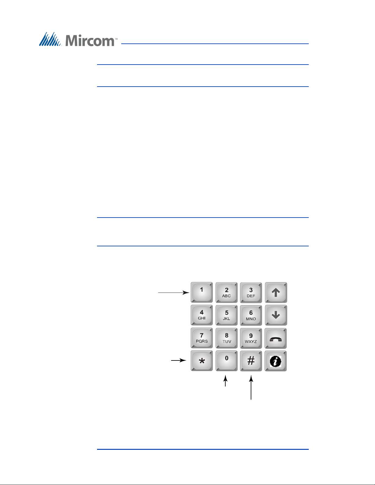
2.7.1 Adding a New Record
Enter Apt#
[ _ _ _ _ ]
2
ABC
3
DEF
1
5
JKL
6
MNO
4
GHI
8
TUV
9
WXYZ
7
PQRS
0
*
#
press * once = backspace press # once = space
For Resident Apartment Number Entry Only
Table 3 describes the information for adding new resident information. Use the
information in Table 3 to help you add new records.
To enter a resident
1. From the configuration menu, select the database menu. The database
selection appears.
2. Press the telephone key to enter the Add Record selection. The Enter Apt#
box appears.
3. To enter an apartment number, use the number keys to select the
appropriate characters. Maximum number of characters is 8. See Figure 2
for information about the characters that correspond to each number.
Configuration
Press any number key once, twice, three or more times to cycle through the
characters associated with that key. Capital letters appear after you cycle
through all of the lower case letters. When you reach the character you
want, stop pressing the key and the character will remain in the display.
Note that arrow keys are not used.
Version 2.4 Telephone Access System Programming Manual 33
LT-979 Copyright 2016
Figure 2. Keypad commands for entering an ap artment number .
Page 34
Configuration
press once = comma
press twice = dash
press 3 times = left bracket
press 4 times = right bracket
press 5 times = /
press 6 times = &
press 10 times = 1
press 0 once to delete a character
press 0 twice = 0
press * once = move cursor back
press # once = move cursor forward
For Resident Name Entry Only
press 9 times = *
Note: If you accidentally enter the wrong character while configuring an
apartment number, press * once to backspace.
For example, to enter the apartment number “23B”,
a. Press “2” once for the “2”, and then wait for the cursor to advance.
b. Press “3” once for the “3”, and then wait for the cursor to advance.
c. Press “2” six times for the letter “B”.
d. Press the telephone key to save and continue.
4. Once you have entered the apartment number and pressed the telephone
key to accept, the Enter Dial Code screen appears. The list of all screens
that you need to configure to add a resident is given in Table 1. Press the
telephone key to save the information for a screen and then advance to the
next screen.
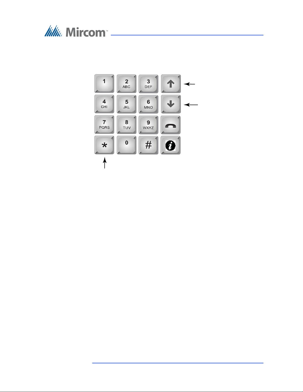
Note: The keypad functions differently for entering a resident’s name (see
Figure 3) and for entering a resident’s phone number (see Figure 4).
Refer to these figures when entering information for those screens.
34 Telephone Access System Programming Manual Version 2.4
LT-979 Copyright 2016
Figure 3. Keypad commands for en tering a resident name.
Page 35
Configuration
For Resident Telephone Number Entry Only
press to delete
press to add a comma
(generates a 1 second
delay when dialing)
press to add a semi-colon
(generates a 3 second
delay when dialing)
Figure 4. Keypad commands for entering a resident’ s telephon e
number.
5. When all the information for the new resident has been added, the display
shows “New Record Added” and then returns you to the configuration
menu.
Version 2.4 Telephone Access System Programming Manual 35
LT-979 Copyright 2016
Page 36

T able 1: List of Screens
Configuration
Database Menu NSL
System
Enter Apt#
YES YES Enter the resident’s apartment number (up to 8 digits).
ADC
System
Explanation/Description
[_ _ _ _]
Enter Dial Code
YES YES Enter the resident’s dial code (up to 4 digits).
_ _ _ _
Main Door sec. code
[_ _ _ _]
YES YES Enter a series of up to 4 digits from 0 to 9 to replace the
main door DTMF key (see section 2.6.3) for the specific
resident. To open the Main Door, the resident enters the
Main Door Security code followed by the # key. DO NOT
select “4”. This is used to refuse entry or disconnect. Do
not select the number that you are using for Call Wait
Key (2.6.14 Call Wait Key on page 24).
Aux Door sec. code
[_ _ _ _]
YES YES Enter a series of up to 4 digits from 0 to 9 to replace the
auxiliary door DTMF key (see section 2.6.4) for the
specific resident. To open the Auxiliary Door, the resident
enters the Auxiliary Door Security code followed by the #
key. DO NOT select “4”. This is used to refuse entry or
disconnect. Do not select the number that you are using
for Call Wait Key (2.6.14 Call Wait Key on page 24).
Enter Resident Name YES YES Enter the resident’s name. The name must be unique and a
maximum of 15 characters.
Line In Use
[x] Line 1 - 5
Enter Phone number
[____________]
YES YES Enter the speech path for resident to communicate to the
ADC line or to a relay control unit. Line 1 is default. Use
arrow keys to scroll and press # or * to make a selection.
N/A YES Enter the resident’s telephone number (up to 18 digits
including a comma that is used as 1 second delay). Use the
up arrow key for a comma (1 second pause) and the down
arrow key for a semi-color (3 second pause). Press Enter
(telephone key) to accept the telephone number.
Enter Relay Code
[_ _ _ _]
Enter Keyless Code
[_ _ _ _]
Keyless Code Corr
[x] Main door relay
[ ] Aux door relay
Enter Elev Rest Addr
[_ _]
Enter Elev Rest Code
YES N/A Enter the resident’s assigned relay code (NSL only).
Note: Relay codes start at 1 for the first relay, up to 1535.
YES YES Enter the assigned keyless code, up to 6 digits (if used). See
below for using keyless entry codes.
YES YES Select which door (main, auxiliary or both) can be opened
by the resident using a keyless code.
Use arrow keys to scroll and press # or * to make a
selection.
YES YES Enter the ID (or address) of the Elevator Restriction
controller for the resident.
YES YES Enter the elevator restriction relay number for the resident.
[_ _]
36 Telephone Access System Programming Manual Version 2.4
LT-979 Copyright 2016
Page 37

T able 1: List of Screens
Configuration
Hide Display
[x] Display
Ring Pattern
[x] Ring Pattern 1-5
YES YES This feature turns the resident information display ON or
OFF. When OFF the resident’s information is only
displayed in configuration mode. Use arrow keys to scroll
and press # or * to make a selection.
YES N/A Enter the ring pattern for the resident. See Table 2 for
available ring patterns. The default is 1. Use arrow keys to
scroll and press # or * to make a selection.
2.7.2 Using keyless entry codes
To enter the premises with a keyless entry code, you must first be in normal mode.
While in normal mode, press 0, after which point you are prompted with “Enter
keyless code”. The keyless code is a numeric value from 1 to 999999.
To enter your keyless code
1. Press 0. The keyless enter code appears.
2. Enter your keyless code.
2.7.3 Selecting a ring pattern (NSL System only)
The ring pattern selection is part of the Database Menu.
T able 2: Availa ble Ring Pattern
Ring
Available Ring Pattern
Pattern
1 2s ON 4s OFF standard
2 800ms
ON
3 200ms
ON
4 200ms
ON
400ms
OFF
400ms
OFF
400ms
OFF
800ms
ON
200ms
ON
800ms
ON
4s OFF distinct
400ms
OFF
400ms
OFF
800ms
ON
200ms
ON
4s OFF distinct
4s OFF distinct
5 One single ringing burst
ring A
ring B
ring C
ring D
Version 2.4 Telephone Access System Programming Manual 37
LT-979 Copyright 2016
Page 38

2.7.4 Editing Records
1212>Smith
1213 Jones
1214 Hath
1215 Johnson
1212>Smith
To edit a record
1. Select “Edit Record” and use the up/down key to scroll through the
residents.
2. Press the telephone button to select the resident’s name for editing.
3. Use the down arrow key to scroll down the list of fields, such as Apartment
number, Resident name, Dial code Keyless code, relay code, telephone
number, etc.
4. Once the arrow is pointing to the field that requires a change, press the
telephone key to edit.
Configuration
5. Re-enter the correct information.
When you are finished editing the record, the display returns to the record list. At
this point you may edit another record or press information key to return to the
configuration menu.
2.7.5 Deleting Records
Select this feature if you want to delete a resident’s name. This function deletes
one record at a time.
To delete a record
1. Scroll the arrow to “Delete Record” and press the telephone button. The
dial code and resident name appear:
2. Scroll the resident names with the up/down arrow keys to the record you
wish to delete.
38 Telephone Access System Programming Manual Version 2.4
LT-979 Copyright 2016
3. Press the telephone (enter) key to delete the entire record for the particular
resident. A warning message appears.
Page 39
4. When the warning appears “Delete Record? Y. Press the telephone key to
Sorting please wait
Sorting please wait
accept or the info key to cancel.
5. Once the record has been deleted, the screen will return to the Delete
Record function. At this point you may delete other records or press the
info key to return to the configuration menu.
2.7.6 Sorting by Name
Select this feature if you want the list of residents to be sorted alphabetically by
name.
To sort by name
1. Scroll the arrow to “Sort by Name” and press the enter (telephone) key.
Selecting this feature during database downloaded displays the following
message:
Configuration
The display now returns to the configuration menu.
2.7.7 Sorting by dial code
To sort by d-code
Select this feature if you want the list of residents to be sorted numerically by dial
code. Scroll the arrow to “Sort by d-code” and press enter (telephone) key. If you
have just downloaded the database, the following message appears:
The display now returns to the configuration menu.
2.7.8 Auto Programming
Auto programming allows you to add a group of residents from a minimum of 10
to a maximum of 200 names. This function allows you to auto program the
number of residents, resident name, start dial code, start keyless code and line
number to use.
This feature is particularly useful when adding a large number of residents into
the system.
Version 2.4 Telephone Access System Programming Manual 39
LT-979 Copyright 2016
Page 40
Table 3 describes the information you will need to auto program the panel.
Number of Records
< 010>
T able 3: Auto Programming Information
Configuration
Programming Menu
Number of Records
[____]
Enter Resident
Name
[____________]
Start Dialcode
[____]
Start Keyless Code
[____]
Line Number to use
[__]
Start Relay Number
[____]
NSL
System
YES YES
YES YES
YES YES
YES YES
YES YES
YES N/A
System
ADC
Explanation/Description
Enter the total number of residents to auto
program (4 digits). Scroll up or down to the
desired number, then press enter (telephone
key). Must be 10 or more.
Enter the resident’s name (maximum 10
characters).
Enter the start number of Dial Codes to auto
program. The starting code will be entered in
increments of 1, up to the number of residents
entered.
Enter the start number of the keyless codes, if
used. The starting code will be entered in
increments of 1, up to the number of residents
entered. These codes are used by the visitors to
enter without calling the resident.
Enter the Line number you wish for this lobby
unit to connect to. This Line numbers will be
used by the number of residents entered. Lines
1 to 5 are available.
Enter the start relay number to auto program.
The starting relay number will be entered in
increments of 1, up to the number of residents
entered. Please note that the relay number
starts at 1 for the first relay.
40 Telephone Access System Programming Manual Version 2.4
LT-979 Copyright 2016
To use the auto program
1. Scroll the arrow to “Auto Program” database menu and press the enter
(telephone) key. The display will now show the following message:
2. Use the up arrow to move from number of residents in increments of 5 to
the desired number. The maximum depends on the TX3 Model (it can be
200, 1000 or 2000).
Note: Only 200 names can be added at a time.
Page 41
Configuration
Enter Resident
Name
Start Dial Code
Start Keyless Code
Line Number to use
Delete all records?
3. Press the telephone (enter) key to accept. The next screen will ask for
resident name. Enter one of the resident names using the alphanumeric
keypad.
4. Press the telephone (enter) key to accept. The next screen will ask for the
resident’s dial code. All the rest of the dial codes increase by one.
5. Use the number keypad to enter the start dial code. The next screen asks
for the resident’s keyless code. All the rest of the keyless code increase by
one.
6. Use the number keypad to enter the start keyless code. The next screen
asks which audio line to use.
7. Use the up arrow to enter the line number. Press the enter (telephone) key
to accept.
8. Press info key to return to previous menu. View the residents entered by
scrolling page up and down using the * and # keys. To enter the proper
resident names, use the edit feature.
2.7.9 Deleting All Records
Select this feature if you want to delete all the resident data (all names, dial codes,
everything).
To delete all the resident data
1. Scroll the arrow to “Delete all Records” and press the enter (telephone)
key. The following message appears:
2. Press the enter (telephone) key to accept or the info key to cancel. The
display now returns to the configuration menu.
Version 2.4 Telephone Access System Programming Manual 41
LT-979 Copyright 2016
Page 42

2.8 Schedule Menu
Schedule Options
1 Add
2 Edit
3 Delete
Enter Label
Schedule Added
The schedule menu lets you set up a timetable to establish when certain panel
functions are permitted to occur, such as when calls to residents are allowed,
when residents can grant access to a visitor or when the postal lock can be used.
These schedules are designated and listed by name, and are available for selection
wherever it is necessary to invoke access permission.
Each schedule consists of eight periods.
To configure a schedule
1. Press the arrow to scroll to “Schedules” in the main configuration menu
and press the enter (telephone) key. The “Schedules” selection appears.
Configuration
2. You are able to add, edit or delete any schedule except “Always” and
“Never”.
To add a schedule
3. Select Add. The “Enter Label” selection appears.
4. Create a label, then add a start, end time and the days of the week the
schedule will be active.
5. Define each of the eight periods for the schedule. At the end of the schedule
configuration the “Schedule Added” message appears.
6. Press the telephone (enter) key to accept.
7. Press info key to return to previous menu.
42 Telephone Access System Programming Manual Version 2.4
LT-979 Copyright 2016
Page 43

To edit or delete a sc hedule
Holiday Options
1 Add
2 Edit
3 Delete
1. Select Edit or Delete. A list of all the schedules appears.
2. Press the arrow keys to scroll to the schedule you would like to edit or
delete.
3. Press the telephone (enter) key to accept.
4. Press info key to return to previous menu.
2.9 Holidays Menu
The Holidays menu lets you define the holidays for your schedules. When you
select Holiday for any of the periods in a schedules, all of the holidays defined in
this menu are added to the period for that schedule. By default, the TX3 system
comes with “New Year” already defined as a holiday.
To configure a holiday
Configuration
1. Scroll the arrow to “Holidays” in the main configuration menu and press
the enter (telephone) key. The “Holiday Options” selection appears.
To add a holiday
1. Select Add. The “Enter Label” menu appears
. You can add, edit or delete
any holiday. By default, “New Year” is already programmed into the
system.
2. Create a label, then a start and end time. Then select if this is holiday is an
annual occurrence.
3. Press the telephone (enter) key to accept. The message “Holiday Added” is
displayed on the screen and you are then returned to the “Holiday Options”
screen.
To edit a holiday
1. Select “Edit”. A list of all the holidays appears.
2. Press the arrow keys to scroll to the holiday you would like to edit.
Version 2.4 Telephone Access System Programming Manual 43
LT-979 Copyright 2016
Page 44

Configuration
---New Year -1 Label
2 Start Time/Date
3 End Time/Date
4 Repeat Annually
3. Press the telephone (enter) key to accept.
4. Press the arrow keys to scroll to the item you want to edit for the holiday
(that is, “Label”, “Start Time/Date”, “End Time/Date”, or “Repeat
Annually“), and then press the telephone (enter) key.
5. Make your edits to the item, and then press the telephone (enter) key to
accept it. You are returned to the Holiday edit screen.
6. If you want to edit more items for the holiday, repeat steps 4. and 5. above.
7. Press info key to save your edits.
8. Press the info key to return to the “Holiday Options” menu.
To delete a holiday
1. Select Delete. A list of all the holidays appears.
2. Press the arrow keys to scroll to the holiday you would like to delete, and
then press the telephone (enter) key to select the holiday for deletion.
3. Press the telephone (enter) key to accept the deletion.
4. Press the info key to return to the “Holiday Options” menu.
2.10 Factory Default
The “Factory Default” selection lets you apply the factory default settings for the
telephone access system.
Note: Selecting the Factory Default does not delete any resident
information.
44 Telephone Access System Programming Manual Version 2.4
LT-979 Copyright 2016
Page 45

To set the Factory Default
Reset to default? <Y>
Ipt/Opt Options
1 Inputs
2 Outputs
Input Types
1 Postal lock
2 Fire P Override
3 Door Sense
4 GP Input 3
5 GP Input 4
Ipt Active State
[ ] Close
1. Scroll the arrow to “Factory Dflt” in the main configuration menu and
press the enter (telephone) key. The Factory Default confirmation
selection appears.
2. Press the telephone (enter) key to accept or i to cancel.
2.11 Input/Output
The Inputs and Outputs selection lets you define specific devices connected to
each input and output.
To access Inputs and Outputs
1. Press the arrow key to scroll to “Input/Output” in the main configuration
menu. The “Input/Output” selection appears.
Configuration
Version 2.4 Telephone Access System Programming Manual 45
LT-979 Copyright 2016
To define inputs
1. Press the arrow key to scroll to Inputs, and press the enter (telephone) key.
The “Input Types” selection appears.
2. Press the arrow key to scroll to the input you wish to configure and press
the telephone (enter) key. The Input Active State selection appears.
Page 46

Configuration
Supervised for[ x ] No supervision
[ ] Open
[ ] Short
[ ] Open & Short
Output Types
1 Main Door lock
2 Aux Door lock
3 GP Output 3
4 GP Output 4
Opt Active State
< > De-energized
< x > Energized
3. Use the “#” key to define the input state as open or closed.
4. Press the telephone (enter) key to accept. The circuit supervision selection
appears.
5. Press the arrow key to scroll to the input you wish to configure and use the
“#” key to define the input state as No supervision, Open, Short or Open &
Short
6. Press the telephone (enter) key. The “Input Types” selection appears.
7. Proceed with the rest of the input configuration or
8. Press info key to return to previous menu.
To define outputs
1. Press the arrow key to scroll to Outputs, and press the enter (telephone)
key. The Output selection appears.
2. Press the arrow key to scroll to the output you wish to configure and press
the telephone (enter) key. The Output Active State selection appears.
46 Telephone Access System Programming Manual Version 2.4
LT-979 Copyright 2016
3. Press the arrow key to scroll to the input you wish to configure and use the
“#” key to define the output state as energized or de-energized.
4. Press the telephone (enter) key. The Output selection appears.
Page 47

5. Proceed with the rest of the input configuration or
Correlation
1 Add
2 Edit
3 Delete
Event Type
[ X ]Input Active
[ ] Call Started
[ ] Call Ended
[ ] Call Connected
[ ] Access Granted
[ ] Access Denied
[ ] System Normal
Event Data
1 GP Input 1
2 GP Input 2
6. Press info key to return to previous menu.
2.12 Correlations
The Correlation selection lets you associate specific input events with specific
output actions.
To configure a correlation
1. Press the arrow to scroll to “Correlations” in the main configuration menu
and press the enter (telephone) key. The “Correlation” selection appears.
Configuration
To make a correlation
2. Select Add. The “Event” selection appears.
3. Press the arrow key to scroll to a specific type of input and press the
telephone (enter) key. The Event Data selection appears.
Version 2.4 Telephone Access System Programming Manual 47
LT-979 Copyright 2016
Page 48
Configuration
Response Time
< >Turn Output ON
< x >Turn Output OFF
Response Data
< >GP Output 1
< x >GP Output 2
Select Schedule
0 Always
Corr Timer
[ 001]
Node Address
4. Press the arrow key to scroll to a specific type of input event and press the
telephone (enter) key. The “Response Type” selection appears.
5. Press the arrow key to scroll to a specific type of output action (response)
and press the telephone (enter) key. The “Response Data” selection
appears.
6. Press the arrow key to scroll to a specific output and press the telephone
(enter) key. The “Schedule” selection appears
7. Press the arrow key to select a specific schedule and press the telephone
(enter) key. The “Correlation Timer” entry appears
8. Press the arrow key to specify the duration for the correlation and press the
telephone (enter) key. The “Node address” entry appears. An output
action occurs on the panel designated by its node address, including the
originating the panel. Setting an address of 0 sets the output action for all
panels.
9. Press the arrow key to scroll to select a node address and press the
telephone (enter) key. The message Correlation Updated appears.
10. Press info key to return to previous menu.
48 Telephone Access System Programming Manual Version 2.4
LT-979 Copyright 2016
Page 49

To edit or delete a corre lation
Enter Access Level
< 001>
1. Press the arrow to scroll to “Correlations” in the main configuration menu
and press the enter (telephone) key. The “Correlation” menu appears.
2. Select Edit or Delete. A list of all the correlations appears.
3. Press the arrow keys to scroll to the correlation you would like to edit or
delete.
4. Press the telephone (enter) key to accept.
5. Press info key to return to previous menu.
2.13 Changing Passcodes
The Changing Passcodes selection lets you change your passcode for your access
level. There are three access levels.
Level 1. Not used.
Configuration
Level 2. Level 2 passcode allows access to the operation menu.
Level 3. Level 3 passcode allows access to both operation and configuration
menu. The level 3 passcode is also a network passcode used by the configurator
software. If the level 3 passcode changes, the configurator will not be able to
connect to the panel unless the network password is set to the level 3 passcode.
To change a passcode
1. Press the arrow to scroll to “Change Passcode” in the main configuration
menu and press the enter (telephone) key. The “Enter Access Level” entry
appears.
2. Press the arrow keys to scroll to your access level and press the telephone
(enter) key to accept.
3. Enter the new passcode. It can be up to 10 digits long.
Note: If you forgot the new passcode, call Mircom’s Technical Support
Department. See Technical Support contact information in
Section 1.5).
Version 2.4 Telephone Access System Programming Manual 49
LT-979 Copyright 2016
Page 50
4. Press the telephone (enter) key to accept. The “Enter New Passcode” entry
Enter new Passcode
----------
Re-enter new Passcode
----------
appears.
5. Press the enter (telephone) key to enter the new passcode. The “Re-enter
New Passcode” entry appears.
6. Re-enter the new passcode.
7. Press the enter (telephone) key to finalize entry of the new passcode.
8. Press info key to return to previous menu.
2.14 T est LCD
Configuration
The Test LCD selection lets you view all 255 character lines.
To test the LCD
1. Press the arrow to scroll to “Test LCD” in the main configuration menu
and press the enter (telephone) key. The “Test LCD” menu appears.
2. Press the arrow keys to scroll through the character lines.
3. Press info key to return to previous menu.
50 Telephone Access System Programming Manual Version 2.4
LT-979 Copyright 2016
Page 51

W arranty & Warning Information
Limited Warranty
Mircom Technologies Ltd. together with its subsidiaries and affiliates
(collectively, the “Mircom Group of Companies”) warrants the original
purchaser that for a period of two years from the date of manufacture, the product
shall be free of defects in materials and workmanship under normal use. During
the warranty period, Mircom shall, at its option, repair or replace any defective
product upon return of the product to its factory, at no charge for labour and
materials. Any replacement and/or repaired parts are warranted for the
remainder of the original warranty or ninety (90) days, whichever is longer. The
original owner must promptly notify Mircom in writing that there is defect in
material or workmanship, such written notice to be received in all events prior to
expiration of the warranty period.
International Warranty
The warranty for international customers is the same as for any customer within
Canada and the United States, with the exception that Mircom shall not be
responsible for any customs fees, taxes, or VAT that may be due.
Conditions to V oid W arranty
This warranty applies only to defects in parts and workmanship relating to
normal use. It does not cover:
• damage incurred in shipping or handling;
• damage caused by disaster such as fire, flood, wind, earthquake or
lightning;
• damage due to causes beyond the control of Mircom such as excessive
voltage, mechanical shock or water damage;
• damage caused by unauthorized attachment, alterations, modifications or
foreign objects;
• damage caused by peripherals (unless such peripherals were supplied by
Mircom);
• defects caused by failure to provide a suitable installation environment for
the products;
• damage caused by use of the products for purposes other than those for
which it was designed;
• damage from improper maintenance;
Version 2.4 Telephone Access System Programming Manual 51
LT-979 Copyright 2016
Page 52

• damage arising out of any other abuse, mishandling or improper
application of the products.
Warranty Procedure
To obtain service under this warranty, please return the item(s) in question to the
point of purchase. All authorized distributors and dealers have a warranty
program. Anyone returning goods to Mircom must first obtain an authorization
number. Mircom will not accept any shipment whatsoever for which prior
authorization has not been obtained.
Note: Unless specific pre-authorization in writing is obtained from
Note: Mircom’s liability for failure to repair the product under this
Mircom management, no credits will be issued for custom
fabricated products or parts or for complete fire alarm system.
Mircom will at its sole option, repair or replace parts under
warranty. Advance replacements for such items must be purchased.
warranty after a reasonable number of attempts will be limited to a
replacement of the product, as the exclusive remedy for breach of
warranty.
Disclaimer of Warranties
This warranty contains the entire warranty and shall be in lieu of any and all other
warranties, whether expressed or implied (including all implied warranties of
merchantability or fitness for a particular purpose) and of all other obligations or
liabilities on the part of Mircom neither assumes nor authorizes any other person
purporting to act on its behalf to modify or to change this warranty, nor to assume
for it any other warranty or liability concerning this product.
This disclaimer of warranties and limited warranty are governed by the laws of
the province of Ontario, Canada.
Out of Warranty Rep airs
Mircom will at its option repair or replace out-of-warranty products which are
returned to its factory according to the following conditions. Anyone returning
goods to Mircom must first obtain an authorization number. Mircom will not
accept any shipment whatsoever for which prior authorization has not been
obtained.
52 Telephone Access System Programming Manual Version 2.4
LT-979 Copyright 2016
Page 53

WARNING
NOTE
Products which Mircom determines to be repairable will be repaired and
returned. A set fee which Mircom has predetermined and which may be revised
from time to time, will be charged for each unit repaired.
Products which Mircom determines not to be repairable will be replaced by the
nearest equivalent product available at that time. The current market price of the
replacement product will be charged for each replacement unit.
Mircom recommends that the entire system be completely tested on a regular
basis. However, despite frequent testing, and due to, but not limited to, criminal
tampering or electrical disruption, it is possible for this product to fail to perform
as expected.
Under no circumstances shall Mircom be liable for any special, incidental, or
consequential damages based upon breach of warranty, breach of contract,
negligence, strict liability, or any other legal theory. Such damages include, but
are not limited to, loss of profits, loss of the product or any associated equipment,
cost of capital, cost of substitute or replacement equipment, facilities or services,
down time, purchaser’s time, the claims of third parties, including customers, and
injury to property.
MIRCOM MAKES NO WARRANTY OF MERCHANTABILITY OR
FITNESS FOR A PARTICULAR PURPOSE WITH RESPECT TO ITS
GOODS DELIVERED, NOR IS THERE ANY OTHER WARRANTY,
EXPRESSED OR IMPLIED, EXCEPT FOR THE WARRANTY
CONTAINED HEREIN.
Version 2.4 Telephone Access System Programming Manual 53
LT-979 Copyright 2016
Page 54

Special Notices
Product Model Number: TX3
AC REN (U.S.): 0.0B
AC REN (CANADA): 0.0
Complies With
Federal Communications Commission (FCC):
• TIA-968-A Technical requirement for connection of equipment tot he
telephone network.
• CFR 47, Part 15, Subpart B, Class B
• Unintentional Radiators
Industry Canada (IC):
• Terminal attachment programme
• CS-03, Issue 8 - Certification Specifications
• ICES-003, ISSUE 4, CLASS B
• Verification Authorization - Digital Apparatus
Registration Numbers
FCC (U.S.): 1M8TE00BTX3
IC (Canada): 1156A-TX3
Industry Canada Notice for all TX3 Products Sold in Canada
The Industry Canada label identifies certified equipment. This certification
means that the equipment meets certain telecommunications network protective,
operational, and safety requirements. Industry Canada does not guarantee the
equipment will operate to the user's satisfaction. Before installing this
equipment, users should ensure that it is permissible to be connected to the
facilities of the local telecommunication company. The equipment must also be
installed using an acceptable method of connection. The customer should be
aware that compliance with the above conditions may not prevent degradations
of service in some situations.
54 Telephone Access System Programming Manual Version 2.4
LT-979 Copyright 2016
Page 55

Repairs to certified equipment should be made by an authorized Canadian
maintenance facility designated by the supplier. Any repairs or alteration made
by the user to this equipment, or equipment malfunctions, may give the
telecommunications company cause to request the user to disconnect the
equipment. Users should ensure for their own protection that the earth ground
connections of the power utility, telephone lines and internal metallic water pipe
system, if present, are connected together. This is necessary both for proper
operation and for protection.
Caution: Users should not attempt to make such connections themselves, but
should contact the appropriate electric inspection authority, or
electrician, as appropriate.
Note: The Ringer Equivalence Number (REN) assigned to each terminal
device provides an indication of the maximum number of terminals
allowed to be connected to a telephone interface. The termination
on an interface may consist of any combination of devices subject
only to the requirement that the sum of the RENs of all the devices
does not exceed five.
FCC Notice for all TX3 Products Sold in the U.S.A.
Type of Service
The TX3 is designed to be used on standard device telephone lines. It connects to
the telephone line by means of a standard jack called the USOC RJ-11C (or
USOC FJ45S). Connection to telephone company-provided coin service (central
office implemented systems) is prohibited. Connection to party lines service is
subject to state tariffs.
Telephone Company Procedures
The goal of the telephone company is to provide you with the best service it can.
In order to do this, it may occasionally be necessary for them to make changes in
their equipment, operations or procedures. If these changes might affect your
service or the operation of your equipment, the telephone company will give you
notice, in writing, to allow you to make any changes necessary to maintain
uninterrupted service.
In certain circumstances, it may be necessary for the telephone company to
request information from you concerning the equipment which you have
connected to your telephone line. Upon request of the telephone company,
provide the FCC registration number and the ringer equivalence number (REN);
both of these items are listed on the equipment label. The sum of all of the RENs
Version 2.4 Telephone Access System Programming Manual 55
LT-979 Copyright 2016
Page 56

on your telephone lines should be less than five in order to assure proper service
from the telephone company. In some cases, a sum of five may not be useable on
a given line.
Changes to Telephone Service
The telephone company may make changes in its facilities, equipment,
operations or procedures that could affect the operation of the equipment. If this
happens the telephone company will provide advance notice in order for you to
make necessary modifications to maintain uninterrupted service.
Ringer Equivalence Number
The REN is used to determine the number of devices that may be connected to a
telephone line. Excessive RENs on a telephone line may result in the devices not
ringing in response to an incoming call. In most but not all areas, the sum of
RENs should not exceed five (5.0). To be certain of the number of devices that
may be connected to a line, as determined by the total RENs, contact the local
telephone company. For products approved after July 23, 2001, the REN for this
product is Customer Information 3 July 2003 part of the product identifier that
has the format US:AAAEQ##TXXXX. The digits represented by ## are the
REN without a decimal point (e.g., 03 is a REN of 0.3). For earlier products, the
REN is separately shown on the label.
If Problems Arise
If any of your telephone equipment is not operating properly, you should
immediately remove it from your telephone line, as it may cause harm to the
telephone network. If the telephone company notes a problem, they may
temporarily discontinue service. When practical, they will notify you in advance
of this disconnection. If advance notice is not feasible, you will be notified as
soon as possible. When you are notified, you will be given the opportunity to
correct the problem and informed of your right to file a complaint with the FCC.
Contact your telephone company if you have any questions about your telephone
line. In the event repairs are ever needed on the Communicator, they should be
performed by Mircom or an authorized representative of Mircom. For
information contact Mircom at the address and telephone numbers in
paragraph 1.5.
If this equipment, TX3 Telephone System, causes harm to the telephone network,
the telephone company will notify you in advance that temporary discontinuance
of service may be required. But if advance notice isn't practical, the telephone
company will notify the customer as soon as possible. Also, you will be advised
of your right to file a complaint with the FCC if you believe it is necessary.
56 Telephone Access System Programming Manual Version 2.4
LT-979 Copyright 2016
Page 57

Product Identifier
This equipment complies with Part 68 of the FCC rules and the requirements
adopted by the ACTA. On the back of the front panel cover of this equipment is
a label that contains, among other information, a product identifier in the format
US:AAAEQ##TXXXX. If requested, this number must be provided to the
telephone company.
Telephone Connection
A plug and jack used to connect this equipment to the premises wiring and
telephone network must comply with the applicable FCC Part 68 rules and
requirements adopted by the ACTA. You are responsible for installing a
compliant telephone cord and modular plug into this product as described in this
manual. It is designed to be connected to a compatible modular jack that is also
compliant. See installation instructions for details.
Equipment Failure
If trouble is experienced with the TX3 Telephone/Card Access System, for repair
or warranty information, please contact Mircom using the numbers in
paragraph 1.5. If the equipment is causing harm to the telephone network, the
telephone company may request that you disconnect the equipment until the
problem is resolved.
Use With Alarm Auto Dialers
If your institution has specially wired alarm equipment connected to the
telephone line, ensure the installation of the TX3 Telephone/Card Access System
does not disable your alarm equipment. If you have questions about what will
disable alarm equipment, consult your telephone company or a qualified
installer.
Version 2.4 Telephone Access System Programming Manual 57
LT-979 Copyright 2016
Page 58

Page 59

Page 60

 Loading...