

Mircom TX3-200-8U-B, TX3-120U-A, TX3-200-8U, TX3-200-8U-A, TX3-1000-8U Installation And Operation Manual
...
TX3 Series
TELEPHONE ACCESS SYSTEMS
Installation and Operation Manual
Version 3.7 Telephone Access System Installation and Operation Manual 1 (119)
LT-969 Copyright January 2017

Copyright January 2017 Mircom Inc.
All rights reserved.
TX3 Installation and Operation Manual rev 3.7
This manual, as well as the software described in it, is provided under licence or other agreements
and may be used or copied only in accordance with the terms of such license. The content of this
manual is furnished for informational use only. It is subject to change without notice, and should not
be construed as a commitment by Mircom. Mircom assumes no responsibility or liability for any errors
or inaccuracies that appear in this book.
Except as permitted by such license, no part of this publication may be reproduced, stored in a
retrieval system, transmitted in any form by means electronic, mechanical, using any recorded
media, or any other format without the prior written p ermission of Mircom.
Microsoft, MS-DOS, Windows, and Windows 2000/NT/XP are either registered trademarks or
trademarks of Microsoft Corporation in the United States and/or other countrie s.
Mircom
25 Interchange Way
Vaughan, Ontario
L4K 5W3
905.660.4655
Fax:905.660.4113
2 (119) Mircom Version 3.7
LT-969 Copyright January 2017

Contents
1 Introduction 8
1.1 TX3 Systems 9
1.2 Features 10
1.3 Lobby Control Unit Enclosures 11
1.4 Lobby Control Unit Accessories 17
1.5 Mounting requirements from the 2010 ADA Standards for Accessible
Design 17
1.6 Warranty and Special Notices 18
1.7 About This Manual 19
1.8 Contact Us 20
2 Enclosure Installation 22
2.1 Grounding the Telephone Access System 23
2.2 Installing the Enclosures and Lobby Control Unit 23
2.3 Installing the Heater 29
2.4 TX3-2000-8K-A Installation 30
3 TX3 System 36
3.1 TX3 System 37
3.2 Single Lobby Control Unit 38
3.3 Dual Lobby Control Units 40
3.4 Three Lobby Control Unit Configuration 41
3.5 Multiple Lobby Control Units 43
3.6 Networking TX3 Panels 44
3.7 Lobby Control Unit Wiring 47
4 Lobby Control Unit Setup 48
4.1 Controller Board 49
4.2 Controller Board Connectors - Bottom 51
4.3 Controller Board Connectors - Top 55
4.4 Modem Module 58
4.5 TX3-IP IP Module 59
4.6 RS-485 Add-on Module 59
4.7 Guard Phone Module 60
4.8 Guard Phone 61
4.9 Controller ID Setup 62
4.10 Configuration Using a PC 65
4.11 Updating Firmware 66
4.12 Beginning Configuration 66
5 NSL Relay Cabinet Installation and Wiring 68
5.1 NSL Relay Cabinet Mechanical Installation 69
5.2 NSL Relay Control Unit and Expanders 70
Version 3.7 Telephone Access System Installation and Operation Manual 3 (119)
LT-969 Copyright January 2017

5.3 Wiring the TX3-NSL-8M Main Controller Board 73
5.4 Updating Firmware 90
6 Elevator Restriction Unit Installation and Configuration 91
6.1 Elevator Restriction Cabinet Mechanical Installation 92
6.2 Elevator Restriction Units 94
6.3 Wiring the Elevator Restriction Unit 96
6.4 Elevator Restriction Controller Backplane 99
6.5 2012E Elevator Restriction Relay Card 100
6.6 Elevator Restriction Unit Configuration 101
6.7 Updating Firmware 103
7 Adding Controllers 104
7.1 Adding a Controller 105
8 Appendix 106
8.1 Specifications 107
9 Resident Operating Instructions 109
9.1 NSL Resident Operating Instructions 110
9.2 ADC Resident Operating Instructions 112
Warranty & Warning Information 113
Special Notices 116
4 (119) Telephone Access System Installation and Operation Manual Version 3.7
LT-969 Copyright January 2017

List of Figures
Figure 1 TX3-UFT Universal Series Flush Trim Ring 24
Figure 2 TX3-USFT Slim Line Universal Flush Trim Ring 27
Figure 3 Continental Enclosure Flush Mount 28
Figure 4 Heater TH-102 Installation Location 29
Figure 5 Dimensions of the 8 Line Kiosk (inc he s) 30
Figure 6 Reinforcement Bracket with bolts 31
Figure 7 Reinforcement Bracket with nuts 32
Figure 8 Kiosk Base Plate with bolts 32
Figure 9 Kiosk Mounting Holes 32
Figure 10 Base Plate Mounting Holes 33
Figure 11 Base Plate Dimensions (inches) 33
Figure 12 Fitting the Kiosk on the Base Plate 34
Figure 13 Fitting the Kiosk on the Base Plate (from below) 34
Figure 14 Attach the Kiosk to the base plate 35
Figure 15 Single Lobby Control Unit 38
Figure 16 Single Lobby Control Unit with ADC and NSL Lines 39
Figure 17 Single Entrance System Wiring 40
Figure 18 Dual Lobby Control Units 41
Figure 19 Multiple Lobby Control Units to Multiple Lines 42
Figure 20 Many Lobby Control Units to One Line 43
Figure 21 TX3 devices on an RS-485 network. 44
Figure 22 TX3 devices on an ethernet TCP/IP network. 45
Figure 23 Lobby control units using both ethernet and RS-485
networks 46
Figure 24 Lobby Control Unit Wiring 47
Figure 25 Lobby Control Unit Main Controller Board 49
Figure 26 Microphones and JW11 51
Figure 27 Controller Board Connectors - Bottom 51
Figure 28 Tamper Switch 53
Figure 29 RS-485 Connections 53
Figure 30 Power Supply 54
Figure 31 Controller Board Connectors - Top 55
Figure 32 Main Door Dry Contact Wiring 57
Figure 33 Modem Module Telephone Connectors 58
Figure 34 IP Module Data and Ethernet Connectors 59
Figure 35 RS-485 Add-on Module 60
Figure 36 Guard Phone Module 61
Figure 37 NSL Relay Cabinet 69
Figure 38 TX3-NSL-8M Relay Control Unit 71
Figure 39 NSL Expanders 72
Figure 40 TX3-NSL-8M Main Contr o lle r Boar d 73
Figure 41 NSL System with Telephone Line 75
Figure 42 NSL Controller Telephone Lines 76
Figure 43 NSL Backplane 78
Figure 44 ADSL-100 Filter Module Installation 79
Figure 45 Backplane Number Section 80
Figure 46 2012 NSL Relay Board 83
Figure 47 CA-71A BIX Block Wiring Configuration 84
Version 3.7 Telephone Access System Installation and Operation Manual 5 (119)
LT-969 Copyright January 2017

Figure 48 RJ-71C Punch-Down Block Wiring Configuration 87
Figure 49 Elevator Relay Cabinet 92
Figure 50 Lobby Control Unit with Elevator Restriction 94
Figure 51 Elevator Restriction Unit 95
Figure 52 Elevator Controller Board 96
Figure 53 Elevator Restriction Controller Board Wiring 98
Figure 54 Elevator Restriction Controller Backplane 99
Figure 55 2012E Elevator Restriction Relay Board 100
6 (119) Telephone Access System Installation and Operation Manual Version 3.7
LT-969 Copyright January 2017

List of Tables
Table 1 RS-485 Add-on Jumper Settings 60
Table 2 Lobby Control Unit SW1 DIP Switch Settings 63
Table 3 NSL Relay Cabinet Dimensions 70
Table 4 Sample Backplane Relay Addresses 81
Table 5 CA-71A BIX Block Identification Form 85
Table 6 RJ-71C Punch-Down Block Identification Form 88
Table 7 Lobby Control Unit SW2 DIP Switch Settings 101
Version 3.7 Telephone Access System Installation and Operation Manual 7 (119)
LT-969 Copyright January 2017

1 Introduction
This manual provides information about the installation and operation of the
Telephone Access System, and must be read in its entirety before beginning any
installation work.
Installation must be performed by a qualified technician and must adhere to the
standards and special notices set by the local regulatory bodies.
Note: Mircom periodically updates panel firmware and Configurator
Software to add features and correct any minor inconsistencies.
For information about the latest firmware or software visit the
Mircom website at www.mircom.com.
For warranty and special notices information see the Warranty and Special
Notices chapter on page 113.
Warning: The Telephone Access System assembly must be grounded by a
qualified electrician. An improperly grounded unit can result in
equipment malfunction and electrical shock.
This manual explains
• Lobby Control Unit Installation and Operation
• NSL Control Unit Installation and Operation
• Elevator Restriction Unit Installation and Operation
• Card Reader Unit Integration
8 (119) Telephone Access System Installation and Operation Manual Version 3.7
LT-969 Copyright January 2017

1.1 TX3 Systems
The Mircom's TX3 series of telephone access systems provide high quality twoway communication between residents and their visitors in a multi-unit dwelling
establishment.
The basic TX3 system consists of the TX3 Lobby Control Unit and depending on
the application, may be integrated with a combination of Mircom Elevator
Restriction Units, Card Access Units and Touch Screens. All access systems may
be networked together using either a peer-to-peer RS-485 connection, an ethernet
TCP/IP connections, or an ethernet TCP/IP network with RS-485 subnetworks.
The TX3 system is capable of providing ADC or NSL type telephone access
control from a single panel or from a networked system.
A maximum of 63 units are supported with any combination of Touch Screens,
Lobby Control Units, Elevator Restriction Units and Card Access Units. Valid
network addresses range from 1 to 63. One of the networked units with a real time
clock, such as Touch Screen, Lobby Control or Card Access must have their
network address set to 1. In addition, units can be connected to either an ethernet
TCP/IP network or a combination ethernet TCP/IP network with RS-485
subnetworks, both of which allow more than 64 units to be networked. See
Networking TX3 Panels on page 44 for more information.
Introduction
The access system can be configured as an autodialer controller (ADC) or as a no
subscriber line (NSL) system. Both system setups can be configured for multiple
entrances with independent doors and control devices such as electric door locks,
cameras, and garage doors.
1.1.1 ADC and NSL Capability
TX3 supports full ADC and NSL telephone connectivity from a single Telephone
Access System panel or from a networked system. A single panel supports up to
five ADC and/or NSL telephone lines.
An ADC connection requires a dedicated subscriber telephone line service
connected to an outside telephone line. This connection lets the visitor call the
tenant and access their voice mail.
An NSL type connection uses the existing building telephone lines for
communication and does not require a separate telephone line. This system may
consist of one or more Lobby Control Units connected to TX3-NSL-8M NSL
Units, typically located in the electrical/telephone room of a building. The NSL
units intercept all telephone lines into the building’s suites and communicate
directly to the resident phone using the Lobby Control Unit.
Note: Non-configurable PBX systems are not supported. For more
information, contact technical support at Mircom.
Version 3.7 Telephone Access System Installation and Operation Manual 9 (119)
LT-969 Copyright January 2017

1.1.2 Elevator Restriction Units
The TX3-ER-8 or TX3-ER-8-A Elevator Restriction Units limit building
accessibility by granting visitor access only to the destination floor.
1.1.3 Other Controllers
Other Mircom controllers, such as the Elevator Restrictor Unit and the Card
Access controller, may be networked with the Lobby Control Unit. The network
options include a peer-to-peer RS-485 network, an ethernet TCP/IP network, or a
combination ethernet TCP/IP network with RS-485 subnetworks. See
Networking TX3 Panels on page 44 for more information.
Notes: In order for a panel to connect to an ethernet TCP/IP network, it
must satisfy the following conditions.
• It must be IP capable. Panels that are IP capable are usually
denoted by a “-A” or “-B” at the end of their model names.
• If the panel is not a T ouch Screen, it must have a TX3-IP IP
Module installed.
Introduction
1.2 Features
Features of the TX3 series include:
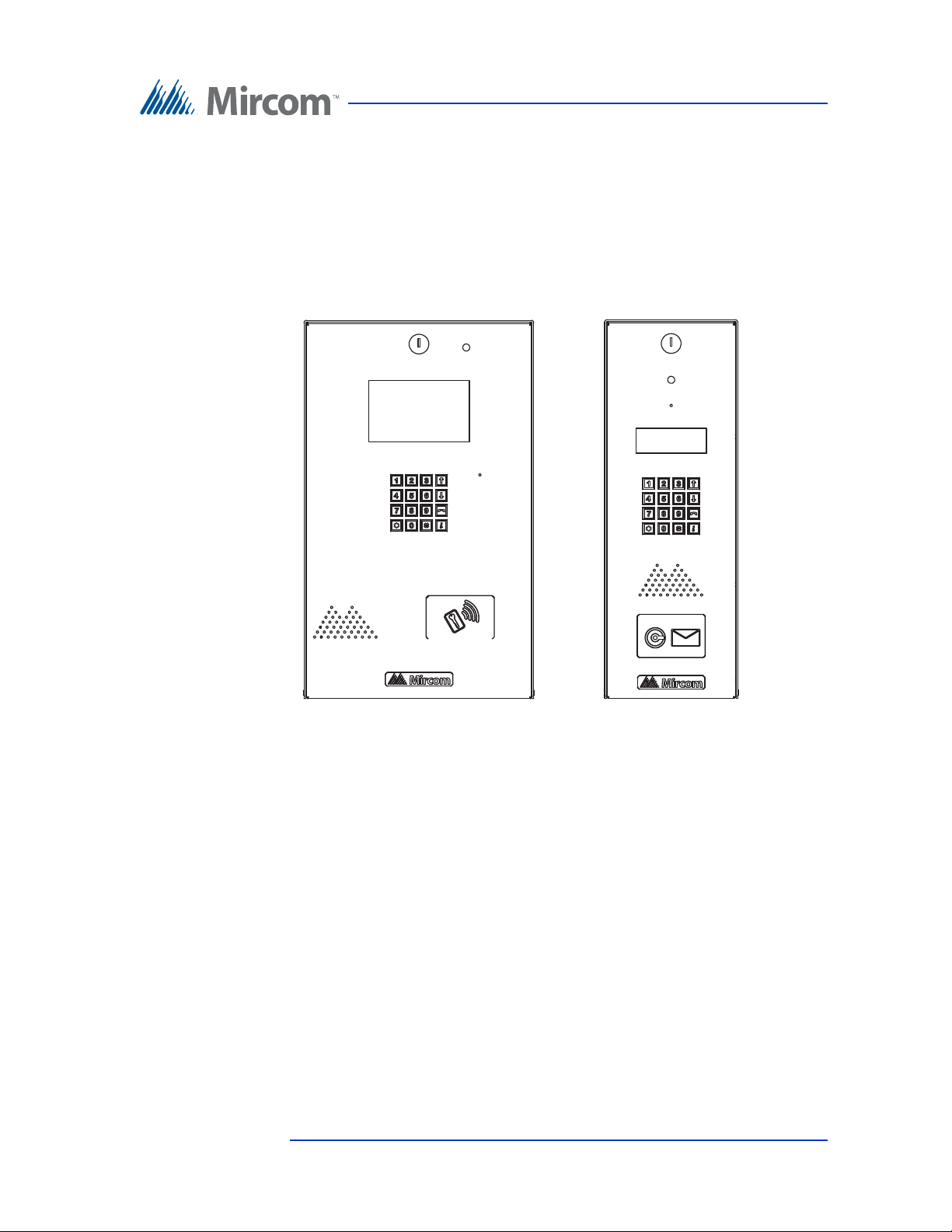
• Stainless steel front panel
• Universal Series enclosure with a built-in rain hood
• Large scrolling 8 x 20 LCD display that eliminates the need for an external
directory
• Back-lit 16 digit keypad with dedicated operational buttons for Page Up,
Page Down, Call and Info
• Provisions for postal lock and camera
• Multilingual Display and Voice Greeting (English, French-Canadian and
Spanish) that provides instructions on how to use the Lobby Control Unit
• Concierge/Security Desk/Guard Phone capability
• Card Access Interface
• Supports both Auto Dialer (ADC) and NSL (no phone bill)
• Ability to network panels together (peer-to-peer)
• Hands free, full duplex communication
• Flexible one to four digit resident dial codes
• Dials up to 18 digit telephone numbers
10 (119) Telephone Access System Installation and Operation Manual Version 3.7
LT-969 Copyright January 2017

• System can be configured locally using the keypad or a computer with the
TX3 configuration software
• Upload/download configuration files without taking the whole system off-
line
• Programming from one location
• Records a maximum of 5000 event logs
• Elevator restriction capability
• Schedule based call restrictions provide more security and flexibility
• Auto Unlock to leave the main door based on the selected schedule
• Capability of one person testing the NSL controller without using the
Lobby Control Unit
• Industry Canada and F.C.C. approved
1.3 Lobby Control Unit Enclosures
Introduction
There are four series of enclosures for Lobby Control Units:
Universal Series. The Universal Series enclosure is an indoor/outdoor unit for
the scrolling Lobby Control Unit.
Universal Slim-Line Series. The Universal Slim-Line enclosure is an indoor/
outdoor unit that is narrower and longer than the Universal and Continental
series, and is for the scrolling Lobby Control Unit. This series is also available as
a kit.
Continental Series. The Continental Series is a stainless steel indoor unit larger
than the Universal Series and is for the scrolling Lobby Control Unit.
Kiosk Free Standing.
1.3.1 Universal Series
The Universal Series enclosures are surface or semi-flush mounted with the
Lobby Control Units. Optional flush trim rings are available for semi-flush and
flush installations. A rain hood is included allowing for outdoor use.
The following Universal Panel models use the Scrolling Directory:
TX3-120U and TX3-120U-A: Electronic Scrolling Directory plus Paper
Directory Lobby Control Unit Kit
• Four-line by 20 character LCD display
• 120 name paper directory
Version 3.7 Telephone Access System Installation and Operation Manual 11 (119)
LT-969 Copyright January 2017

Introduction
• Main controller board for 200 residents
• PS-4P Transformer
• Universal Enclosure complete with Rain Hood and Light Assembly
• TX3-120U-A is IP capable
TX3-200-8U, TX3-200-8U-A and TX3-200-8U-B: Electronic Scrolling
Directory Lobby Control Unit Kit
• Eight-line by 20 character LCD display
• Main controller board for 200 residents
• PS-4P Transformer
• Universal Enclosure complete with Rain Hood and Light Assembly
• Designed for outdoor applications
• TX3-200-8U-A and TX3-200-8U-B are IP capable
• Provision for card reader (sold separately) or postal lock (TX3-200-8U-B
only)
• Provision for TX3-CX-1NP Single Door Control Module, sold separately
(TX3-200-8U-B only)
TX3-1000-8U, TX3-1000-8U-A and TX3-1000-8U-B: Electronic Scrolling
Directory Lobby Control Unit Kit
• Eight-line by 20 character LCD display
• Main controller board for 1000 residents
• PS-4P Transformer
• Universal Enclosure complete with Rain Hood and Light Assembly
• Designed for outdoor applications
• TX3-1000-8U-A and TX3-1000-8U-B are IP capable
• Provision for card reader (sold separately) or postal lock (TX3-1000-8U-B
only)
• Provision for TX3-CX-1NP Single Door Control Module, sold separately
(TX3-1000-8U-B only)
12 (119) Telephone Access System Installation and Operation Manual Version 3.7
LT-969 Copyright January 2017

TX3-2000-8U, TX3-2000-8U-A and TX3-2000-8U-B: Electronic Scrolling
Directory Lobby Control Unit Kit
• Eight-line by 20 character LCD display
• Main controller board for 2000 residents
• PS-4P Transformer
• Universal Enclosure complete with Rain Hood and Light Assembly
• Designed for outdoor applications
• TX3-2000-8U-A and TX3-2000-8U-B are IP capable
• Provision for card reader (sold separately) or postal lock (TX3-2000-8U-B
only)
• Provision for TX3-CX-1NP Single Door Control Module, sold separately
(TX3-2000-8U-B only)
1.3.2 Universal Slim-Line Series
The Universal Slim-Line series enclosure houses the following models and can
be surface or semi-flush mounted:
Introduction
TX3-200-4U-A and TX3-200-4U-B: Slim-Line Electronic Scrolling
Directory Lobby Control Unit Kit
• 4 Line by 20 LCD character display
• Main controller board for 200 residents
• PS-4P Transformer
• Slim-line Universal Enclosure complete with Rain Hood and Light
Assembly
• IP capable
• Provision for card reader (sold separately) or postal lock (TX3-200-4U-B
only)
• Provision for TX3-CX-1NP Single Door Control Module, sold separately
(TX3-200-4U-B only)
TX3-1000-4U-A and TX3-1000-4U-B: Slim-Line Electronic Scrolling
Directory Lobby Control Unit Kit
• 4 Line by 20 LCD character display
• Main controller board for 1000 residents
• PS-4P Transformer
• Slim-line Universal Enclosure complete with Rain Hood and Light
Assembly
• IP capable
Version 3.7 Telephone Access System Installation and Operation Manual 13 (119)
LT-969 Copyright January 2017

Introduction
• Provision for card reader (sold separately) or postal lock (TX3-1000-4U-B
only)
• Provision for TX3-CX-1NP Single Door Control Module, sold separately
(TX3-1000-4U-B only)
TX3-2000-4U-A and TX3-2000-4U-B: Slim-Line Electronic Scrolling
Directory Lobby Control Unit Kit
• 4 Line by 20 LCD character display
• Main controller board for 2000 residents
• PS-4P Transformer
• Slim-line Universal Enclosure complete with Rain Hood and Light
Assembly
• IP capable
• Provision for card reader (sold separately) or postal lock (TX3-2000-4U-B
only)
• Provision for TX3-CX-1NP Single Door Control Module, sold separately
(TX3-2000-4U-B only)
1.3.3 Universal Slim-Line Kit
The Universal Slim-Line series is available as a kit:
TX3-NSL-12K. The TX3-NSL-12K kit consists of:
• TX3-200-4U slim-line entry panel with speaker and microswitch
for postal lock
• 4x20 LCD display
• PS-4P transformer plug
• TX3-NSL-8M Master NSL Relay Cabinet with one PS-4P
transformer plug
• 2012K Twelve Telephone Relay Kit with a 2012 Twelve Telephone
Relay board and a 9106 Cable
• RJ-71C Punch Down Block for outdoor applications
TX3-NSL-12K-A. This is the IP capable version of the TX3-NSL-12K and
comes with the TX3-200-4U-A panel instead of the TX3-200-4U.
The Universal Panel Accessories consist of the following:
Model TX3-UFT. Universal Flush mounting trim for use with TX3-120U, TX3-
200-8U, TX3-1000-8U and TX3-2000-8U. Stainless steel.
Model TX3-USFT. Universal Slim-Line Flush mounting trim for TX3-200-4U.
Stainless steel.
14 (119) Telephone Access System Installation and Operation Manual Version 3.7
LT-969 Copyright January 2017

1.3.4 Continental Series
The Continental Series enclosure for Lobby Control Units are flush mounted and
for indoor use only. The following Continental Series models use the Scrolling
Directory:
TX3-120C-A: Electronic Scrolling Directory plus Paper Directory Lobby
Control Unit Kit
• Lighted sign box for directory or bulletins
• 4 Line backlit LCD electronic directory
• Flush mount for indoor applications
• Provisions for postal lock and camera
TX3-200-8C-A and TX3-200-8C-B: Electronic Scrolling Directory Lobby
Control Unit Kit
• Eight-line by 20 character LCD display
• Main controller board for 200 residents
Introduction
• PS-4P Transformer
• Continental Enclosure
• Designed for indoor applications
• IP capable
• Provision for card reader (sold separately) or postal lock (TX3-200-8C-B
only)
• Provision for TX3-CX-1NP Single Door Control Module, sold separately
(TX3-200-8C-B only)
TX3-1000-8C-A and TX3-1000-8C-B: Electronic Scrolling Directory Lobby
Control Unit Kit
• Eight-line by 20 character LCD display
• Main controller board for 1000 residents
• PS-4P Transformer
• Continental Enclosure
• Designed for indoor applications
• IP capable
• Provision for card reader (sold separately) or postal lock (TX3-1000-8C-B
only)
• Provision for TX3-CX-1NP Single Door Control Module, sold separately
(TX3-1000-8C-B only)
Version 3.7 Telephone Access System Installation and Operation Manual 15 (119)
LT-969 Copyright January 2017

Introduction
TX3-2000-8C-A and TX3-2000-8C-B: Electronic Scrolling Directory Lobby
Control Unit Kit
• Eight-line by 20 character LCD display
• Main controller board for 2000 residents
• PS-4P Transformer
• Continental Enclosure
• Designed for indoor applications
• IP capable
• Provision for card reader (sold separately) or postal lock (TX3-2000-8C-B
only)
• Provision for TX3-CX-1NP Single Door Control Module, sold separately
(TX3-2000-8C-B only)
TX3-200-8CH-A: Electronic Scrolling Directory Lobby Control Unit Kit
with Handset
• Eight-line by 20 character LCD display
• Handset
• Main controller board for 200 residents
• PS-4P Transformer
• Continental Enclosure
• Designed for indoor applications
• IP capable
TX3-1000-8CH-A: Electronic Scrolling Directory Lobby Control Unit Kit
with Handset
• Eight-line by 20 character LCD display
• Handset
• Main controller board for 1000 residents
• PS-4P Transformer
• Continental Enclosure
• Designed for indoor applications
• IP capable
TX3-2000-8CH-A: Electronic Scrolling Directory Lobby Control Unit Kit
with Handset
• Eight-line by 20 character LCD display
• Handset
16 (119) Telephone Access System Installation and Operation Manual Version 3.7
LT-969 Copyright January 2017

• Main controller board for 2000 residents
• PS-4P Transformer
• Continental Enclosure
• Designed for indoor applications
• IP capable
1.3.5 Kiosk Free Standing
TX3-2000-8K-A: 8 line Voice Entry panel, Kiosk style mount for 2000 names.
1.4 Lobby Control Unit Accessories
The Lobby Control Unit accessories consist of the following items:
• TX3-UFT Universal series flush trim ring.
• TX3-USFT Slim line Universal Series flush trim ring.
Introduction
• TX3-UGA Gooseneck mounting adapter designed for use with the
standard Universal Series enclosure for pedestals.
• TX3-USGA Gooseneck mounting adapter designed for use with the TX3-
200-4U Slim Line Universal enclosure pedestals.
• TH-102 Thermostat Heater with one PS-24P Transformer Plug
•CAM-2 TX3 Camera
• TX3-MDM Modem Module
• TX3-GPM Guard Phone Module
• TX3-USB-AD USB to RS-485 Adapter
• TX3-IP IP Module
• TX3-CX-1NP Single Door Control Module, PoE, 12 VDC, 24-48 VDC
1.5 Mounting requirements from the 2010 ADA St andards for Accessible Design
See http://www.ada.gov/ for more information.
308.2 Forward Reach.
308.2.1 Unobstructed. Where a forward reach is unobstructed, the high forward
reach shall be 48 inches (1220 mm) maximum and the low forward reach shall be
15 inches (380 mm) minimum above the finish floor or ground.
Version 3.7 Telephone Access System Installation and Operation Manual 17 (119)
LT-969 Copyright January 2017

Introduction
308.2.2 Obstructed High Reach. Where a high forward reach is over an
obstruction, the clear floor space shall extend beneath the element for a distance
not less than the required reach depth over the obstruction. The high forward
reach shall be 48 inches (1220 mm) maximum where the reach depth is 20 inches
(510 mm) maximum. Where the reach depth exceeds 20 inches (510 mm), the
high forward reach shall be 44 inches (1120 mm) maximum and the reach depth
shall be 25 inches (635 mm) maximum.
308.3 Side Reach.
308.3.1 Unobstructed. Where a clear floor or ground space allows a parallel
approach to an element and the side reach is unobstructed, the high side reach
shall be 48 inches (1220 mm) maximum and the low side reach shall be 15 inches
(380 mm) minimum above the finish floor or ground.
EXCEPTIONS:
1. An obstruction shall be permitted between the clear floor or ground space and
the element where the depth of the obstruction is 10 inches (255 mm) maximum.
2. Operable parts of fuel dispensers shall be permitted to be 54 inches (1370 mm)
maximum measured from the surface of the vehicular way where fuel dispensers
are installed on existing curbs.
308.3.2 Obstructed High Reach. Where a clear floor or ground space allows a
parallel approach to an element and the high side reach is over an obstruction, the
height of the obstruction shall be 34 inches (865 mm) maximum and the depth of
the obstruction shall be 24 inches (610 mm) maximum. The high side reach shall
be 48 inches (1220 mm) maximum for a reach depth of 10 inches (255 mm)
maximum. Where the reach depth exceeds 10 inches (255 mm), the high side
reach shall be 46 inches (1170 mm) maximum for a reach depth of 24 inches (610
mm) maximum.
EXCEPTIONS:
1. The top of washing machines and clothes dryers shall be permitted to be 36
inches (915 mm) maximum above the finish floor.
2. Operable parts of fuel dispensers shall be permitted to be 54 inches (1370 mm)
maximum measured from the surface of the vehicular way where fuel dispensers
are installed on existing curbs.
1.6 Warranty and S pecial Notices
Mircom values your business and always attempts to provide you with the very
best service.
Please see the Warranty and Special Notices chapter on page 113 for information
about the warranty and special notices about equipment use.
18 (119) Telephone Access System Installation and Operation Manual Version 3.7
LT-969 Copyright January 2017

1.7 About This Manual
This manual provides comprehensive information on the installation and
configuration of the TX3 Series Telephone Access System by the installation
technician. Tasks are described in the order that they are likely to be performed.
1.7.1 Version Control
The version number appears on the front cover and changes whenever there is a
major or minor update to any part of the system regarding operation or
configuration.
The following convention indicates major or minor changes:
Initial release. Version 1.00.0
Major change. Version 2.00.0
Minor change. Version 2.01.0
Introduction
Pre-release changes. Version 2.01.1
1.7.2 Additional Documentation
For additional documentation, see the following Mircom literature:
• TX3-CX Touch Screen Administrators Guide LT-995
• TX3-CX Card Access System Installation and Operation Manual LT-980
• LT-1160 TX3-CX-A8 Aperio Interface Panel Installation and Operation
Manual.
• TX3 Telephone Access System User’s Guide LT-968
• TX3 Two Door Card Access System Kit Catalogue Number 6531
• TX3 Series Elevator Restriction Accessories Catalogue Number 6532
Version 3.7 Telephone Access System Installation and Operation Manual 19 (119)
LT-969 Copyright January 2017
1.8 Contact Us
Mircom fosters a collaborative support process and environment in providing
early feedback to meet your specific needs.
You can contact us from Monday to Friday 8:00 A.M. to 5:00 P.M. E.S.T.
1.8.1 General Inquiries
Introduction
For general inquiries call us at the following numbers:
Toll Free: 1-888-660-4655
Local: 905-660-4655
1.8.2 Customer Service
Customer service is available at the following numbers:
Toll Free: 1-888-MIRCOM5
Local: 905-695-3535
Local Fax: 905-660-4113
Toll-Free Fax: 1-888-660-4113
1.8.3 Website
Visit the Mircom website, at www.mircom.com, to find the product information
you are looking for and to learn about troubleshooting, training and technical
support options.
The website provides avenues for customers to ask questions about new and
existing technologies, and receive expert technical support about software and
products. Visit www.mircom.com/chat.
20 (119) Telephone Access System Installation and Operation Manual Version 3.7
LT-969 Copyright January 2017

1.8.4 Email
As a customer you quickly become informed on how we can help with new
products and technologies. Contact Mircom at mail@mircom.com.
1.8.5 Technical Support
For technical support contact Mircom’s Technical Support Department between
8 A.M. and 5 P.M. (EST) Monday through Friday, excluding holidays.
Toll Free: 1-888-MIRCOM5
Local: 905-695-3535
Local Phone: 905-660-4655
Toll Free Phone: 1-888-660-4655
Email: techsupport@mircom.com
Introduction
Version 3.7 Telephone Access System Installation and Operation Manual 21 (119)
LT-969 Copyright January 2017

2 Enclosure Installation
This chapter provides information on how to install the various enclosures and
panels.
This chapter explains
• Enclosure installation
• Lobby Control Unit installation
• Heater installation
• TX3-2000-8K-A Installation
22 (119) Telephone Access System Installation and Operation Manual Version 3.7
LT-969 Copyright January 2017

Enclosure Installation
2.1 Grounding the T elephone Access System
Grounding reduces the risk of electrical shock by providing an alternate escape
route for the electrical current. Telephone Access System is equipped with a
16 gauge electrical wire attached to the panel chassis ground post.
To ground the Telephone Access System attach one end of the supplied cable to
a suitable grounding wire and connect it to the site ground.
2.2 Installing the Enclosures and Lobby Control Unit
Lobby Control Units use one of the following three types of Lobby Control Unit
enclosures:
Universal Series. The Universal Series are surface or semi-flush mounted with
the lobby Lobby Control Units. Optional flush trim rings are available for semiflush and flush installations. The semi-flush trim is the TX3-UFT. A rain hood is
included allowing for outdoor use.
Universal Slim-Line Series. The Universal Slim-Line series enclosure houses
the TX3-200-4U model and can be surface or semi-flush mounted. The semiflush trim is the TX3-USFT.
Continental Series. The Continental Series enclosure for Lobby Control Units
are flush mounted.
Version 3.7 Telephone Access System Installation and Operation Manual 23 (119)
LT-969 Copyright January 2017
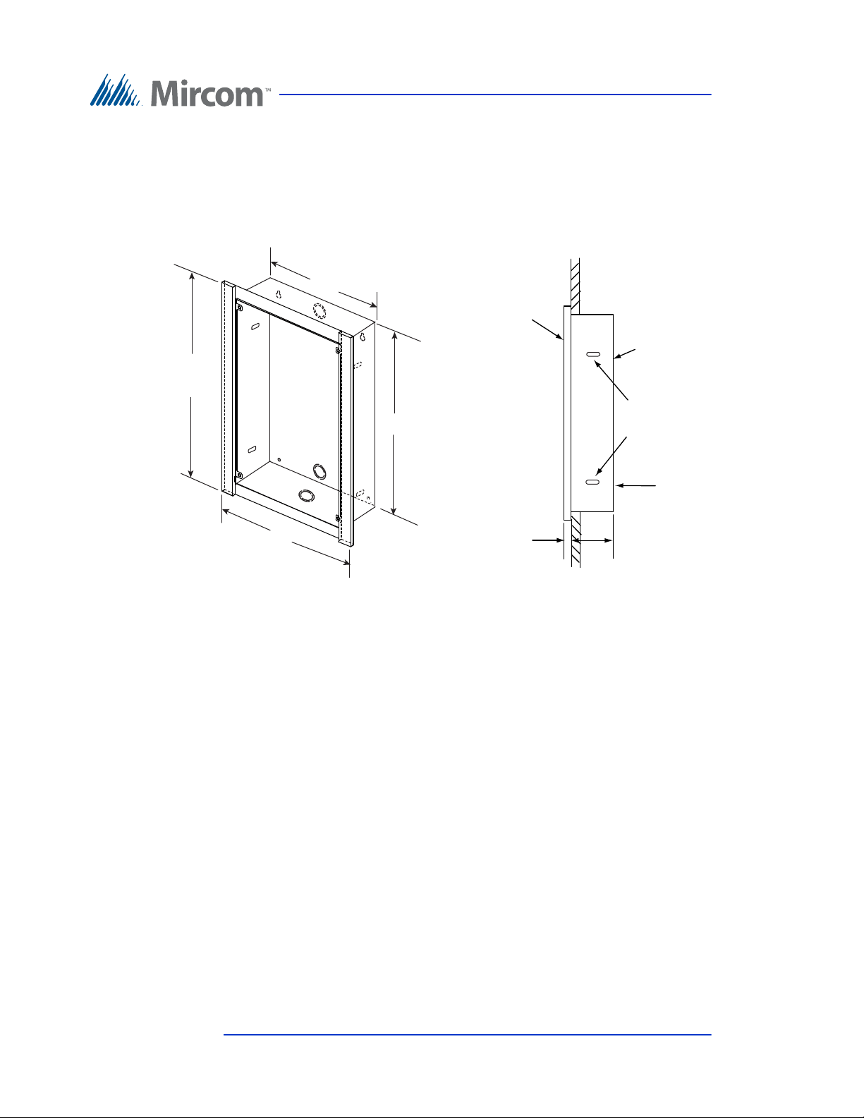
2.2.1 Installing the Universal enclosure
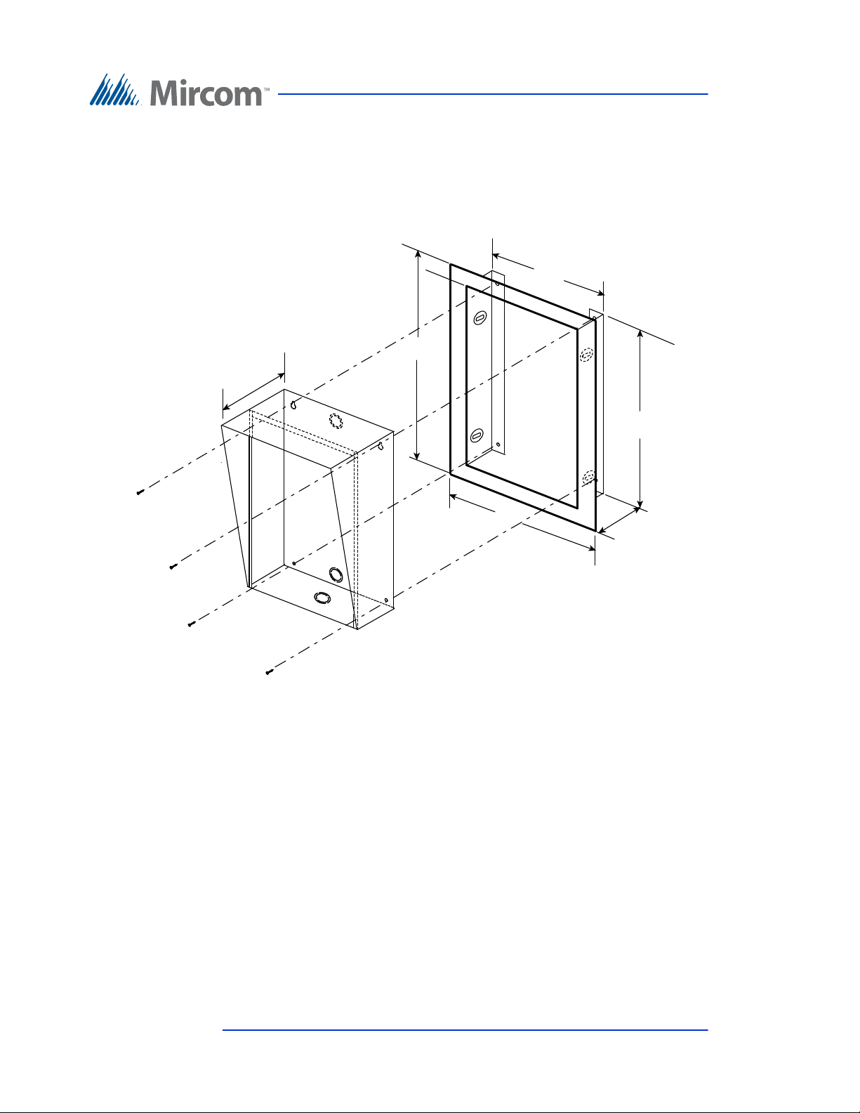
10 5/8"
13 1/8 "
16 1/4”
19 5/8"
2 3/4"
4 1/2 "
Dimension of the Enclosure without
the flush trim.
Cut out in wall should be :
16.25” H x 10.6”W x 2.75” D at the bottom
3” at the top
Universal
Enclosure
Semi-Flush Trim
TX3-UFT
The Universal enclosure mounts inside the wall with or without the TX3-UFT
Universal Series Flush Trim Ring TX3-UFT. This Trim Ring houses the
universal series enclosure as shown in Figure 1.
Enclosure Installation
Figure 1. TX3-UFT Universal Series Flush Trim Ring
To install the Universal e nclosure with the Flush Trim Ring to the
wall stud
1. Find a suitable location for the enclosure next to a wall stud.
2. Using the enclosure as a template, trace an opening in the wall for the cut
out with one side aligned with the side of the wall stud.
3. Cut an opening in the wall ensuring that one side is aligned with the wall
stud.
24 (119) Telephone Access System Installation and Operation Manual Version 3.7
LT-969 Copyright January 2017

Enclosure Installation
4. Using the semi-flush trim ring as a template, insert the trim ring into the
wall cut out and mark the top mounting hole location as shown in Figure 1.
Ensure that at least one side is beside a wall stud.
5. Place the screw halfway into the wall into the marked hole location using
the supplied screw.
6. Hang the Trim Ring onto the top screw.
7. Screw the lower two screw at the bottom of the trim ring halfway into the
wall.
8. Tighten the two screws into place.
9. Insert the universal enclosure with the rain hood inside the trim ring.
10. Secure the universal enclosure into the trim ring using the supplied four
screws as shown in Figure 1.
To surface mount the Univ ersal enclosure
1. Find a suitable location for the Universal enclosure over a wall stud.
2. Using the Universal enclosure as a template, mark the two side mounting
hole locations as indicated in Figure 1. Ensure that at least one side is over
a wall stud.
3. Remove the enclosure and place the screws halfway into the marked hole
location and wall stud using the supplied screws.
4. Place the Universal enclosure onto the two screws.
5. Screw the two side screws of the Universal enclosure halfway into the
wall.
6. Tighten all four screws into place.
Note: The enclosure can also be mounted directly onto the drywall using
anchors.
To install the Universal enclosur e with the Flush Trim Ring to the
back wall
1. Find a suitable location for the enclosure. Using the enclosure as a
template trace an opening in the wall for the cut out.
2. Cut an opening in the wall.
Version 3.7 Telephone Access System Installation and Operation Manual 25 (119)
LT-969 Copyright January 2017

Enclosure Installation
3. Using the semi-flush trim ring as a template, insert the trim ring into the
wall cut out and mark the top two mounting hole locations as shown in
Figure 1.
4. Place the screws halfway into the wall into the marked hole location using
the supplied screws.
5. Place the Trim Ring onto the two screws.
6. Screw the lower two screws at the bottom of the trim ring halfway into the
wall.
7. Remove the screws and trim ring.
8. Place the universal enclosure with the rain hood, inside the trim ring and
insert into the wall cut out.
9. Tighten all four screws into place.
To install the Universal enclosure without the Flush Trim Ring to the
back wall
1. Using the semi-flush trim ring as a template, insert the Universal enclosure
into the wall cut out and mark the top two mounting hole locations as
indicated in Figure 1.
2. Place the screws halfway into the wall into the marked hole location using
the supplied screws.
3. Place the Universal enclosure onto the two screws.
4. Screw the lower two screws at the bottom of the Universal enclosure
halfway into the wall.
5. Tighten all four screws into place.
26 (119) Telephone Access System Installation and Operation Manual Version 3.7
LT-969 Copyright January 2017
2.2.2 Installing the Universal Slim-line enclosure
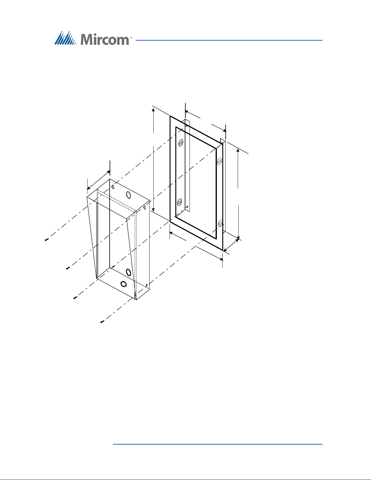
UNIVERSAL SLIM
LINE ENCLOSURE
TX3-USFT S L I M LINE
SEMI-FLUSHTRIM
6 13/32 "
8
7/8"
16 1/4"
19
5/8"
2 3/4"
4 1/2 "
Dimension of the Universal Slim Line Enclosure
without the flush trim is:
16.25” H x 6.4”W x 2.75“D at bottom, 3” D at top
The Universal enclosure mounts inside the wall with or without the Universal
Series Flush Trim Ring TX3-USFT. The Trim Ring houses the universal series
enclosure as shown in Figure 2
Enclosure Installation
Figure 2. TX3-USFT Slim Line Universal Flush Trim Ring
To install the Universal Slim-line enclosure with or without the Flush
Trim Ring
1. Follow the instructions in section 2.2.1 using the Universal Slim-line
enclosure.
Version 3.7 Telephone Access System Installation and Operation Manual 27 (119)
LT-969 Copyright January 2017
2.2.3 Installing the Continental enclosure
10 3/8"
12"
Use the two side
slots for mounting
the box to the
wall stud
16 7/8"
18 1/2"
Cut out in wall should be :
16 7/8” H x 10 3/8”W x 3” D
Outside Frame dimensions are:
18 1/2”H x 12”W x 1/2” D
WALL
FRONT
OUTSIDE
FRAME
SIDE VIEW
BACKBOX
MOUNTING
KNOCKOUTS
3.0 ”
0.5 ”
TOP
The Continental enclosure back box must be
flush mounted with wall
GROUND
SCREW
LOCATION
The Continental enclosure flush mounts directly inside the wall to the wall stud as
shown in Figure 3. Mount the back box flush with the wall and right-side up (the
ground screw location is at the bottom).
Enclosure Installation
28 (119) Telephone Access System Installation and Operation Manual Version 3.7
LT-969 Copyright January 2017
Figure 3. Continental Enclosure Flush Mount
To install the Continental enclosure
1. Find a suitable location for the Continental enclosure beside a wall stud.
2. Using the enclosure as a template, trace an opening in the wall for the cut
out with one side aligned with the side of the wall stud.
3. Cut an opening in the wall ensuring that one side is aligned with the wall
stud.
4. Insert the enclosure into the wall cutout and using the enclosure as a
template mark the top mounting hole location as shown in the side view in
Figure 3. Ensure that at least one side is beside a wall stud.
5. Remove the enclosure and place the screw halfway into the wall into the
marked hole location using the supplied screw.
6. Place the enclosure onto the top screw.
7. Screw the lower two screw at the bottom of the trim ring halfway into the
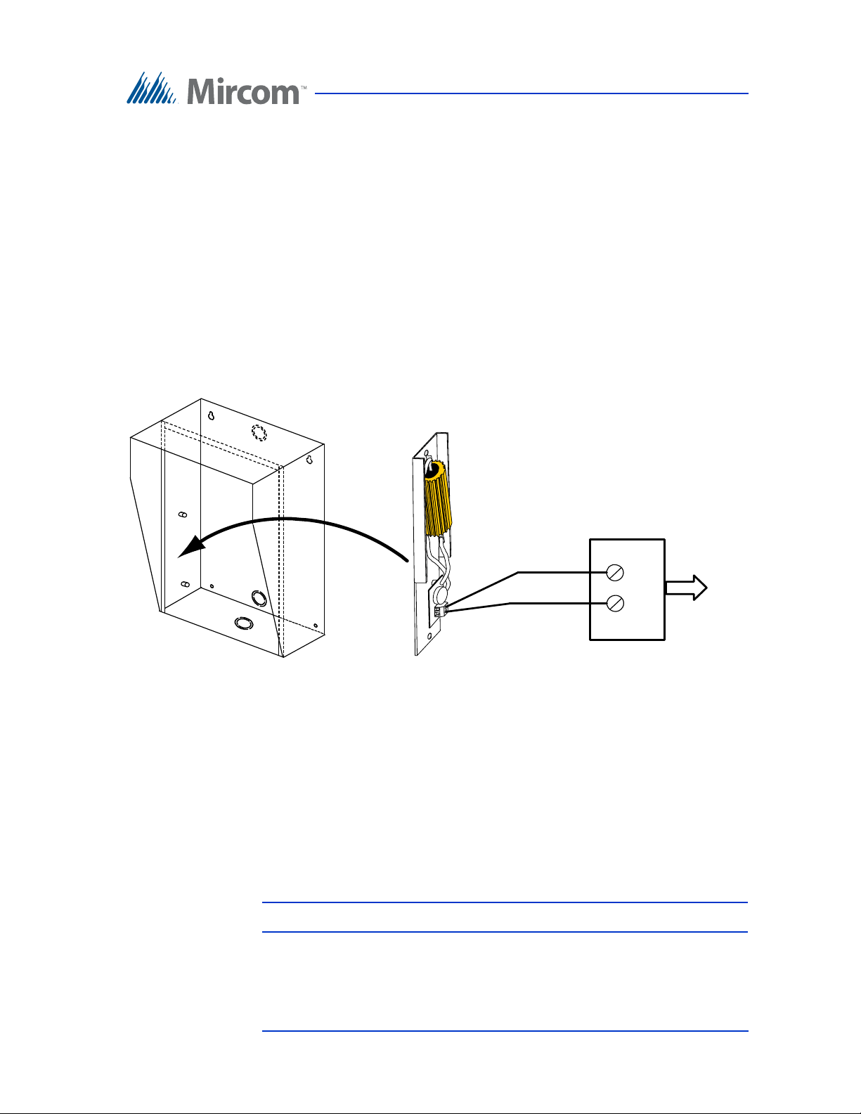
24V A C
PS-24 TRANSFORMER
18 AWG
TW ISTED PAIR
120V A C
60 HZ
UNIVERSAL
ENCLOSURE
TH-102 HE ATER
wall.
8. Tighten the two screws into place.
2.3 Installing the Heater
For temperatures where the Telephone Access System operates below 0°C
(32°F) at any time, a heater must be installed inside the Universal enclosure as
shown in Figure 4.
For additional information refer to LT-653 TH-102 Heater Installation
Instructions.
Enclosure Installation
Figure 4. Heater TH-102 Installation Location
To install the heater
1. Place the TH-102 Heater into the bottom left hand corner of the Universal
enclosure and secure using the two supplied spacers and two hex nuts.
2. Connect the TH-102 heater to the PS-24 Transformer 24 Vac terminal
screws using a pair of #18 AWG wires.
Note: The transformer must be installed outside the enclosure.
Version 3.7 Telephone Access System Installation and Operation Manual 29 (119)
LT-969 Copyright January 2017
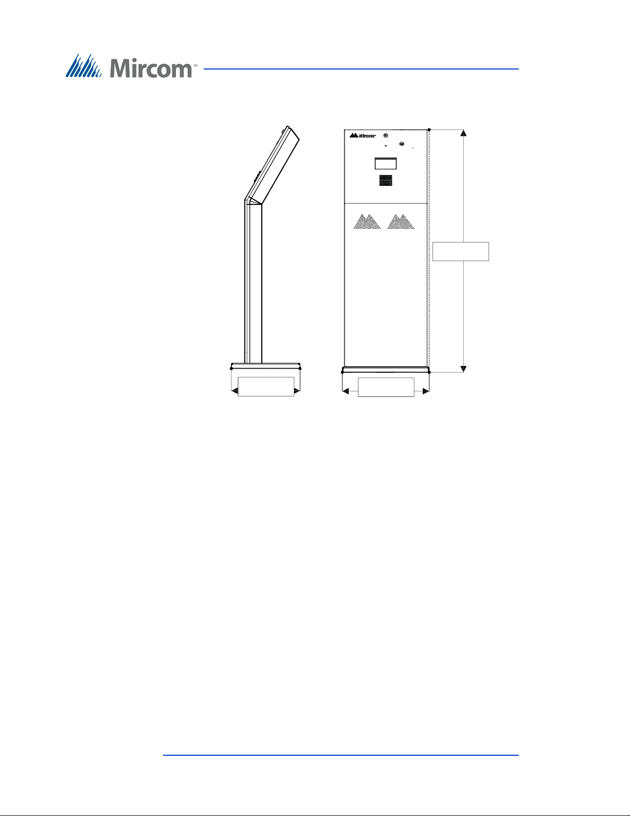
2.4 TX3-2000-8K-A Installation
50.117 "
17.950 "
14.187 "
Enclosure Installation
Figure 5 Dimensions of the 8 Line Kiosk (inches)
The Kiosk mounts to the floor inside the building near the entrance, close to the
power source and telephone infrastructure. Access for the power and
communication cables is provided through a cutout in the base plate.
To install the Kiosk you must:
• Remove the reinforcement bracket and the base plate.
• Attach the base plate to the floor, and run the wiring through the base plate
opening.
• Attach the Kiosk to the base plate.
• Attach the reinforcement bracket to the Kiosk.
Follow the instructions below to complete these steps.
You will need:
4 bolts to attach the base plate to the floor. The holes in the base plate are 0.406”
in diameter.
30 (119) Telephone Access System Installation and Operation Manual Version 3.7
LT-969 Copyright January 2017
 Loading...