

Page 1
60 750 228 1200 365 2000 609 3500 1066
Wiring Chart for 70V Speakers
Maximum Wiring Run To Last Device (ELR)
18AWG
16AWG
14AWG
MODELS
SSW-100 In-suite Silence Switch used with models: SP-404-70A and SP-504-70A
Maximum Number of Silenceable Speakers on a circuit is limited by the available
amplifier power.
SP-404-70A(W)
Directional Characteristic
and vertical axes)
SP-504SW-70A 79 dB
82 dB 85 dB 88 dB
TYPICAL OSPL (dBA)
SP-504-70A(W)
SSW-100
SP-404SW-70A(W)
SP-504SW-70A(W)
SMART SILENCEABLE SPEAKERS AND SUITE SILENCE SWITCH INSTALLATION INSTRUCTION
Designed to work with the QX-5000 Audio System using paging module QMP-5100A.
Compatible with MIRCOM’s SIS-204 Speaker Isolators.
Available in 4"round or 4" square front grill painted beige.
Mounts into MIRCOM’s standard speaker back boxes, IB-104, IB-204 and IB-404(W).
All smart silenceable speakers do not require a separate power supply.
Remote Silence switch model SSW-100 is used with silenceable speaker models SP-404-70A and SP-504-70A.
The SSW-100 mounts into a standard single gang electrical box. The red LED indicator follows the audio signal after the speaker is
silenced to indicate that an alarm is still active. A pushbutton switch is provided for local silencing of the in-suite speaker(s).
FOR DWELLING USE ONLY/ USAGE RÉSIDENTIEL SEULEMENT.
SP-404-70A(W) In-suite Silenceable 4" Speaker, Round, 70V
SP-404SW-70A(W) In-suite Silenceable 4" Speaker, Round, 70V with built-in Silence Switch
SP-504-70A(W) In-suite Silenceable 4" Speaker, Square, 70V
SP-504SW-70A(W) In-suite Silenceable 4" Speaker, Square, 70V with built-in Silence Switch
The suffix “W” indicates a bright white model.
SPEAKER ELECTRICAL SPECIFICATIONS
Input Voltage: 70V RMS
Speaker Coil Impedance: 8 Ohms
Power Taps: 0.25 W, 0.5 W, 1.0 W, 2.0 W
UL Frequency Range: 400 to 4000 Hz
Speaker Frequency Range: 320 to 11000 Hz
Indoor Operating Temperature: 32 EF to 120 EF (0 EC to 49 EC), For indoor use.
Standby Power: 0.0W
Power Consumption in Alarm: 0.25W plus(add) wattage of power tap selected.
SPEAKER 0.25 W
SP-404-70A 79 dB
SP-404SW-70A 78 dB
SP-504-70A 79 dB
0.5 W 1.0 W 2.0 W
82 dB 85 dB 88 dB
82 dB 84 dB 87 dB
82 dB 85 dB 88 dB
Meets or exceeds 75 dBA at 3m in an anechoic chamber using
indicated power tap per CAN/ULC-S541.
(representative of horizontal
Mircom does not recommend any changes to the factory applied
finish.
Total Power
Watts ft m ft m ft m ft m
15 2500 762 4000 1219 6000 1828 8000 2438
30 1500 457 2500 762 4000 1219 6000 1828
Wiring Method should be in accordance with CSA C22.1, Canada Electrical Code, Part I, Saftey Standard for Electrical Installations, Section 32.
Canada
25 Interchange Way
Vaughan, ON L4K 5W3
Tel: (888) 660-4655
(905) 660-4655
Fax: (905) 660-4113
U.S.A
4575 Witmer Industrial Estates
Niagara Falls, NY 14305
Tel: (888) 660-4655
(905) 660-4655
Fax: (888) 660-4113
Angle OSPL
90 (ref) 0 (ref)
± 20 -3 dBA
± 37 -6 dBA
± 90 -14.3 dBA
12AWG
LT-693 Rev.5
page 1
September 2016
Page 2
SP-404-70A(W)
SP-504-70A(W)
SSW-100
SP-404SW-70A(W)
SP-504SW-70A(W)
SMART SILENCEABLE SPEAKERS AND SUITE SILENCE SWITCH INSTALLATION INSTRUCTION
OPERATION: To silence speakers, push the silence switch and hold for 3 to 5 seconds until signals are silenced. When the
silence switch is activated, it will silence the connected speaker(s) for approximately 9 minutes before resounding. When a
paging message is initiated from the QMP-5100A, a 3 second pre-announce tone is used to reactivate the speaker(s) to
allow for the paging message to be heard. The silenced speaker will resound after the page is completed. In addition,
when the timer (9 minutes) expires, the speaker will resound if the alarm signal is still active. The speaker may be re-silenced in the same manner.
Note: The speaker must sound for 10 seconds before it can be silenced.
The speaker will return to “normal mode” (if previously silenced) automatically after the audio signal has ceased for more
than 30 seconds. If a subsequent alarm occurs prior to the 30 second time period (if previously silenced), the speaker will
not resound until the silence timer has elapsed. Any subsequent alarm that is processed after the fire alarm panel has
been silenced beyond the 30 second time period will sound the speaker immediately.
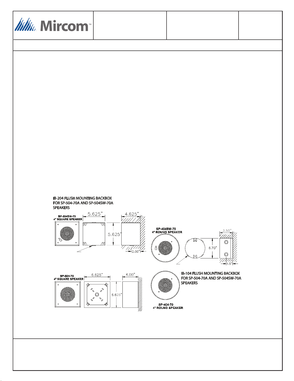
INSTALLATION: The speakers are mounted into their appropriate backboxes using 4 screws which are provided. These
boxes are usually mounted in the ceiling or in the wall. There is an IB-104 backbox (flush mount) which is used for the 4"
round speakers and there are two backboxes available for the 4" square speakers, IB-204 Flush Mount and IB-404(W)
Surface mount.
Canada
25 Interchange Way
Vaughan, ON L4K 5W3
Tel: (888) 660-4655
(905) 660-4655
Fax: (905) 660-4113
A
COMBINATION KNOCKOUTS
2 PLACES 1.125” 0.875”
A
IB-404(W) SURFACE MOUNTING
BACKBOX FOR SP-504-70A AND
SP-504SW-70A SPEAKERS
U.S.A
4575 Witmer Industrial Estates
Niagara Falls, NY 14305
Tel: (888) 660-4655
(905) 660-4655
Fax: (888) 660-4113
A
COMBINATION KNOCKOUTS
2 PLACES 1.125” 0.875”
A
LT-693 Rev.5
page 2
September 2016
Page 3

SP-404-70A(W)
SP-504-70A(W)
SSW-100
SP-404SW-70A(W)
SP-504SW-70A(W)
SMART SILENCEABLE SPEAKERS AND SUITE SILENCE SWITCH INSTALLATION INSTRUCTION
WIRING
Speaker Silencing using Silenceable Speakers with built in Silence Switch
The silenceable speakers SP-404SW-70A and SP-504SW-70A are wired in as in a standard speaker way. The silenceable
switch and alarm LED found on the front of these speakers are wired internally. All speakers wired within the silenceable
circuit with the suite will be silenced when the silence pushbutton is pressed. Refer to figure below for wiring information.
TO NEXT
NON-SILENCEABLE
STANDARD SPEAKER
(70V)
FROM QX-5000
70V AUDIO LINE
CONNECT TERMINAL S3 TO TERMINAL
S+ WITH WIRE PROVIDED WHEN USING
SINGLE SPEAKER IN-SUITE.
CONNECT THIS
BROWN WIRE TO
TAP SELECT:
EITHER 2, 1, ½, OR
¼ WATTS
DEVICE OR
END-OF-LINE
RESISTOR
OR RETURN
FOR CLASS A
Canada
25 Interchange Way
Vaughan, ON L4K 5W3
Tel: (888) 660-4655
(905) 660-4655
Fax: (905) 660-4113
Terminals S6, S7 and S8 are preconnected to the LED and Silence
Button on the front of this speaker.
GREEN CHASSIS WIRE
U.S.A
4575 Witmer Industrial Estates
Niagara Falls, NY 14305
Tel: (888) 660-4655
(905) 660-4655
Fax: (888) 660-4113
ELECTRICAL RATINGS:
RATING: FOR 70 VOLT SPEAKER LINES WITH 60
WATTS OF SPEAKER LOAD OR LESS.
ROOM SPEAKER LOAD
NOTE: CONNECT THE CHASSIS WIRE TO
THE SPEAKER BACKBOX FOR CHASSIS
GROUND. CHASSIS MUST BE CONNECTED
TO BUILDING GROUND AS PER CODE.
NOT PROVIDING PROPER GROUNDING
FOR SPEAKER WILL VOID WARRANTY.
: 6 WATTS MAXIMUM
LT-693 Rev.5
page 3
September 2016
Page 4

SP-404-70A(W)
SP-504-70A(W)
SSW-100
SP-404SW-70A(W)
SP-504SW-70A(W)
SMART SILENCEABLE SPEAKERS AND SUITE SILENCE SWITCH INSTALLATION INSTRUCTION
Speaker Silencing via in-suite Silence Switch SSW-100
The speakers may be silenced by installing an SSW-100 Silence Switch within the suite. The silenceable speakers
SP-404-70A and SP-504-70A are wired as shown below. The SSW-100 Silence is wired using three wire nuts.
NOTE: For speaker wiring size and length, refer to speaker instructions.
ORANGE
BLUE
SSW-100 SILEN CE
SWITCH AND LED
MOUNTED ON A
STANDARD SIGN AL
ELECTRICAL B OX
AND PLACED N EAR
SPEAKER(S) TO B E
SILENCED
DIAGRAM A
CONNECT
BROWN TAP:
WIRE TO
EITHER 2, 1, ½,
OR ¼ WATT
TERMINAL.
GREEN CHASSIS WIRE
NOTE: CONNEC T THE
CHASSIS WIR E TO THE
SPEAKER BACK BOX FOR
CHASSIS GROU ND. CHASSIS
MUST BE CONN ECTED TO
BUILDING GROU ND AS PER
CODE. NOT PRO VIDING
PROPER GROU NDING FOR
SPEAKER WIL L VOID
WARRANTY.
FIRE ALARM SIGNAL
PUSH TO SILENCE
BROWN TAP WIRE
BROWN
MARETTE AND
PLACE WITHIN
SPEAKER
BACKBOX
CONNECT
TO S +
SELECTED
FOR THIS
SPEAKER
TAP
C
C
TAP
C
C
MULTIPLE IN-SUITE SPEAKERS
IN-SUITE
SPEAKER
(70V)
FOR S6, S7 AND S8
WIRING SEE DIAGRAM A
}
TAP SELECTION: CONNECT
BROWN WIRE TO POWER TAP
REQUIRED FOR SPEAKER
ELECTRICAL RATINGS:
RATING: FOR 70 VOLT SPEAKER LINES WITH 60
WATTS OF SPEAKER LOAD OR LESS.
IN-SUITE SPEAKER LOAD
NON-SILENCEABLE
STANDARD SPEAKER
(70V)
TAP
IN-SUITE
SPEAKER
(70V)
C
-
FROM QX-5000
70V AUDIO LINE
+
: 6 WATTS MAXIMUM
TO NEXT
DEVICE OR
END-OF-LINE
RESISTOR
OR RETURN
FOR CLASS A
Silenceable Speakers with a Speaker Isolator:
The silenceable speakers may be isolated using a SIS-204 Speaker Isolator as shown in diagram below.
S4(-)
S5(-)
S1(+)
S2(+)
TO NEXT
DEVICE OR
END-OF-LINE
RESISTOR
RETURN TO QX-5000
AMPLIFIER FOR
CLASS “A” WIRING
-
+
FROM QX-5000
AUDIO LINE
FUSES: LITTELFUSE 0.1A, 250V SLOW BL OW #31 2.100
ELECTRICAL RATINGS:
RATING: FOR 70 VOLT SPEAKER LINES WITH 60 W ATTS OF SPEAKER LOAD OR LESS.
IN-SUITE SPEAKER LOAD
MAXIMUM NUMBER OF ISOLATORS ON A SPEAKER LINE:
Canada
25 Interchange Way
Vaughan, ON L4K 5W3
Tel: (888) 660-4655
(905) 660-4655
Fax: (905) 660-4113
S4(-)
S5(-)
S1(+)
SILENCEABLE
IN-SUITE SPEAKER
(70V)
S2(+)
JUMPERS REMOVED
SILENCEABLE
IN-SUITE SPEAKER
(70V)
-
NON-SILENCEABLE
NON-ISOLATED
SPEAKER (70V)
+
MODEL SIS-204 ISOLATOR
: 6 WATTS MAXIMUM
U.S.A
4575 Witmer Industrial Estates
Niagara Falls, NY 14305
Tel: (888) 660-4655
(905) 660-4655
Fax: (888) 660-4113
15 WITH SPECIFIED LITTELFUSE TYPE 312 FUSE.
© Mircom 2016
Printed in Canada
Subject to change without prior notice
www.mircom.com
NON-SILENCEABLE
NON-ISOLATED
SPEAKER (70V)
LT-693 Rev.5
page 4
September 2016
 Loading...