

Page 1
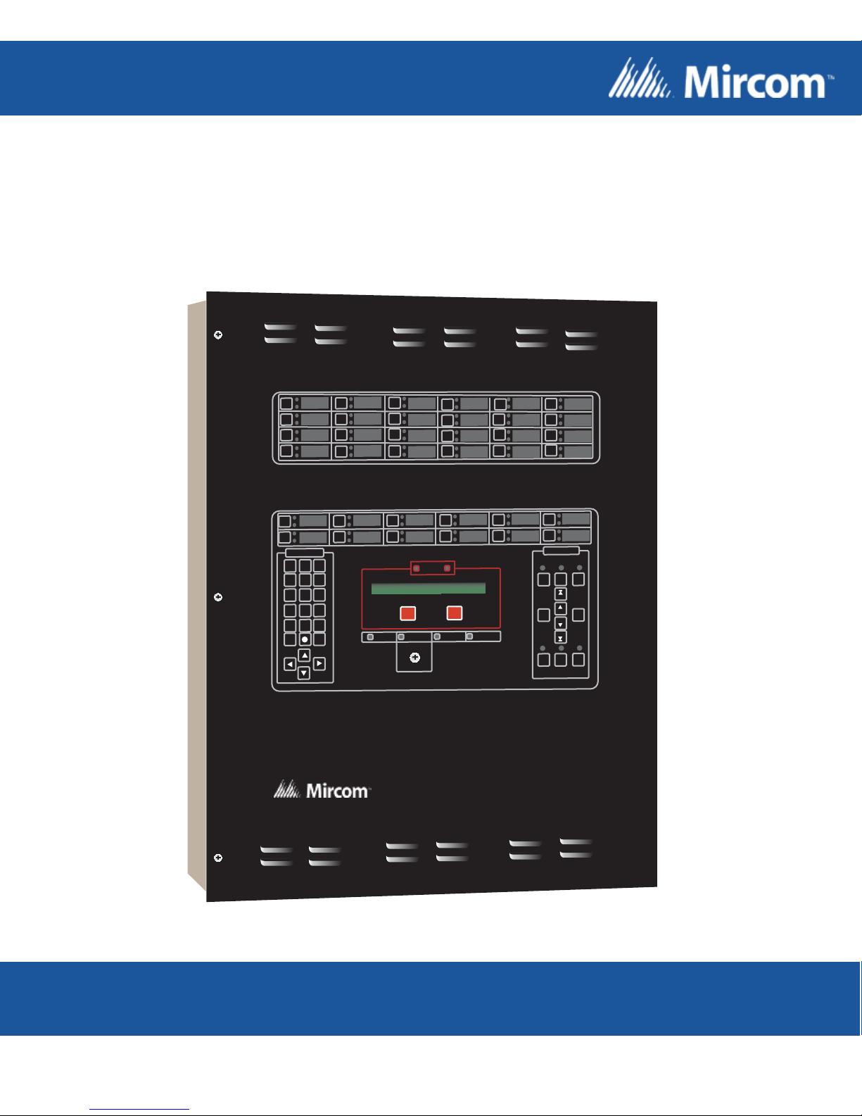
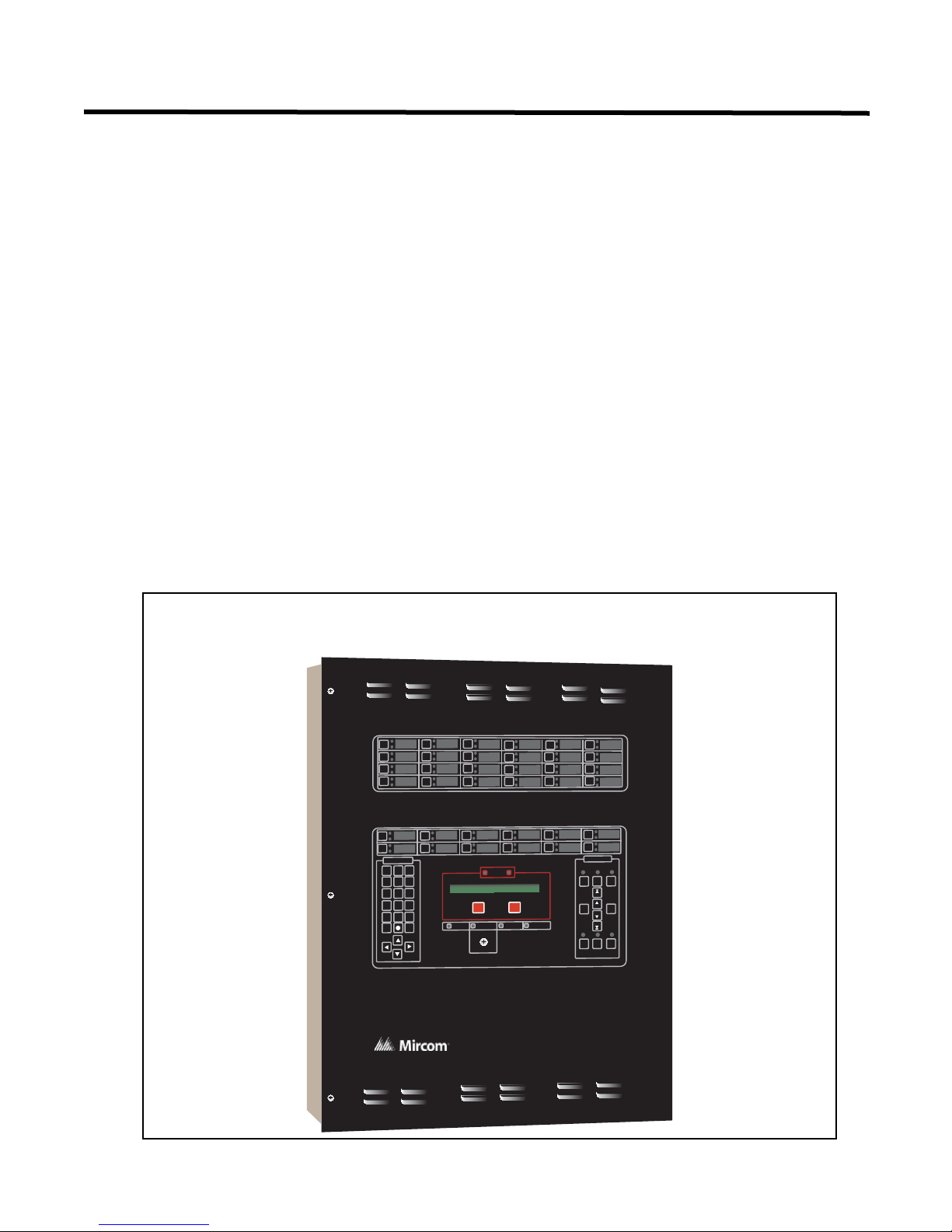
PRO-2000 Series
Addressable Fire Detection and Control System
SYSTEM DISP LAY
DEF
ABC
GHI
1 2 3
MNOJKL
4 5 6
VWXSTU YZ
7 8 9
* 0 #
CONTINUE
MENU
EXIT
PQR
ENTER
HELP
SUPERVISORY
CONTROLS
ENABLED
ALARM
SUPER-
TROUBLE
ALARM
VISORY
FIRST
PREV
LAMP
MORE
TEST
NEXT
PANEL
POWER ON
FAILED
LAST
ISOLATE
STATUS
SERVICE
Installation and Operation Manual
LT-1012 Rev 4.1
Feburary 2016
Page 2

Page 3

PRO-2000 Installation and Operation Manual
Table of Contents
List of Figures .......................................................................................................................... iii
List of Tables............................................................................................................................ iv
PRO-2000 Series ...................................................................................................................... 1
The User Interface................................................................................................................ 2
Features Table...................................................................................................................... 3
PRO-2000, X2 SERIES - S/E/M ................................................................................................ 4
PRO-2000 X2S (Standard)................................................................................................... 4
PRO-2000 X2E (Expanded) ................................................................................................. 4
PRO-2000 X2M (Mimic)........................................................................................................ 4
PRO-2000 X2, Common Features........................................................................................ 4
General Installation Guidelines............................................................................................. 5
Special Handling................................................................................................................... 5
Enabling the Onboard Lithium Battery Backup..................................................................... 6
Cable Entry and Internal Routing.......................................................................................... 6
Grounding and Bonding........................................................................................................ 7
Enclosure Installation. ... ........................................................................................................ 7
Hookup of AC Power and Batteries...................................................................................... 11
Alarm Supply ........................................................................................................................ 11
AC Power Connection .......................................................................................................... 11
Installing Batteries in the Enclosure...................................................................................... 12
PRO-2000, X6 SERIES - S/B/E/M............................................................................................. 14
PRO-2000 X6S (standard).................................................................................................... 14
PRO-2000 X6B (blank)......................................................................................................... 14
PRO-2000 X6E (expanded).................................................................................................. 14
PRO-2000 X6M (MIMIC) ...................................................................................................... 14
PRO-2000 X6 Common Features......................................................................................... 15
General Installation Guidelines............................................................................................. 15
Special Handling................................................................................................................... 15
Enabling the Onboard Lithium Battery Backup..................................................................... 15
Cable Entry and Internal Routing.......................................................................................... 15
Grounding and Bonding........................................................................................................ 16
Enclosure Installation. ... ........................................................................................................ 16
Hookup of AC Power and Batteries...................................................................................... 21
Alarm Supply ........................................................................................................................ 21
Installing Batteries in the Enclosure...................................................................................... 21
PRO-2000 X0 Series - S/E/M.................................................................................................... 23
General Installation Guidelines............................................................................................. 23
Special Handling................................................................................................................... 24
Cable Entry and Internal Routing.......................................................................................... 24
Grounding and Bonding........................................................................................................ 24
Enclosure Installation. ... ........................................................................................................ 24
PRO-2000 Multi-Panel Systems.............................................................................................. 31
MAIN PROCESSING CARDS................................................................................................... 34
MPU - Main Processing Unit card......................................................................................... 34
LCD - Liquid Crystal Display card......................................................................................... 38
X6 and X0 series .................................................................................................................. 39
EXPANSION CARDS ........................................................................................................... 43
Communication Card............................................................................................................ 44
APS-14127-00 Auxiliary Power Supply ................................................................................ 46
12 Zone Supervised OUTPUT Card..................................................................................... 49
24/32 Zone Supervised Input Card....................................................................................... 52
ADI - Addressable Device Interface card................................... .... ...................................... . 55
MIMIC Driver Module.............. ... ... ... .... ... ... ... ... .... ... ... ... ........................................................ 59
i
Page 4

Table of Contents
LCD Expander Card............................................................................................................. 60
External Devices.................................................................................................................. 61
OPERATING INSTRUCTIONS................................................................................................. 71
The LCD Panel..................................................................................................................... 71
DISPLAY.............................................................................................................................. 73
Operating Conditions.............................................................................................................. 74
Appendix A - Battery Calculations ........................................................................................ 93
Appendix B - Compatible Devices......................................................................................... 101
Warranty & Warning Information........................................................................................... 116
ii
Page 5

PRO-2000 Installation and Operation Manual
List of Figures
Figure 1: LCD Display ................................................................................................................................... 2
Figure 2: X2, Synoptic sketch of the PRO-2000, X2 series........................................................................... 5
Figure 3: Lithium Battery Jumper .................................................................................................................. 6
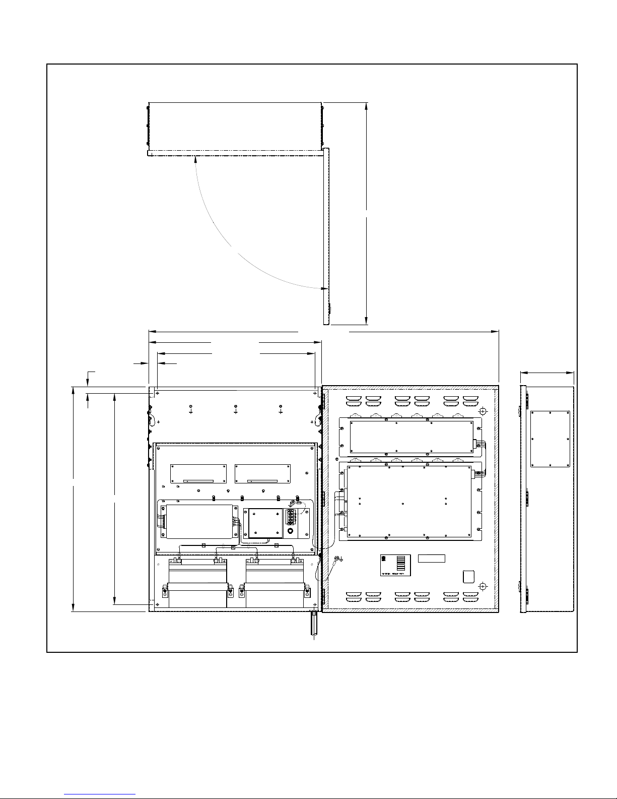
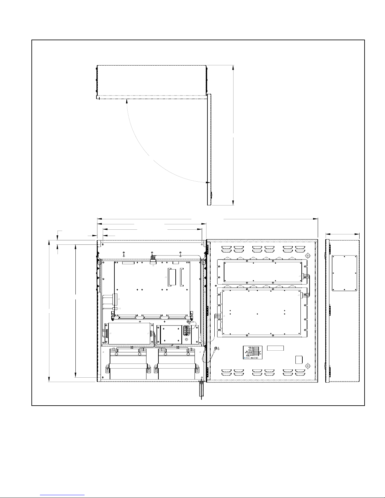
Figure 4: X2S, Installation Layout.................................................................................................................. 8
Figure 5: X2E, Installation Layout.................................................................................................................. 9
Figure 6: X2M, Installation Layout................................................................................................................. 10
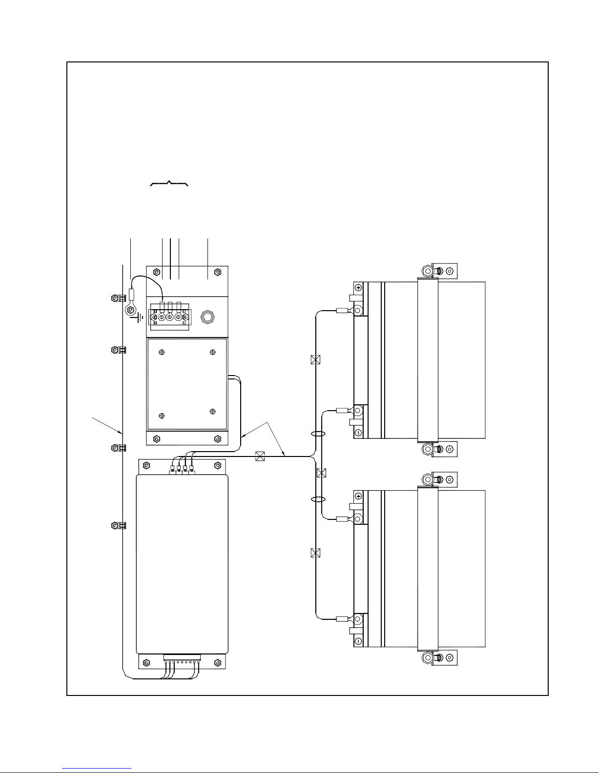
Figure 7: Terminal Connections .................................................................................................................... 12
Figure 8: Battery Hookup............................................................................................................................... 13
Figure 9: Synoptic Sketch of the PR0-2000, X6 Series................................................................................. 14
Figure 10: Micro-processor (MPU)..... ... ... .... ... .............................................................................................. 15
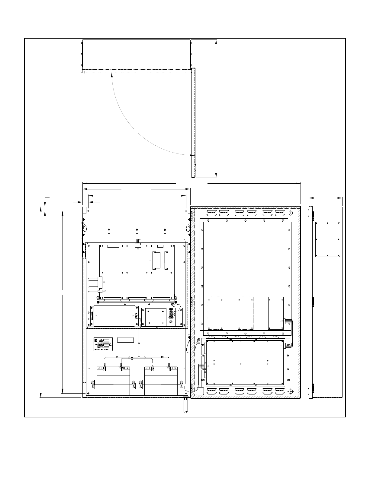
Figure 11: X6S, Installation Layout................................................................................................................ 17
Figure 12: X6B, Installation Layout................................................................................................................ 18
Figure 13: X6E, Installation Layout................................................................................................................ 19
Figure 14: X6M, Installation Layout.................................... ... .......................................... .... ... ... .................... 20
Figure 15: Battery Hookup..................... ... .... ... ... ... ... .... ... ... ... ........................................................................ 21
Figure 16: Synoptic Sketch of the PRO-2000, X0 Series.............................................................................. 23
Figure 17: X0S, Installation Layout................................................................................................................ 25
Figure 18: X0E, Installation layout................................ ... ... ... .... ... .......................................... ....................... 26
Figure 19: X0M, Installation Layout.................................... ... .......................................... .... ... ... .................... 27
Figure 20: X0S, Installation Layout with Power Supply and Batteries........................................................... 28
Figure 21: X0E, Installation Layout with Power Supply and Batteries........................................................... 29
Figure 22: X0M Installation Layout with Power Supply and Batteries........................................................... 30
Figure 23: PRO-2000 Networked Panels..... ... ... ... ... .... ... ... ... .... ... ... ... .... ... ... ... ... .... ... ... ... .... ... ....................... 31
Figure 24: X2 and X6 Network Wiring to a Repeater, X0.............................................................................. 32
Figure 25: Networking The X2 and X6 Using The Communication Card ...................................................... 33
Figure 26: MPU (Main Processing Unit) Card............................................................................................... 34
Figure 27: MPU Backplane Connectors........................................................................................................ 35
Figure 28: LCD Card ....................................................... ... ... .... ... ... ... .... ... ... ................................................. 38
Figure 29: LCD Backplane Connectors........ ... ... ........................................................................................... 38
Figure 30: Expansion Card and LCD Backplane........................................................................................... 40
Figure 31: Communication Card Connections............................................................................................... 44
Figure 32: Communication Card Wiring - Loop/Stub Mode........................................................................... 45
Figure 33: APS-14127-00 Auxiliary Power Supply....... ................................................................................. 46
Figure 34: APS-14127-00 Auxiliary Power Supply Connector ...................................................................... 47
Figure 35: APS-14127-00 Auxiliary Power Supply Typical Connection ........................................................ 47
Figure 36: APS-14127-00 Auxiliary Power Supply LED Indicators ............................................................... 48
Figure 37: 12 Zone Supervised Output Card................................................................................................. 49
Figure 38: Supervised Output Wiring ................. ... ... .... ... ... ... .... ... ... ... .... ... ... ... ... ........................................... 51
Figure 39:
Figure 40: Supervised Input Wiring.... ... ... .... ... ... ... ... .... ... ... ... .... ... ... ... .... ... ... ... ... .... ... ... ... .... .......................... 54
Figure 41: ADI - Addressable Device Interface Card and Connections ........................................................ 55
Figure 42: ADI Driver Module........................................................................................................................ 55
Figure 43: ADI Card Wiring - Stub and Loop Mode....................................................................................... 57
Figure 44: ADI Card Wiring - Supervised Relay Outputs .............................................................................. 58
Figure 45: MIMIC Driver Module and Connections ............ ... .... ... ... ... .... ... ... ... ... .... ... ... ... .... ... ... ... ... .... ... ....... 59
Figure 46: LCD Expander Card and Connections........................................ ... ... .... ....................................... 60
Figure 47: 2 Wire Class B Initiating Circuit Configuration of Monitor Module................................................ 62
Figure 48: 2 Wire Style B Initiating Circuit Configuration of Monitor Module................................................. 63
Figure 49: Class B Indicating Circuit Wiring of Control Module..................................................................... 64
Figure 50: Typical Isolator Module Wiring - Using EOL Relay for Line Supervision...................................... 65
Figure 51: ADI CARD - Typical Wiring Diagram Number 1 for Control Module In Release Configuration.... 67
Figure 52: ADI CARD - Typical Wiring Diagram Number 2 for Control Module In Release Configuration.... 68
Figure 53: SI Card Typical Wiring Diagram for Releasing Circuit.................................................................. 69
Figure 54: SO Card Typical Wiring Diagram for Releasing Circuit................................................................ 70
Figure 55: LCD Panel.. ....................................... ... ... .... ... ... ... .... ... ....................................... .......................... 71
24/32 Zone Supervised Input Card.................................................................................... 52
iii
Page 6

PRO-2000 Installation and Operation Manual
List of Tables
Table 1: Table of features .................................................................................................................... 3
Table 2: MPU Pinouts .......................................................................................................................... 36
Table 3: MPU Relays ........................................................................................................................... 36
Table 4: MPU Switches ........................................................................................................................ 36
Table 5: MPU Jumpers ........................................ ... .... ... ... ... .... ...................................... .... ................... 37
Table 6: MPU LEDs .......................................................................... .... ... ... ... ... .................................... 37
Table 7: LCD Pinouts ........................................................................................................................... 41
Table 8: LCD Relays ............................................................................................................................ 41
Table 9: LCD Switches ......................................................................................................................... 41
Table 10: LCD Jumpers .............................. ... ... ... ... .... ... ... ... .... ...................................... .... ... ................ 42
Table 11: LCD LEDs ...................................................................... ... .... ... ... ... ... .... ... ............................. 42
Table 12: Communication card Pin outs ............................................................................................... 44
Table 13: Communication Card LEDs.......... ... ... ... ................................................................................. 44
Table 14: 12 Zone Supervised OUTPUT Card Pin outs - Screw Termination ....................................... 49
Table 15: 12 Zone Supervised OUTPUT Card Pin outs - DSUB Termination ....................................... 50
Table 16: External Power Supply Connections ..................................................................................... 50
Table 17: 12 Zone Supervised OUTPUT Card Jum pers ....................................................................... 50
Table 18: 12 Zone Supervised OUTPUT Card LEDs .. ... ... ... .... ... .......................................................... 50
Table 19: 24 Zone Supervised Input Card Pin outs .............................. ... ... ... ... .................................... 52
Table 20: 32 Zone Supervised Input Card Pin outs .............................. ... ... ... ... .................................... 53
Table 21: Supervised Input Card LEDs ................................................................................................. 53
Table 22: ADI Card Pin outs ........................................... ... ... .... ... ... ... .... ... ... ... ... .... ................................ 56
Table 23: ADI Card Jumpers .......... ... .................................................................................................... 56
Table 24: ADI Card LEDs ........... .... ... ... ................................................................................................. 56
Table 25: MIMIC Driver Module LEDs ............................... ... .... ... ... ... .... ... ... ... ....................................... 59
Table 26: MIMIC Driver Module LEDs............................. ... ... .... ... ... ... .... ... ............................................. 60
Table 27: LCD Expander LEDs.......... ... ... .... ... ... ... ... .... ... ... ... ................................................................. 60
Table 28: System Status ...................... ....................................... ... ... .... ... ... ... ... .... ................................ 72
Table 29: Indicators and Push buttons from Display Panel ................................................................... 73
Table 30: PRO-2000 - Device ID .......................................... .......................................... .... ... ... ............. 76
Table 31: MIMIC Driver Module LEDs ............................... ... .... ... ... ... .... ... ... ... ....................................... 86
Table 32a: Device Trouble ...................... .... ... ... ... ... .... ... ... ... ................................................................. 88
Table 32b: Device Trouble (continuation) ............................................................................................. 89
Table 33a: Card Trouble ...................................... ... .... ... ... ... ................................................................. 90
Table 33b: Card Trouble (continuation) ............................................. .... ... ... ... ... .... ................................ 91
Table 33c: Card Trouble (continuation) ................................................................................................. 92
Table 34: Battery Capacity - Panel Specific Configuration ............................. ....... ...... ....... ...... ...... ....... 93
Table 35: X2 Panel Standby Current Consumption - Main Power Supply ............................ ... ... ... .... ... 94
Table 36: X2 Panel Standby Current Consumption - Battery back-up .................................................. 95
Table 37: X2 Panel Alarm Current Consumption - Battery back-up ...................................... ................ 96
Table 38: X6 Panel Standby Current Consumption - Main Power Supply ............................ ... ... ... .... ... 97
Table 39: X6 Panel Standby Current Consumption - Battery back-up .................................................. 98
Table 40: X6 Panel Alarm Current Consumption - Battery back-up ...................................... ................ 99
Table 41: System Components Current Consumption - External Power Supply .................................. 100
iv
Page 7

PRO-2000 Installation and Operation Manual
PRO-2000 Series
The PRO-2000 is a sophisticated micro-processor-based, fire detection, monitoring and control series of panels.
The panels are fully on-site configurable.
The number and type of PRO-2000 panels depend on your application. They come in different versions-a n X2,
X6, and X0-allowing system scalability. The X2 and X6 versions are the main building blocks of the PRO-2000
series, with the X0 version acting as remote annunciators.
The connected detection, monitoring, and control devices can be configured in loop or stub configurations. The
status of the devices can be displayed by a single panel or by multiple p anels in a network. In a network
configuration, one panel is programmed as a Master, with all other panels configured as Slaves-reporting alarms
and device states to the Master panel.
The panels are designed to operate as a stand-alone fire detection and control panels, or as part of a network,
comprising several PRO-2000 panels, with a total capacity of 10,000 I/O points. The PRO-2000 panel performs
trend analyses of the measured values obtained from monitored sensors and adjusts individual alarm thresholds
to compensate for detector contamination or slow-changing environmental influences. These analyses ensure
reliable determination of the status (alarm, fault, or normal).
The basic configuration of a PRO-2000 panel comprises three main elements:
• An Enclosure containing the electronics necessary to run the system.
• A PRO-2000 panel may contain a combination of up to two expansion cards for the X2 series, and six
expansion cards for the X6. For example, Addressable Devices Interface (ADI), Communication, Supervised
Input, and Supervised OUTPUT cards. The enclosure size and contents depend on the configuration of your
protected installation.
• A Power Supply connecting to an external power source as well as Battery charger/Battery backup capability.
• A user interface between the system and the operator equipped with LED indica to rs, push button s, a Contr ol
Key Switch, and a Liquid Crystal Display (LCD).
• All PRO-2000 panels provide a 2 x 40 character, backlit, LCD display indicating the status (alarm, fault, or
normal) of each of the devices. The Expanded versions, X6E, X2E, and X0E pan els provide additional control
and display capabilities with the addition of 24 push buttons and 48 LEDs.
The panels can act as releasing units for applications where different extinguishing agents are used. A typical
releasing configuration comprises heat or smoke detectors, a pull station, an abort station, a set of extinguishant
cylinders, and audible/visual signaling devices. The p anel is factory programmed to meet the necessary
requirements for each zone.
Applicable Standards: NFPA 11, 12, 12A, 12B, 13, 15, 16, 17, 17A, 70, 72, 750, 2001
UL 864 Rev. 9, ULC S524, ULC S527-99
1
Page 8
PRO-2000 Series
ALARM
VWXSTU YZ
EXIT HELP
8
0
CONTINUE
#
MENU
7
ENTER
*
9
DEF
MNO
5
2
JKL
4
ABC
1
PQR
6
GHI
3
SYSTEM
SUPERVISORY
ENABLED
CONTROLS
RESET
SERVICESTATUS ISOLATE
POWER ON
FAILED
PAN EL
ACKNOWLEDGE
NEXT
LAST
PREV
FIRST
TEST
LAMP
MORE
VISORY
SUPER-
ALARM TROUBLE
DISPLAY
USER DEFINED SECTION
LCD DISPLAY - USER DEFINED MESSAGES
SYSTEM KEY PAD
CONTROL KEY SWITCH
USER CONTROL SECTION
DYSPLAY KEY PADBUZZER
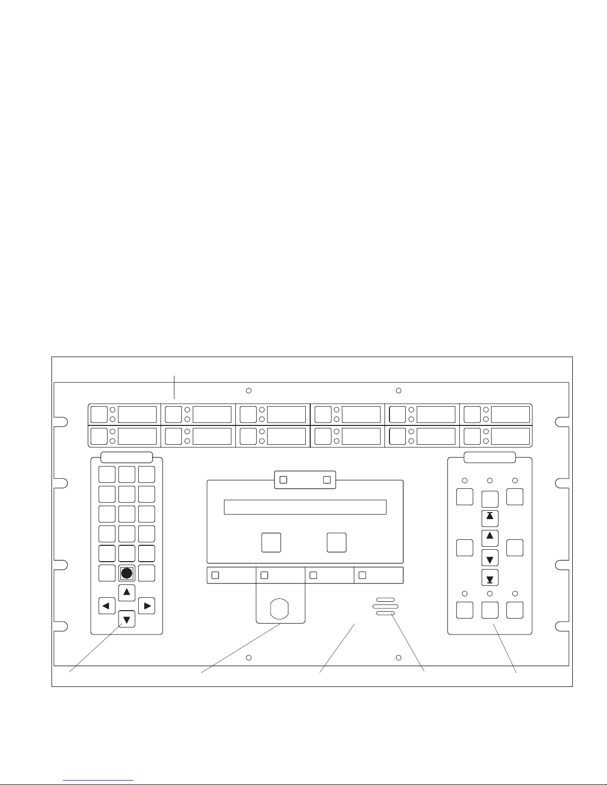
The User Interface
Mounted on the enclosure door, the LCD Display provides the user interface for the PRO-2000. The LCD Display
comprises an LCD card, a display/control escutche on with configu rable LEDs and push buttons, control key switch,
and a buzzer.
The built-in buzzer draws attention to the pane l on occurrence of any detected event. The buzzer sounds
intermittently at two different rates: fast for alarms and slow for all other conditions.
The display/control escutcheon interfaces between the operator and the panel. There are 4 sections:
•The Display section provides selectable display lists of the events you want to access. By selecting a Mode,
Alarm, Supervisory, Trouble, Status, Service or Isolate, the appropriate list appears in the LCD.
•The System section provides selections for system maintenance. For example, enable/disable printing, print
the event log, place/remove devices into/from service or isolate mode.
•The User Defined section contains 12 configurable push butto ns and 2 4 status LEDs-one red and one yellow
for each push button.
•The User Control section displays events and provides acknowledge and reset features.
Membrane push button controls acknowledge and silence alarms, reset the detection circuits, and test the panel
display. These controls also enable authorized service personnel to perform service functions. Using the System
keypad, the operator can select different maintena nce functions such as the event log, backlighting intensity, and
other maintenance related features.
The LCD Display features a 2 line by 40 character Liquid Crystal Display (LCD) indicating the status of the panel
and all connected input and OUTPUT devices. When an off-normal condition occurs, the first line displays event
occurrence and time, the second line provides a plain language description of the off-normal condition. The text
description for the zone or device is user-defined.
2
Figure 1: LCD Display
Page 9

Features Table
PRO-2000 Installation and Operation Manual
USCG
UL/
ULC
XX
XX
XX
XX
XX
XX
XX
XX
XX
XX
XX
XX
XX
XX
XX
XX
XX
XX
XX
XX
XX
XX
XX
XX
XX
XX
XX
Feature X2S X2E X2M X6S X6E X6M X6B X0S X0E X0M
Listing XXXXXXXXXX
Up to 1200 local detection/control devic es/zones
per panel
Up to 3600 local detection/control devic es/zones
per panel
Up to 5000 networked detection/control zones
per panel
Up to 10000 networked detection/control zones
per panel
Support for addressable devices (detectors,
monitor modules, control modules)
Support for conventional 2-wire initi ating devices
(shouting and non-shorting devices)
Support for notification circuits (dry conta cts and
supervised outputs)
Support for panel networking RS-422 loop/stub XXXXXXXXXX
Support for Printer, MODBUS interface,
diagnostic port RS-232 with or without
handshake
Support for repeater panels XXXXXX
User interfaces:
- 2 lines x 40 characters backlit LCD display,
- 24 programmable local LED indicators,
- 12 programmable local push buttons,
- Easy one key access to display lists, Alarm,
Supervisory, Trouble, Status, Service, Isolate
Adjustable panel brightness XXXXXX XXX
One person walk test XXXXXX XXX
Service and isolate modes XXXXXX XXX
Battery back-up real time clock and event log XXXXXX XXX
110 to 120VAC or 220 to 240VAC operation XXXXXXXXXX
Battery charger XXXXXXXXXX
Master Alarm and Trouble Relays XXXXXXX
All field wiring connected through removable
connectors with screw terminators
Isolated power supplies on each interface card
for exceptional noise immunity
Independent Ground fault detection circuits on
each interface card for easy Ground fault
tracking
Transient protection on all f ield con nect ions and
chassis
Wall mount enclosure XXXXXXXXXX
48 additional programmable local indicators X X X
24 additional programmable local push buttons X X X
Geographic mimic display containing up to 144
indicators (LED) and 72 push buttons
Table 1: Table of features
XXX
XXXX
XXX
XXXX
XXXXXXX
XXXXXXX
XXXXXXX
XXXXXXX
XXXXXX XXX
XXXXXXXXXX
XXXXXXXXXX
XXXXXXXXXX
XXXXXXXXXX
XX X
3
Page 10

PRO-2000, X2 SERIES - S/E/M
PRO-2000, X2 SERIES - S/E/M
The PRO-2000 X2 Series are fire alarm monitoring and control units suitable for small to medium applications.
Large applications can be covered with networked panels.
The PRO-2000 X2 Series consists of three types of panels: the X2S, the X2E, and the X2M.
PRO-2000 X2S (Standard)
The X2S is the standard panel housed in a 23” x 24” (584 mm x 610 mm) enclosure. The X2S consists of a
processing and display unit which processes all field data and displays all event. It has the standard 2 lines by 40
character display with the associated display list controls and indicators and the standard 24 configurable indicators
(LEDs) and 12 configurable push buttons.
PRO-2000 X2E (Expanded)
The X2E is the expanded version housed in a 24” x 30” (610 mm x 76 2 mm) enclosur e. It has th e same fe atures as
the X2S plus an additional 48 configurable indicators (LEDs) and an additional 24 configurable push buttons.
PRO-2000 X2M (Mimic)
The X2M is the mimic version housed in a 24” x 41” (610 mm x 1041 mm) enclosure. It has the same features as
the X2S plus a geographic mimic providing a graphical representation of the protected area. The mimic contains up
to 144 indicators (LEDs) to provide visual feedback and 72 programmable push buttons.
PRO-2000 X2, Common Features
The X2 Series supports communication and n etworking functions. The X2 panels can operate as standalone panels
or they can be networked in a master/slave configuration. The master can be programmed to monitor and control
the slave panels as well as monitor its own devices.
By adding an RS-232 communication module to the LCD card, the X2 panels can communicate with external
devices, such as printers or computers, via a standard modular phone jack. The RS-232 communication module
supports one channel. By adding an RS-422 communication module, the X2 panels can be networked to other
PRO-2000 panels. The RS-422 communication module supports 2 channels. The communication capabilities of the
X2 Series can be further expanded by the addition of Communication cards.
The printer used must be UL ITE Listed. ITE stands for Information Technology Equipment as per UL requirement.
The X2 panels can be expanded using up to 2 of the following expansion cards:
• Addressable Detector Interface (ADI) card - smoke/heat detectors, monitor modules, control m odules, and 4 on
board supervised/unsupervised outputs
• 24/32 Zone Supervised Input (SI) card - conventional detectors, shorting and non-shorting devices
• 12 Zone Supervised OUTPUT (SO) card - supervised outputs and dry contacts
• Communication Card - networked configurations
4
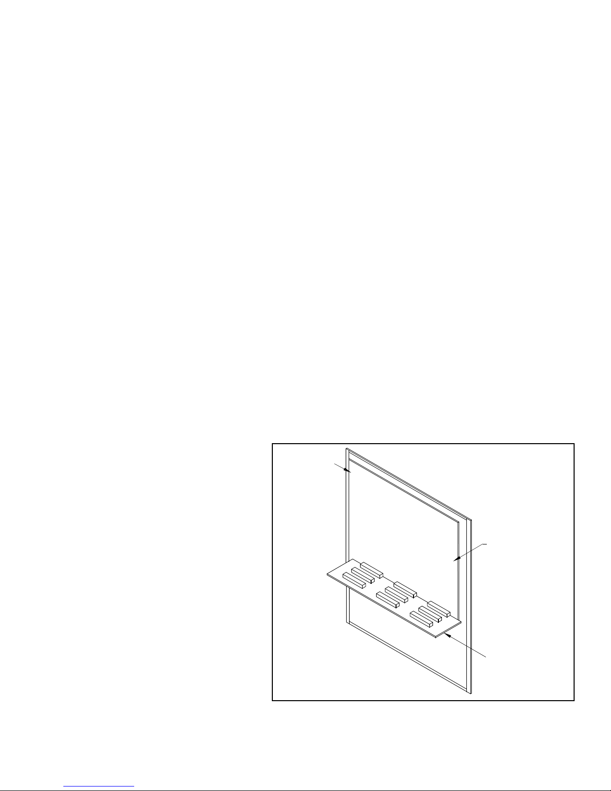
Page 11
PRO-2000 Installation and Operation Manual
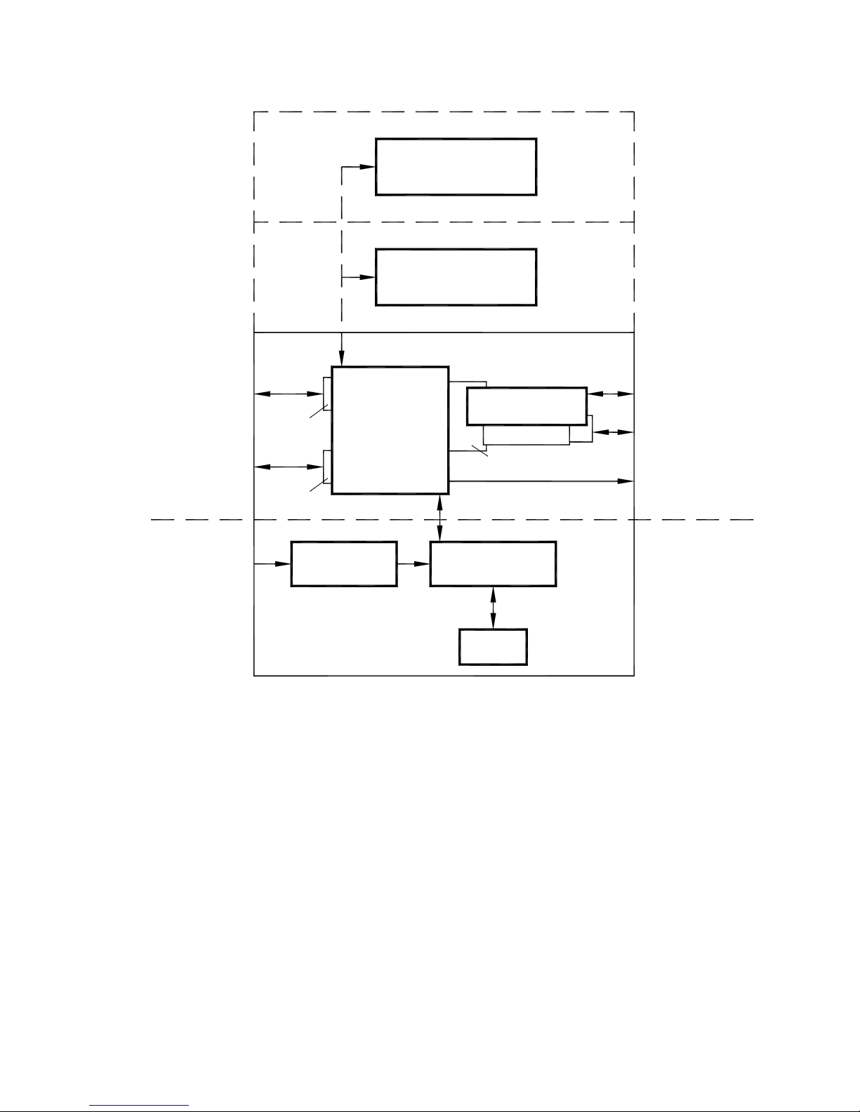
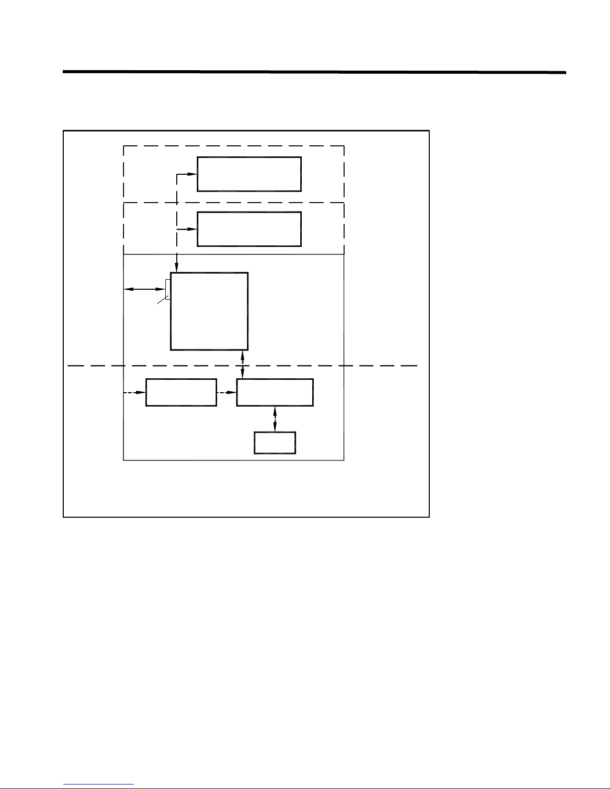
Geographic MIMIC
(MIMIC driver)
LCD expander
Processing and
Display Unit
(LCD)
Expansion cards
(Up to 2)
Transformer
115 or 220 VAC
Power supply
and
battery charger
Batteries
X2M
X2E
X2S
Power-Limited
Circuit
Detection and
Signaling
Communications
Master Alarm and
Fault Relays
Non Power-Limited
Circuit
Backplane
Networking
(RS-422)
Printer (RS-232)
AC Power
RS-422
Module
Module
RS-232
Circuits
General Installation Guidelines
X2 panels should be installed in a dry, clean, well lit secured area. No combustible or hazardous material should
be stored in the vicinity of the installed unit. The installation must comply with all local and/or national regulations
and codes of practice governing fire alarm system installation, electrical wiring, life safety, etc.
Special Handling
Circuit cards are to be stored in anti-static packaging and kept away from the sun and from direct sources of
intense UV light. The circuit card may be subject to degradation due to electrostatic discharge; therefore
grounding straps must be worn when handling the cards.
Figure 2: X2, Synoptic sketch of the PRO-2000, X2 series
5
Page 12

PRO-2000, X2 SERIES - S/E/M
LCD
JUMPER
LITHIUM BATTERY
Enabling the Onboard Lithium Battery Backup
The X2 panels are shipped with the jumper for the lithium battery disconnected. You must insert the jumper to
activate the battery backup for the real time clock and the RAM memory used for the event log. Jumper is located
on the LCD (JP6).
Cable Entry and Internal Routing
On the enclosure there are two removable cable entry plates. These plates are to be remove d, punched and reinstalled. If additional entry holes are required outside the cable entry plates, before punching cable entry holes:
1. Disconnect the wiring harness from the power supply to the LCD card.
2. Disconnect the door ground strap and remove the enclosure door with attached electronics.
3. Remove the mounting plate with attached power supply from the enclosure base.
Cable entry holes must be punched in accordance with the following criteria:
• Separate holes are required for the entry of Power-Limited and Non -Power-Limited circuit cables.
6
Figure 3: Lithium Battery Jumper
Page 13

PRO-2000 Installation and Operation Manual
• Centre-to-centre spacing between an entry hole for Power-Limited circuit cables and an entry hole for NonPower-Limited circuit cables must not be less than two (2) times the diameter of the larger entry hole.
• Sufficient clearance must be provided around each hole to allow for any required conduit fittings, cableclamps, lock nuts, washers or other hardware.
• Exclusive entry holes must be provided for the Primar y AC Supply cab le and for the External Standby Supply
(battery backup) cable.
• At no point inside the enclosure must the spacing between power-limited and non-power-limited circuit
conductors be less than 6.4mm (114 inch).
Wire length inside the enclosure should be kept to a minimum.
Cables must not interfere with, or touch any circuit card components other than the intended co nnector terminals.
Grounding and Bonding
All supply and device wiring must be grounded and bonded in accordance with applicable local regulations governing the wiring of
Fire Alarm Systems.
Enclosure Installation
All cable entry holes should be punched out prior to installation of base.
Ensure wall or structure to which the enclosure base is being mounted is capable of su pporting a fully loa ded unit.
Sufficient clearance must be provided around the unit to allow the enclosure cover door to be fu lly opened (180° )
without impediment. The enclosure box may be semi-flush mounted provided no less than 5 cm (2 inches) of the
box frame protrudes from the wall surface.
The top of the enclosure should be no more than 2.0 meters (6.7 feet) above the finished floor.
Recommended mounting hardware: four 1/4” pan head screws (if bolts are used, four suitable flat washers are
required).
1. Remove the ground strap (14 gauge, green) between the enclosure base and door by loosening and removing
the ground stud nut and star washer.
2. Disconnect the power harness connectors at J5 and J7 on the LCD card.
3. Remove the enclosure door from th e slip hin g es .
4. Remove the mounting plate, with attached power supply, from the enclosure base.
5. Secure the enclosure to wall using the for ¼“ panhead screws.
6. Align the mounting plate, with attached power supply, to the enclosure base threaded studs and secure with
attaching nut and washer.
7. Re-install the door and ground strap between the door and the enclosure base.
8. Reconnect the power harness connectors at J5 and J7 on the LCD card.
7
Page 14
PRO-2000, X2 SERIES - S/E/M
J2 J1
J11J10
J12
1
2
E
S
F
U
F
.
E
S
U
F
.
E
F
.
U
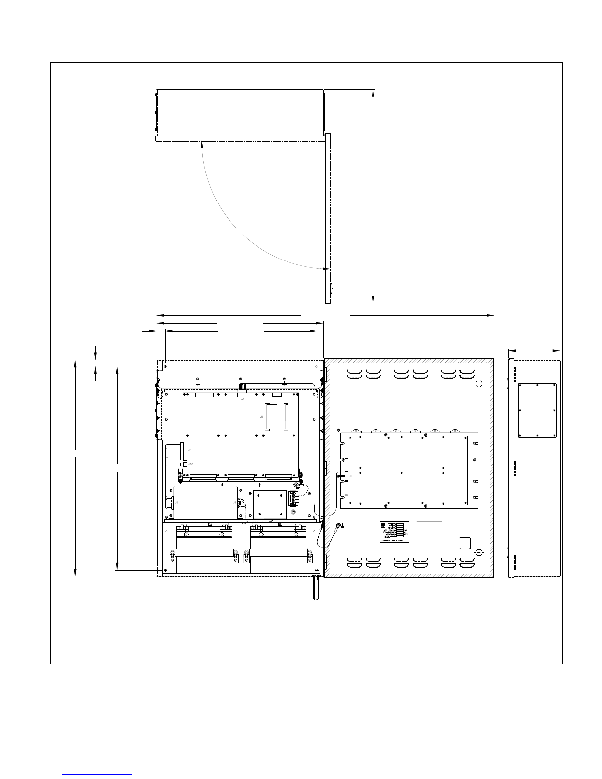
23.10" [586.74mm]
24.00" [609.60mm]
7.16" [181.94mm]
21.00" [533.40mm]
22.20" [563.88mm]
1.20" [30.48mm]
46.76" [1187.60mm]
90°
29.68" [753.92mm]
+-
-
+
0.90" [22.86mm]
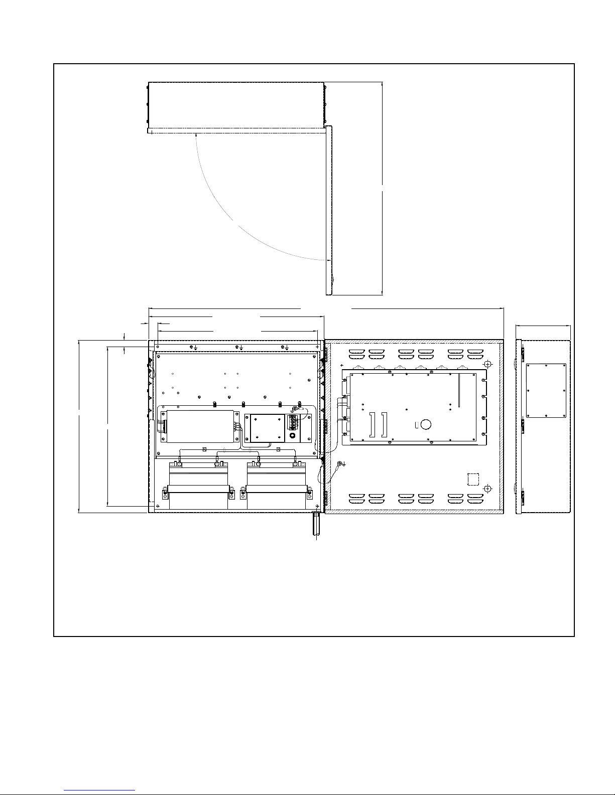
Figure 4: X2S, Installation Layout
8
Page 15
PRO-2000 Installation and Operation Manual
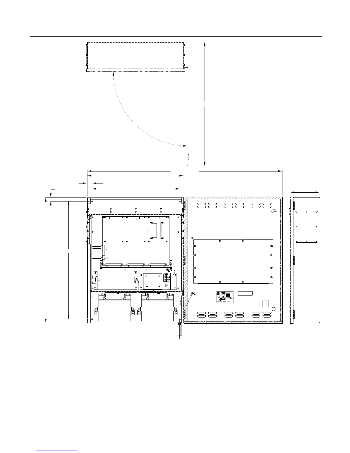
7.16" [181.97mm]
J2
J2
INPUT FREQUENCY:
INPUT VOLTAGE:
POWER LIMITED:
FUSE RATING:
OUTPUT
AMPS
V.AC
HZ
PART NO:
SERIAL NO:
MODEL NO:
J1J2
J7
J5
21.00" [533.40mm]
1.20" [30.48mm]
23.10" [586.74mm]
46.76" [1187.60mm]
28.20" [716.28mm]
0.90" [22.86mm]
30.00" [762.00mm]
90.00°
29.68" [753.92mm]
E
F
U
F
.
F
.
U
S
E
.
F
U
S
E
Figure 5: X2E, Installation Layout
9
Page 16
PRO-2000, X2 SERIES - S/E/M
7.16" [181.97mm]
90.00°
29.68" [753.92mm]
0.90" [22.86mm]
39.20" [995.68mm]
41.00" [1041.40mm]
1.20" [30.48mm]
23.10" [586.74mm]
46.76" [1187.60mm]
21.00" [533.40mm]
Figure 6: X2M, Installation Layout
10
Page 17

PRO-2000 Installation and Operation Manual
Hookup of AC Power and Batteries
The Power Supply provides a regulated 28 VDC to the PRO-2000 series and provides charge current to the
optional backup batteries. As the batteries are kept permanently charged, power is continuously provided
(Uninterruptible Power Supply or UPS). The power supply AC rat ing s ar e as fo llow s:
120 V version: V = 120 VAC nominal, I = 1.5 A, frequency 60 Hz
220 V version: V = 220 VAC nominal, I = 0.8 A, frequency 50 Hz
LEDs are visible on the Power Supply indicating the functional status of the unit. As the Power Supply is
convection cooled, no fans or blowers are required. The transformer and power supply mount directly on the
mounting plate.
A built-in battery charger maintains the batteries at full capacity. After extended power outages, the charger
restores the batteries to full capacity. Short circuit, over-voltage, and brownout monitoring circuits protect all
powered components by switching to the batteries whenever a tr ouble condition exists in the power supply.
Alarm Supply
Power to the alarm devices in a system must be supplied from a separate battery backed-up Power Supply which
is "UL listed (ULC listed in Canada)" for fire protective signal system use.
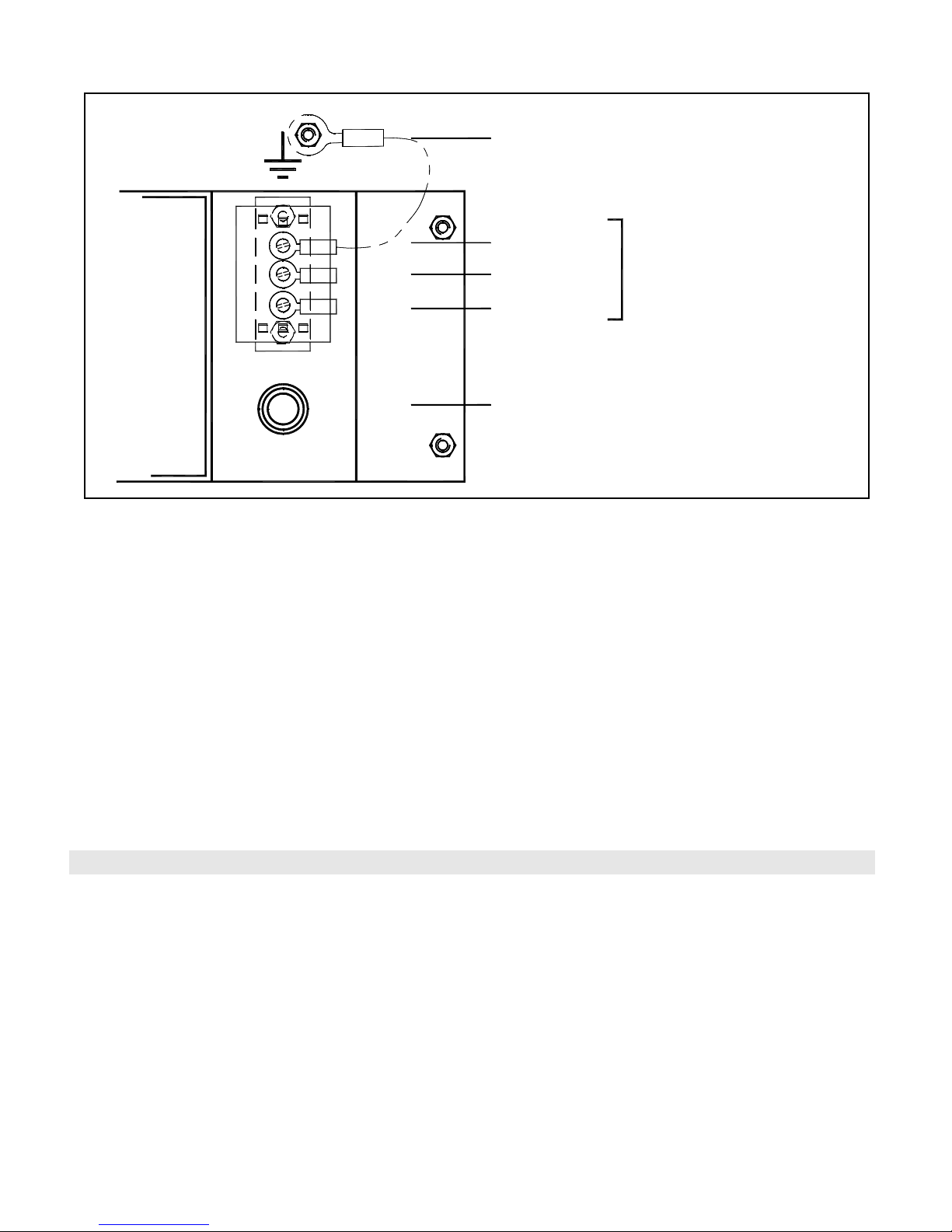
AC Power Connection
CAUTION: Ensure all voltage sources are disconnected from the panels before installing or removing cards.
1. Remove terminal cover from terminal block, TB1, located on the transformer bracket.
2. Connect Primary supply Ground wire (green) to Ground stud.
3. Connect Primary supply Neutral wire (white) to TB1 NEUTRAL terminal.
4. Connect Primary supply Line wire (black) to TB1 LINE terminal.
5. Replace and secure terminal cover on TB1.
6. Maximum 150 VAC to Ground.
11
Page 18
PRO-2000, X2 SERIES - S/E/M
S
.
F
E
.
F
U
F
E
U
E
.
F
U
S
GROUND
NEUTRAL
LINE
GROUND STUD
FUSE
NON POWER
LIMITED CIRCUIT
Figure 7: Terminal Connections
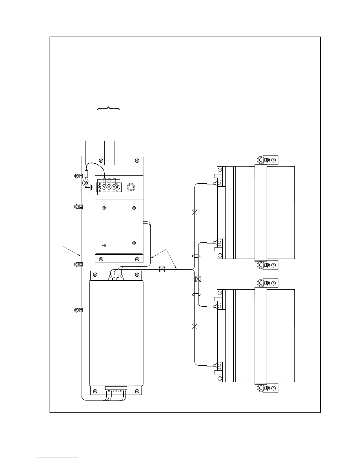
Installing Batteries in the Enclosure
The following instructions apply only to systems requiring 42 Amp-Hours or less of battery back-up capacity.
1. Remove battery retaining hardware.
2. Place two new fully charged 12V batteries on the bottom of the enclosure. Use 12V sealed lead-acid batteries.
3. Connect jumper between the batteries 'A' and 'B' poles (see Figure 8).
4. Connect black wire terminal to battery 'A'.
5. Connect red wire terminal to battery 'B' (+).
6. Replace battery and secure with retaining hardware.
For the Calculation of Battery Requirements, refer to Appendix A.
12
Page 19
C
I
R
C
U
I
T
S
N
O
N
P
O
W
E
R
-
L
I
M
I
T
E
D
C
I
R
C
U
I
T
S
N
O
N
P
O
W
E
R
-
L
I
M
I
T
E
D
B
F
U
S
E
(
F
1
)
L
I
N
E
N
E
U
T
R
A
L
G
R
O
U
N
D
S
T
U
D
G
R
O
U
N
D
A
J
U
M
P
E
R
P
O
W
E
R
-
L
I
M
I
T
E
D
C
I
R
C
U
I
T
R
E
D
B
L
A
C
K
U
F
E
.
F
U
S
E
.
F
U
F
S
E
J
1
J
2
Figure 8: Battery Hookup
PRO-2000 Installation and Operation Manual
13
Page 20
PRO-2000, X6 SERIES - S/B/E/M
Addressable Fire Detection and Control System
AL
ARM
SY
STEM DISPLAY
123
456
789
*0#
EXIT
HELP
CONTINUE
MENU
ENTER
SUPERVISORY
ENABLED
CONTROLS
POWER ON
FAILED
PANEL
NEXT
LAST
PREV
FIRST
TEST
LAMP
MORE
VISORY
SUPER-
ALARM
TROUBLE
SERVICE
STATUS
ISOLATE
VWXSTU YZ
DEF
MNOJKL
ABC
PQR
GHI
PRO-2000, X6 SERIES - S/B/E/M
The PRO-2000 X6 panels are fire alarm monitoring and con trol unit s suit able for medi um to large application s. Very
large applications can be covered with networked panels.
The PRO-2000 X6 Series consist of four types of panels: the X6B, the X6E, the X6M and the X6S.
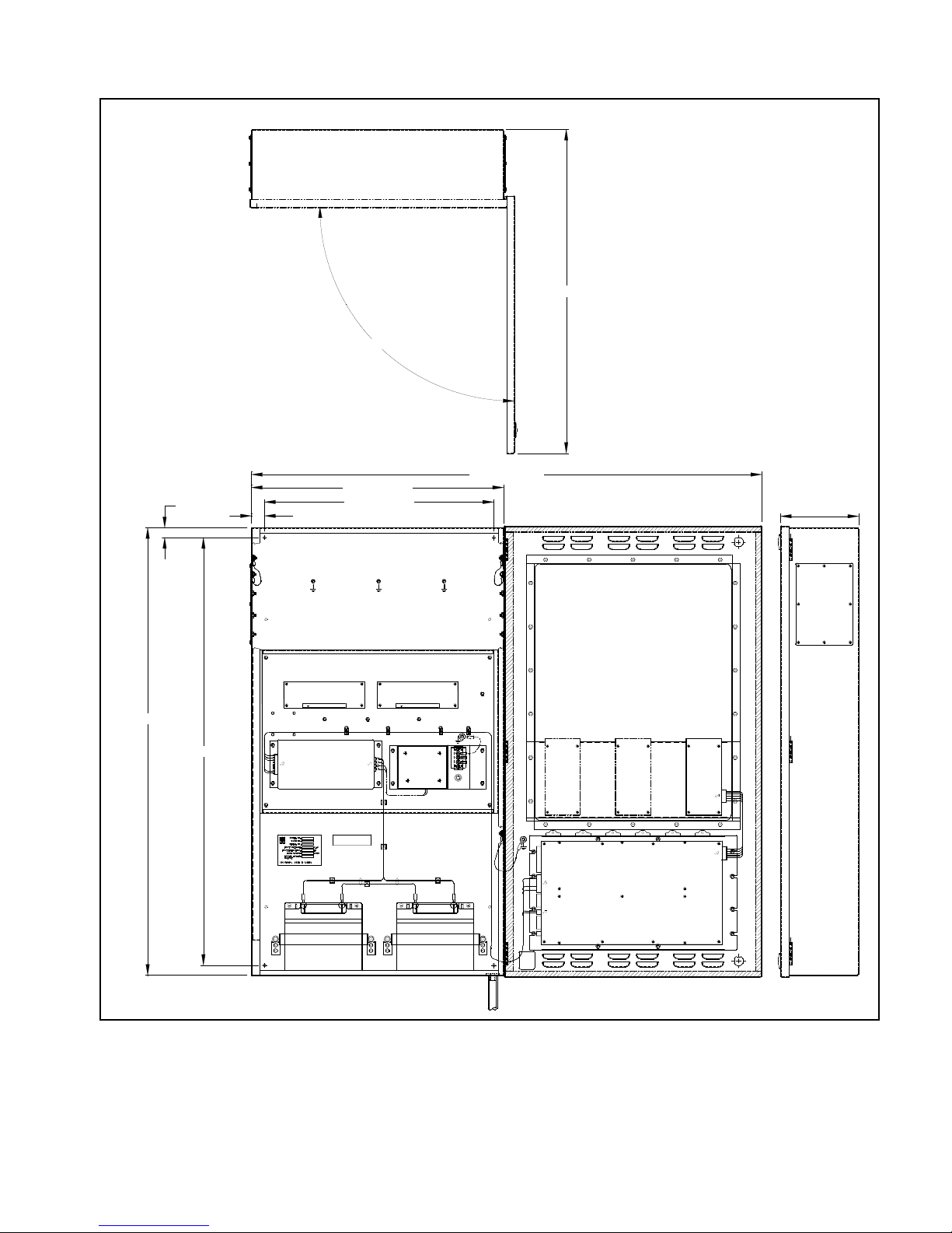
PRO-2000 X6S (standard)
The X6S is the standard panel housed in a 24" x 30" (610 mm x 762 mm) enclosure. The X6S consists of a
processing unit (MPU to process all field data and a display unit (LCD) to display all events. The LCD has a
standard 2 line x 40 character display with the associated display list controls and indicators and the standard 24
configurable indicators (LEDS) and 12 configurable push buttons.
PRO-2000 X6B (blank)
The X6B is the blank panel housed in a 24" x 30" (610 mm x 762 mm) enclosure. It has the same features as the
X6S, but without a display unit (LCD).
PRO-2000 X6E (expanded)
The X6E is the expanded version housed in a 24" x 30" (61 0 mm x 762 mm) enclosure. It has the same features as
the X6S plus an additional 48 configurable indicators (LEDs) and an additional 24 configurable push buttons.
PRO-2000 X6M (MIMIC)
The X6M is the mimic version housed in a 24" x 41" (610 mm x 1041 mm) enclosure. It has the same features as the X6S plus a
geographic mimic providing a graphical representation of th e protected area. The mimic contains up to 144 indicators (LEDs) to
provide visual feedback and 72 programmable push buttons.
Figure 9: Synoptic Sketch of the PR0-2000, X6 Series
14
Page 21
PRO-2000 Installation and Operation Manual
MPU CCA
LITHIUM
MPU BACKPLANE
JUMPER
BATTERY
PRO-2000 X6 Common Features
The X6 Series supports communica tion and networking functions. The X6 can operate as a stand-alone panel or
it can be networked in a master/slave configuration. The master can be configured to monitor and control the
slave panels as well as monitor its own devices.
The X6 panels can support communication to one RS-232 and one repeater network using small communication
modules. By adding an RS-232 communication module to the MPU card, the X6 panels can communicate with
external devices, such as printers or computers, via a standard modular pho ne j ack. The RS- 23 2 communicatio n
module supports one channel. The built-in RS-422 commun ication module enables X6 panels to support a
maximum of two Repeater networks. The RS-422 communication module supports 2 channels. For enhanced
networking capabilities, Communication interface cards can be added to the panel.
The printer used must be UL Listed (ULC Listed in Canada).
The X6 panels can accept up to 6 of the following expansion cards:
• Addressable Detector Interface (ADI) card - smoke/heat detectors, monitor modules, control modules, and 4
onboard supervised/unsupervised outputs
• 24/32 Zone Supervised Input (S1) card - conventional detectors, shorting and non-shorting devices
• 12 Zone Supervised OUTPUT (SO) card - supervised outputs and dry contacts
• Communication Card - networked configurations
General Installation Guidelines
The panel should be installed in a dry, clean, well lit and secured area. No combustible or hazardous material
should be stored in the vicinity of the installed unit. The installation must comply with all local and/or national
regulations and codes of practice governing fire alarm system installation, electrical wiring, life safety, etc.
Special Handling
Circuit cards are to be stored in anti-static packaging and kept away from the sun and from direct sources of
intense UV light. The circuit card may be subject to degradation due to electrostatic discharge; therefore
grounding straps must be worn when handling the cards.
Enabling the Onboard Lithium
Battery Backup
The X6 panels are shipped with the jumper for the
lithium battery disconnected. You must insert the
jumper to activate the battery backup for the real
time clock and the RAM memory used for the
event log. Jumper is located on the MPU (JP3).
Cable Entry and Internal
Routing
On the enclosure there are two removable cable
entry plates. These plates are to be removed,
punched, and re-installed. For additional entry
holes, outside the cable entry plates:
1. Disconnect the wiring harness from the
MPU to the LCD card.
2. Disconnect the door ground strap and
remove the enclosure door with
attached electronics from the enclosure
base.
3. Remove the mounting plate with the
attached electronics from the enclosure base.
Figure 10: Micro-processor (MPU)
15
Page 22

PRO-2000, X6 SERIES - S/B/E/M
Cable entry holes must be punched in accordance with the following criteria:
• Separate holes are required for the entry of Power-Limited and Non -Power-Limited circuit cables.
• Centre-to-centre spacing between an entry hole for Power-Limited circuit cables and an entry hole for NonPower-Limited circuit cables must not be less than two (2) times the diameter of the larger entry hole.
• Sufficient clearance must be provided around each hole to allow for any required cond uit fittings, cable-clamp s,
lock nuts, washers or other hardware.
• Exclusive entry holes must be provided for the Primary AC Supply cable and for the External Standby Supply
(battery backup) cable if required.
• At no point inside the enclosure must the spacing between power-limited and non-power-limited circuit
conductors be less than 6.4mm (¼ inch).
Wire lengths inside the enclosure should be kept to a minimum.
Cables must not interfere with, or touch any circuit card components other than the intended co nnector terminals.
Grounding and Bonding
All supply and device wiring must be grounded and bonded in accordance with applicable local regulations
governing the wiring of Fire Alarm Systems.
Enclosure Installation
All cable entry holes should be punched out prior to installation of enclosure base.
Ensure wall or structure to which the enclosure base is being mounted is capable of supporting a fully loaded unit.
Sufficient clearance must be provided around the unit to allow the enclosure door to be fully opened (180°) without
impediment. The enclosure box may be semi-flush mounted pro vided no less than 5 cm (2 inches) of th e box frame
protrudes from the wall surface.
The top of the enclosure should be no more than 2.0 meters (6.7 feet) above the finished floor.
Recommended mounting hardware: four ¼" pan head screws (If bolts are used, four suitable flat washers are
required).
1. Remove the ground strap (14 Gauge, green) between the enclosu re base an d door by loosening and removing the
ground stud nut and star washer.
2. Remove the MPU-LCD harness connector from J6 on the LCD card.
3. Remove the enclosure door from th e slip hin g es.
4. Remove the mounting plate, with attached electronics and power supply, fro m the enclosure base.
5. Secure the enclosure base to the wall using the four ¼” panhead screws.
6. Align the mounting plate, with attached electronics and power supply, to the enclosure base threaded studs and
secure with attaching nut and washer.
7. Re-install the door and ground strap between door and enclosure base.
8. Reconnect the MPU-LCD harness connector at J6 on the LCD card.
16
Page 23
PRO-2000 Installation and Operation Manual
7.16" [181.97mm]
90°
29.68" [753.92mm]
46.76" [1187.60mm]
23.10" [586.74mm]
1.20" [30.48mm] 21.00" [533.40mm]
0.90" [22.86mm]
28.20" [716.28mm]
30.00" [762.00mm]
Figure 11: X6S, Installation Layout
17
Page 24
PRO-2000, X6 SERIES - S/B/E/M
7.16" [181.97mm]
90°
29.68" [753.92mm]
46.76" [1187.60mm]
23.10" [586.74mm]
1.20" [30.48mm]
21.00" [533.40mm]
0.90" [22.86mm]
28.20" [716.28mm]
30.00" [762.00mm]
Figure 12: X6B, Installation Layout
18
Page 25
PRO-2000 Installation and Operation Manual
7.16" [181.97mm]
90°
29.68" [753.92mm]
46.76" [1187.60mm]
23.10" [586.74mm]
1.20" [30.48mm]
21.00" [533.40mm]
0.90" [22.86mm]
28.20" [716.28mm]
30.00" [762.00mm]
Figure 13: X6E, Installation Layout
19
Page 26
PRO-2000, X6 SERIES - S/B/E/M
7.16" [181.97mm]
90°
29.68" [753.92mm]
46.76" [1187.60mm]
23.10" [586.74mm]
1.20" [30.48mm]
21.00" [533.40mm]
41.00" [1041.40mm]
39.20" [995.68mm]
0.90" [22.86mm]
Figure 14: X6M, Installation Layout
20
Page 27

PRO-2000 Installation and Operation Manual
Hookup of AC Power and Batteries
The Power Supply provides a regulated 28 VDC to the PRO-2000 series and provides charge current to the optional
backup batteries. As the batteries are kept permanently charged, power is continuously provided (Uninterruptible Power
Supply or UPS). The power supply AC ratings are as follows:
120 VAC Version: V = 120 VAC nominal, 1 =1.5 A, Frequency 60Hz
220 VAC Version: V = 220 VAC nominal, 1 =0.8 A, Frequency 50Hz
LEDs are visible on the Power Supply indicating the functional status of the unit. As the Power Supply is convection
cooled, no fans or blowers are required. The transformer and power supply mount directly on the mounting plate.
A built-in battery charger maintains the batteries at full capa city. After extended power outages, the charger restores the
batteries to full capacity. Short circuit, over-voltage and brownout monitoring circuits protect all powered components by
switching to the batteries whenever a trouble condition exists in the power supply.
Alarm Supply
Power to the alarm devices in a system must be supplied from a separate battery backed-up Power Supply which is "UL
listed (ULC listed in Canada)” for fire protective signal system use.
AC Power Connection
CAUTION: Ensure all voltage sources are disconnected from the panels before installing or removing cards.
1. Remove terminal cover from terminal block, TB1, located on the transformer bracket.
2. Connect Primary supply Ground wire (green) to Ground stud.
3. Connect Primary supply Neutral wire (white) to TB1 NEUTRAL terminal.
4. Connect Primary supply Line wire (black) to TB1 LINE terminal.
5. Replace and secure terminal cover on TB1.
6. Maximum 150 V AC to Ground.
Installing Batteries in the Enclosure
The following instructions apply to stems requiring 42 Amp-Hours or less of battery back-up capacity.
1. Remove battery retaining hardwa re.
2. Place two new fully charged 12V batteries on the bottom of the enclosure. Use 12V sealed lead-acid batteries.
3. Connect jumper between the batteries ‘A’ (+) and ‘B' (-) poles (see Figure 15).
4. Connect black wire terminal to battery 'A'.
5. Connect red wire terminal to battery 'B' (+).
6. Replace battery and secure with retaining hardware.
For Calculation of Battery Requirements refer to Appendix A.
21
Page 28
PRO-2000, X6 SERIES - S/B/E/M
J
2
J
1
E
S
F
U
F
.
E
S
U
F
.
E
F
U
B
L
A
C
K
R
E
D
P
O
W
E
R
-
L
I
M
I
T
E
D
C
I
R
C
U
I
T
J
U
M
P
E
R
A
G
R
O
U
N
D
S
T
U
D
G
R
O
U
N
D
N
E
U
T
R
A
L
L
I
N
E
F
U
S
E
(
F
1
)
B
N
O
N
P
O
W
E
R
-
L
I
M
I
T
E
D
C
I
R
C
U
I
T
S
N
O
N
P
O
W
E
R
-
L
I
M
I
T
E
D
C
I
R
C
U
I
T
S
Figure 15: Battery Hookup
22
Page 29
PRO-2000 Installation and Operation Manual
Geographic MIMIC
(MIMIC driver)
LCD expander
Display unit
(LCD)
Transformer
115 or 220 VAC
Power Supply
and battery
charger
Batteries
X0M
X0E
X0S
Power-limited circuits
Non power-limited
circuit
To host panel
(RS-422)
AC power
RS-422
Module
Figure 16: Synoptic Sketch of the PRO-2000, X0 Series
PRO-2000 X0 Series - S/E/M
The PRO-2000 X0 Series are remote annunciator panels for the X2 and X6 Series.
The PRO-2000 X0 Series consist of three types of panels: the X0S, the X0E, and the X0M.
PRO-2000 X0S (Standard)
The X0S is the standard panel
housed in a 23" x 24" (584 mm x
610 mm) enclosure. The X0S
consists of a display unit which
repeats all events report ed by the
X2 or X6 host panel. It has the
standard 2 lines x 40 character
display with the associated
display list controls and indicators
and the standard 24 configurable
indicators(LEDs) and 12
configurable push buttons.
PRO-2000 X0E (Expanded)
The X0E is the expanded version
housed in a 24" x 30" (610 mm x
762 mm) enclosure. It has the
same features as the X0S plus an
additional 48 configurable
indicators (LEDs) and an
additional 24 configurable push
buttons.
PRO-2000 X0M (Mimic)
The X0M is the mimic version
housed in a 24" x 41" (610 mm x
1041 mm) enclosure. It has the
same features as the X0S plus a
geographic mimic providing a
graphical representation of the
protected area. The mimic
contains up to 144 indicators
(LEDs) to provide visual feedback
and 72 programmable push
buttons.
PRO-2000 X0, Common Features
The X0 panels operate as repeater panels. All the user interface functionality available on the host (X2 or X6) is
also available on the repeater panel. This includes all display lists (alarm, supervisory, trouble, etc.),
acknowledgement and reset functions, as well as System Maintenance accessibility.
The built-in RS-422 communication module allows the X0 Series to be connected to a host. Other than the RS422 communication module, there are no expansion cards available with this unit.
General Installation Guidelines
X0 panels should be installed in a dry, clean, well lit and secured area. No combustible or hazardous material
should be stored in the vicinity of the installed unit. The installation must comply with all local and/or national
regulations and codes of practice governing fire alarm system installation, electrical wiring, life safety, etc.
23
Page 30

PRO-2000 X0 Series - S/E/M
Special Handling
Circuit cards are to be stored in anti-static packaging and k ept away from the sun and from direct source s of intense
UV light. The circuit card may be subject to degradation due to electrostatic discharge; therefore grounding straps
must be worn when handling the cards.
Cable Entry and Internal Routing
On the enclosure there are two removable cable entry plates. These plates are to be removed, punched, and reinstalled. If additional entry holes are required outside the cable entry plates, before punching cable entry holes,
disconnect the door ground strap and remove the enclosure door with attached electronics.
Cable entry holes must be punched in accordance with the following criteria:
• Separate holes are required for the entry of Power-Limited and Non -Power-Limited circuit cables.
• Centre-to-centre spacing between an entry hole for Power-Limited circuit cables and an entry hole for NonPower-Limited circuit cables must not be less than two (2) times the diameter of the larger entry hole.
• Sufficient clearance must be provided around each hole to allow for any required cond uit fittings, cable-clamp s,
lock nuts, washers or other hardware.
• At no point inside the enclosure must the spacing between power-limited and non-power-limited circuit
conductors be less than 6,4mm (¼ po).
Wire lengths inside the enclosure should be kept to a minimum.
Cables must not interfere with, or touch any circuit card components other than the intended co nnector terminals.
Grounding and Bonding
All supply and device wiring must be grounded and bonded in accordance with applicable local regulations
governing the wiring of Fire Alarm Systems. The enclosure must be connected to earth Ground.
Enclosure Installation
All cable entry holes should be punched out prior to installation of base.
Ensure wall or structure to which the enclosure base is being mounted is capable of supporting a fully loaded unit.
Sufficient clearance must be provided around the unit to allow the enclosure cover door to be fully opened (180°)
without impediment. The enclosure box may be semi-flush mounted provided no less than 5 cm (2 inches) of the
box frame protrudes from the wall surface.
The top of the enclosure should be no more than 2 meters (6.7 feet) above the finished floor.
Recommended mounting hardware: four ¼ “ pan head screws (if bolts are used, four suitable flat washers are
required).
1. Remove the ground strap (14 Gauge, green) between the enclosu re base an d door by loosening and removing the
ground stud nut and star washer.
2. Remove the enclosure door from th e slip hin g es.
3. Secure the enclosure to wall using the four ¼” pan head screws.
4. Reinstall the door and ground strap between the door and the enclosure base.
24
Page 31

PRO-2000 Installation and Operation Manual
7.16" [181.97mm]
90°
29.68" [753.92mm]
46.76" [1187.60mm]
21.00" [533.40mm]
23.10" [586.74mm]
1.20" [30.48mm]
22.20" [563.88mm]
24.00" [609.60mm]
0.90" [22.86mm]
Figure 17: X0S, Installation Layout
25
Page 32

PRO-2000 X0 Series - S/E/M
29.68" [753.92mm]
46.76" [1187.60mm]
1.20" [30.48mm]
23.10" [586.74mm]
21.00" [533.40mm]
28.20" [716.28mm]
0.90" [22.86mm]
30.00" [762.00mm]
7.16" [181.97mm]
90°
Figure 18: X0E, Installation layout
26
Page 33

7.16" [181.97mm]
90°
29.68" [753.92mm]
46.76" [1187.60mm]
1.20" [30.48mm]
23.10" [586.74mm]
21.00" [533.40mm]
39.20" [995.68mm]
41.00" [1041.40mm]
0.90" [22.86mm]
PRO-2000 Installation and Operation Manual
Figure 19: X0M, Installation Layout
27
Page 34

PRO-2000 X0 Series - S/E/M
23.10" [586.74mm]
24.00" [609.60mm]
7.16" [181.94mm]
21.00" [533.40mm]
22.20" [563.88mm]
1.20" [30.48mm]
46.76" [1187.60mm]
90°
29.68" [753.92mm]
0.90" [22.86mm]
Figure 20: X0S, Installation Layout with Power Supply and Batteries
28
Page 35

PRO-2000 Installation and Operation Manual
7.16" [181.97mm]
21.00" [533.40mm]
1.20" [30.48mm]
23.10" [586.74mm]
46.76" [1187.60mm]
28.20" [716.28mm]
0.90" [22.86mm]
30.00" [762.00mm]
90.00°
29.68" [753.92mm]
Figure 21: X0E, Installation Layout with Power Supply and Batteries
29
Page 36

PRO-2000 X0 Series - S/E/M
7.16" [181.97mm]
90.00°
29.68" [753.92mm]
0.90" [22.86mm]
39.20" [995.68mm]
41.00" [1041.40mm]
1.20" [30.48mm]
23.10" [586.74mm]
46.76" [1187.60mm]
21.00" [533.40mm]
Figure 22: X0M Installation Layout with Power Supply and Batteries
30
Page 37

PRO-2000 Installation and Operation Manual
X2M
MASTER REPEATER
X0M
SLAVE #1
X2S
Addressable devices
stub/loop
Conventional notification or
initiating device stub
X6E
Conventional initiating
device stub
Conventional notification
device stub
SLAVE #2
PRINTER
PRO-2000
network
(stub or loop)
PRO-2000 Multi-Panel Systems
PRO-2000 panels can be programmed to act as Master or Slave panels. A Master panel monitors and controls a
system comprising several Slave panels.
Up to 32 PRO-2000 Slave panels can be con nected, in an ope n o r closed loo p config uration, to the ma ster panel
by means of a 4-conductor, full duplex, serial communication data link.
Should a communication fault occur, isolating one or more Slave panels from the Master panel, the isolated
panels revert to the stand-alone mode. In this mode, fire alarms are annunciated locally.
One or all of the networked panels can have a push button as a General Alarm. The General Alarm functiona lity is
configurable. Activating a General Alarm, either through devices or through the GA ON/OFF push button,
broadcasts the alarm to all the panels. Silencing the General Alarm at any panel silences all the 'General Alarm'
devices. Any new alarm, anywhere in the system, reactivates all the 'General Alarm' devices.
Figure 23: PRO-2000 Networked Panels
31
Page 38

PRO-2000 Multi-Panel Systems
LCD
TX1+
4
1
2
3
J6
X2 PANEL
5
6
TX1-
28V
GND
RX1+
RX1-
RX2-
RX2+
GND
28V
TX2-
TX2+
6
2
5
4
3
J8
1
GND
28V
6
J9
5
RX2-
RX2+
TX2-
TX2+
28V
GND
RX1-
LCD
X0 PANEL (REPEATER)
RX1+
GND
28V
TX1-
TX1+
6
2
5
4
3
J8
1
6
2
5
4
3
J6
1
TX1+
28V
TX1-
GND
RX1-
RX1+
X0 PANEL (REPEATER)
TX2+
28V
TX2-
GND
RX2+
RX2-6
5
4
J8
3
2
1
6
5
4
J6
2
3
1
LCD
Omit these wires
for stub operation
Note 2
Note 1
RX1- 6
X6 PANEL
28V
RX1+
GND
TX1+
TX1-
RX2-
RX2+
28V
GND
TX2-
MPU
TX2+
3
4
5
1
J2
2
6
5
2
4
3
1
J3
3
4
5
2
6
3
4
5
6
1
J8
RX1+
RX1-
GND
TX1+
TX1-
28V
RX2-
RX2+
GND
28V
2
X0 PANEL (REPEATER)
1
J6
TX2+
TX2-
LCD
Wires to be omitted
for stub operation
RX2- 6
RX2+
RX1-
RX1+
28V
GND
TX2-
TX2+
TX1-
28V
GND
3
4
5
J8
1
2
6
5
2
4
3
TX1+
LOCAL LCD
J6
1
Note 3
Note 2
Note 1
ALL CIRCUITS ARE POWER-LIMITTED AND SUPERVISED
ALL CIRCUITS ARE POWER-LIMITED AND SUPERVISED
X2 SERIES Max. 28 V supply cable length depends on configuration.
Must run in conduit separate from Tx and Rx cables.
Maximum current (short circuit: 4.5 Amp).
Maximum current (short circuit: 1 Amp).
X6 SERIES Max. 28 V supply cable length depends on configuration.
Must run in conduit separate from Tx and Rx cables.
NOTES
1.
Number of Repeaters limited by the configuration of the Host panel.
An external power supply can be used to extend the number of Repeaters.
Use only UL Listed for Fire Protective Signaling Systems (ULC Listed in Canada)
regulated, isolated 24VDC power supply (supervised and power limited).
3.
Use shielded, twisted pair cables, one pair for Tx lines, one pair for Rx lines.
No branches
or T-Taps allowed. Shields to be connected according to specific
system Wiring Diagrams.
Maximum cable length for communication: 1 Km between panels.
Maximum cable resistance (per pair): 40 Ohms.
Maximum loop current (short circuit): 150 mA.
Figure 24: X2 and X6 Network Wiring to a Repeater, X0
Minimum detected ground fault impedance is 10K ohms.
32
Page 39

LCD
TX1+
4
1
2
3
J6
X2 PANEL
5
6
TX128V
GND
RX1+
RX1-
RX2-
RX2+
GND
28V
TX2-
TX2+
6
2
5
4
3
J8
1
RX2+
COMM CARD
X6/X2 PANEL
RX2-
TX1+
TX1-
RX1+
RX1-
3
7
4
5
6
J1
8
TX1+
28V
TX1-
GND
RX1-
RX1+
X2 PANEL
TX2+
28V
TX2-
GND
RX2+
RX2-
6
5
4
J8
3
2
1
6
5
4
J6
2
3
1
LCD
Omit these wires
for stub operation
ALL CIRCUITS ARE POWER-LIMITED AND SUPERVISED
MASTER PANEL
SLAVE PANEL #1
SLAVE PANEL #2
2
1
TX2TX2+
USE SHIELDED TWISTED PAIR CABLE.
NO BRANCHES OR T-TAPS ALLOWED.
MAXIMUM DISTANCE BETWEEN CONTROL UNITS: 1 Km.
MAXIMUM CABLE RESISTANCE BETWEEN CONTROL UNITS: 40 Ohms.
MAXIMUM LOOP CURRENT (SHORT CIRCUIT): 150 mA.
MAXIMUM VOLTAGE: 7.0 VDC.
SHIELDS TO BE CONNECTED ACCORDING TO SPECIFIC SYSTEM
WIRING DIAGRAMS.
NOTES:
1.
2.
3.
4.
5.
6.
7. MINIMUM DETECTED GROUND FAULT IMPEDANCE IS 10K OHMS.
PRO-2000 Installation and Operation Manual
Figure 25: Networking The X2 and X6 Using The Communication Card
33
Page 40

MAIN PROCESSING CARDS
MAIN PROCESSING CARDS
There are two main processing cards, the MPU and the LCD. These cards form the basis for the PRO-2000 Pane ls'
electronics.
In the X6 panels, the MPU card with the MPU Backplane, expansion cards (optional), Power Supply and
Transformer are mounted to a removable mounting plate in the enclosure base. The LCD card is mounted directly
on the enclosure door.
In the X2 Series the power supply and transformer are mounted to a removable mounting plate in the enclosure
base. The LCD with the LCD Backplane and optional expansion cards are mounted on the enclosure door.
MPU - Main Processing Unit card
The Main Processing Unit (MPU) provides
processing and communication circuitry for the
X6 series panels. It provides two RS-422 fullduplex, 4-conductor serial links used for
communications with the local LCD panel.
The MPU is shipped pre-installed on the
enclosure backplate with an MPU Backplane
attached and an, RS-422 communication module
installed. The MPU Backplane enables the MPU
to have up to 6 expansion cards installed, for
example, the ADI, Supervised output, or
Supervised Input cards. The MPU Backplane has
a side connector to plug into the MPU expansion
slot providing connectivity between the MPU and
the expansion cards.
The MPU provides monitoring of the power
supply for AC/DC fault detection. The card
provides the following visual indicators and
controls:
• Various status LEDs provide a visual indication of the card's health. There are Red LEDs for error codes,
blinking LEDs (Running) indicating the board is working; Green Power LEDs, and Communication LEDs.
• Reset push button to hard reset the MPU card.
• DIP switch providing software options. Factory set only.
• Rotary switch allowing the selection of different configuration modes. Factory set only.
• Three jumpers, two for the watchdog and one for battery. These jumpers must be connected at all times. A
watchdog circuit, monitoring microprocessor, halts system operation if a hardware or sof tware failure occurs.
The lithium battery provides the backup for the real-time clock and the RAM memory used for event logging.
The real-time clock provides time and date for event recording.
Figure 26: MPU (Main Processing Unit) Card
34
Page 41

PRO-2000 Installation and Operation Manual
RS-422
J3
RS-232
Phone Jack
LCD Display
RS-422 LinkRS-422 Link
LCD Display
J2
RS-232
JP1
JP3
Jumpers
Rotary Switch
DIP Switches
Reset Button
Reset
Status
Error code
Indicators
Communication
Indicators
Power/Status
Indicators
Monitor Power
AC/DC Fault
Power
Connector
Running
J10
J8
LD25
LD20
LD12
LD19
LD11
LD1
SW3
SW1
SW2
1
J1
Master Alarm
and Trouble
Relays
Lithium
Battery
RAM
Program Device
Configuration
Communication
module sockets
Position for Expansion
cards with screw
termination to field devices
Connectors for MPU Backplane
JP4
Figure 27: MPU Backplane Connectors
35
Page 42

MAIN PROCESSING CARDS
When a system is first delivered the MPU card has its internal battery jumper, JP3, disabled. Prior to installation,
move the jumper shunt (located above the board mounted battery) into position over both pins. If the jumper is
missing, the panel will annunciate a "Clock Battery Fault “ at power up. If the jumper is in, you can remove power
and the event log and the clock remain powered.
The MPU has two sockets for adding communication modules. Depending on your configuration, these could be
either the RS-232 or RS-422 communication modules. Installing an RS-232 module activates the phone jack
allowing MPU software configuration through an external PC or communication with a printer (depending on
position of SW1, see Table 4 below).
Installing an RS-422 module activates the two connectors to the LCD. The two connectors provide power to the
LCD. This available power is current limited to 1 amp. Note-the MPU ships with a pre-installed RS-422 module.
The MPU has built-in Common Alarm and Fault Relay-2 For m-C contact s for each relay. The Common Alarm Relay
activates whenever an alarm is present on the system. The Common Fault Relay activates whenever a fault is
present on the system. The rating for Common Alarm and Fault Relay is 2A at 30VDC.
COMM Loop (S1 (J2) X) COMM Loop (S2 (J3) Y)
Signal Pin Signal Pin Signal Pin
TX1+ (out) 1 TX2+ (out) 1 TX (out) 5
TX1- (out) 2 TX2- (out) 2 RX (in) 2
24V 3 24V 3 RTS* (out) 3
GND4GND4CTS* (out)6
RX1+ (in) 5 RX2+ (in) 5 CD* (in) 1
RX1- (in) 6 RX2- (in) 6 GND 4
Table 2: MPU Pinouts
RS-232 Modular Phone
Jack (J4)
Common Alarm and
Trouble Relays (J1)
2A max @ 30V DC
Pin
Resistive
C1 1
NC1 2
Trouble
Alarm
Table 3: MPU Relays
NO1 3
C2 4
NC2 5
NO2 6
C1 7
NC1 8
NO1 9
C2 10
NC2 11
NO2 12
SW1
SW2 Normal position: All OFF
SW3 Used to reset the MPU card
36
0: Printer, 1: Configuration, 2: Normal/Diagnose; 3: ModBus,
4: LCD, 5: Network, 6: Redundant, E: Firmware upgrade,
F: Default configuration
Table 4: MPU Switches
Page 43

PRO-2000 Installation and Operation Manual
Jumper Function Position
JP2 Watchdog Enable Installed
JP1 Watchdog one-shot mode Installed
JP3 Lithium Battery Enable Installed on site
JP4 RAM Size Selection
Non installed when 128K x 8 RAM chips are used.
Installed when 512K X 8 RAM chips are used.
Table 5: MPU Jumpers
LED Function Definition
ON when the MPU is in a hardware reset state
LD1 (red) Reset indicator
LD2 (green) Status indicator Not used (reserved)
LD3 (green) Running indicator Blinks when the MPU is executing its normal program
LD4-LD11 (red) Error code indicators Used to report internal error conditions
LD12-LD19
Communication indicators for the
on board data links
LD20 (green) 24 V input indicator ON when the 24V input connector J10 is powered.
LD21 green) VCC indicator ON when the local VCC (5V) regulator is functional
LD22 green) VISO1 indicator
LD23 (green) VISO2 indicator
LD24 (green) LCD loop power, X side ON when power is available on the LCD connector, X side, J2
LD25 (green) LCD loop power, Y side ON when power is available on the LCD connector, Y side, J3
- At power up, or
- On a fatal hardware or software failure
These indicators will blink when data is received or transmitted
on one of the data links.
LD12 (RX1) and LD13 (TX1) for RS-422, X side (local LCD)
LD14 (RX2) and LD15 (TX2) for RS-422, Y side
LD16 (RX3) and LD17 (TX3) for RS-232
LD18 (RX4) and LD19 (TX4): are reserved
ON when the local isolated power supply #1 is functional (RS422 power supply)
ON when the local isolated power supply #2 is functional (RS232 power supply)
Table 6: MPU LEDs
37
Page 44

MAIN PROCESSING CARDS
RS-422
RS-232
Phone Jack
RS-232
Rotary Switch
DIP Switch
Reset
pushbutton
Error code
Indicators
Communication
Indicators
J2
Master Alarm
and Trouble
Relays
Communication
module socket
Mimic or
LCD Expansion
LD27
LD28
LD39
LD34
Running & Status
LD40
LD50
LD58
LD51
Indicators
Connector
Lithium Battery
Jumper
REAR VIEW
SW3
JP4JP6
J4
J5
J6
J8
J9
J7
Monitor Power
AC/DC fault
X side
RS-422
X side
Power Input
Y side
RS-422
Y side
Power Input
Metalized ground
External Buzzer
Connection
J17
J11 J10
Escutcheon
Connection
J12
Access Control Key
Connection
J2 J3
LCD Expansion
Backplane
SW1
SW2
1
LD1 LD2
Connection
LCD - Liquid Crystal Display card
The LCD implements the user interface to the PRO-2000 panels using LEDs and a 2-line x 40-character LCD unit.
38
Figure 29: LCD Backplane Connectors
Figure 28: LCD Card
Page 45

PRO-2000 Installation and Operation Manual
X6 and X0 series
The LCD performs only display functions.
X2 Series
• The LCD performs processing and display functions.
• The LCD Backplane is used to provide connectivity between the LCD and the interface cards. Up to 2
expansion cards can be connected to the LCD Backplane.
• The LCD has built-in Master Alarm and Fault Relay-2 Form-C contacts for each r elay. The Master Alarm
Relay is activated whenever an alarm is present on the system. The Master Fault Relay activates whenever a
fault is present on the system.
• The LCD monitors the power supply for AC/DC fault detection.
• Various status LEDs provide a visual indication of the card's health. There are Red LEDs for error codes,
blinking LEDs (Running) indicating the board is working, Green Power LEDs, and Communication LEDs.
• Reset push button to hard reset the LCD card.
• Dipswitch providing software options. Factory set only.
• Rotary switch allowing the selection of different configuration modes. Factory set only.
• Three jumpers, two for the watchdog and one for lithium battery. These jumpers must be connected at all
times. A watchdog circuit, monitoring the microprocessor, halts system operation if a hardware or software
failure occurs. The lithium battery provides the backup for the real- time clock and the RAM memory used for
event logging. The real-time clock provide s ti me an d date for event recording.
When a system is first delivered the LCD card has its internal battery jumper, JP6, disabled. Prior to installation
move the jumper shunt into position over both pins. If the jumper is missing the panel will annunciate a "Clock
Battery Fault" at power up. If the jumper is in, you can remove power and the event log and the clock remain
powered.
Up to two (2) expansion cards can be added via the LCD backplane. For panel models X0E, X0M, X2E, X2M,
X6E, and X6M, the LCD Connector J2 connects the LCD to the MIMIC Driver card or the LCD Expander card for
additional display/control capabilities.
The LCD has two sockets for adding communication modules. Depending on your configuration, these could be
either RS-232 or RS-422 communication modules.
For LCDs used as processing and display units, installing an RS-232 module activates the phone jack allowing
LCD software configuration through an e xternal PC, or interfacing to a Printe r (depending on position of SW1, see
Table 9). Installing an RS-422 module activates data links to other panels.
The RS-232 module is not used when LCDs are display units. Installing an RS-422 module activates data links to
the MPU or to a Repeater network.
39
Page 46

MAIN PROCESSING CARDS
LCD BACKPLANE
EXPANSION CARD
LCD
Figure 30: Expansion Card and LCD Backplane
40
Page 47

PRO-2000 Installation and Operation Manual
COMM Loop (S1 (J6) X) COMM Loop (S2 (J8) Y)
Signal Pin Signal Pin Signal Pin
TX1+ (out) 1 TX2+ (out) 1 TX (out) 5
TX1- (out) 2 TX2- (out) 2 RX (in) 2
24V 3 24V 3 RTS* (out) 3
GND4GND4CTS* (in)6
RX1+ (in) 5 RX2+ (in) 5 CD* (in) 1
RX1- (in) 6 RX2- (in) 6 GND 4
Table 7: LCD Pinouts
Common Alarm and Trouble Relays (J4)
2A max@30V DC Resistive
C1 1
NC1 2
Trouble
Alarm
Table 8: LCD Relays
NO1 3
C2 4
NC2 5
NO2 6
C1 7
NC1 8
NO1 9
C2 10
NC2 11
NO2 12
RS-232 Modular Phone Jack
(J19)
Pin
Switch Position and description
For X2- 0: Printer, 1: configuration, 2: Normal/Diagnose; 3: ModBus, 4: LCD, 5: Network,
SW1
SW3 Used to reset LCD card
SW2 4 (MSB), 3, 2, 1 (LSB)
SW2 5
SW2 6 RS-422 Baud Rate - ON= see SW1, OFF = 19200.
SW2 7 (MSB) and 8 (LSB)
6: Redundant, E: Firmware, F: Default Config
For X0-: with SW2 bit 6 ON, RS422 Baudrate selection: 4: 2400, 5: 4800, 6: 9600,
7: 19200, 9: 64000.
Address ID of the LCD.
When OFF (Address ID = 0), X2 mode is selected.
Otherwise (Address ID 1-15), X0 mode is selected.
X0, with power supply.
ON returns hardware trouble to master.
Indicates the number of LCD Expander or Mimic
Driver module connected to the LCD.
Table 9: LCD Switches
41
Page 48

MAIN PROCESSING CARDS
Jumper Function Position
JP5 Watchdog enable Installed
JP4 Watchdog one-shot mode Installed
JP6 Lithium Battery enable Installed on site
JP2, JP3 RAM size function
LED Function Definition
LD39 (green) Status indicator Reserved
LD34 (green) Running indicator Blinks when the LCD is executing its normal program
LD40 - LD42
LD46 - LD50 (red)
LD51 - LD58 (green)
LD28 (green) 24V input indicator ON when the 24V input connectors J6, J7, J8, or J9 are powered
LD1 (green) VISO1 indicator ON when the local isolated power supply #1 is functional (RS-422)
LD2 (green) VISO2 indicator ON when the local isolated power supply #2 is functional (RS-232)
LD27 (green) Mimic Power indicator ON when power is available on the mimic connector, J2
- Non installed when 128 K x 8 RAM chips are used.
- Installed when 512 K x 8 RAM chips are used.
Table 10: LCD Jumpers
Error code indicators Used to report internal error conditions
These indicator will blink when data is received or transmitted on one
of the data links.
Communication indicators for
the on-board data links
LD51 (RX1) and LD52 (TX1) for RS-422, S1 (X) side
LD53 (RX2) and LD54 (TX2) for RS-422, S2 (Y) side
LD55 (RX3) and LD56 (TX3) for RS-232
LD57 (RX4) and LD58 (TX4) Reserved
Table 11: LCD LEDs
42
Page 49

PRO-2000 Installation and Operation Manual
EXPANSION CARDS
All expansion cards installe d in the PRO- 2000 Ser ies p ane ls are equip ped with st atus indicators (LEDs) mou nted
on the card to indicate each card's operating state. Only a skilled technician should proceed with card
replacement.
Expansion Card Installation
CAUTION: Ensure all voltage sources are disconnected fr om the Cont rol Unit befor e installing or remo ving cards. Wear
grounding strap when handling or wo rking with cards.
There are several types of expansion cards that can be added to the PRO-2000 Series panels. These are:
• Addressable Detector Interface (ADI) card - smoke/heat detectors, monitor modules, control modules, and 4
onboard supervised/unsupervised outputs
• 24/32 Zone Supervised Input (S1) card - conventional detectors, shorting and non-shorting devices
• 12 Zone Supervised OUTPUT (SO) card - supervised outputs and dry contacts
• Communication Card - networked configurations
When ordering expansion cards they come with an installation kit. Each kit has five plastic standoffs and one
metal standoff. The following steps can be used for the installation of any of the expansion cards.
1. Before placing the Expansion card onto the backplanes, attach all spacers to the Expansion card.
Each expansion card has a metal ring in the top right-hand side used for Ground fault monitoring and transient protection.
This is the place for the metal standoff.
2. Supporting the backplane with your hand, press the Expansion card on the appropriate expansion slot.
3. Secure the Expansion card to the MPU/LCD using the screws that come with the installation kit.
Refer to System Configuration Expansion card slot positions.
43
Page 50

MAIN PROCESSING CARDS
J1
Metalized
LD9 LD12
Power Indicators
Connector to
MPU or LCD
Field Wiring
RS-422
Field Wiring
J2
RS-232
LD1 LD8
RS-422 or RS-232 Sockets
Ground
Communication Card
Figure 31: Communication Card Connections
The Communication card enables the PRO-2000 p anels to be connected to var ious co mmunication interfaces such
as RS-232, and RS-422. You must install an RS-232 or RS-422 communication module (or both) into the interface
sockets of the Communication card. It is the installation of the communication modules that defines if the card i s
RS-422 and/or RS-232. Field wiring connections on the Communication card are dependent on the installed
module. The RS-422 communication module activates two serial data links on J1. The RS-232 communication
module activates one serial data link on J2.
The communication modules can be inserted in any socket, however, there cannot be two of the same
communication module on each Communication card.
The communication modules are powered through the Communication card. Each communication module uses an
isolated power supply and are fully isolated from the main system and from themselves. There is transient
protection provided on each module and Ground fault detection is separate for each communication module.
RS-422 Signal Name RS-232 Signal Name
J1-1 TX2+ (out) J2-1 TX (out)
J1-2 TX2- (out) J2-2 RX (in)
J1-3 RX2+ (in) J2-3 RTS* (out)
J1-4 RX2- (in) J2-4 CTS* (in)
J1-5 TX1+ (out) J2-5 BRG_out (out)
J1-6 TX1- (out) J2-6 CD* (in)
J1-7 RX1+ (in) J2-7 Not used
J1-8 RX1- (in) J2-8 GND
Table 12: Communication card Pin outs
LED Function Definition
These indicators will blink when data is received or transmitted on one of the
data links.
LD1-LD8 (green)
Communication indicators for
the on-board data links
LD9 (green) 24V input indicator ON when the 24V power from the Host system is present
LD10 (green) VCC Indicator ON when the local VCC (5 V) regulator is functional
LD11 (green) VISO1 Indicator ON when the local isolated power supply #1 is functional (RS-422, S1)
LD12 (green) VISO2 Indicator ON when the local isolated power supply #2 is functional (RS-232, S3)
LD1 (RX1) and LD2 (TX1) for RS-422, S1 (X) side
LD3 (RX2) and LD4 (TX2) for RS-422, S2 (Y) side
LD5 (RX3) and LD6 (TX3) for RS-232
LD7 (RX4) and LD8 (TX4) reserved
Table 13: Communication Card LEDs
44
Page 51

PRO-2000 Installation and Operation Manual
RX2+
COMM. CARD
RX2-
TX1+
TX1-
RX1+
RX1-
374
5
6
J1
8
ALL CIRCUITS ARE POWER-LIMITED AND SUPERVISED
SLAVE PANEL #1
2
1
TX2-
TX2+
USE SHIELDED TWISTED PAIR CABLE.
NO BRANCHES OR T-TAPS ALLOWED.
MAXIMUM DISTANCE BETWEEN CONTROL UNITS: 1 Km.
MAXIMUM CABLE RESISTANCE BETWEEN CONTROL UNITS: 40 Ohms.
MAXIMUM LOOP CURRENT (SHORT CIRCUIT):
150 mA., MAXIMUM VOLTAGE: 7.0 VDC.
SHIELDS TO BE CONNECTED ACCORDING TO SPECIFIC SYSTEM
WIRING DIAGRAMS.
NOTES:
1.
2.
3.
4.
5.
6.
MASTER PANNEL
COMM. CARD
J1
RX2-
TX1-
TX1+
RX1+
RX1-
6
7
8
5
4
RX2+
TX2-
TX2+
2
3
1
SLAVE PANEL #2
J1
TX1+
RX2+
RX2-
TX2-
TX2+
3
2
1
4
5
TX1-
RX1+
RX1-
768
COMM. CARD
TO RX1, TX1
ON SLAVE PANEL #3 - COMM. CARD
FROM RX2, TX2
ON LAST SLAVE PANEL - COMM. CARD
(OMIT THIS LINK FOR STUB OPERATION)
POWER-LIMITED CIRCUITS
7. MINIMUM DETECTED GROUND FAULT IMPEDANCE IS 10K OHMS.
Figure 32: Communication Card Wiring - Loop/Stub Mode
45
Page 52

MAIN PROCESSING CARDS
14”
14.5”
12.5”
16”
Four holes in backbox
for mounting.
Figure 33: APS-14127-00 Auxiliary Power Supply
APS-14127-00 Auxiliary Power Supply
The APS-14127-00 auxiliary power supply provides two power limited outputs, each rated at 28VDC and 2A. Both outputs can be used simultaneously and the to t al current available from th e power supp ly is 2.5A in st andby condition and
4A in alarm. In the event the main AC fails, the auxiliary supply battery will be connected without delay on the output
ensuring an uninterrupted supply to external circuitry. Output voltage is regulated at 28VDC during AC power condition
and will follow battery voltage (27 to 20VDC) during battery back-up periods. The battery will be disconnected at a voltage of 19.5V or less in order to prevent battery damage due to over-discharging.
The power supply has provision to charge batteries with 10 to 42 AH capacities. Normally open dry contact outputs are
provided to signal AC fail, DC fail or ground faults condition.
The two power-limited outputs are not supervised at the auxiliary power supply: The applications shown elsewhere in
this document will provide supply line supervision when wired as recommended.
APS-14127-00 Auxiliary Power Supply Enclosure Installation
Sufficient clearance must be provided around the unit to allow the enclosure door to be fully opened (180°) without
impediment. The enclosure box may be semi-flush mounted pro vided no less than 5 cm (2 inches) of th e box frame
protrudes from the wall surface.
The top of the enclosure should be no more than 2.0 meters (6.7 feet) above the finished floor. Recommended
mounting hardware: four ¼" pan head screws (If bolts are used, four suitable flat washers are required).
1. Remove the enclosure door from th e slip hin g es.
2. Secure the enclosure to wall using the four ¼” pan head screws.
3. Reinstall the door and the enclosure base.
46
Page 53

PRO-2000 Installation and Operation Manual
Figure 34: APS-14127-00 Auxiliary Power Supply Connector
Typical connection for APS-14127-00 auxiliary power supply is shown in next figure. In this scheme, s single monitor
module is used for picking up trouble information from the auxiliary supply. If individual trouble reporting is required,
use a single monitor module per trouble contact.
See sections on ADI and SO cards for further details for power connections.
Figure 35: APS-14127-00 Auxiliary Power Supply Typical
47
Page 54

MAIN PROCESSING CARDS
Trouble tracing information is provided by the 14043 control interface situated in upper left corner of the APS-14127-00
auxiliary power supply enclosure.
Figure 36: APS-14127-00 Auxiliary Power Supply LED Indicators
48
Page 55

12 Zone Supervised OUTPUT Card
J4
Metalized
Ground
Power Indicators
Connector to
MPU or LCD
Power Supply
External
LD1 LD5
J2 J3
11
Screw Connectors for Field Connections
Output Status
Indicator
LD6
LD17
JP25
LD6
JP25
Metalized
Ground
LD17
Power Indicators
LD1 LD5
External
Power Supply
J4
J5
SUBD Connector
for
Field Connections
Relays
Relays
Supervised
Jumper
Power
Jumper
Connector to
MPU or LCD
Indicator
Output Status
Figure 37: 12 Zone Supervised Output Card
PRO-2000 Installation and Operation Manual
The SO card supports 12 supervised outputs or 12 dry contacts (Form C). The card's 12 relays have jumpers to
determine if the outputs are supervised or not.
There are two versions of this card. It can either come with screw terminal connections or a DSUB connecto r . The
screw terminal connections allow more current load and should be used for high power outputs. The DSUB
connector version is limited in current handling but is easier to use when wiring a large number of outputs.
Supervision circuits use an external power supply (24V) isolated from the main power supply of the card. The
power supply should be regulated and UL Listed for Fire Protective Signaling Systems (ULC Listed in Canada),
battery backed-up, and fully supervised. The metallized Ground on the card provides the path to chassis for
transient protection.
To use dry contacts, no external power is required. The supervised jumper and power jumpe r should be removed.
To activate supervision circuits of the Supervised OUTPUT card, an external power supply must be connected to
the External Power Connector. T o configure each individua l OUTPUT as supervised, insert the supervised jumper
and remove the power jumper for that output.
Signal Connection Signal Connection Signal Connection Signal Connection
SO1-NO J2-1 SO4-NO J2-13 SO7-NO J3-1 SO10-NO J3-13
SO1-NC J2-2 SO4-NC J2-14 SO7-NC J3-2 SO10-NC J3-14
SO1-COM J2-3 SO4-COM J2-15 SO7-COM J3-3 SO10-COM J3-15
GND J2-4 GND J2-16 GND J3-4 GND J3-16
SO2-NO J2-5 SO5-NO J2-17 SO8-NO J3-5 SO11-NO J3-17
SO2-NC J2-6 SO5-NC J2-18 SO8-NC J3-6 SO11-NC J3-18
SO2-COM J2-7 SO5-COM J2-19 SO8-COM J3-7 SO11-COM J3-19
GND J2-8 GND J2-20 GND J3-8 GND J3-20
SO3-NO J2-9 SO6-NO J2-21 SO9-NO J3-9 SO12-NO J3-21
SO3-NC J2-10 SO6-NC J2-22 SO9-NC J3-10 SO12-NC J3-22
SO3-COM J2-11 SO6-COM J2-23 SO9-COM J3-11 SO12-COM J3-23
GND J2-12 GND J2-24 GND J3-12 GND J3-23
Table 14: 12 Zone Supervised OUTPUT Card Pin outs - Screw Termination
49
Page 56

MAIN PROCESSING CARDS
Signal Connection Signal Connection Signal Connection Signal Connection
SO1-NO J5-1 SO4-NO J5-13 SO7-NO J5-25 SO10-NO J5-37
SO1-NC J5-2 SO4-NC J5-14 SO7-NC J5-26 SO10-NC J5-38
SO1-COM J5-3 SO4-COM J5-15 SO7-COM J5-27 SO10-COM J5-39
GND J5-4 GND J5-16 GND J5-28 GND J5-40
SO2-NO J5-5 SO5-NO J5-17 SO8-NO J5-29 SO11-NO J5-41
SO2-NC J5-6 SO5-NC J5-18 SO8-NC J5-30 SO11-NC J5-42
SO2-COM J5-7 SO5-COM J5-19 SO8-COM J5-31 SO11-COM J5-43
GND J5-8 GND J5-20 GND J5-32 GND J5-44
SO3-NO J5-9 SO6-NO J5-21 SO9-NO J5-33 SO12-NO J5-45
SO3-NC J5-10 SO6-NC J5-22 SO9-NC J5-34 SO12-NC J5-46
SO3-COM J5-11 SO6-COM J5-23 SO9-COM J5-35 SO12-COM J5-47
GND J5-12 GND J5-24 GND J5-36 GND J5-48
Table 15: 12 Zone Supervised OUTPUT Card Pin outs - DSUB Termination
Signal Connection
VIN+ J4-1
VIN- J4-2
Vout+ J4-3, J5-49, J5-50
Vout- J4-4
Table 16: External Power Supply Connections
Jumper Function Position
JP2
JP4, 6, 8, 12, 14, 16, 18,
20, 22, 24
JP3, 5, 7, 9, 11, 13, 15,
17, 19, 21, 23, 25
Supervision mode for OUTPUT
#1
Supervision mode for outputs 2,
3, 4, 5, 6, 7, 8, 9, 10, 11, 12
Reserved Not installed
Table 17: 12 Zone Supervised OUTPUT Card Jumpers
Installed for la supervision (Use EOL
jumper for UL release device. Refer to
Release Service Devices section). Not
installed for dry contact.
LED Function Position
LD3 (green) 24V input indicator ON when the 24V power from the Host system is present.
LD2 (green) Fused 24V input indicator ON when the fused 24V from the Host system is present.
LD1 (green) VCC indicator ON when the local VCC (5V) regulator is functional.
LD5 (green)
LD4 (green)
External power input
indicator
External power OUTPUT
indicator
LD6-17 (green) outputs #1 through #12 State ON when corresponding OUTPUT is activated.
Table 18: 12 Zone Supervised OUTPUT Card LEDs
ON when a 24V power supply is connected to the external
power input (J4-1, J4-2)
ON when 24V power is available on the external power
connector (J4-3, J4-4). Indicates that the power is
available for the supervision circuits.
50
Page 57

PRO-2000 Installation and Operation Manual
EOL
24VDC
POWER
SUPPLY
(+) (-)
POWER LIMITED, SUPERVISED CIRCUITS
Jumper to be installed as per
supervision jumper Table 22.
See Appendix B for compatible NAC
or releasing devices.
1.
3.
NOTES:
(+)
(-)
SO CARD
2
1
1
4
2
J2
Note 3
J4
VIN+
VIN-
Note 4
2.
Max. allowable circuit voltage: 28 VDC
Max. current load (per relay circuit): 2A
4.
3
GND
C
NC
NO
ALL CIRCUITS ARE POWER-LIMITED
AND SUPERVISED
(NOTE 2)
Use only UL listed for Fire Protective Signaling Systems (ULC Listed in Canada) regulated, isolated
24VDC power supply (supervised and power-limited).
Use MP-300SP when NAC circuit
EOL devices must be on a mounting
plate. Use MP-320SP when solenoid
circuit EOL devices must be on a
mounting plate.
5. Minimum detected ground fault impedance is 10K ohms.
NOTE
:
1. MORE THAN ONE RELAY, VALVE OR SOLENOID PER OUTPUT IS NOT ALLOWED.
Figure 38: Supervised Output Wiring
51
Page 58

MAIN PROCESSING CARDS
Metalized ground
Power indicators
Connector to
MPU or LCD
LD1 LD5
J2 J3
11
Screw connectors for field connections
1+ 12- 24-13+
Supervised inputs 1 to 12 Supervised inputs 13 to 24
24 inputs
32 inputs
LD5LD1
Power indicators
Metalized ground
J4
AC
AC
12
J1
32
32
+-
Flat ribbon cable
64 pin connection
31
30
29
1
2
3
4
5
terminals
from field
devices
Connector to
MPU or LCD
Screw
24/32 Zone Supervised Input Card
Figure 39: 24/32 Zone Supervised Input Card
The Supervised Input card supports u p to 32 conventional detection zones. There are two versions of this card. One
is with screw termination and supports 24 supervised inputs.The other is used with model PCA-14308-00 screw
terminal adapter and gives access to 32 supervised inputs.
The supported field devices can be shorting or non-shorting devices. The Powe r indicators provide status of internal
voltages on the card. The metallic-mounting hole provides transient protection and Ground fault detection.
See Appendix B for the List of Conventional Devices which are compatible with 24/32 Zone Supervised Input card.
Signal Connection Signal Connection Signal Connection
SI1+ J2-1 SI9+ J2-17 SI17+ J3-9
SI1- J2-2 SI9- J2-18 SI17- J3-10
SI2+ J2-3 SI10+ J2-19 SI18+ J3-11
SI2- J2-4 SI10- J2-20 SI18- J3-12
SI3+ J2-5 SI11+ J2-21 SI19+ J3-13
SI3- J2-6 SI11- J2-22 SI19- J3-14
SI4+ J2-7 SI12+ J2-23 SI20+ J3-15
SI4- J2-8 SI12- J2-24 SI20- J3-16
SI5+ J2-9 SI13+ J3-1 SI21+ J3-17
SI5- J2-10 SI13- J3-2 SI21- J3-18
52
SI6+ J2-11 SI14+ J3-3 SI22+ J3-19
SI6- J2-12 SI14- J3-4 SI22- J3-20
SI7+ J2-13 SI15+ J3-5 SI23+ J3-21
SI7- J2-14 SI15- J3-6 SI23- J3-22
SI8+ J2-15 SI16+ J3-7 SI24+ J3-23
SI8- J2-16 SI16- J3-8 SI24- J3-24
Table 19: 24 Zone Supervised Input Card Pin outs
Page 59

PRO-2000 Installation and Operation Manual
The adapter's supervised input # is indicated near the screw connections. The + and - signs on the adapter
indicate the polarity of the connection.
Signal Connection Signal Connection Signal Connection Signal Connection
SI1+ J4-A32 SI9+ J4-A24 SI17+ J4-A16 SI25+ J4-A8
SI1- J4-C32 SI9- J4-C24 SI17- J4-C16 SI25- J4-C8
SI2+ J4-A31 SI10+ J4-A23 SI18+ J4-A15 SI26+ J4-A7
SI2- J4-C31 SI10- J4-C23 SI18- J4-C15 SI26- J4-C7
SI3+ J4-A30 SI11+ J4-A22 SI19+ J4-A14 SI27+ J4-A6
SI3- J4-C30 SI11- J4-C22 SI19- J4-C14 SI27- J4-C6
SI4+ J4-A29 SI12+ J4-A21 SI20+ J4-A13 SI28+ J4-A5
SI4- J4-C29 SI12- J4-C21 SI20- J4-C13 SI28- J4-C5
SI5+ J4-A28 SI13+ J4-A20 SI21+ J4-A12 SI29+ J4-A4
SI5- J4-C28 SI13- J4-C20 SI21- J4-C12 SI29- J4-C4
SI6+ J4-A27 SI14+ J4-A19 SI22+ J4-A11 SI30+ J4-A3
SI6- J4-C27 SI14- J4-C19 SI22- J4-C11 SI30- J4-C3
SI7+ J4-A26 SI15+ J4-A18 SI23+ J4-A10 SI31+ J4-A2
SI7- J4-C26 SI15- J4-C18 SI23- J4-C10 SI31- J4-C2
SI8+ J4-A25 SI16+ J4-A17 SI24+ J4-A9 SI32+ J4-A1
SI8- J4-C25 SI16- J4-C17 SI24- J4-C9 SI32- J4-C1
Table 20: 32 Zone Supervised Input Card Pin outs
LED Function Position
LD1 (green) 24V input indicator
LD2 (green) VCC indicator ON when the local VCC (5V) regulator is functional.
LD3 (green) Isolated 24V power indicator ON when the isolated 24V power supply is activated.
LD4 (green) Isolated +5V power indicator ON when the isolated +5 V power supply is activated.
LD5 (green) Isolated -5V power indicator ON when the isolated -5 V power supply is activated.
Table 21: Supervised Input Card LEDs
ON when the 24V power from the Host system is
present.
53
Page 60

MAIN PROCESSING CARDS
EOL 6.8K ohms
HEAT DETECTOR
MANUAL FIRE ALARM BOX
IONIZATION SMOKE DETECTOR
Use MP-300SP when end of line mounting plate is required.
-Maximum cable resistance: 50 ohms
-Voltage range: 19 - 25.5VDC
-Maximum circuit current: 28 mA
Circuits are power limited and supervised
TYPICAL ZONE WIRING
SI1-
3.
NOTES:
2.
1.
SI1+
To SI Card
POWER LIMITED CIRCUIT
I
Note 3
LEGEND:
I
See Appendix B for PRO-2000 compatible input
devices. Wire devices as per manufacturers
instructions.
4. Minimum detected ground fault impedance is 10K ohms.
54
Figure 40: Supervised Input Wiring
Page 61

PRO-2000 Installation and Operation Manual
ADI - Addressable Device Interface card
Figure 41: ADI - Addressable Device Interface Card and Connections
The ADI card supports up to two loops (complying with the operation and supervision requirements of NFPA
Signalling Line Circuit Style 6) of detectors or up to four stubs (complying with NFPA SLC Style 4 requirements).
You can have up to 99 detectors and 99 modules on each loop or stub for a total monitoring capacity of 600
devices - limited by memory. The ADI card interfaces with addressable sensors (photoelectric, ionization and
thermal), addressable modules (monitor and control) and Conventional Detector Interface (CDI) modules.
The ADI's modular design provides two sockets (J4 and J5) for the ADI Driver s. Each ADI Driver can suppor t one
loop or two stubs (J4 for Loop 1 and J5 for Loop 2).
To install an ADI Driver on the ADI card, proceed as follows:
1. Press the ADI Driver module into the ADI card
socket
2. Rotate it down until the side tabs click securing the
ADI Driver in place.
To remove an ADI Driver from the ADI card,
proceed as follows:
1. Gently pull out two side tabs holding the card in
place.
2. Pull the ADI Driver module out of the ADI card
socket.
The metallic-mounting hole on the ADI card is used for transient protection and for Ground fault detection making
a connection between the card and the chassis.
In addition to the addressable detector interface, this card pro vides four relay output s, which can be configured as
supervised or unsupervised outputs.
To use dry contacts, no external power is required. The supervision jumper should be removed. To activate
supervision circuits of the ADI card, an external power supply must be connected to the J7 Pin 13 (VIN +) and 14
(VIN -). To configure each individual OUTPUT as supervised, insert the supervision jumper for that output.
Figure 42: ADI Driver Module
55
Page 62

MAIN PROCESSING CARDS
Signal Connection Signal Connection Signal Connection
NO1 J7-1 NC4 J7-11 LPY+ (loop2) S4 J6-1
NC1 J7-2 COM4 J7-12 LPY- (loop2) S4 J6-2
COM1 J7-3 VIN+ J7-13 LPX+ (loop2) S3 J6-3
NO2 J7-4 VIN- J7-14 LPX- (loop2) S3 J6-4
NC2 J7-5 Vout+ J7-15
COM2 J7-6 Vout- J7-16
NO3 J7-7 LPY+ (loop1) S2 J7-17
NC3 J7-8 LPY- (loop1) S2 J7-18
COM3 J7-9 LPX+ (loop1) S1 J7-19
NO4 J7-10 LPY- (loop1) S1 J7-20
Jumper Function Position
JP1 and JP2 Reserved Installed
JP3 Supe rvision mode for OUTPUT #1
JP4, JP5, JP6 Supervision mode for outputs 2, 3, 4
Table 22: ADI Card Pin outs
Installed for la supervision
Not installed for dry contacts
Table 23: ADI Card Jumpers
LED Function Position
LD1 (green) Running indicator Blinks when the ADI is executing its normal program
LD2 (green) X1 Stub polling indicator
LD3 (green) Y1 Stub polling indicator
LD4 (green) X2 Stub polling indicator
LD5 (green) Y2 Stub polling indicator
LD6 - LD9 (red) Line break indicator ON if a break on stub X1(LD6), Y2 (LD7), X2(LD8), Y2(LD9)
LD10 - LD17 (green) Internal status codes Used to report interna l status
LD18 (green) 24V input indicator ON when the 24V power from the Host system is present
LD19 (green) Fused 24V input indicator
LD21 (green) VCC indicator ON when the local VCC (5V) regulator is functional
LD20 (green) Isolated 24V power indicator ON when the isolated 24V power supply is activated
LD22 (green) Isolated 5V power indicator ON when the isolated 5V power supply is activated
Table 24: ADI Card LEDs
Will be ON when the ADI card is polling a device on Stub X1
(J7-19, J7-20) S1
Will be ON when the ADI card is polling a device on Stub Y1
(J7-17, J7-18) S2
Will be ON when the ADI card is polling a device on Stub X2
(J6-3 J6-4) S3
Will be ON when the ADI card is polling a device on Stub Y2
(J6-1, J6-2) S4
ON when the fused24V power from the Host system is
present
See Appendix B for the List of Addressable Devices which are compatible with Addressable Device Interface.
NOTE:
1. MORE THAN ONE RELAY, VALVE OR SOLENOID PER OUTPUT IS NOT ALLOWED.
56
Page 63

SINGLE POLE, DOUBLE THROW (SPDT)
24VDC Power Supply
Power-Limited circuits
NO1
1
NC1
2
3
C1
NO2
NC2
4
5
VIN+
VOUT-
VIN-
VOUT+
1
2
3
4
LPY1+
LPY1-
LPX1+
LPX1-
13
Aux. Relay Output (Note 3)
CONTACT RATINGS:
2A @ 30 VDC
C2
NO3
6
7
NC3
C3
8
9
NC4
11
NO4
10
C4
12
(+)
(NOTE 4)
Power Limited (Note 2)
(Note 6)
Aux. (unsupervised) supply
15
14
16
17
18
19
20
28V (FUSED)
GND
Maximum current drawn from this supply
Relay outputs can be supervised or
unsupervised. Non power-limited circuits
must not be connected to these relays.
pin 17-20. The 2nd located at J6 pin 1-4
Omit link for stub operation.
6.
should not exceed 250mA.
(Max. of 8 ACDI modules)
Use only UL Listed for Fire Protective Signaling Systems
(ULC Listed in Canada) regulated, isolated 24VDC power
supply (supervised and power limited).
Two addressable device loops are
available, the 1st located at J7
5.
4.
3.
DEVICE WIRING
Loop wiring supervised/power-limited.
To be used to power ACDI
modules only.
NOTES:
Devices wired in accordance with
system wiring diagrams.
Max. voltage: 28VDC
Max. current: 500 mA, 250mA per loop
Max. wire resistance: 40 ohms
Max. inductance: 1mH
Max. Capacitance: 0.5uF
Max. Length: 4000 Ft.
Nominal voltage: 24 VDC.
Use shielded, twisted pair wires
of appropriate gauge
2.
(-)
1.
ADDRESSABLE
(NOTE 1)
J
7
ADI CARD
J6
ADDRESSABLE
DEVICES
Power-Limited circuits
LPX2-
LPX2+
LPY2-
LPY2+
Minimum detected ground fault impedance is 1K ohms.
Figure 43: ADI Card Wiring - Stub and Loop Mode
PRO-2000 Installation and Operation Manual
57
Page 64

MAIN PROCESSING CARDS
Max. current load (per relay circuit): 2A
Nominal voltage: 24 VDC
signaling devices.
Use only UL listed (ULC in Canada)
relay to be supervised.
Jumper to be installed for each
JP6
NOTES:
3.
2.
1.
RELAY 3
RELAY 4
RELAY 2
JP4
JP3
RELAY 1
JP5
(NOTE 2)
SUPPLY
POWER
24VDC
(+) (-)
Note 4
For NAC ciruits use MP-300SP end
of line mounting plate where required.
For selenoids ciruits use MP-320SP
end of line mounting plate where required
4.
(-)
Note 3
EOL
SUPERVISED, POWER-LIMITED CIRCUIT
(+)
VIN+
1
2
4
3
LPY1+
VOUT+
VIN-
VOUT-
LPX1-
LPX1+
LPY1-
NC2
NO2
NC1
NO1
2
1
3
4
5
C1
13
NO4
NC4
NC3
NO3
9C3
6
7
8
C2
11
10
12 C4
17
15
14
16
182019
ADI CARD
J6
J7
Minimum detected ground fault impedance is 1K ohms.
Use only UL Listed for Fire Protective Signaling Systems
(ULC Listed in Canada) regulated, isolated 24VDC power
supply (supervised and power limited).
Figure 44: ADI Card Wiring - Supervised Relay Outputs
58
Page 65

PRO-2000 Installation and Operation Manual
J2
J4
J5
J6
J8
J9
J7
J17
J11J10
J12
SW1
SW2
1
MIMIC DRIVER
LCD CARD
MIMIC DRIVER
Connector to
switches or
pushbuttons
(Reserved for
future use)
Flat ribbon cable
Crimped connections
for 48 LED's
J6
J5 J4
J1J2
Input connector from LCD
(or previous mimic driver)
External
power
Output connection
to cascade to
another mimic driver
module
MIMIC Driver Module
The MIMIC Driver Module drives the LEDs on the MIMIC displays for the X0M, X2M, and X6M panels. The LCD
card controls the MIMIC Driver module. Each MIMIC Driver module supports up to 48 LEDs and 24 push buttons
via two connectors. Flat ribbon cables with crimping capabilities are used to attach LEDs on a MIMIC display. A
total of 3 MIMIC Modules can be cascaded from a single LCD card.
Figure 45: MIMIC Driver Module and Connections
LEDs 1-24 J5 LEDs 25-48 J2
LED Number Anode Cathode LED Number Anode Cathode
1122512
2342634
3562756
4782878
5 9 10 29 9 10
61112301112
7 1314311314
8 1516321516
9 1718331718
10 19 20 34 19 20
11 21 22 35 21 22
12 23 24 36 23 24
13 25 26 37 25 26
14 27 28 38 27 28
15 29 30 39 29 30
16 31 32 40 31 32
17 33 34 41 33 34
18 35 36 42 35 36
19 37 38 43 37 38
20 39 40 44 39 40
21 41 42 45 41 42
22 43 44 46 43 44
23 45 46 47 45 46
24 47 48 48 47 48
Table 25: MIMIC Driver Module LEDs
59
Page 66

MAIN PROCESSING CARDS
48 LED's
24
pushbuttons
onboard
24 inputs for
membrane switch
REAR VIEW
Connector to
cascade out
(rese r v e d fo r
futu re u se )
Connector
to L C D
48 LED's
24
pushbuttons
onboard
24 inputs for
membrane switch
REAR VIEW
Connector to
cascade out
(reserved for
future use)
Connector
to LCD
LED Function Definition
LD2 (green) 24V input indicator ON when 24V power is present at J4
LD1 (green) VCC indicator ON when the VCC (5V) regulator is functional
LCD Expander Card
Table 26: MIMIC Driver Module LEDs
Figure 46: LCD Expander Card and Connections
The LCD Expander card is used in the X0 E, X2E, and X6 E p anels. The Exp ander is controlled by the LCD card an d
supports 48 configurable LEDs and 24 configurable push buttons.
LED Function Definition
LD49 (green) 24V input indicator ON when 24V power is present at J2
LD50 (green) VCC indicator ON when the VCC (5V) regulator is functional
Table 27: LCD Expander LEDs
60
Page 67

PRO-2000 Installation and Operation Manual
External Devices
The information on connection and wiring of sensors and signaling devices to the modules is intended only as a
guideline. For full wiring details for a specific system, refer to the system drawings and instructions and to the
installation and wiring instructions provided with each device.
Monitor Module
The Monitor module interfaces standard contact type devices with the PRO-2000 panels via the ADI card. You
can program the module's unique address using two rotary switches located on the front of the mounting bracket.
The module monitors the contact device with a superv is ed input circuit. For Class B supervised circuits, a 47K
ohm End-Of-Line (EOL) resistor maintains a trickle current through the detector line. The status of the detector
line (normal, open or short circuit) latches in the module until polled by the PRO-2000 panel. A LED indicator
flashes each time PRO-2000 panel addresses the module. The module transmits, to the PRO-2000 panel, the
status of the supervised input along with the actual analog value of the supervision.
Monitor modules provide a two-wire, Class B or fault-tolerant, Class A initiating circuit for normally open contact
alarm and supervisory devices.
The module mounts into a 4" square junction box via a mount ing bracke t (in c lude d) . S cre w ter m ina ls with
clamping plates are provided for ease of wiring.
The module monitors the contact device with a superv is ed input circuit. For Class B supervised circuits, a 47
KOhm End-Of-Line (EOL) resistor maintains a trickle current through the detector line. The status of the detector
line (normal, open or short circuit) latches in the module until polled by a PRO-2000 panel.
You can program the module's unique address using two rotary switches located on the module.
The module transmits, to the PRO-2000 panel, the status of the supervised input along with the actual analog
value of the supervision.
61
Page 68

MAIN PROCESSING CARDS
FROM LAST MODULE/DETECTOR
MODULE
MONITOR
EOL Resistor is supplied with the Monitor Module
CIRCUIT SUPERVISED AND POWER-LIMITED
AND VOLTAGE LIMITED TO 12V MAX.
LIMITED TO 230 MICRO AMPS MAX
TERMINALS 6 & 7 ARE CURRENT
*
(loop mode)
connections
addressable
To ADI card
NOTES:
loop
LPX-
LPX+
LPY-
LPY+
(-)
(+)
6
(+)
7
(-)
M500M
SHIELDED, TWISTED PAIR
2
1
47K EOLR
*
POWER-LIMITED CIRCUITS
DEVICE
NEXT
TO
Figure 47: 2 Wire Class B Initiating Circuit Configuration of Monitor Module
62
Page 69

9
(+)
CIRCUIT SUPERVISED AND POWER-LIMITED
MODULE
AND VOLTAGE LIMITED TO 12V MAX.
CURRENT LIMITED TO 230 MICRO AMPS MAX
TERMINALS 6 & 7 AND 8 & 9 ARE
NOTES:
(+)
7
(-)
1
(-)
6
(+)
2
(-)
8
M500M MONITOR
LPX+
loop
(loop mode)
connections
LPX-
addressable
To ADI card
LPY-
LPY+
DEVICE
NEXT
FROM LAST MODULE/DETECTOR
SHIELDED, TWISTED PAIR
POWER-LIMITED CIRCUITS
TO
PRO-2000 Installation and Operation Manual
Figure 48: 2 Wire Class A Initiating Circuit Configuration of Monitor Module
63
Page 70

MAIN PROCESSING CARDS
All circuits are power-limited and supervised
Use UL listed (ULC Canada)
Max.Load: 1.5A, 24V DC
indicating devices
Max. current: 2A
connection.
run to provide supervision of
terminals 3 and 4. Break wire
Do not use looped wire on
hour battery back-up.
24VDC power supply with 24
in Canada) regulated, isolated
Use only "UL listed” (ULC listed
(TWISTED PAIR, SHIELDED)
EOL Resistor is supplied with the Control Module
CONTROL MODULE
(-)
*
56
NOTE 2
NOTE 3
NOTE 1
SUPPLY
POWER
24VDC
(+)
4
-
+
(-)(+)(+)
87
9
(+)
2
(-)
3
(-)
1
3.
2.
NOTES:
1.
To ADI Card
LPX-
LPX+
LPY-
LPY+
N.O. CONTACTS)
1/4W, 5%
47K OHMS
EOL RES.
(24VDC COIL
EOL RELAY
UL LISTED
*
MODULE/DETECTOR
TO NEXT
MODULE/DETECTOR
FROM LAST
Control Module
The Control module interfaces standard OUTPUT alarm devices with a PRO-2000 panel via the ADI card. You can
program the module's unique address using two rotary switches located on the front of the mounting bracket. The
module mounts into a 4" square junction box via a mounting bracket (included).
The module can either supervise alarm devices with a supervision circuit or provide a dry Form-C relay contact for
signaling purposes. When used as a supervised output, a secondary vo ltag e source must be pr ovided. Power, from
a UL listed for Fire Protective Signaling Systems (ULC listed in Canada) 24 VDC regulated power source, is used
by the module to switch on the controlled devices. Relay control, with Form-C contacts (unsupervised), is obtained
by breaking off tabs J1 and J2.
The unit can be connected in NFPA Class A or B circuits. The status of the OUTPUT line (normal, open or Short
circuit) latches in the module until polled by the PRO-2000 panel.
A LED indicator flashes each time the module is addressed by a PRO-2000 panel. The module transmits, to the
PRO-2000 panel, the status of the supervised OUTPUT along with the actual analog value of the supervision.
Figure 49: Class B Indicating Circuit Wiring of Control Module
64
Page 71

PRO-2000 Installation and Operation Manual
TYPICAL CLASS A WIRING DIAGRAM FOR A FAULT ISOLATOR MODULE
TYPICAL CLASS A WIRING DIAGRAM FOR MULTIPLE FAULT ISOLATOR
4
3
1
2
ADI Card
L
P
X-
L
P
Y+
LPY-
L
P
X+
ADI Card
LPY+
L
P
X-
LPX+
L
PY
-
Fault
Isolator
Fault
Isolator
Fault
Isolator
Fault
Isolator
Fault
Isolator
Fault
Isolator
Fault
Isolator
(+)
(+)
4
2
(-)
(-)
3
1
(+)
(+)
4
2
SHIELDED, TWISTED PAIR
SHIE
L
DED, TW
ISTED PA
I
R
(+)
(+)
4
2
1
2
2
1
2
1
2
(-
)
(-)
3
1
(+)
(+)
4
2
1
2
1
1
2
2
ALL CIRCUITS ARE POWER-LIMITED AND SUPERVISED
ADDRESSABLE DEVICES
REFER TO APPENDIX B
USE COMPATIBLE
Fault Isolator
Fault Isolator
4
3
1
2
POWER-LIMITED CIRCUITS
POWER-LIMITED CIRCUITS
(
+)
(
+)
(-)
(-)
3
1
2
4
3
1
(-)
(-)
(+)
(+)
4
2
(+)
(+)
(-)
(-
)
3
1
1
2
1
2
2
1
1
2
1
2
4
3
1
(-)
(-)
1
2
2
1
2
(-)
(-)
3
1
1
*
*
*
*
*
*
*
*
*
*
*
*
*
*
*
*
** *
*
*
*
****
*
Figure 50: Typical Isolator Module Wiring - Using EOL Relay for Line Supervision
Isolator Module
When the addressable detectors and modules are linked to the ADI Card through a communication loop, isolator
modules can be used to divide this loop into several segments.
The Isolator module is an automatic switch that opens when the line voltage drop s below 4 Volts. If a short circuit
occurs between any two isolators, both isolators immediately switch to an open circuit st ate and isolate the Gr oup
of detectors/modules between them. The use of isolator modules enable part of the communication loop to
continue operating should a short circuit occur.
An LED indicator flashes in the normal condition and illuminate steady ON during a short circuit condition. The
Isolator module automatically restores the communication loop to the normal condition when the short circuit is
removed.
The Isolator modules mount into a 4” square listed junction box with the included mounting bracket. Screw
terminals with clamping plates are provided for ease of wiring. It is recommended that sufficient Isolator modules
be installed to ensure that not more than 20 detectors/modules are isolated in the event of a single short circuit.
65
Page 72

MAIN PROCESSING CARDS
Releasing Device Service
The PRO-2000 Series panel can act as a releasing unit for zones where different extinguishing agents are used. A
typical releasing set-up consists of heat or smoke detectors, a pull station, an Abort station, a set of extinguishant
cylinders and audible/visual signaling devices. The panel will be programmed to meet the necessary requirements
for each zone.
For Releasing Device Service, the ADI card (using the Monitor Modules/Control Modules or Supervised OUTPUT
Relays), or SI Card (Supervised Input Card), SO Card (Supervised OUTPUT Card) may be used.
The PRO-2000 Series panel may use cross- zone initiating function. The panel must be factory configured to use the
cross zoning. If it is the case, more that one dedicated initiating device must operate pr ior to initiate release
sequence. The operation of a single initiating device will trigger all other intended alarm signals.
Release Sequence
The PRO-2000 Series initiates the release sequence when:
• The designated inputs 1 detectors are in alarm, or
• The designated manual release station is activated.
The following pre-programmed sequence occurs:
1. The pre-release audible/visual signal is continuously energized.
2. Start the 60 second* 'pre-release' delay.
3. Once the pre-release delay terminates and if the Abort push button is not pressed the release annunciators and
release actuators are activated.
4. The release actuators may be deactivated after a per-programmed delay.
* This is the maximum allowable delay time. Delays can be pre-programmed to this maximum.
"Abort" Push buttons
The Abort push button will be operational for releases initiated either from detectors or from manual release
actuation. Therefore, the manual release will not override the abort switch. The Abort push button may be
pressed to temporarily delay the release of the extinguishing agent. In order to delay the release, the Abort push
button must be pressed and held. The release actuators will not be energ ized until the push button i s released, even
if the 'pre-release' delay expires.
If the Abort push button is pressed outside a release sequence, only a status change will be annunciated at the
Control Unit.
Cross zoning is only applicable to the releasing function on the fire control unit. For local alarm
notification, cross zoning in not used.
66
Page 73

PRO-2000 Installation and Operation Manual
FROM LAST MODULE/DETECTOR
47KOhm EOL Resistor
CIRCUIT SUPERVISED AND POWER-LIMITED
LPY+
LPY-
LPX+
LPX-
POWER-LIMITED CIRCUITS
Note 1
Note 1
MONITOR
MODULE
M500M
NOTE 5
NOTE 4
-
+
NOTES:
1/4W, 5%
47K OHMS
1/4W, 5%
EOL RES.
TO NEXT MODULE/DETECTOR
Note 1
(Loop configuration optional)
(loop mode)
To ADI card
connections
addressable
loop
MODULE
MONITOR
M500M
M500C
CONTROL
MODULE
type PLF, PLFA,
PLFP+PLFR
Power limited circuit
Class B circuit
EOL Resistor is supplied with the Monitor Module.
Manual release switch (Mircom No. 210-13495-00)
UL listed only. (ULC Canada)
Abort switch (self restoring switch)
UL listed only. (ULC Canada)
1.
2.
3.
For NAC circuits use only UL Listed for Fire Protective
Signaling Systems (ULC Listed in Canada) regulated,
isolated 24VDC power supply (supervised and power limited).
For Releasing circuits use Special Application Mircom
APS-14127-00 Auxiliary Power Supply.
4.
Do not use looped wire on terminals 3 and 4
.
Break wire run to provide supervision of
connection.
Use UL listed (ULC Canada) NAC devices
Max.Load: 1.5A, 24VDC.
General Alarm NAC devices
Release NAC devices Max.Load: 1.5A, 24VDC.
Release Device (Valve, Solenoid)
Max.Load: 1.5A, 24VDC
Min.Load: 0.005A, 24VDC
Use UL listed (ULC Canada)
UL listed (ULC Canada) EOL relay N.O. contacts
(24VDC COIL)
Use only cables
5.
6.
7.
8.
9.
10.
11.
Note 10
Note 6,7
Note 6,8
Note 10
Note 9
Note 1
0
Note 3
Note 2
1
2
3
4
(-)
(-)
(+)
(+)
(-)
(+)
(+)
(-)
6
7
8
9
5
(-)
5
6
7
8
9
(+)
(+)
(-)
(+)
(+)
(-)
(-)
4
3
2
1
(-)
5
6
7
8
9
(+)
(+)
(-)
(+)
(+)
(-)
(-)
4
3
2
1
(-)
17
(+)
(-)6(+)
2
62
(-)
(+) (-)
(+)
17
47KOhm EOL Resistor
24VDC
POWER
SUPPLY
EOL RES.
1/4W, 5%
47K OHMS
Note 1
1/4W, 5%
Use UL listed (ULC Canada).
MODULE
CONTROL
M500C
M500C
CONTROL
MODULE
If multiple zones are configured in a system , each
one should have its own power supply and style 7
wiring should be used for the SLC. Isolation should be
provided between the zones as per Figure 50.
Figure 51: ADI CARD - Typical Wiring
Diagram Number 1 for Control Module In
67
Page 74

MAIN PROCESSING CARDS
Note 1
Note 10
47K EOLR
FROM LAST MODULE/DETECTOR (Loop configuration optional)
Use only cables type
PLF, PLFA, PLFP+PLFR
SUPPLY
NOTE 4
NOTE 5
POWER
24VDC
+
-
TO NEXT MODULE/DETECTOR
Note 9
MODULE
Note 6,8
Note 3
Note 6,7,11
Note 2
POWER-LIMITED CIRCUITS
(loop mode)
To ADI card
connections
addressable
loop
LPX+
LPX-
LPY-
LPY+
MONITOR
CIRCUIT SUPERVISED AND POWER-LIMITED
EOL Resistor is supplied with the Monitor Module.
Manual release switch
Abort switch (self restoring switch)
UL listed only (ULC Canada).
For NAC circuits use UL Listed for Fire Protective Signaling
Systems (ULC Listed in Canada) regulated, isolated 24VDC
power supply (supervised and power limited).
Do not use looped wire on
terminals 3 and 4. Break wire
run to provide supervision of
Use UL listed (ULC Canada)
Max.Load: 1.5A, 24VDC
Use UL listed (ULC Canada)
Max.Load: 1.5A, 24VDC
Release Device (Valve, Solenoid)
Max.Load: 1.5A, 24VDC
Min.Load: 0.005A, 24VDC
Use UL listed (ULC Canada)
UL listed (ULC Canada) EOL relay
N.O. contacts
Classe B, style 1 (NFPA 72-35) circuit
Non power-limited circuit
47K OHMS
1/4W, 5%
Note 1
Note 1
Note 1
47K EOLR
47K EOLR
General Alarm
NAC devices
Release
NAC devices
(24VDC COIL)
10.
11.
8.
9.
7.
NOTES:
UL listed only (ULC Canada).
connection.
NAC devices
6.
5.
2.
4.
3.
1.
5
7
6
(-)
(+)
8
(+)
(-)
9
(-)
(+)
(-)
(+)
3
4
2
1
(+)
(-) (+)
(-)
127
6
MODULE
CONTROL
MODULE
2
1
(-)
(+)
7
(+)
6
(-)
MONITOR
4
3
(+)
(-)
(+)
(-)
CONTROL
MODULE
7
(+)
(-)
5
6
(-)
(+)
129
8
MODULE
CONTROL
(-)
(+)
(-)
(+)
3
4
(+)
(-)
(+)
2
5
6
7
8
(-)
19
MODULE
2
1
(-)
(+)
7
(+)
6
(-)
MONITOR
M500M
EOLR
47K OHMS
1/4W, 5%
Note 1
EOLR
If multiple zones are configured in a system,
each one should have its own power supply
and style 7 wiring should be used for the SLC.
Isolation should be provided between the zones
as per Figure 50.
For Releasing circuits use Special Application Mircom
APS-14127-00 Auxiliary Power Supply.
Figure 52: ADI CARD - Typical Wiring Diagram Number 2 for Control Module
In Release Configuration
68
Page 75

PRO-2000 Installation and Operation Manual
SI2+
SI2-
SI1-
SI1+
2
1
SI CARD
4
3
5
7
6
9
8
Note 4
J2
N
ote 3
N
ote 3
EOL
N
ote 3
EOL
N
ote 3
EOL
N
ote 1
N
ote 2
EOL
EOL
resi
stor: 6.8K
ohms
Use only cables type PL
F, PLFA, PLFP+PLF
R
Use MP-300SP when EOL mounting plate is required.
See Appendix B for PRO-2000 compatible
input devices. Wire detectors according
t
o manufacturers i
nstructi
ons.
-Maxi
mum cable resistance:
40 ohms
-Vol
tage range:
19-25 VDC.
-Maximum circui
t current: 28mA
Ci
rcui
ts are power l
imi
ted and supervi
sed
NOTES FOR SUPE
RVI
SED INPUT
CARD:
(SELF RESTORING SWITCH)
ABORT SWITCH
RELEASE MANUAL SWITCH
4.
3.
2.
1.
IONIZATION SMOKE DETECTORLEGEND:
I
Note 1
Note 1
Note 1
Note 1
I
I
Minimum detected ground fault impedance is 10K ohms.
Figure 53: SI Card Typical Wiring Diagram for Releasing System
69
Page 76

MAIN PROCESSING CARDS
EOL
24V DC
POWER SUPPLY
(+)
(-)
POWER LIMITED, SUPERVISED CIRCUITS
For NAC circuits use UL Listed for Fire Protective Signaling
Systems (ULC Listed in Canada) regulated, isolated 24VDC
power supply (supervised and power limited).
For NAC circuits, us MP-300SP when EOL
mounting plate is required.
See Appendix B for PRO-2000
compatible NAC devices.
1.
3.
NOTES:
(+)
(+)
(-)
(-)
SO CARD
1
4
2
J2
J3
Note 3
NAC
MP-300SP
Note 5
J4
VIN+
VIN-
6K8 ohms
Note 2
MR-320SP
Note 4
2.
4.
3
GND
C
NC
NO
NOTE 1
1
4
2
3
GND
C
NC
NO
Use MP-320SP when solenoid circuit EOL devices must be on a
mounting plate.
5. See Appendix B for PRO-2000 compatible releasing devices.
Solenoid
For Releasing circuits use Special Application Mircom
APS-14127-00 Auxiliary Power Supply.
Figure 54: SO Card Typical Wiring Diagram for Releasing System
70
Page 77

PRO-2000 Installation and Operation Manual
DISPLAY
USER DEFINED SECTION
LCD DISPLAY - USER DEFINED MESSAGES
SYSTEM KEY PAD
CONTROL KEY SWITCH
USER CONTROL SECTION
DISPLAY KEY PADBUZZER
OPERATING INSTRUCTIONS
The LCD Panel
The LCD Panel provides the main user interface for the PRO-2000 Series. The front panel divides into four
functional areas:
SYSTEM STATUS Alarm indicators (also called Dual Alarm indicators), the Liquid Crystal Display, the Reset and
Acknowledge push buttons, the Supervisory, Controls Enabled, Panel Failed, Power indicators
and the Control Key Switch.
DISPLAY Provides visual indication of, and access to, the system status. The DISPLAY area contains the
Alarm, Supervisory, Trouble, Status, Service, Isolate, and Lamp Test push buttons and
associated indicators. There are also directorial buttons to scroll through Event Lists on the LCD.
The More push button provides additional details on the currently displayed event condition in the
LCD.
USER-DEFINED Provides user control of Special Functions through configurable push buttons (12) and LEDs (24).
SYSTEM Provides access to the system's Menu selection to control certain data and functions such as Event
Log, Access Level, Set Clock, Panel Brightness, and Maintenance Mode settings. This area is
security access protected.
Figure 55: LCD Panel
71
Page 78

OPERATING INSTRUCTIONS
Buzzer
Draws attention that a change of state has occurred. A fast beep indicates an alarm
condition, and slow beep indicates all other events.
The Red indicators illuminate/flash on detection of an alarm condition. Rapid flashing
Alarm indicators
indicates new alarms, slow flashing indicates cleared alarms, and steady-on to
indicate acknowledged alarms.
Displays event history and maintenance mode selection. The LCD is the most
important part of the PRO-2000 User Interface. It can either display system
information or guidance on how to interact with the system.
For example, a typical message displayed during an alarm:
Alarm # 1 of 3 <NEW> HH:MM:SS
LCD
Protected Area Name (user defined)
Where:
Alarm # 1 of 3 means that this is the first of three alarms detected by the system.
<NEW> means that this alarm was detected but not acknowledged or cleared.
HH:MM:SS is the time at which the alarm signal was picked up.
Protected Area Name identifies the device/zone in alarm. This message is user
defined.
Reset push button
Acknowledge push button
Supervisory indicator
Control Enabled indicator
Acknowledges the currently displayed alarm, supervisory, trouble, or status event.
Security access level protected.
Resets the currently displayed alarm, supervisory, trouble, and status event and
silences the buzzer. Security access level protected.
The Yellow indicator illuminates when a Supervisory condition has been detected.
Flashing indicates a new event, steady-on indicates an acknowledged event.
The Yellow indicator illuminates steady-on when the current access level is set to 1.
The indicator flashes when the current access level is set to 2.
The Yellow indicator illuminates when the Panel electronics have failed and cannot
Panel Failed indicator
sustain normal operation. When illuminated, the buzzer turns ON and can be silenced
using the Acknowledge button. All other keys are inactive.
Power On indicator The Green indicator illuminates whenever the system is powered on.
Sets the security level of the system to level 1 when ON, level 0 when OFF. Provides
Control Key
control over who can Acknowledge/Reset the system. Prevents tampering by
unauthorized personnel.
Table 28: System Status
72
Page 79

PRO-2000 Installation and Operation Manual
DISPLAY
The indicators on the display panel flash as each new event occurs and remain steady-on when acknowledged.
Resetting or clearing an event state causes the corresponding LEDs to flash then extinguish.
The Red indicator illuminates/flashes on detection of an alarm condition. Rapid flashing
Alarm indicator
Alarm push button Pressing the push button displays the alarm list on the LCD.
Supervisory indicator
Supervisory push button Pressing the push button displays the supervisory list on the LCD.
Trouble indicator
Trouble push button Pressing the push button displays the trouble list on the LCD.
Lamp Test push button
Next/Previous/First/Last
push buttons
More push button Provides additional details on the currently displayed even t condition in the LCD.
Status indicator
Status push button Pressing the push button displays the status list on the LCD.
Service indicator The Yellow indicator illuminates when a device is placed in service mode.
Service push button Pressing the push button displays the service list on the LCD.
Isolate indicator The Yellow indicator illuminates when a device is placed in isolate mode.
Isolate push button Pressing the push button displays the isolate list on the LCD.
indicates new alarms, slow flashing indicates cleared alarms, and steady-on to indicate
acknowledged alarms.
The Yellow indicator illuminates when a Supervisory condition has been detected.
Flashing indicates a new event, steady-on indicates an acknowledged event.
The Yellow indicator illuminates when a Trouble condition has been detected. Flashing
indicates a new event, steady-on indicates an acknowledged event.
Tests all indicators on the panel. Press and hold to illuminate the indicators, display all the
character dots on the LCD and activate the buzzer.
Allow scrolling through the selected event list. You can use the Next/Previous/First/Last
arrows in the Display area to move up and down the event list in the LCD one entry at a
time or to skip directory to the beginning or the end of the list.
The Yellow indicator illuminates when a Status event occurs. Flashing indicates a new
event, steady-on indicates an acknowledged event.
Table 29: Indicators and Push buttons from Display Panel
73
Page 80

Operating Conditions
Operating Conditions
Five conditions may be identified by the PRO-2000. Four of those are considered Off-Normal.
• Normal: Everything is as it should be.
• Alarm: triggered when a fire detection or alarm initiating device (e.g . smoke or heat detector, fire alarm station etc.) goes into
alarm.
• Supervisory: Triggered when a safety system component which IS NOT directly connected to the PRO-2000, but is connected
to one of its modules is in an Off-Normal condition and used for the activation of a sprinkler flow switch. NOT to be confus ed
with Trouble.
• Trouble: Triggered when an integral component of the PRO-2000 (e.g. e lectroni c compone nt, d etecto r, monitor module, cable,
etc.) is found to be defective or faulty. NOT to be confused with Supervisory.
• Status: Triggered when a status change is detected on a connected device or system. These devices or systems are not part of
the PRO-2000, but are connected to it. For example, a monitoring input can be used to check the status of a door (open or
closed).
Display Modes
The PRO-2000 processes and displays information on the LCD in one of three modes: Normal, Single event display, and Dual event
display.
• Normal condition - All Systems Normal and the current time, HH:MM:SS, and date, YYYY:MM:DD, display.
All systems normal
HH:MM YYYY:MM:DD
• Single event mode is the default display mode for new and cleared conditions. The LCD displays events one at a time using its
two display lines. To view additional information regarding the displayed event press and hold the More push button.
Alarm #1 of 1 <NEW> HH:MM:SS
Protected Area Name (User defined)
• Dual event mode is the default display mode for acknowledged conditions. The LCD displays two events at one time: the oldest
event of a certain type with the highest priority, for example Alarm, displays on the first LCD line and the newest event of that
same type displays on the second LCD line. If only one event is resident in the system, that event repeats on both lines.
Alarm #1, Protected Area Name (User defined), HH:MM:SS
Alarm #3, Protected Area Name (User defined), HH:MM:SS
Off-Normal Sequence of Events
The following is a sequence of events after detecting an off-normal condition:
1. The LCD displays that condition in Single Event Mode. The <NEW> tag displays. The buzzer starts to sound and the
corresponding LED starts to flash.
2. Read the LCD information and acknowledge the condition using the Acknowledge. Acknowledge push button (Note the correct
access level is required for acknowledgement). If no other events occur, the LCD automatically switches to the dual event mode
displaying the highest priority event in the list. If that is the only off-normal event in the system, both lines display the same
message. Otherwise the last event in the list is displayed on the second line.
3. Investigate the situation. After the situation clears, select the condition by pressi ng the appropriate Display mode push but ton
and navigating to the event to be cleared.
The LCD switches back to Single Event Mode and displays the condition.
4. Press the Reset push button (Note the correct access level is required for the reset function).
The <CLR> tag displays. The buzzer starts to sound and the corresponding LED starts to flash.
74
Page 81

PRO-2000 Installation and Operation Manual
5. Press the Acknowledge push button.
The condition becomes non-resident and the LCD updates. If this is the last off-normal condition, the message, All Systems
Normal displays. Otherwise, the system returns to the dual event modes.
When the system registers mixed events, the basic scenario remains the same with one major difference: the system prioritizes
events according to specific rules. The first event in the list is always the event requiring immediate action.
Event Type Priority
Highest priority: New Alarm, Supervisory, Trouble, Status
Cleared Alarm, Supervisory, Trouble, Status
Acknowledged Alarm, Supervisory, Trouble
Lowest priority: Acknowledged Status
You can use the Display section push buttons to view a selected event list. The LCD remains in the selected event list for 5 minutes.
If no push button is activated or new event occurs, the display defaults to displaying the event with the highest priority.
Non-Resident conditions
Clearing a condition removes it from the system (non-resident) but it still appears in the System Log. The System Log records this
action as it occurs and the event remains until removed, cleared, or when the memory becomes full, the system erases the oldest
events-first in-first out.
Access Levels
The PRO-2000 recognizes three access levels. This prevents ta mpering by unauthorized personnel. When a Menu Option is
selected or when a Function push button is depressed, the system begins by verifying the access level required for that action. The
three access levels are as follows:
0 The lowe st access level. At this level, only the Lamp Test and the Display push buttons function. The system defaults to
level 0 at power up.
1 To access this level use th e Control Key. After activating the Control Key switch the Controls Enabled indicator illu minates
and access to the remaining controls and to some Menu functions is permitted. Note that the Acknowledge and Reset push
buttons become functional at this level.
2 To access this level, activate the Control Key and enter a password. When this level is active, the Controls Enabled indicator
flashes. At this level the complete panel functionality is available. This level is typically used for maintenance purposes.
If requesting a function while the system is not set at a sufficiently high access level the following message displays:
Permission denied, access level too low
Press Continue
75
Page 82

Operating Conditions
Device ID Concepts
The Device ID is a special code used by the system to identify all the devices connected to the PRO-2000. In certain menus it is
required to identify a certain device Group to the system. For example, when placing/removing a device/device Group in/from Service
or Isolate modes. The following identifies the different fields of the Device ID:
AA-BBCD-EFFF.G
where:
• Field A is the Node number - A number identifying a specific panel. This number is a node address and is assigned when the
system is configured.
• Field B is the Slot number - A number identifying the expansion card to which the device is con nected. Slot 00 has a special
meaning and refers to devices on the MPU for the X6 Series or on the Processing and Display Unit (LCD) for the X2 Series.
• Field C is the Line type - A letter identifying whether the device is connected to a Stub or a Loop.
• Field D is the Line Number - A number identifying the Stub/Loop.
• Field E is the Device type - A letter identifying the type of the Device, for example:
F: Thermal detector V: Virtual device
N: Ionization detector H: Hard ware fault
S: Photoelectric detector K: Cable break
M: Monitor module P: Push button
C: Control module L: LCD Panel LED
D: ACDI module R: ADI Supervised output
#: All devices I: Supervised Input device
B Omni Detector O: Supervised OUTPUT device
E Laser Detector A: Card fault
• Field F is the Device address - An identification of the device on the Stub or Loop.
• Field G is the Device point - A decimal point and number value identifying a specific device function . For example, for an
addressable module connected to the ADI card, 0 represents a module (monitor, control, or ACDI), or 1 for a detector.
Slot
00 S 0 to 9 V = Virtual Device 0 to 99 0 to 9
00 S 1 P = Push buttons 1 to 84 1
00 S 1 L = LCD panel LEDs (red and yellow) 00 to 22 0 to 7
00 to 06/02 S 1 H = Hardware fault
00 to 06/02 K = Cable break
00 to 06/02 A = Card fault
01 to 06/02 * * I = Supervised Input device 1 to 32 0
01 to 06/02 * * O = Supervised OUTPUT device 1 to 12 0
01 to 06/02 S/L 1 to 4 M = Monitor module 1 to 99 0
01 to 06/02 S/L 1 to 4 N = Ionization detector 1 to 99 1
01 to 06/02 S/L 1 to 4 S = Photoelectric detector 1 to 99 1
01 to 06/02 S/L 1 to 4 F = Thermal detector 1 to 99 1
01 to 06/02 S/L 1 to 4 C = Control Module 1 to 99 0
01 to 06/02 S/L 1 to 4 B = Omni detector 1 to 99 1
01 to 06/02 S/L 1 to 4 E = Laser Detector 1 to 99 1
01 to 06/02 S 5 R = ADI Supervised output 1 to 4 0
The 06/02 in the table refer to slots in the X6 and X2 Series panels.
Line
Type
Line # Device Type
Table 30: PRO-2000 - Device ID
Device
Address
Device
Point
76
Page 83

PRO-2000 Installation and Operation Manual
Entering a Device ID Example
The first line of the LCD gives information on how to proceed while the second one is reserved fo r the Device ID.
USE: ←, →, ↑, ↓, to scroll, Enter to select
Device ID: NN-NNAN-ANNN.N (Edit +S)
The plus sign and the letter S displayed next to Edit
refers to the action being taken. In this case, they indicate a de vice
is to be placed in Service Mode. When removing the device from Service Mode a minus sign appears next to the letter S.
Enter node number ## for all nodes
Device ID: NN-NNAN-ANNN.N (Edit, +S)
1. Enter the complete device ID.
The Node Number automatically defaults to the Node Number of the connected pa nel.
The cursor moves as each number is entered. Use the ARROW push buttons to move back and forth as required.
2. Move the cursor to the next field to choose the slot number. The following message displays:
Enter slot number ## for all slots
Device ID: NN-NNAN-ANNN.N (Edit, +S)
3. Move the cursor to the next field to choose between Stub or Loop. The following message displays:
↑, ↓ for the line type (Stub)
Device ID: NN-NNAN-ANNN.N (Edit, +S)
4. Move the cursor to the next field to choose the desired line number. The following message displays:
Enter line number # for all lines
Device ID: NN-NNAN-ANNN.N (Edit, +S)
5. Move the cursor to the next field to choose the device type. The following message displays:
↑, ↓ for device type (Thermal detect)
Device ID: NN-NNAN-ANNN.N (Edit, +S)
6. Move the cursor to the next field to choose the number identifying the desired device on the sel ected Stub or Loop. The
following message displays:
Enter device address, ### for all
Device ID: NN-NNAN-ANNN.N (Edit, +S)
7. Move the cursor to the next field to choose a specific function of the selected device. The following message displays:
Enter point number, # for all points
Device ID: NN-NNAN-ANNN.N (Edit, +S)
8. Press and release the Enter push button to confirm the selection. If the selected Device ID is not valid, the LCD displays the
following:
Incorrect Device Selection
Please re-Enter, PRESS: Continue
9. Pressing Continue allows you to correct the Entered Device ID. Pressing Exit returns to the Service Menu.
10. If the ID is valid the LCD displays the following message:
Selected device(s): 05-03S2-I001.1 →
USE: Enter to confirm, Continue to retry
The arrow for more information is only active when no wildcards (#) are use d.
77
Page 84

Operating Conditions
INITIATION
ALARM
PRE-ALERT
(0 to 255s)
STAGE
Minimum 5 minutes
ALERT
STAGE
Pulsed GA
OFF
ON
(10 sec to continuous)
STAGE
EVACUATION
AUTO SILENCE
(10 to 2550s)
EVACUATION MIN.
(0 to 255s)
GA OFF
PRESSED
Operating Procedures - Off-Normal conditions
The following procedures apply to the PRO-2000 default configuration. It is designed to offer maximum security. Your system may be
configured differently.
General Alarm Condition
The General Alarm Sequence is applied to each control OUTPUT which has been configured as a General Alarm output. The General
Alarm On and Off push buttons can be factory configured to use two of the user-defined buttons. The General Alarm sequence
consists of the following stages:
- When permitted (see NFPA 72 1-5.4.10)
Pre-Alert Stage - initiated by an alarm condition. Alarm is annunicated locally but the GA OUTPUT is not energized during this
time.
- When permitted (see NFPA 72 1-5.4.8)
Alert Stage - General Alarm OUTPUT pulses, On/Off, during this time period. At this stage there is a possibility of fire.
Depending on the GA configuration, the alarm may or may not be silenced at this time using the GA OFF push button at the
panel.
Evacuation Stage - The General Alarm OUTPUT activates and can only be stopped at the panel using GA OFF push button.
However, it can be configured to automatically stop
.
Single New Off-Normal Condition
When all systems are normal and a single New Off-Normal alarm cond ition is detected (PRO-2000 rece ives a signal from only o ne
of its monitoring devices), the following events occur:
• The Off-Normal Condition indicators start flashing (rapidly for alarms).
• If configured (and the condition is not a Trouble), a General Alarm activates as described in General Alarm Condition.
• The buzzer starts beeping rapidly if it is an Alarm and slowly for all other conditions.
• The LCD updates. For example, in the case of an alarm:
Alarm #1 of 1 <NEW> HH:MM:SS
Protected Area Name (User defined)
The time field reflects the time the off-normal was detected.
78
Page 85

PRO-2000 Installation and Operation Manual
To Acknowledge a Single New Off-Normal Condition
• Insert the key into the Control Key switch and turn to activate. The Controls Enabled indicator illuminates.
• Depress and release the Acknowledge push button. Th e following events occur:
• The off-normal indicators stop flashing and remain on.
• The buzzer stops beeping.
• LCD updates. For example, in the case of an alarm:
Alarm #1, Protected Area Name (user defined), HH:MM:SS
Alarm #1, Protected Area Name (user defined), HH:MM:SS
To Reset a Single Acknowledged Off-Normal Condition
AFTER INVESTIGATING THE OFF-NORMAL CONDITION and no hazardous condition has been found:
Activate the Control Key switch, depress and release the Reset push button to verify if the off-normal condition has cleared. If the
off-normal condition is still active, nothing happens. Otherwise, the following events occur:
• The Off-Normal indicators start flashing slow l y.
• The buzzer starts beeping slowly.
• The LCD updates. For example, in the case of an alarm:
Alarm <CLR>, HH:MM:SS
Protected Area Name (user defined)
The time field reflects the time at which the off-normal was cleared.
To Acknowledge a Single Cleared Off-Normal Condition
Activate the Control Key switch, depress and release the Acknowledge push button. This causes the following events to occur:
• The Off-Normal indicators go off.
• The buzzer silences.
• The PRO-2000 resumes its normal operating mode and the LCD updates.
All systems Normal
HH:MM AAAA:MM:DD
• Turn and remove the key from the Control Key switch.
Multiple Mixed conditions
The PRO-2000 responds according to a fixed system of priority when mixed conditions are resident in the system. When displaying
a single acknowledged trouble on the LCD and a single new alarm occurs by the system, the following events occur:
1. Before the new alarm registers the acknowledged Trouble appears in the LCD:
• The Trouble indicator is steady on.
• The LCD displays the following:
Trouble #1, Protected Area Name (user defined), HH:MM:SS
Trouble #1, Protected Area Name (user defined), HH:MM:SS
The Dual Event Mode is the default mode.
When selecting an Event List the LCD switches to the Single Event Mode for a period of five minutes.
2. When the alarm signal comes in:
• The Alarm indicators start flashing rapidly.
• The buzzer starts beeping rapidly.
• The LCD updates.
Alarm #1 of 1 <NEW> HH:MM:SS
Protected Area Name (user defined)
3. Acknowledge the new single alarm. Activate the Control Key sw itch, depress and release the Acknowledge push button.
This causes the following events to occur:
• The Alarm indicators steady.
• The buzzer stops.
• The LCD updates.
Alarm <ACK> HH:MM:SS
Protected Area Name (user defined)
79
Page 86

Operating Conditions
4. Clear the acknowledged alarm. After the alarm condition has been investigated and no hazardous condition has been found,
activate the Control Key switch. Depress the Display Alarm push button to access the Alarm Event List. If necessary, use the
Navigation arrows to select the alarm to reset. Depress and release the Reset push button. If the alarm is still active nothing
happens. If the alarm has cleared:
• The Alarm indicators start flashing slowly.
• Buzzer starts beeping slowly.
• The LCD updates.
Alarm <CLR> HH:MM:SS
Protected Area Name (user defined)
5. Acknowledge the cleared single alarm. Activate the Control Key switch, depress and rel ease the Acknowledge push button.
This causes the following events to occur:
• The Alarm indicators go off.
• The buzzer stops.
• The LCD updates to show the original trouble message.
Trouble #1, Protected Area Name (user defined), HH:MM:SS
Trouble #1, Protected Area Name (user defined), HH:MM:SS
80
Page 87

PRO-2000 Installation and Operation Manual
LCD Panel Operations - Menu Mode
The buttons on the System Keypad are used mainly for maintenance functions at access level 1 and 2.
•The numbers are used to select menu options and used as a gener ic numeric keypad for operations such as setting the
clock.
• Enter push button confirms the keyed information.
• Exit push button aborts the current command and returns to the previous menu. Depressi ng the Exit push button instead of
the Enter push button causes the panel to leave the current function and disregard any previously entered values.
• Continue push button confirms selection. The system, in some instances, prompts to depress this push button before going
to another step.
• Menu push button activates the main system menu selection list.
• Help push button displays context sensitive help.
• Arrow push buttons move the cursor across the text displays on the LCD, scroll through menus, and tab over selections.
When the Menu push button from the System keypad is pressed and he PRO-2000 is set at Access Level 1 or 2, the system goes
into Menu Mode. This mode allows access to various menus to enter information in the system. The Main Menu offers eight options:
Event Log option Displays, prints, and clears the Event Log.
Access Level option Sets access protection level 2 (using a password).
Set Clock option Sets the system date and time.
Panel Brightness Adjusts the intensity of the LCD and LEDs.
Control option
Maintenance option Place part or all of the PRO-2000 in Service and Isolate Mode, to manually activate and deactivate
outputs, to put a stub or loop back in service. Removing a zone from Isola te places the devices in
Service mode for verification of the state of the devices.
The system automatically exits the Menu Mode if a new event occurs, for example, a new Alarm, Supervisory, or Status event, or
if no push button is depressed for more than 5 minutes.
81
Page 88

Operating Conditions
Main Menu
Use the Control Key switch to activate the panel for level 1 access. Press and release the Menu push button. The following message
displays on the LCD, two lines at a time. Use the arrow push buttons to scroll through the Main Menu options.
MAIN MENU
1 Event Log
2 Access Level
3 Set Clock
4 Brightness
5 Maintenance
6 Error Log
EXIT QUIT
To choose an option, press and release the corresponding numeric push button or depress the Exit push button to exit the Main Menu.
Main Menu -> Event Log
The system maintains a chronological log of all detected events. This log contains each and every event affecting the system, from
configuration procedures to the setting of the clock. The system first asks for a time interval. If none is entered, the system starts with
the first event and finishes with the last. The system can either give out all of the events or it can filter through the information contained
in the log and display only a certain type (alarm, trouble etc.).
When the memory becomes full, the oldest events in the list are overwritten. This ensures that the full capacity of the memory is used
to store the most recent events.
Select 1 from the Main Menu. The following message appears on the LCD:
EVENT LOG MENU
1 Display Log
2 Print Log
3 Clear Log
EXIT Previous Menu
Main Menu -> Event Log -> Display Log
Select 1 from the Event Log Menu. The LCD displays:
DISPLAY LOG MENU
1 All Events
2 Alarms
3 Troubles
4 Supervisory
5 Status
6 Service
7 Isolate
8 Maintenance
9 outputs
EXIT - Previous Menu
To exit, depress and release Exit push button.
For example, selecting 8 displays the recorded information regarding:
• System configuration
• System clock setting operations
• Access level changes
82
Page 89

PRO-2000 Installation and Operation Manual
Whichever option you select from the Display Log menu, the system asks for specification of the time interval. The LCD displays
the following:
Display events logged in time interval:
YYYY:MM:DD HH:MM to YYYY:MM:DD HH:MM
The YYYY:MM:DD HH:MM references specify the time interval of the logged events to display. Default references correspond to
the time of the oldest and of the newest event in the log.
To modify this time interval, use the numeric keypad digit and arrow push buttons
If you press the Enter push button without making any change, all e vents in the event lo g disp lay. Th e first ev ent displayed is the
oldest.
To move through the log one entry at a time, use the arrow push buttons. To go to the start of the log, use the left arrow push
button. To go to the end of the log, use the right arrow push button.
Should the Event Log be empty for the selected time interval, the following message displays:
No event logged in the specified time interval.
PRESS: EXIT to return
Main Menu -> Event Log -> Print Log
Select 2 from the Event Log Menu. The following displays:
PRINT EVENT LOG
1 - Print Log
2 - Print Continuously
3 - Cancel Printing
EXIT - Previous Menu
Select 1 from Print Event Log menu. The following message appears:
Print Event Log?
Press Enter to print. Exit to cancel
Pressing Enter starts the printing of the log. The following message displays:
Event Log print started
Press Exit to return to print menu
Main Menu -> Event Log -> Print Log -> Print Continuously
Continuous printing means that the events print as they occur. Select 2 from Print Event Log menu. The following message
displays:
Print Continuously?
Press Enter to activate, Exit to cancel
Pressing Enter starts the printing of the log. The following message displays:
Continuous Print activated
Press Exit to return to print menu
Main Menu -> Event Log -> Print Log -> Cancel Printing
Select 3 from Print Event Log menu to cancel ALL printing. The following message displays:
Stop Printing?
Press Enter to stop, Exit to cancel
Pressing Enter stops ALL printing of the log. The following message appears:
Print canceled
Press Exit to return to print menu
83
Page 90

Operating Conditions
Main Menu -> Event Log -> Clear Event Log
This option requires access level 2.
If this option is selected while the system is not set at access level 2, the LCD displays the following message:
Permission denied, access level too low
PRESS Continue
To gain access to level 2, refer to the next section (going to access level 2).
Select 3 from the Event Log Menu. The following message displays:
Clear Event Log?
Press Enter to clear, Exit to cancel
Pressing Enter clears all the events stored in the Event Log. The following message displays:
Event Log cleared
Use Continue to return to event log menu
Main Menu -> Access Level
Access Level 2 is required to use the Service, Isolate, and the Clear Event Log options.
Select 2 from the Main Menu. The LCD displays:
Enter password: *******
EXIT - Return to Main Menu
Use the numeric keypad to enter the password. Asterisks (*) appear as you type in your password - seven characters long.
After entering all digits, the LCD displays the following message:
Access level will be set to 2
USE: Enter to confirm, Exit to cancel
Entering access level 2 causes the Controls Enabled LED to flash.
If, on the other hand, you have entered an incorrect password, the LCD displays the following message:
Password incorrect, Access level still 1
PRESS: Continue to retry, Exit to quit
1) The Controls Enable d indicator always shows the current access level. LED off: Access Level 0. LED steady: Access
Level 1. LED flashing: Access Level 2.
2) If no push button is depressed for a perio d of 5 minu tes, the sys tem automatically returns to Access Level 1.
84
Page 91

PRO-2000 Installation and Operation Manual
Main Menu -> Set Clock
Select 3 from the Main Menu. The LCD displays the following message:
Current Time: YYYY:MM:DD HH:MM
PRESS: Continue to modify or Exit
Line 1 indicates the current date and time and line 2 shows the options.
Press and release the Continue push button. The LCD then displays:
Enter year of new date
AAAA:MM:DD HH:MM
The current time and date display. The cursor appears on the first digit of the Year field.
Press and release the Exit push button at any time to exit the Set Clock option. The time is not updated.
Enter the correct time and date using the numeric keypad. The cursor moves automatically as the information is entered. The cursor
may be moved manually using the ARROW push buttons.
Press and release the Enter push button. The LCD displays the following message:
New time and date: YYYY:MM:DD HH:MM:SS
USE: Enter to confirm, Exit to cancel
Press the Enter push button to confirm the entry. The system then defaults to the Main Menu. You may now select another option
or depress and release the Exit push button to exit the Main Menu.
On entering an incorrect value the LCD displays the following message:
Error Invalid Time or Date
Press Continue
Pressing and releasing the Continue push button returns to the select Menu
Main Menu -> Brightness
Select 4 from the Main Menu to adjust the brightness of the panel lights. The LCD displays the following message:
USE: ←, → Enter to Save, Exit to Cancel
MIN MAX
This function controls the brightness of the visual indicators (LEDs) and the LCD.
Use the ARROW push buttons to obtain the desired brightness. The number of squares indicates the level of brightness. If only
one bar displays, the LCD and LEDs shine at minimum intensity; if all ten bars display, they shine at maximum intensity.
Press and release the Enter push button to prompt the system to accept the new brightness setting.
Press and release the Exit push button to return to the Main Menu.
85
Page 92

Operating Conditions
Main Menu -> Maintenance
MAINTENANCE MENU
1 - Service Mode
2 - Isolate Mode
EXIT - QUIT
Allows verification of the operational state of the PRO-2000 initiating devices (for
Service Mode
Isolate Mode
example, smoke detectors). The alarms are normally annuncia ted at the panel,
but not associated outputs are triggered.
Isolates a device or an entire lo op of devices. It causes the device to operate as
if it had been disconnected from the system. Subsequent alarms or faults, for the
particular device, are ignored by the system.
Table 31: Maintenance Menu - Description of each service
Maintenance Menu - > Service Mode
With this option (access Level 2) any part or even all of the PRO-2000 can be placed into or removed from Service Mode. This option
allows system maintenance. In Service Mode, alarms are annunciated but the associated outputs are not triggered.
When at least one device has been placed in Service Mode, the Disp lay Service mode indicator illuminates. Select 1 from the
Maintenance Menu. The LCD displays the following:
SERVICE MENU
1 Place
2 Remove
3 Place in test
EXIT - Previous Menu
Maintenance Menu - > Service Mode - > Place
Select 1 from the Service Menu. The LCD displays the following instructions:
USE: ←, →, ↑, ↓, for loop & Type, 0 - 9 & Enter
PRESS: Continue
If Access Level 2 is not active the LCD displays:
Permission denied, access level too low
PRESS: Continue
To exit, depress and release the Exit push button.
Press and release the Continue push button and enter the node number. Enter ## to select all nodes.
The Service Mode option offers two ways to select the desired device or devices. The Continue push button toggles between the
modes, <List +S> and <Edit +S>.
• In Edit Mode enter the Device ID using the numeric keypad. The ARROW push buttons change the display letters. The # push
button is used as a wildcard and can be used to represent any possible value. The left and right arrow push buttons can be used
to move the cursor left and right.
• In List Mode scroll through the list of devices already in service using the arrow keys.
After confirming the ID Number, the Display Service indicator illuminates. The system then asks you for another Device ID. If you do
not have any other ID Number to enter, press the Exit push button to return to the Service Menu.
86
Page 93

PRO-2000 Installation and Operation Manual
Maintenance Menu - > Service Mode -> Remove
Select 2 from the Service Menu. The information entered when placing a device in Service displays on the LCD with the exception
of the plus sign which changes to a minus sign (-S, meaning remove from Service).
After entering the Device ID, confirm using the Enter push button, to remove the device from service. After removing the last device
from Service, the Display Service indicator extinguishes.
A detector in Alarm cannot be removed from service until the Alarm condition has cleared.
Maintenance Menu - > Service Mode -> Place In Test
The Place In Test mode allows a maintenance operator to perform a one person walk test. All devices selecte d to operate in this
mode must be manually activated. The devices generate silent alarms which are detected, automatically acknowledged, and reset
by the panel. Placing devices in the Place In Test mode causes the Display Service indicator to illuminate. Whil e in Place In Te st
mode, associated outputs are not triggered.
The LCD displays the Device ID with the letter T (for Test), the date and time the device was tested, and user defined text.
05 03S1 I001.1 (T) YYYY:MM:DD HH:MM:SS
Protected Area Name (User Defined)
The panel responds by Alarm indicators steady-on and no buzzer. The signal is automatically acknowledged and is reset following
a configurable delay. By setting an entire loo p in Test, you could test all the devices in the loop at one time. The events are all
recorded and can be printed at a later time.
All devices have four event lines (the T denotes Test):
Device ID <T> <NEW> HH:MM:SS
Device ID <T> Acknowledged -- time stamp should be identical the NEW
Device ID <T> <CLR> - configurable seconds after Acknowledged
Device ID <T> <NORMAL>
Maintenance Menu - > Service Mode -> List
The List Devices in Service screen displays the following information: Device ID, date and time the device was put in Service Mode
and user defined text.
05 03S1 I001.1 (S) AAAA:MM:JJ HH:MM:SS
Protected Area Name (User Defined)
If no Devices are in service, the following message appears:
There are no devices in service mode.
PRESS EXIT to return to service menu
This list is identical to the list accessible through the Display Service push button.
Maintenance Menu - > Isolate Mode
All or part of the PRO-2000 can be placed/removed in/from Isolate mode with Access Level 2. In Isolate Mode, alarms are ignored
by the system.
When any part of the PRO-2000 has been placed in Isolate Mode, the Isolate indicator illuminates. Removing a zone from Isolate
places the devices in Service mode for verification of the state of the devices.
Select 2 from the Maintenance menu. The LCD displays the following menu:
ISOLATE MENU
1 Place
2 Remove
3 List
EXIT - Previous Menu
To place any part of the PRO-2000 in Isolate Mode or to remove it from that mode, follow the procedure outlined in the Service
Mode section.
The LCD displays (+I) when placing in Isolate Mode and (-I) when removing from that mode.
87
Page 94

Operating Conditions
Trouble List
When a trouble condition is first annunci ated, the D ispla y Trou ble LED bl inks, the pa nel buzzer starts to sound in a slow tempo and
the LCD displays a message describing the Trouble.
• Read and acknowledge the trouble message or messages by pressing the Acknowledge push button once for each trouble
message.
• To get more detailed information press and hold the More push button.
• Investigate the trouble and take the appropriate corrective action. Press Reset to clear the trouble.
• Press Acknowledge to remove the trouble from the system's event list.
•
This section contains a list of PRO-2000 Trouble messages.
Some trouble messages could mean that an entire area is no longer monitored by the system.
All Devices
Controlling I/O Card Failed
Hardware Trouble General error message for all devices.
Communication fault General communication trouble.
Relay OFF
Relay ON
Wrong Device
Class A Class A fault detected on a monitor module.
Compensation Device is not able to compensate.
Not Reached
Setpoint Too Low The normal value of the detector located at the specified address (refer to device ID) is too low.
Setpoint Too High
Collision
Supervision
Short-Circuit
Line Break
Bad Device
Supervision
Internal Hardware
An I/O Card fails or is missing. The system indicates a trouble for each device attached to that
card. This is to remind users that there is no protection in the area monitored by that card.
MPU Device
ADI Device
Device OUTPUT set to ON and the device return value indicates the OUTPUT is OFF. Verify
this device, it is not changing state.
Device OUTPUT set to OFF and the device return value indicates the OUTPUT is ON. Verify
this device, it is not changing state.
Device present at the specified address (refer to device ID) is not consistent with the
information.
The device located at the specified address (refer to device ID) had not been configured due to
an earlier error (short-circuit, cable break, wrong device on the line).
The normal value of the detector located at the specified address (refer to device ID) is too
high. This either means that the detector is dirty and needs cleaning or that a fire has been
detected while the system is being powered up.
More than one detector is responding to a single address. This condition usually indicates an
address conflict.
Device located at the specified address (refer to device ID) does not have an end-of-line (EOL)
supervision resistor.
A short-circuit has been detected on a detector/module. To locate the faulty detector/module
refer to device ID.
A cable break has been detected on a detector/module. To locate the faulty detector/module
refer to device ID.
Indicates that a communication fault was detected while communicating with an addressable
device. This condition usually indicates a bad line.
SO Device
Device located at the specified address (refer to device ID) does not have an end-of-line (EOL)
supervision resistor.
Device located at the specified address (refer to device ID) has an internal hardware problem.
The relay is latched in an open position when requested to close.
Table 32a: Device Trouble
88
Page 95

PRO-2000 Installation and Operation Manual
SI Device
Bad A/D
Open Circuit An open circuit is detected at the specified address (refer to device ID).
Short-Circuit A short-circuit is detected at the specified address (refer to device ID).
Bad Device Indicates that the returned value is in an invalid range.
Internal Hardware Indicates a problem with the card at the specified address (refer to device ID).
Current limit
Input 9-16 Current limit
Input 17-24 Current limit
Input 25-32 Current limit
Device located at the specified address (refer to device ID) report s a defective analog to digital
convertor.
A current limit is reached at the specified address (refer to device ID). Trouble is specific for
devices 1 to 8.
A current limit is reached at the specified address (refer to device ID). Trouble is specific for
devices 9 to 16.
A current limit is reached at the specified address (refer to device ID). Trouble is specific for
devices 17 to 24.
A current limit is reached at the specified address (refer to device ID). Trouble is specific for
devices 25 to 32.
Table 32b: Device Trouble (continuation)
89
Page 96

Operating Conditions
Card Trouble
MPU Card
AC Fault No AC power.
Power Fault - Stub X or Y
Power Fault - Mimics
Battery Fault - Short test
Battery Fault - Long test
MPU Ground Fault detected Ground fault on system.
RS-422 Ground Fault
detected on MPU
RS-232 Ground Fault
detected on MPU
Printer not active Verify printer status.
Lithium Battery on MPU Controller
Power - 422, Stub X
Power - 422, Stub Y
Bad configuration ID
Bad configuration checksum
Invalid configuration System cannot run current configuration. System defaults to default configuration.
Bad configuration - Version old Incompatible software.
Unsupported configuration Incompatible software.
Bad configuration format Incompatible software.
Wrong card type in slot # The card present in the specified slot is not consistent with the current configuration.
Communication with panel ## failed The master panel cannot communicate with the panel ##, verify panel ##.
Panel ## has failed The slave panel ## failed, verify the panel ##.
Communication with LCD ## failed The communication with the LCD ## failed, verify the LCD.
LCD display ## has failed General failure, verify panel.
Line break port ## S REACHED X -mm
Y - pp
Line break port ## A REACHED X -mm
Y - pp
Printer not ready
LCD display #, AC fault No AC power on LCD #
LCD display #, Battery Fault - Short test
On a X2 panel, a trouble (short-circuit, etc.) was detected on the power stub X or Y of
the LCD card RS-422 channel.
On a X2 panel, a trouble (short-circuit, etc.) was detected on the power to the Mimic
Driver card.
Back-up batteries have failed a test in which a load is put on them for a short period of
time (60 ms). The batteries are probably not connected to the system.
Back-up batteries have failed a test in which a load is put on them for a long period of
time (10 s). Back-up batteries faulty, change the batteries.
Ground fault on the RS-422 line.
Ground fault on the RS-232 line.
The lithium battery on the main processing unit card has failed a functional test. The
battery is either absent, improperly installed (film in place, jumper not in place) or
defective.
On a X6 panel, a trouble (short-circuit, etc.) was detected on the power stub X of the
MPU card RS-422 channel.
On a X6 panel, a trouble (short-circuit, etc.) was detected on the power stub Y of the
MPU card RS-422 channel.
The system cannot find a proper configuration. Either X6 or X2 is faulty or it has not
been configured. System defaults to default configuration.
The X6 or X2 panel configuration has lost its integrity. System defaults to default
configuration.
A sychronous port line break between
mm in X and pp in Y has been detected. Where
mm and pp are panel numbers.
A asychronous port line break between mm in X and pp in Y has been detected.
Where
mm and pp are panel numbers.
Indicates that the printer is either not connected to the panel or that it was detected to
be off-line, while attempting to perform a print operation.
On the LCD located at the specified address #, the back-up batteries have failed a test
in which a load is put on them for a short period of time (60 ms). The batteries are
probably not connected to the system.
Table 33a: Card Trouble
90
Page 97

PRO-2000 Installation and Operation Manual
On the LCD located at address #, the back-up batteries have failed a test in which
LCD display #, Battery Fault - Long test
LCD display #, Ground Fault detected Ground fault on LCD at address #.
LCD display #, RS-232 Ground Fault
detected
a load is put on them for a long period of time (10 s). Back-up batteries faulty,
change the batteries.
Ground fault on the RS-232 line on LCD at address #.
ADI Card
Ground fault on ADI card in slot ## Ground fault on line connected to the specified ADI card.
ADI card in slot ## missing An ADI card is missing in the specified slot.
The ADI card in the specified slot is not responding. This fault may be due to
ADI card in slot ## failed
Cable break S##-L## REACHED ## on X
Cable break S##-L## REACHED ## on Y
Shout Slot ##-L## on X
Shout Slot ##-L## on Y
hardware or software (bad EPROM, RAM failure, etc.) or to the presence of a
wrong card in the specified slot.
A cable break has been detected. S## indicates the slot of the card, L## indicates
the line in the card, and ## indicates the number of devices reached from the X
side. If the number is 0, no devices were reached from that particular side.
A cable break has been detected. S## indicates the slot of the card, L## indicates
the line in the card, and ## indicates the number of devices reached from the Y
side. If the number is 0, no devices were reached from that particular side.
A short-circuit has been detected. Slot ## indicates the slot of the card, L##
indicates the line in the card.
A short-circuit has been detected. Slot ## indicates the slot of the card, L##
indicates the line in the card.
COMM Card
Comm card in slot ## missing A COMM card is missing in the specified slot.
Comm card in slot ## failed
ISO1/Ground fault on card in slot ##
ISO2/Ground fault on card in slot ##
Cable break S##-L## NOT REACHED##
Cable break S##-L## NOT REACHED## L2
The COMM card in the specified slot is not responding. This fault may be due to
hardware or software or to the presence of a wrong card in the specified slot.
Ground fault has been detected on the isolated line 1 connected to the COMM
card inserted in the specified slot.
Ground fault has been detected on the isolated line 2 connected to the COMM
card inserted in the specified slot.
A cable break has been detected. S## indicates the slot of the card, L## indicates
the line in the card, and ## indicates the number of devices not reached.
A cable break has been detected. S## indicates the slot of the card, L## indicates
the line in the card of the loop, L2 indicates from side 2 of the loop, and ##
indicates the number of devices not reached.
SO Card
SO card in slot ## missing A SO card is missing in the specified slot.
SO card in slot ## failed
SO card in slot ## missing ext. power Specified SO card is missing external power for the supervision of the output.
SO card in slot ## config error Bad configuration for specified SO card.
Specified SO card not responding. This fault may be due to hardware or to the
presence of a wrong card in the specified slot.
Table 33b: Card Trouble (continuation)
91
Page 98

Operating Conditions
SI Card
SI card in slot ## missing A SI card is missing in the specified slot.
SI card in slot ## failed
SI card in slot ## bad isolated power Specified SI card isolated power supply is not functioning.
SI card in slot ## Ground fault Ground fault detected on the specified SI card.
SI card in slot ## config error Specified SI card has an invalid configuration.
SI card in slot ## A/d #1 failed test
SI card in slot ## A/d #2 failed test
SI card in slot ## A/d #3 failed test
SI card in slot ## SPI failed test Specified SI card is faulty.
SI card slot ##-L## Isol. Power = ## Vcc The isolated voltage is under 21 VDC
Specified SI card not responding. This fault may be due to hardware or to the
presence of a wrong card in the specified slot.
The first analog to digital converter in the specified slot failed the initialization test.
Channels 1 to 11 are not available.
The second analog to digital converter in the specified slot failed the initialization test.
Channels 12 to 22 are not available.
The third analog to digital converter in the specified slot failed the initialization test.
Channels 23 to 32 are not available.
Table 33c: Card Trouble (continuation)
92
Page 99

PRO-2000 Installation and Operation Manual
Appendix A - Battery Calculations
Nominal battery voltage should be 24 VDC.
Charging voltage is 2.3V per cell minimum.
Initial charging current is 2.14A total.
Battery capacity requirements calculations
This appendix contains tables used to adequately calculate the battery capacity needed for a specific PRO-2000 panel
configuration.
Seven tables are available for current consumption calculations:
• Standby current consumption of PRO-2000 X2 panels, Main power supply
• Standby current consumption of PRO-2000 X2 panels, Battery Back-up
• Alarm current consumption of PRO-2000 X2 panels, Battery Back-up
• Standby current consumption of PRO-2000 X6 panels, Main power supply
• Standby current consumption of PRO-2000 X6 panels, Battery back-up
• Alarm current consumption of PRO-2000 X6 panels, Battery back-up
• Current consumption of PRO-2000 System components, External power supply
The first six tables are used to calculate the Standby and Alarm current for X2 and X6 panels. The current required by the X0 panels
is included in the calculated current of its host X2 or X6 panel.
For 24 Hours of Supervisory plus 5 minutes of Alarm:
The calculated Standby current on the Main power supply for a panel must not exceed 1.5 Amps.
The calculated Alarm current on the Main power supply for a panel must not exceed 3 Amps.
The battery capacity required for a specific panel configuration can be cal culated using the following table and the calculated
Battery Back-up Standby and Alarm currents. The "Current" column is multiplied by the "Time required" column to generate the
values of the "Battery capacity" column. The "Time required" column must be filled in accordance with the authority having
jurisdiction (AHJ) requirements. The total battery capacity required for the panel configu rati on i s the sum of the "Batte ry capacity"
column to a maximum of 37.8 AH (42AH derated at 10 percent).
Current (Amps) Time required (Hours) Battery capacity (A/H)
Calculated Battery back-up
Standby current
Calculated Battery back-up
Alarm current
TOTAL BATTERY CAPACITY
(Maximum value 37.8AH)
Table 34: Battery Capacity - Panel Specific Configuration
X=
X=
93
Page 100

Appendix A - Battery Calculations
Standby current consumption of PRO-2000,
X2 panels Main power supply (28V nominal)
System Component
LCD card (X0) (with RS-422) 0.278 X =
LCD card (X2) 0.251 X 1 = 0.251
LCD on board RS-232 module 0.063 X =
LCD card user defined LED (local or X0) 0.0022 X =
LCD expander card (Local or X0) 0.056 X =
LCD expander card (local or X0) LED 0.0022 X =
Mimic driver module (local or X0) 0.046 X =
Mimic driver module (local or X0) LED 0.0022 X =
ADI card 0.177 X =
ADI driver module 0.054 X =
Addressable devices (excluding ACDI) 0.00022 X =
Addressable sensors in alarm 0.010 X =
Isolator modules 0.00042 X =
ADI card OUTPUT supervision current - X =
ADI card OUTPUT activated output 0.0113 X =
SI card 0.204 X =
SI card input supervision current 0.0035 X =
SI card input short circuit current 0.0225 X =
SO card 0.036 X =
SO card OUTPUT supervision current - X =
SO card activated OUTPUT 0.0175 X =
Communication card 0.095 X =
Comm. Card on board RS-232 module 0.063 X =
Total Standby current (add this total to Table 34)
The total standby current must not exceed 1.5 Amperes
Main power supply (28V nominal)
Table 35: X2 Panel Standby Current Consumption - Main Power Supply
Standby Current
(amps)
Qty Total
94
 Loading...