

Page 1

TECHNICAL SUPPORT
North America
Tel: (888) Mircom5
(888) 647-2665
International
Tel: (905) 647-2665
Canada - Head Ofce
25 Interchange Way, Vaughan, Ontario, L4K 5W3
Tel: (905) 660-4655, Fax: (905) 660-4113
USA
4575 Witmer Industrial Estates, Niagara Falls, NY 14305
Tel Toll Free: (888) 660-4655, Fax Toll Free: (888) 660-4113
Website: www.mircom.com
4
1
MIR-65 Series Smoke & Heat Detectors
Installation Instructions
General
These ins tructions apply to the 6” E-Z Fit base, part no MSB -65B, for installing
MIR-65 Series smoke and heat detectors.
Installation
These pr oducts must be installed in accor dance with the applicable NFPA standards,
local codes and jurisdictional authorities. Failure to follow these instructions
may result in failure of the detectors to report an alarm condition. Mircom is not
responsible for dete ctors which are improperly installed, maintained and teste d.
Before in stalling the se produc ts chec k the continuity, polarity and insulation
resist ance of all wiring. Check that siting is in accor dance with the r e system
drawings and conforms to all applicable loc al codes such as NFPA 72.
Use 3” oct agonal box for dir ect connection to the base. 4” oct agonal and 4” square
boxes may be used with proper UL listed mounting brackets. When mounting on
a wall, install 4” to 12” from the ceiling. Use 3M Weatherban 606 Non-Flammable
sealing compound (or equivalent) to seal eld wiring conduit opening in the ele ctric al
box, this will reduce the stac king effect. Secure the bas e to the elec trical box with
appropriate screws. Do not overtighten the screws. The raise d mark on the side of
the base indic ates the direction of the detector LED when t ted. Connec t the shield, if
required, to the SHIELD terminal on the base.
LT-949 Rev.2
September 2010
39214-244/Issue 1
Page 2
2
3
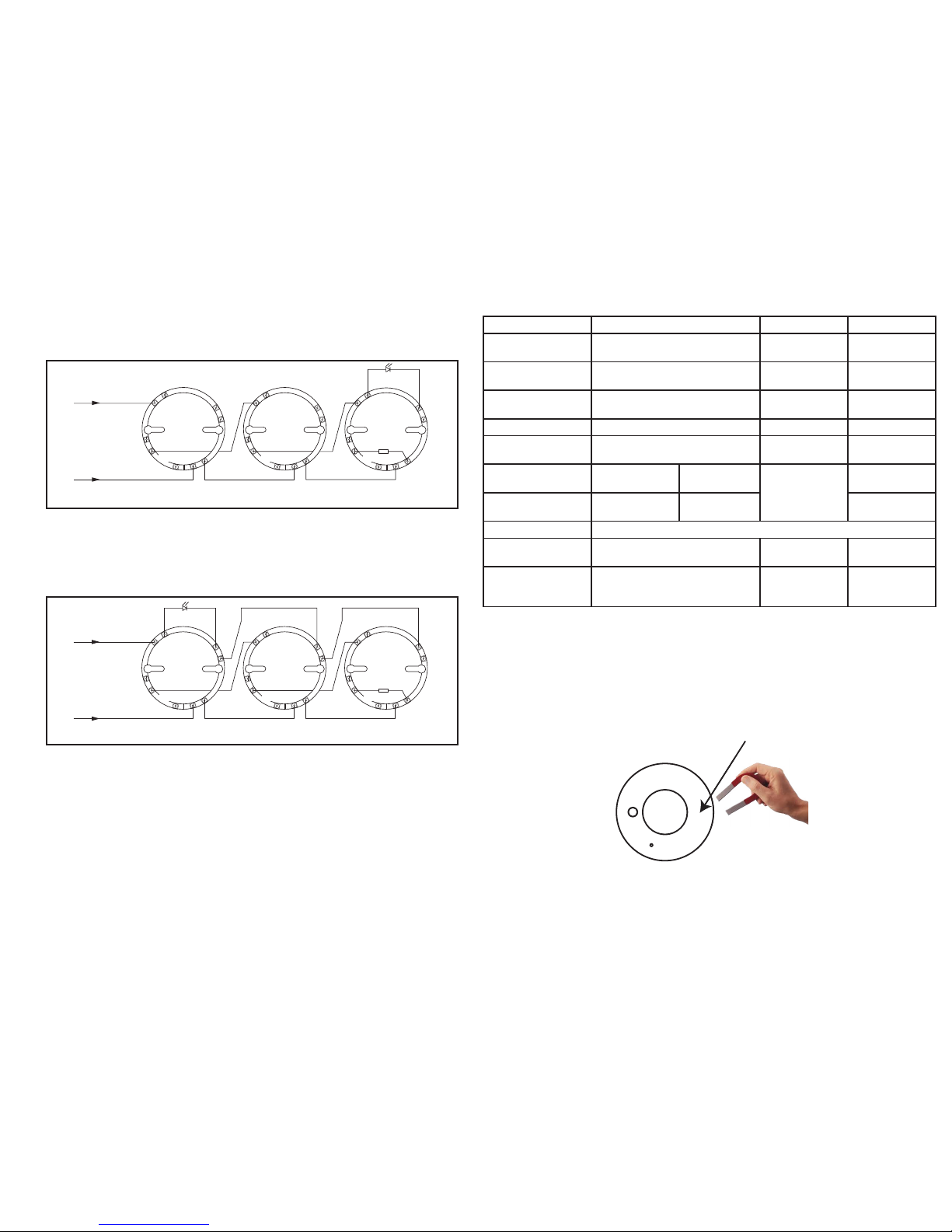
Fig 1. Wiring diagram of MIR-65 Series zone
Fig 2. Wiring diagr am of MIR-65 Series zone with co mmon remote indic ator
Fr
om control panel
L2
L
1
IN
–R
L1OUT
L2
L
1
IN
–R
L1OUT
L2
L
1
IN
–R
L1OUT
End-of-line
device
Remote LED
+
–
SHIELD SHIELD SHIELD
L
1
IN
–R
L1OUT
L2
L
1
IN
–R
L1OUT
L2
L
1
IN
–R
L1OUT
End-of-line
device
From control panel
L2
+
–
SHIELD SHIELD SHIELD
Remote LED
Warning
CAU TIO N: Do not use looped wire under terminal L2. Break wir e run to provide
supervision of conne ctions.
The above instructions cover the following base model:
MSB-65B 6” E-Z Fit base
Technical Data
Detector model # MHD-65-135, MHD-65-200 MID-65I MPD-65P
Detector type Heat Rate-of-Rise/Fixed
Temperature
Ionization Photoelectric
Working voltage 9–33V dc 9–33V dc 9–33V dc
Maximum alarm
current
17mA at 9V, 52mA at 24V 17mA at 9V,
52mA at 24V
17mA at 9V,
52mA at 24V
Surge current 0mA 0mA 0mA
Supervisory
current
40–50μA at 9V, 45–55μA at 24V 40–50μA at 9V,
45–55μA at 24V
40–50μA at 9V,
45–55μA at 24V
Heat element
rating
MHD-65-135 Ordinary
(135º F/57 ºC)
N/A N/A
MHD-65-200 Intermediate
(200ºF/93ºC)
Control panel UL/ULC L isted Compatible Contr ol Panel
Test method Magnet or hair dryer Magnet or
Gemini 501
Magnet or
Gemini 501
Installation
temperature
Minimum 32ºF (0ºC) Maximum
at least 20ºF (11ºC) below
rating
Minimum 32ºF
(0ºC) Maximum
158ºF (70ºC)
Minimum 32ºF
(0ºC) Maximum
140ºF (60ºC)
Control Panel Compatibility
For details of compatible control panels, please contact Mircom directly.
Performing the Magnet Test
Place the magnet near the detector on the OPPOSITE side of the LED.
Fig 3. Performing a magnet test o n the MIR-65 series detec tors.
LED
PLACE MAGNET HERE
 Loading...