

Page 1

Installation Instructions for Replacement
MD-1244 Microphone
The kit consists of the following parts:
• MD-1244: microphone circuit board with ad he siv e str ips on flat side
• wiring harness
You will also need the following tools:
• Screwdriver or a utility knife
• A multimeter probe
To install the microphone, you must perform the following steps:
A. Shut down the unit and disconnect power
B. Remove the old microphone
C. Attach MD-1244 to the door
D. Connect the wiring harness
Details on how to perform these steps are in the following pages.
A. Shut down the unit and disconnect power
It is essential that you follow the proper shut do w n pro c edu re .
To shut down the TX3 Touch Screen:
1. At the Touch Screen terminal, enter 9999.
2. Enter your administrator password, and then press OK.
3. Select File > Shut down > Shut down.
4. After the TX3 Configurator and Windows have finished shutting down, di sconnect power
from the Touch Screen.
LT-6652 Rev 0 Page 1 of 4
Page 2
B. Remove the old microphone
1. Open the door.
2. Use a screwdriver or utility knife to remove the old microphone circuit board from the
inside of the Touch Screen door.
3. Clean any residue left behind.
Figure 1 Old microphone on the Touch Screen door
4. Disconnect the old microphone cable.
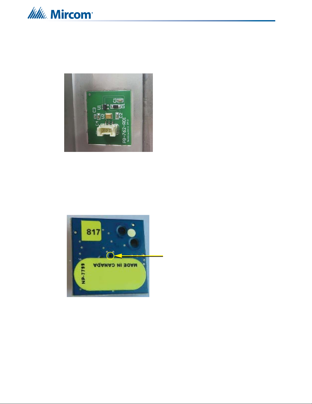
C. Attach MD-1244 to the door
The MD-1244 attaches to the inside of the Touch Screen door with double-sided tape. The
microphone fits into an indentation in the door. For ideal sound quality, the microphone
opening on the flat side of the MD-1244 (see Figure 2) must align with the microphone
opening on the door.
Figure 2 Location of the microphone opening on MD-1244
Microphone opening on
MD-1244
LT-6652 Rev 0 Page 2 of 4
Page 3

Align and attach the MD-1244 to the Touch Screen door using a multimeter probe:
Terminal for the
wiring harness
1. Expose the adhesive on the double-sided tape that is attached to the flat side of the
MD-1244 board.
2. Open the door.
3. From the front of the door, insert the multimeter probe through the door’s microphone
opening.
4. Carefully insert the tip of the multimeter probe into the microphone opening on the MD-
1244.
The microphone on the other side of the opening is very delica te. Permanent dama ge to
the microphone can result if you force the tip of the multimeter probe too far into the
microphone opening.
5. Align the MD-1244 so that the terminal for the wiring harness is on the bottom (see
Figure 3).
Figure 3 Proper alignment of the of the MD-1244 board
6. Using the multimeter probe as a guide, move the MD-1244 towards the door until the
MD-1244 attaches to the door.
Figure 4 Aligning the MD-1244 with the microphone hole
7. Go to the section D. Connect the wiring harness below.
LT-6652 Rev 0 Page 3 of 4
Page 4

D. Connect the wiring harness
+
Speaker
Connection
-
White
Microphone
Connection
Red Black
Unused
Unused
JW11
open
Sheild
Connect the wiring harness to the MD-1245 lobby controller board
1. Connect the 4-pin connector on the wiring harness to the 4-pin terminal on the lobby
controller board as shown in Figure 5.
2. If there is a jumper on JW11, remove it (see Figure 5).
3. Reconnect power to the unit, and then turn it on.
Figure 5 Microphone wiring on MD-1245
LT-6652 Rev 0 Page 4 of 4
 Loading...