

Mircom MCS-6001SV, MCS-6000H, MCS-6240, MCS-6240H, MCS-6001SHV Installation, Programming, And Troubleshooting Manual
...
®
9500 Series
NSL No Subscriber Line Access Systems
Scrollin g & N o n -S cro llin g D ire cto ry
INSTALLATION, PROGRAMMING,
and TROUBLESHOOTING MANUAL
L NOTICE
All information, documentation, and specifications contained in this manual are subject to change
without prior notice by the man ufa cturer.
©1998 by Mircom Technologies Limited
Printed in CANADA, June 30, 1998
LT-4 6 2 re v.6

TABLE of CONTENTS
IMPORTANT NOTICE 1
SYSTEM FEATURES 2
IN TR ODU C TION 3
SPECI FICATI ONS 3
OPERATION 3
SYSTEM BLOCK DIAGRAM:
Single Entrance Application 5
Multiple Entrances Application 6
Multiple Building Application 7
PRE-INSTALLATION PLANNING:
Entry or Lobby Panel Types 8
Controllers 9
Op tiona l P ro gra mming S oftw a re K it (us ing IB M PC), Mode l R S -4 8 5IM 9
Decoder/Relay Cabinets 10
Site Selection 10
Power Supply Requirements 10
W iring Requirements 10
CA-71A BIX Block or RJ-71C Punch-down Block Wiring Configuration 11
Door Strikes 11
Post Office Lock 11
ENCLOSURES AND ACC ESSO RIES INSTALLATION INSTRUCTIONS:
Semi-Flush Trim Ring Installation 12
Mounting the UNIVERSAL Type Lobby/Entry Panels 13
Mounting the Magnetic Letter Kit (MLK-040) 13
Mounting the Thermostat Heater Kit Model TH-101 14
Mounting the CONTINENT AL T ype Lobby/Entry Panels 15
Mounting the Magnetic Letter Kit (MLK-070) 16
Mounting the Decoder/Relay Cabinet 17
ELECTRONIC MOD ULES INSTALLATION INSTRUCTIONS:
Mounting the 9501A, 9502A or 9503 Controllers 18
Mounting the MD-345 Auxiliary Relay Board 18
Relay Cards Model 9512 Installation 18
SYSTEM WIRING INSTRUCTIONS:
W iring the 9501A (Main Controller) to 9508 or 9516 (Relay Cabinets) 18
Relay Cabinet's Decoder/Mother Board Jumper Configuration 19
W iring the Door Strike 19
W iring the Electromagnetic Door Lock 20
W iring the Lock-Back Switch 20
W iring the Door Override (Postal Lock & Fire Alarm) 21
W iring the Music Source to 9501A Controller 21
W iring the Auxiliary Relay and Main Entrance Active Relay Contacts 22
W iring the System and Lamp Supplies 22
W iring Instruction for Multiple Entrances Application 23
W iring the Guard Telephone to 9501A Controller 23
W iring the Speaker, Mic., and Keypad/Display Assembly 24
W iring to Earth Ground 24
W iring the Dedicated Telephone Line (Outside Line) 24
POWERING TH E SYST EM 24
®

ELEVATOR REC ALL (REST R ICTION) FEAT UR E 25
PROG RAM M ING INST RU CT IONS: Scrolling Dir. Non-Scrolling
Entering Programming Mode . . . . . . . 28 40
Direct Access Programming Codes Table . . . . 29 41
"No Manual" Menu Driven Programm ing Using *888 . . . 30 41
Manual Entry of Residents’/Tenants’ Dial Codes and Relay # . 30 42
Entry, Review, Edit or Delete Dial Codes or
Residents’/Tenants’ Names . . . . . . . . . . 31 42
Auto Programming the Residents’ Dial Codes . . . . 32 43
Programming the Keyless Entry Codes . . . . . . 32 43
Review and Delete Keyless Entry Codes . . . . . 33 44
Reprogramming Master Code . . . . . . . 33 44
Set Door Timer . . . . . . . . . . . . 34 45
Elevator Recall . . . . . . . . . . . . 35 45
Set On-Line Timer . . . . . . . . . . . 35 45
Multiple/Single Entrance Select . . . . . . . . 35 46
Ring Cycle Select . . . . . . . . . . . 36 46
Set Clock............. 37 47
Two 11-digit Telephone Number Entry . . . . . . 37 47
Ring Pattern Select . . . . . . . . . . . 38 47
Sort Residents' Names . . . . . . . . . . 38 --
Select Digit for Hold . . . . . . . . . . 39 48
MASTER CODE RESET ................40
REPLACEMENT:
Lamp Replacement (Universal type lobby panels only) . . . . . . 22
Fuses Replacement . . . . . . . . . . . . . 39
SYSTEM ADJUSTMENT S:
Music Level Adjust . . . . . . . . . . . . . . . 49
Microphone Volume . . . . . . . . . . . . . . 49
Speaker Volume............... 49
Pulse Sensitivity Adjust . . . . . . . . . . . . . . 49
Display Contrast Adjustment . . . . . . . . . . . 50
TROUBLESHOOTING.................51
APPENDICES:
A-1: CA-71A BIX Block W iring configuration . . . . . . . . 52
A-2: RJ-71C Punch Down Block W iring Configuration . . . . . . 53
B-1: CA-71A BIX Block Identification Form . . . . . . . . 54
B-2: RJ-71C Punch Down Block Identification Form . . . . . . 55
C: Accessory Specifications . . . . . . . . . . . . 56
D-1 and D-2: Directory Worksheets . . . . . . . . . . 57,58
E: Character Set Table . . . . . . . . . . . . . . 59
RESIDENT O PER AT ING INSTR UC T IONS . . . . . . . . . . . . 60
WARRANTY.................. .61

IMPORTANT NOTICE
Notice for all 9500 series Telephone Entry Systems Sold in Canada:
The Canadian Department of Communications label identifies certified equipment. This certification means that the equipment
meets certain telecommunications network protective, operational and safety requirements. The Department does not
guarantee the equipment will operate to the user's satisfaction.
Before installing this equipment, users should ensure that it is permissible to be connected to the facilities of the local
telecommunication company. The equipment must also be installed using an acceptable method of connection. The customer
should be aware that compliance with the above conditions may not prevent degradations of service in some situations.
Repairs to certified equipment should be made by an authorized Canadian maintenance facility designated by the supplier.
Any repairs or alteration made by the user to this equipment, or equipment malfunctions, may give the telecommunications
company cause to request the user to disconnect the equipment.
Users should ensure for their own protection that the Earth Ground connections of the power utility, telephone lines and
internal metallic water pipe system, if present, are connected together. This is necessary both for proper operation and for
protection.
CAUTION: Us e rs sh o uld no t atte mpt to m a k e s u ch c o nn e c tions the mselv es , b ut s h ou ld c o nta c t the ap p ro pria te
electric inspection authority, or electrician, as appropriate.
NOTICE:
The LOAD NUMBER (LN) assigned to each terminal device denotes the percentage of the total load to be connected to a
telephone loop which is used by the device, to prevent overloading. The termination on a loop may consist of any
combination of devices subject only to the requirement that the sum of the load numbers of all devices does not exceed
100.
INDUSTRY CANADA (Formerly D.O.C.) Registration Number: 1156 6200 A
Notice for all 9500 series Telephone Entry Systems Sold in the U.S.A.:
This equipment has been tested and found to comply with the limits for a class A digital device, pursuant to Part 15 of the
FCC Rules. These limits are designed to provide reasonable protection against harmful interference when the equipment
is operated in a commercial environment. This equipment generates, uses, and can radiate radio frequency energy and,
if not installed and used in accordance with the instruction manual, may cause harmful interference to radio
communications. Operation of this equipment in a residential area is likely to cause harmful interference in which case
the user will be required to correct the interference at his own expense.
WARNING:
Changes or Modifications not expressly approved by MIRCOM TECH NO LO G IES LTD. could void the users’
autho rity to op e ra te th e e q uip ment.
F.C.C. Registration Number: 1M8CAN-21269-D T-E
Notice for all 9500 series Telephone Entry System Sold Internationally:
Conformity to the local Tel. Co. standards must be reviewed before installation of 9500 Series Telephone
Access Systems.
MIRCOM TECHNOLOGIES LIMITED, 9500 Series: No Subscriber Line Page 1

SYSTEM FEATURES
SCROLLING DIRECTORY FEATURES: NON-SCROLLING DIRECTORY FEATURES:
T SCROLLING DIRECTORY T Capacity for up to 1000 Suites or Telephone Lines.
T Programmable using the lobby panel’s keypad T Programmable using the lobby panel’s keypad
T 15 Characters Resident Name length. for Residents plus five (5) spares for use of
T Capacity for up to 1000 Suites or Telephone Lines. building management.
T 1000 reprogrammable KEYLESS ENTRY codes TSUPERTWIST 2 lines by 16 characters backlit
T 4 lines by 20 characters VFD (Vacuum Fluoresc ent Dis play)
COMMON FEATURES FOR BOTH SCROLLING AND NON-SCROLLING TEL. ACCESS SYSTEMS:
T No SUBSCRIBER PHONE LINE FEE is required.
T User programmable MASTER CODE for sec urity
T Capability of rotary "PULSE" or touch tone "DTMF" dialling.
T VARIABLE RESIDENT CODE LENGTH, 1, 2, 3 or 4 digit.
T SINGLE or MULTIPLE ENTRANCES capabil ity.
T DOOR OVERRIDE connection for fire alarm. Doors will
T Built-in POST OFFICE LOCK micro switch.
T Connection for "LOCK-BACK" door contact to lock door
T MAIN ENTRANCE ACTIVE RELAY CONTACTS for use
T AUXILIARY RELAY CONTACTS for use of auxiliary
T User Definable Start Number for auto-programming
T Programmable "DOOR OPEN" timer (99 seconds max.).
T Programmable "ON LINE or CONVERSATION TIME"
T Adjustable number of RING CYCLES.
T Built-in CALL WAITING feature.
T MUSIC-ON-HOLD input for music source (mono) such
TNONVOLATILE MEMORY (EEPROM), retains programmed
T GUARD or CONCIERGE telephone connection. Use for
T DEDICATED TELEPHONE LINE, allows to dial 2 telephone
T Stainless Steel or Painted Vein (textured) lobby panels
(Universal or Continental type enclosures).
T Watch Dog Timer circuit to automatically reset the unit to
T Compact, small, and easy to install Decoder/Relay Cabinets
®
or IBM PC T 1000 reprogrammable KEYLESS ENTRY codes
for Residents plus five (5) spares for use of extended temperature LCD display.
building management.
and programming access.
pulse open during emergency.
as soon as it is open to prevent "tailgating" through.
of camera activation.
entrance or garage door.
the Residents’ access codes.
timer (99 seconds max.).
as radio or tape deck.
information during power failure.
calling the Residents or Suites.
numbers of up to 11 digits.
eliminate system latch-up.
with LED indicator for each phone line. Ideal for installers
and troubleshooting.
MIRCOM TECHNOLOGIES LIMITED, 9500 Series: No Subscriber Line Page 2

INTRODUCTION
MIR C OM 'S 9 5 00 S e ries E ntry S yste ms p ro vide s a h igh qu a lity two wa y co mmunic atio n b e twe e n the res id en ts
and their visitors in a multi-unit dwelling establishment. The system uses the existing phone lines for
comm unication and access control. The system does not require a subscriber phone line since it uses the existing
phone line wiring. No expensive installation costs are incurred compared to traditional hardwired intercom
systems. Its versatile design is loaded with standard features such as call waiting, metal keypad, multiple entrance
ca p a b ility, a n d p r o v is io n f o r p osta l lo c k. T h e s ys tem lo b by pan els a re a v a ila b le in h e avy ga uge n o n ma g n e tic
stainless steel or painted vein (textured) finish. Surface or Flush mount applications are available by selecting the
appropriate enclosure type (Universal or Continental, see page 7). Installation is quick and easy featuring a low
voltage operation and complete system programmability using the lobby panel’s keypad or IBM PC .
† Trademark of International Business Machine personal computer
® †
SPECIFICATIONS
The operating temperature range is 50 °C (122 °F) to -20 °C (-4 °F). It is necessary that an optional TH-101
Thermostat Heater be installed when the ambient temperature falls below 0 °C (32 °F)
Power Supply Voltage Range is 105 to 128 VAC.
Us e L o op S ta r t p h o n es o n ly (n o t Gro u n d Sta r t p h o n e s ), ch e c k with you r lo c a l telep h o n e c o mp a n y.
OPERATION
STANDARD OPERATION FOR SCRO LLING DIRECTO RY UN ITS:
Visitor calling the Res iden t:
At th e e n tr y p o in t ( lo b b y) , th e v is itor loc a tes th e Res id e n t’s Dial Code and Name by scrolling through the directory
list displayed on the screen by using the * or # keys. Pressing the * or # key mom entarily will scroll the list "up or
down" one name at a time. Holding the * or # key will scroll the list "up or down" continuously and stop scrolling
when the key is released. A known Dial Code can b e e n te r e d d ir e c tly o n keyp a d w ith o ut sc r o llin g . When a c a ll is
placed, a distinguishable ring notifies the resident that a visitor is calling. While talking to the visitor, the resident
m a y d ia l "9" to o p e n the ma in d o o r o r h a n g - u p th e ph o n e to r e fuse e n tr y.
STANDARD OPERATION FOR NON -SCROLLING DIRECTO RY UNITS:
Visitor calling the Res iden t:
At the entry point (lobby), the visitors locates the Resident’s Dial Code on the direc tory a nd e nte rs the a pp ro p riate
code number on keypad. When a call is placed, a distinguishable ring notifies the resident that a visitor is calling.
Wh ile ta lk in g to th e v is ito r , th e r e s id e n t ma y d ial "9" to op e n th e ma in d o o r o r h ang -u p the p h o n e to ref u s e e n tr y.
NOTE: Residents’ telephones must be capable of generating a touch tone (DTMF) or rotary "PULSE" signal for
the digit "9" for the door release circuit to activate.
OPERATION FOR AUXILIARY RELAY OUTPUT:
If the auxiliary relay output is used for control of garage or dock doors, the resident can activate or release the
auxiliary door by pressing the number "6". This function is available by using a touch tone (DTMF) type
tel ephones. No provision for Pulse (rotary) type telephones.
OPERATION FOR GUARD or CON CIERGE LINE:
The Guard can call the residents or suites by simply dialling * key followed by the resident's Dial Code . Also, the
MIRCOM TECHNOLOGIES LIMITED, 9500 Series: No Subscriber Line Page 3

Guard can release the door by pressing the # key to a llo w en try. This function is available by using a touch tone
(DTMF) type telephones. No provision for Pulse (rotary) type telephones.
Call Waiting Feature:
All 9500 S e ries s yste ms ha s a b u ilt-in two -w ay c all wa iting fe a tu re th a t no tifies the res id en t (u sin g th e ph o ne ) w ith
a distinct tone that an incoming caller is waiting. The resident may answer the call by flashing the hook switch.
There are two possible scenarios or situation exists here and are described below.
1. Th e vis ito rs p lac e d a c a ll w h ile th e re s id en t is o n th e p h o n e (c o n ve rs in g with o u ts id e p a rty ):
In this situation, the resident will hear a distinct tone meaning that a visitor is calling from the lobby. The resident
can answer the call by simply flashing the hook switch. This action will automatically put the outside party “on
hold”. While talking to th e visitors , th e re s ide n t ca n allow e ntry b y dialling th e d igit "9" to o p en the main d o or o r to
refus e en try simply flash th e h o ok s w itch o r dia l digit “4". Either action will reconnect the resident to the outside
party (pre vio us ly pu t “on h old ”) to co n tinue th eir c o nv ers a tion .
2. The resident received an outside call while talking to the visitors in the lobby:
In this situation, the resident will hear a distinct tone meaning that an outside line caller is waiting. There are two
ways to an s w e r this ca ll. On e is to ha n g u p the ph o ne b y simply flash ing the ho o k s w itch or d ial the d igit “4"
(refus ing e ntry). T h e s ec o n d is b y dialling th e digit "9" w h ic h w o u ld a llo w en tr y. B o th ac tio n s will automatic a lly
con ne c t the re sid en t to th e ou ts ide line. P lea se n ote tha t the re sid en t cannot put the visitors on hold because
of the a llow ab le ta lk -time lim it of the s yste m.
MIRCOM TECHNOLOGIES LIMITED, 9500 Series: No Subscriber Line Page 4
SYSTEM BLOCK DIAGRAMS
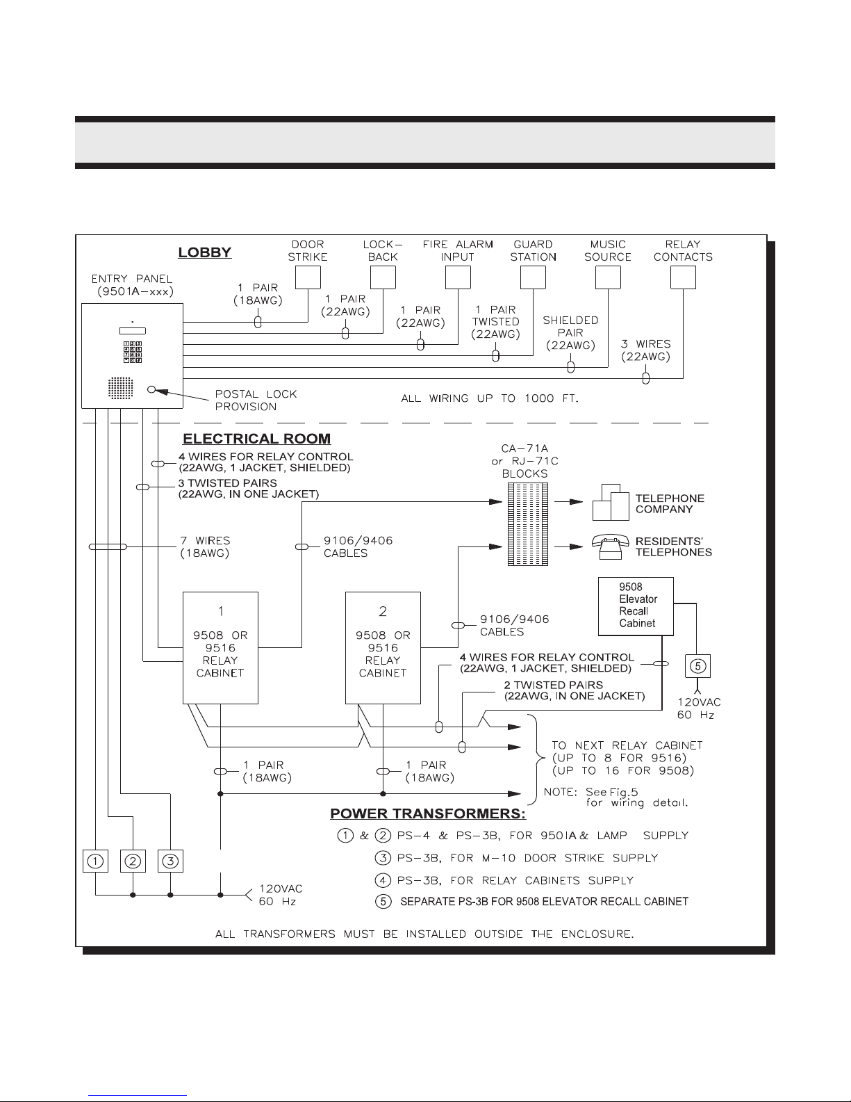
SINGLE ENTRANCE APPLICATION:
MIRCOM TECHNOLOGIES LIMITED, 9500 Series: No Subscriber Line Page 5
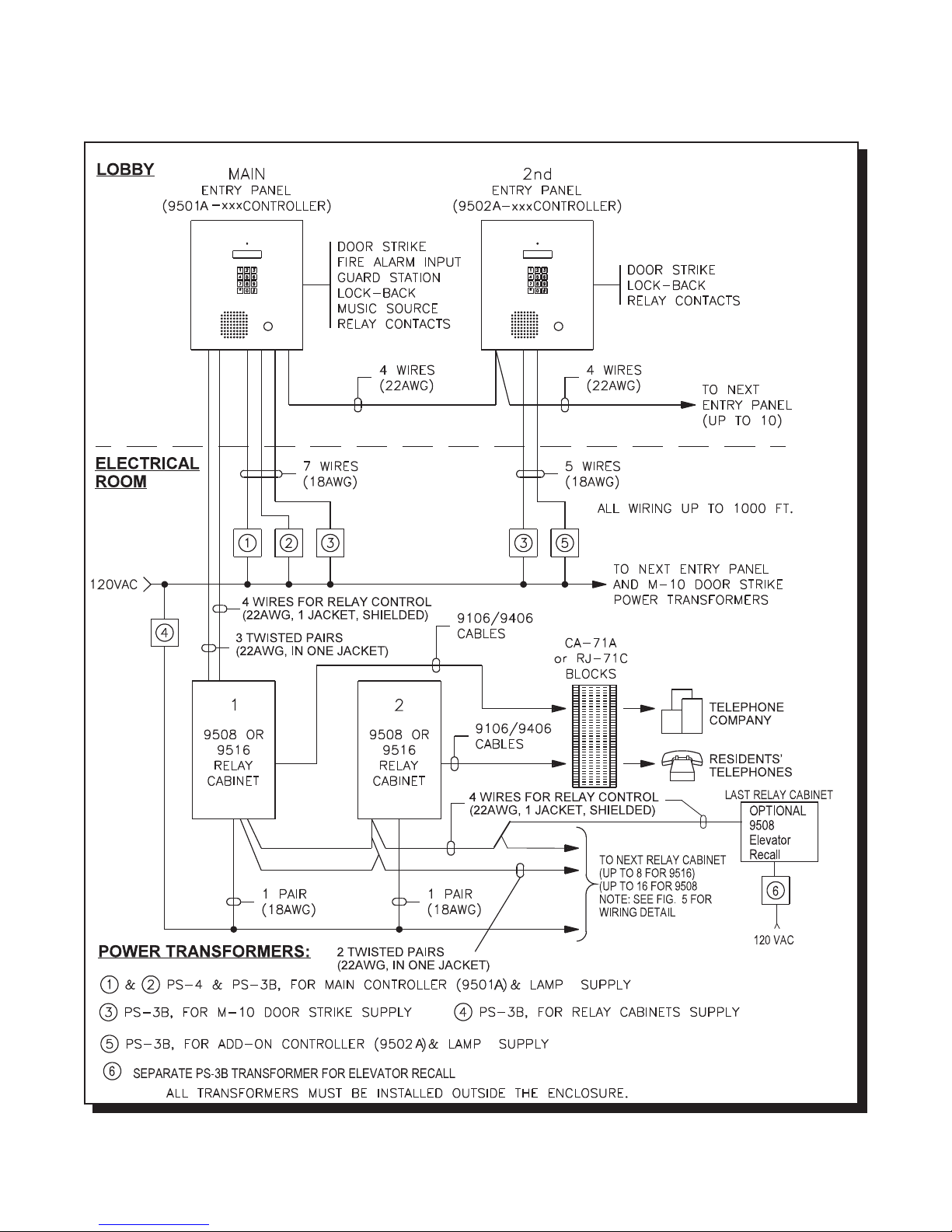
MULTIPLE ENTRANCES APPLICATION:
MIRCOM TECHNOLOGIES LIMITED, 9500 Series: No Subscriber Line Page 6
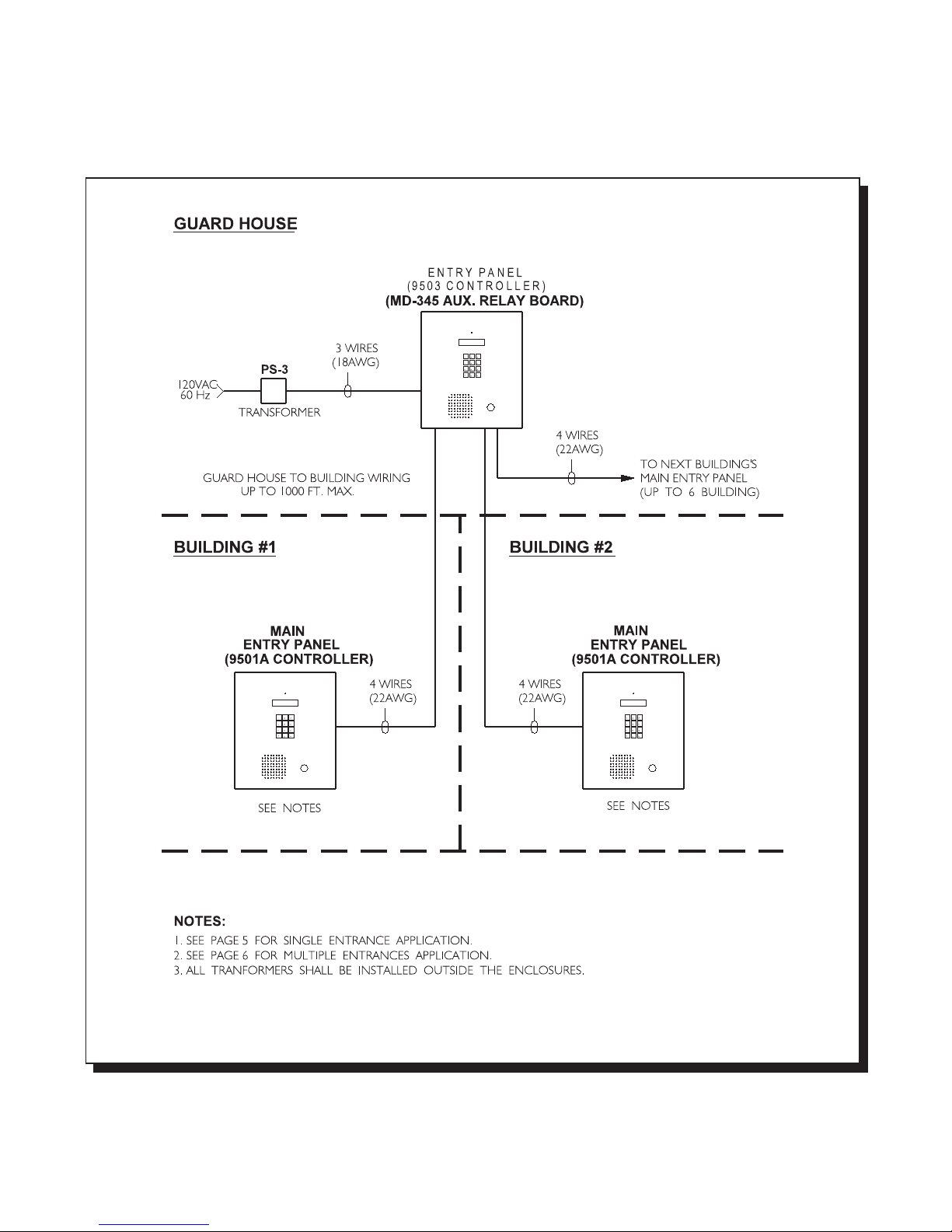
MULTIPLE BUILDING APPLICATION:
MIRCOM TECHNOLOGIES LIMITED, 9500 Series: No Subscriber Line Page 7

PRE-INSTALLATION PLANNING
Before the actual installation begins, the system requires various items to be pre-arranged and are described
below :
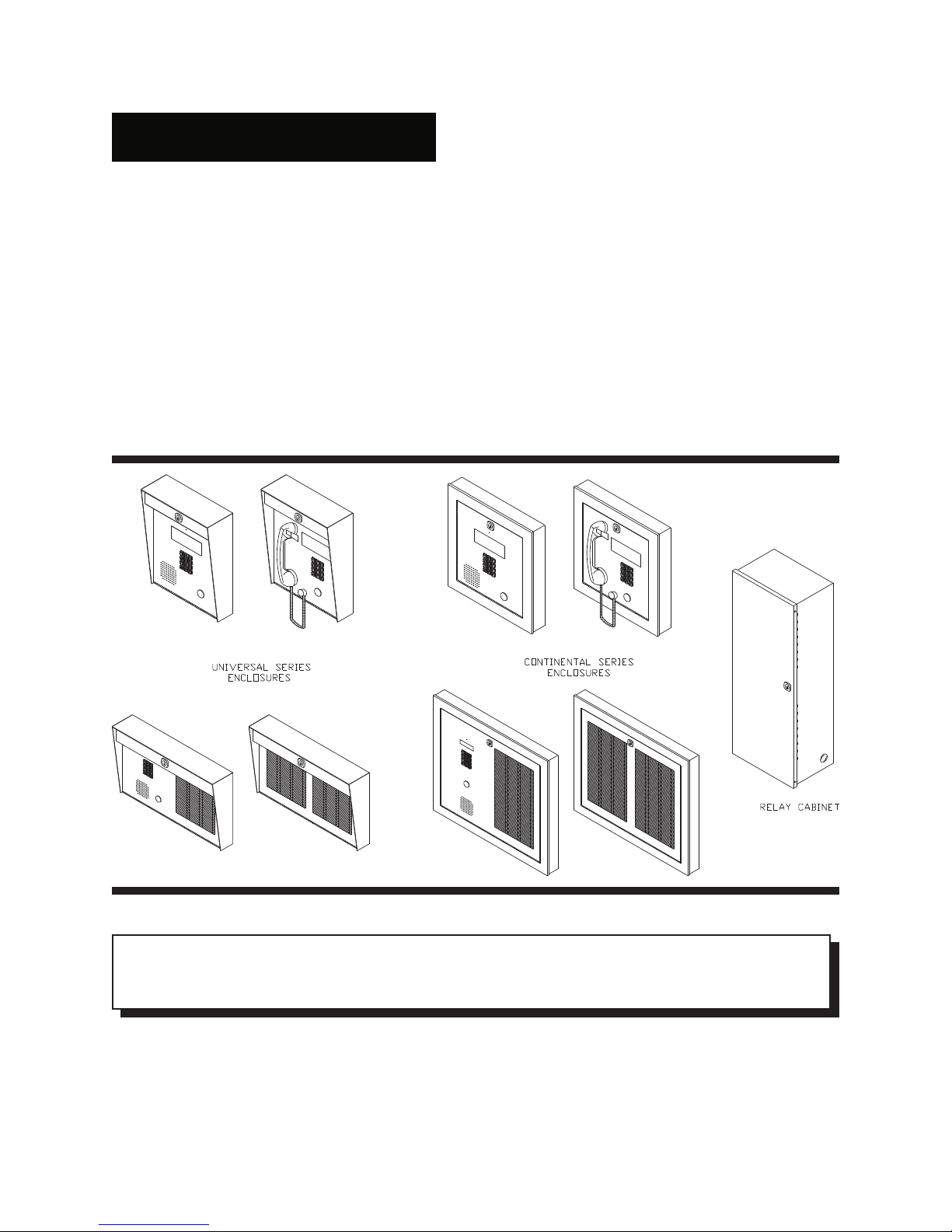
1. ENTRY OR LOBBY PANEL TYPES
The UNIVERSAL series entry/lobby panels are hooded surface mount enclosures with built-in lighting for outdoor
or in d o o r a p p lic a tions . Optio nal flu s h tr im rin g s are a v a ila b le f o r s e mi-f lu s h in s tallatio n s . The r e a r e s ix (6) mod e ls
available and are listed below:
Universal Panels for Scrolling Directory:
Model MUS-5000SV ± S ta in less S teel fin is h e n tr y p a nel co me s with keyp a d , 4 x 2 0 VF D dis p la y,
micropho ne , speak er, and micro switch for postal lock. No controller.
Model MUS-5000SHV ± Stain le s s S teel fin is h en try p ane l c o me s w ith keyp a d , 4 x20 V F D dis p la y,
armou red ha nd set, and micro switch for postal lock. No controller.
Universal Panels for Non-Scrolling Directory:
Model M US-5000 ± Stainles s S teel fin is h e n tr y p a nel com e s with keyp a d , 2 x 16 L C D dis p la y,
microphone, speaker, and micro switch for postal lock. No directory and
controller.
Model M US-5000H ± Stainles s S te e l finish en try pa n el co mes w ith k e ypa d, 2 x 16 L C D d isp lay, ha n ds e t,
and m icro sw itch for postal lock. No directory and controller.
Model M US-5120 ± Stainles s S teel fin is h e n tr y p a nel com e s with keyp a d , 2 x 16 L C D dis p la y,
microphone, speaker, micro switch for postal lock, and paper directory for 120
names . N o c o ntro ller.
Model M US-5120H ± Sta in le s s Ste e l f in is h e n tr y p a n e l c o me s with k e ypad , 2 x 1 6 L CD dis p la y,
handset, micro switch for postal lock and paper directory for 120 names. No
controller.
Accessories:
Model MUFT -5000P ± Flush trim ring for MU S -5000 /H/S/SH pa nels.Painted black (textured).
Model M UFT -5120P ± Flush trim ring for M U S-51 20/H , and M P D -5240 pane ls. Painted black (textured).
M od el MPD -5120 ± Stain le s s S teel a d d - o n p a p e r d ire c tory pa nel, 1 2 0 n a me s c a p a city.
Model M PD -5240 ± Stain le s s S teel a d d -on p a p e r d ir e c tory pa n e l, 240 n a me s c a p a c ity.
Model M LK -040 ± Magn e tic s trips dire c tory k it, 40 na mes ca p a city. It comes w ith p las tic letters,
magnetic strips, brackets, and hexnuts.
Model TH-101 ± Therm os tat heater.
Note: P ainted Silver, Gold & C oppe r Ve in lobby pane ls are available by custom orde r.
MIRCOM TECHNOLOGIES LIMITED, 9500 Series: No Subscriber Line Page 8

The CONTINENTAL series entry/lobby panels are designed for indoor applications only. These elegant lobby
panels c a n b e mo u n te d e ither f lu s h o r s u r fa ce b y s e le c tin g the a p p ropria te ba c kbo x . The r e a re six (6 ) mo d e ls
available and are listed below:
Continental Panels for Scrolling Directory:
Model MCS-6001SV ± S ta in less S teel fin is h e n tr y p a nel co me s with keyp a d , 4 x 2 0 VF D dis play,
micropho ne , speak er, and micro switch for postal lock. No controller.
Model MCS-6001SHV ± Stain le s s S teel fin is h en try p ane l c o me s w ith keyp a d , 4 x20 V F D dis p la y,
armou red ha nd set, and micro switch for postal lock. No controller.
Continental Panels for Non-Scrolling Directory:
Model M CS-6000 ± Stainles s S teel fin is h e n tr y p a nel com e s with keyp a d , 2 x 16 L C D dis p la y,
microphone, speaker, and micro switch for postal lock. No directory and
controller.
Model M CS-6000H ± Stainles s S te e l finish en try pa n el co mes w ith k e ypa d, 2 x 16 L C D d isp lay, ha n ds e t,
and m icro sw itch for postal lock. No directory and controller.
Model M CS-6240 ± Stainles s S te e l finish en try pa n el co mes w ith k e ypa d, L C D d isp lay,
microphone, speaker, micro switch for postal lock, and paper directory for 240
names . N o c o ntro ller.
Model M CS-6240H ± Stainle ss S te el finis h e n try pa ne l co mes with k eyp ad , L C D d isp lay,
handset, micro switch for postal lock and paper directory for 240 names. No
controller.
Accessories:
Model MPD-6240 ± Add -o n pa p e r d ir e c tory pa n e l, 240 n a me s c a p a city.
Model M PD -6480 ± Add- o n p a p e r d ir e c to r y p a n e l, 4 8 0 na me s c a p a c ity.
Model BBF-6001 ± Flush b a ckbox fo r M CS-6 00 1 S /S H . S atin co a t finish .
Model BBS-6003 ± Surface b ack bo x for M C S -6001 S/SH . Painted black (textured).
Model BBF-6101 ± Flush backbox for MCS-6000, MCS-6000H, and MPD-6120 panels.
Model BBF-6102 ± Flush backbox for MCS-6240, MCS-6240H, and MPD-6480 panels.
Model BBS-6301 ± Surf a ce b a ckbox fo r M CS-60 0 0 , M C S -6 0 0 0H, and M P D -6 2 4 0.
Model BBS-6302 ± Surf a ce b a ckbox fo r M CS-62 4 0 , M C S -6 2 4 0H, and M P D -6 4 8 0 p a ne ls .
Model M LK -070 ± Magn e tic s trip d irec to ry kit, 70 n ames c a pa c ity. It comes w ith p las tic lette rs ,
magnetic strips, brackets, and hexnuts.
Note: Painted Silver, Gold & Copper Ve in lobby pane ls are available by cus tom order.
2. CONTROLLERS
SCROLL ING D IRECT O RY CO N TR O LLER S: For both LCD and VFD Display
Mo d e l 950 1-0 40 A ± M a in Con tr o lle r . 4 0 n a me s c apa c ity.
Mo d e l 950 1-1 20 A ± M a in Con tr o lle r . 1 2 0 n a me s cap a c ity.
Mo d e l 950 1-3 60 A ± M a in Con tr o lle r . 3 6 0 n a me s cap a c ity.
Mo d e l 950 1-8 00 A ± M a in Con tr o lle r . 8 0 0 n a me s cap a c ity.
Model 9502-040A ± A d d - o n Con tr o lle r f o r a u x ilia ry e n tr a n ce(s ) . 4 0 n am e s ca p a c ity.
Model 9502-120A ± A d d - o n Con tr o lle r f o r a u x ilia ry e n tr a n ce(s ) . 1 2 0 na mes ca p a c ity.
Model 9502-360A ± A d d - o n Con tr o lle r f o r a u x ilia ry e n tr a n ce(s ) . 3 6 0 na mes ca p a c ity.
Model 9502-800A ± A d d - o n Con tr o lle r f o r a u x ilia ry e n tr a n ce(s ) . 8 0 0 na mes ca p a c ity.
Note: M ake sure to order the proper lobby panels meant for scrolling directory.
Option al Prog ramming So ftw are Kit:
Model RS-485IM Interface Module, along with MSW-001 MirSoft TAS programming software, is an optional
programming kit to enable the user to upload or download residents’ names, dial codes, keyless entry codes,
and relay line numbers using a personal computer. This software can be used on IBM
PC /X T /2 8 6/3 8 6/4 8 6/P e n tium Co mpa tible P C u nd e r M S -DO S version 5 or h ig he r, Window s 9 5 or higher, OS/2
with Colour or Monochrome Text Screen (MDA, CGA, EGA, VGA, SVGA) capability and one serial port. To order
this kit, please consult our factory for further information.
®®®
®
MIRCOM TECHNOLOGIES LIMITED, 9500 Series: No Subscriber Line Page 9

NON -S C R O L LIN G D IRE C T O R Y C O N T R O L LE R S :
Mo d e l 950 1A ± Ma in C o n troller.1 0 00 re s ide nts c ap a c ity.
Model 9502A ± Add - o n Con tr o lle r f o r a u x ilia r y en tr a n ce(s). 10 00 re s id ents c a p acity.
Model 9503 ± Multi- B u ild ing Gua rd Hou s e Con tr o lle r . 1 0 0 0 r e s id e n ts ca p a c ity.
Accessory:
PCB Assy.: MD-345 ± Auxiliary 6 relay board. This module is intended for use of Multiple Building
Application or for applications where relay contacts are required for activation of
peripherals. Please contact our Engineering Field Support Personnel for detailed
wiring scheme and information.
Note: Make sure to order the proper lobby panels meant for non-scrolling directory.
3. DECODER/RELAY CABINETS
Model 9508 ± Decoder/relay cabinet can hold up to eight (8) relay cards or ninety six (96)
telephone lines. Relay cards not included.
Model 9516 ± Decoder/relay cabinet can hold up to sixteen (16) relay cards or one
hundred ninety two (192) telephone lines. Relay cards not included.
Accessories:
Model 9512 ± Relay Card interfaces up to 12 telephone lines.
Model 9512E ± Elevator Recall Relay Card provides up to 12 relay contacts.
Model 9106 ± 6 F t. A mp h e n o l Cab le . Stan d a r d f o r 9 5 0 0 Se ries s ys te ms . Use this c a b le
for CA-71A or RJ-71C configured BIX Block.
Model 9106E ± 6 Ft. A mphe n ol C a b le. U s e this c a ble fo r interf a cin g th e 95 0 0 s e ries s yste ms to
existing R J -7 1 A co n figu re d BIX Bloc k .
Model 9406 ± 6 F t. Octo p us R e la y Cab le . Use this c a b le f o r c u stom w irin g the te le p h o n e's T ip
and Ring by using the standard CA-38A (RJ-38A) modular jacks.
4. SITE SELECTION
The Entry Panel should be installed as near as possible to the controlled entry point. Do not install the system in a
location w he re th e L C D display is e x po s e d to dire c t su n light s inc e it will red uc e visib ility.
5. POWER SUPPLY REQUIREMENTS
Select the appropriate power transformers required by your system configuration. Below are the transformer
models that are available:
.
Mo d el PS-4 ± 16 V AC / 40 V A, C SA appro ved C lass 2 P ow er T rans former.
Model PS-3B ± 8 VAC/13 VA, 16 VAC/17 VA, 24 VAC/20 VA, CSA approved Class 2 Power
Transformer.
Model PS-13 ± 12VDC, 200mA.
6. WIRING REQUIREMENTS
Count the number of wires and identify the proper gauges that are required for your system configuration. For a
typical Sing le o r M u ltiple e ntra n c e a p plica tion , ple as e re fe r to p a ge s 5 a n d 6 . F or S ys tem B loc k D iag ra ms p ag e 7.
For custom applications, we recomm end consulting our Application Engineering personnel for evaluation.
MIRCOM TECHNOLOGIES LIMITED, 9500 Series: No Subscriber Line Page 10

7. CA-71A BIX Block or RJ-71C Punch Down Block Wiring Configuration
CA - 7 1 A (fo r Can a d a) an d RJ- 7 1 C (fo r U.S .A .) Wiring C o n f ig u ra tions o f B IX or Pun c h Dow n B lo c k ca n b e f o u n d in
Appendices A-1 and A-2 respectively. Normally, the required blocks are installed by the telephone company. Each
block serves up to 12 telephone lines. The 50 pins Amphenol connector on the BIX block is connected to the 9512
relay card using the standard 9106 cable. Contact the telephone company at least three (3) weeks in advance
before the actual installation and order the required blocks. Complete the CA-71A or RJ-71C Block Identification
Form in Appendix B-1 or B-2 (as required) for the phone installer. The form instructs the phone installer how the
phone lines should be wired to the BIX/Punch Down Blocks. If possible, all BIX Blocks should be installed as close
as possible to the 9508 or 9516 D ecod er/relay Cabinet(s).
Th e f o llo w in g in f o r ma tio n mu s t b e g iv e n to the T e le p h o ne C o mp a n y:
1. Telephone numbers of the lines to which the 9500 system will be connected.
2. The Industry Canad a (formerly D.O.C.) registration number 1156 6200 A for Canada.
3. The F.C .C. registration num ber 1M8CAN-21269-DT-E for U.S.A.
3. The ringer equivalence number (REN) of 9500 system is 0.0B.
Note: RJ-71C Wiring Configuration is not recognized by all telephone companies. For Bell Canada who has
jurisdiction for Ontario and Quebec, refer to CA-71A block for interconnect to the Telephone Entry systems.
Important notice:
Since there are two types of block wiring configuration, CA-71A and RJ-71C, we recommend the user contact the
Telephone Company as to what block wiring configuration is available. We suggest using Mircom's standard 9106
cab le fo r C A -7 1 A or RJ-71 C c o n figu re d b loc k s s inc e the y are stra ig ht fo rw a rd an d ea s y to us e .
8. DOOR STRIKES
Select the appropriate door strike as required by your system applications. We recommend using Mircom's door
strike s b e low an d its c ompa tible po w er tra n s fo rmer. S e e ap p en d ix "C " fo r d oo r s trik e s' s pe c ifica tion s .
Model M -10 ± D C (silent) or AC (buzzing) Door Strike. Us e PS -3B transformer.
Model M-10HD ± AC (buzzing) Heavy Duty Door Strike. Us e PS -3B transformer.
Model M -20 ± DC (silent) or AC (buzzing) Heavy Duty Door Strike. Us e PS -3B transformer.
Important notice:
The door strike must have its own separate power transformer. Do not tap or use the system power transformers.
Wh e n u s in g a d if feren t doo r s tr ike a n d d o o r s tr ik e tr a n sfor me r, t h e ma x imu m s trike lo a d th at m ay be s w itc hed
through the control unit is 28 VAC or DC, 3.0 Amp. Maximum .
9. POST OFFICE LOCK
Th e s ystem h a s a b u ilt- in mic ro s witch a n d mo u n ting h a r d w a r e fo r p o s tal loc k in s tallatio n . I f a p o stal s e r vice is
requ ired , co n tac t the P o s t O ffic e to o bta in th e loc k .
MIRCOM TECHNOLOGIES LIMITED, 9500 Series: No Subscriber Line Page 11
ENCLOSURES AND ACCESSORIES INSTALLATION INSTRUCTIONS
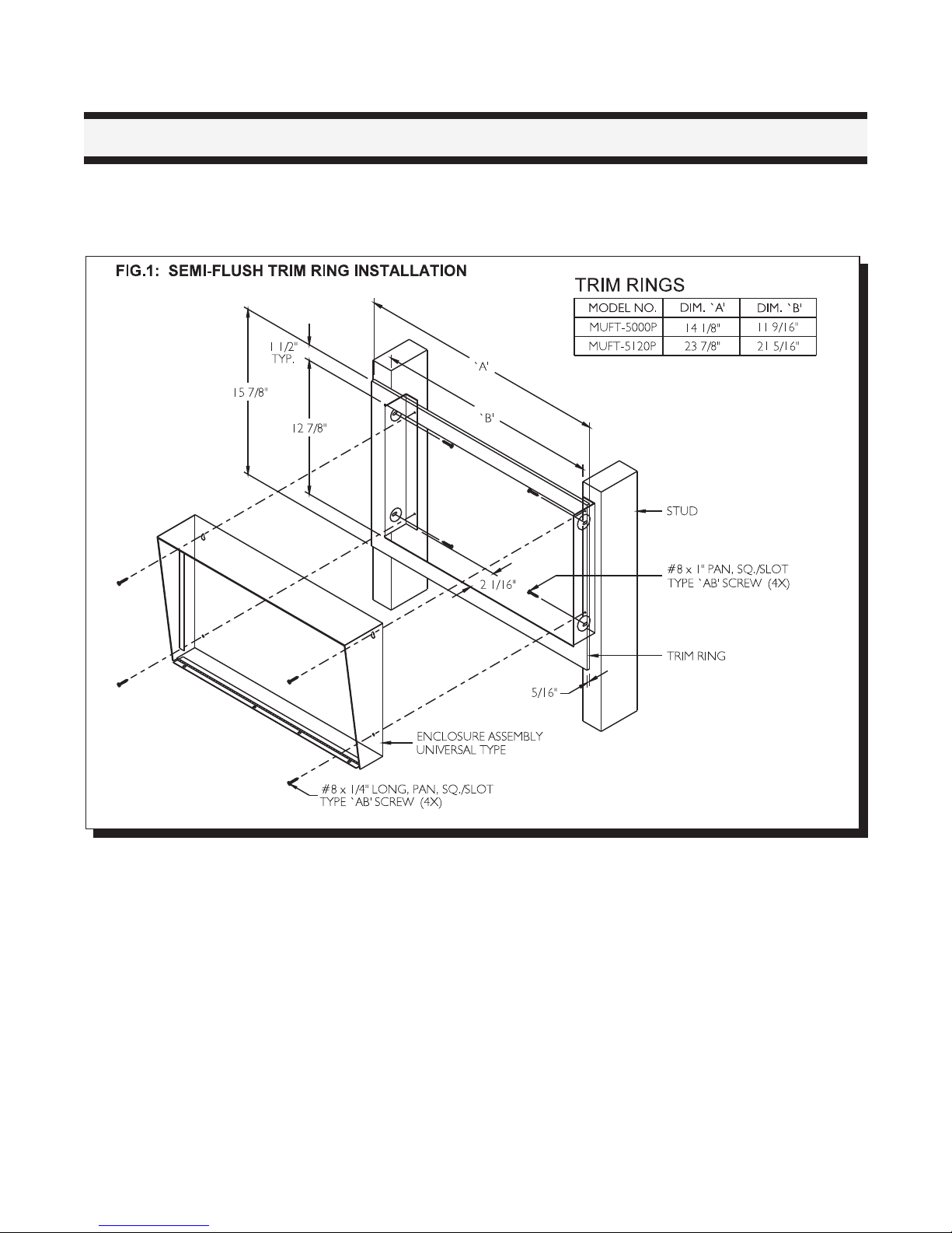
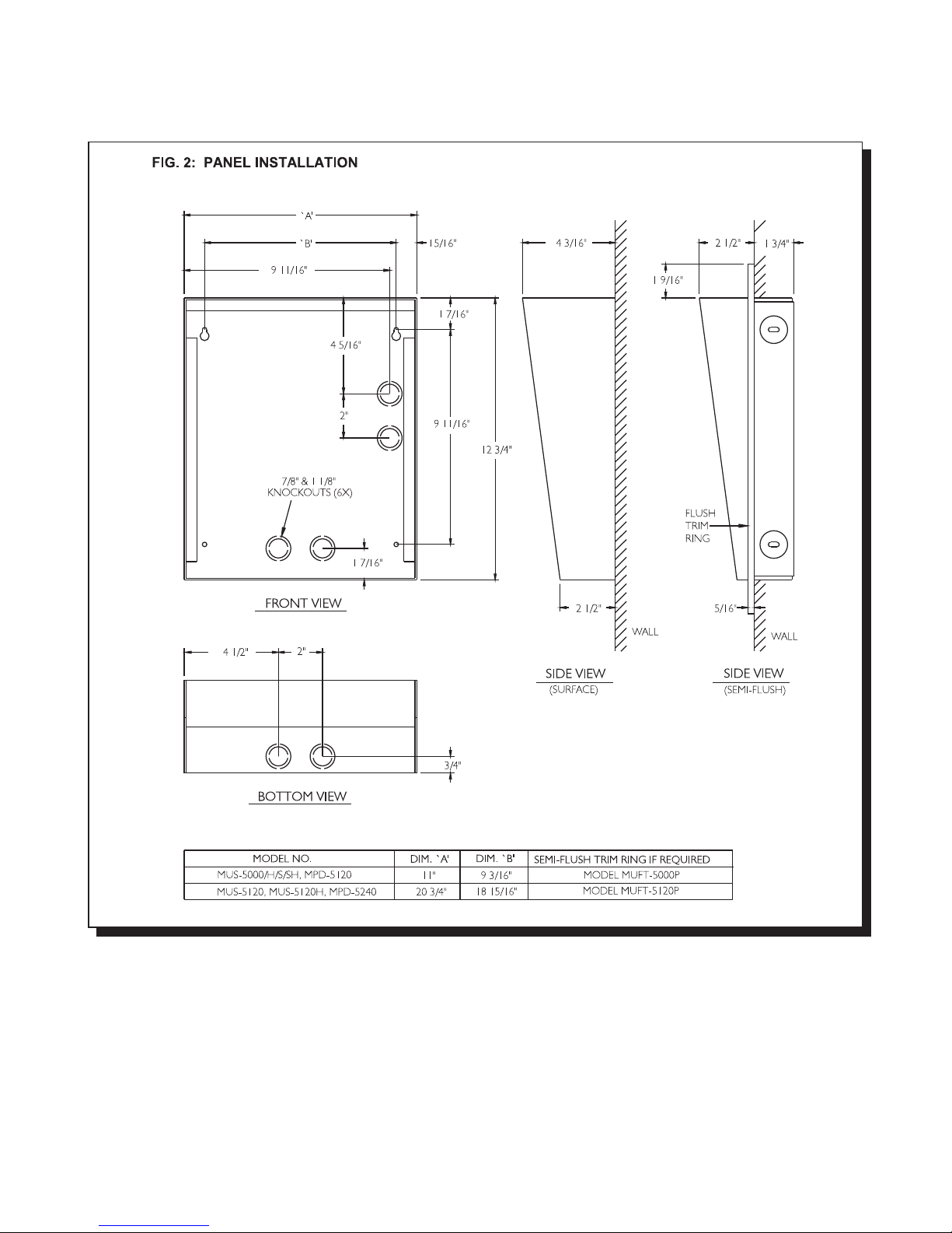
MOU NTING TH E UN IVERSAL TYPE LOBBY/ENTRY PANEL
Mount the panel as shown on FIG.1 and FIG.2 using the supplied screws.
MIRCOM TECHNOLOGIES LIMITED, 9500 Series: No Subscriber Line Page 12
MOUNTING THE M AGNETIC LETTER KIT MODEL MLK-040 (OPTIONAL)
Mount the Magnetic Letter Kit according to the Installation Instruction that comes with the Kit. Extra characters and
mag ne tic strips can be ordered se pa rately. Please contact the factory or our nearest dealer.
MIRCOM TECHNOLOGIES LIMITED, 9500 Series: No Subscriber Line Page 13
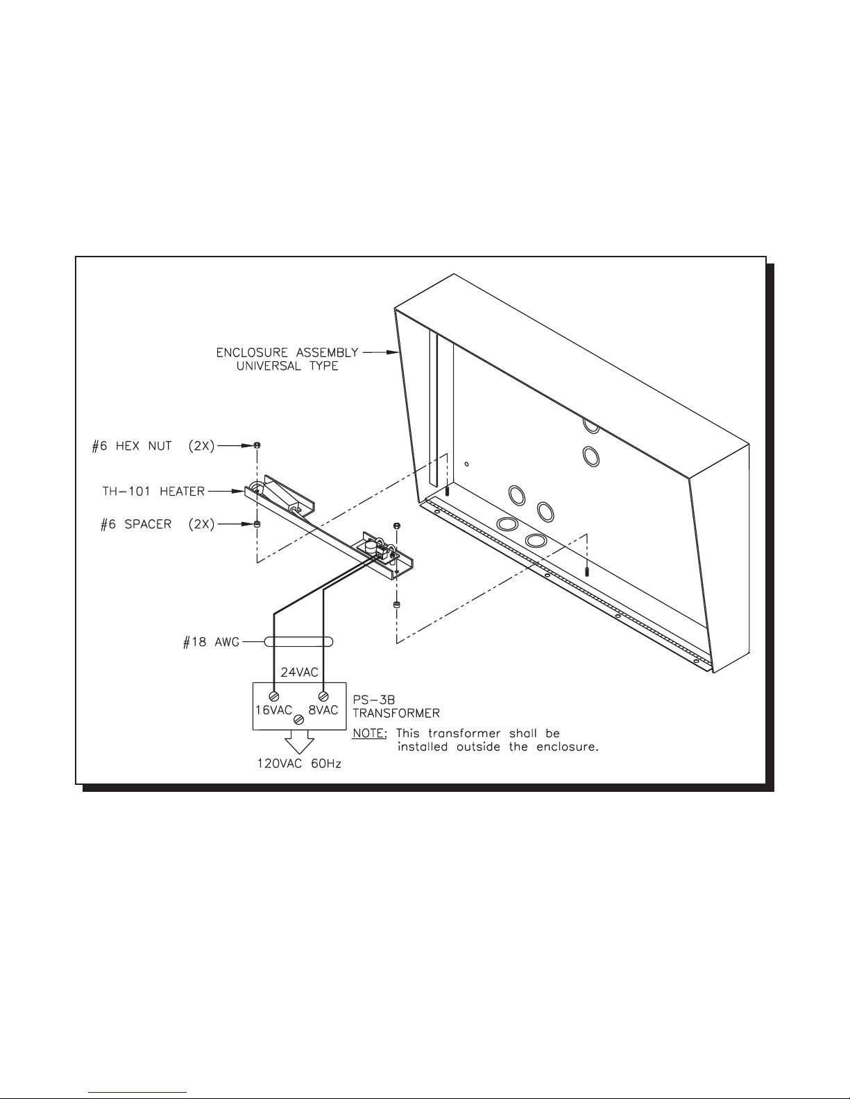
MOUNTING THE THERM O STAT HEATER KIT MODEL TH-101 (OPTIONAL)
Mount the Heater Kit according to Fig 2A . Install the TH-101 Heater into bottom left hand corner of the universal
enclosure using the two spacers and two hex nuts provided. Use a pair of #18 AW G wires to connect from the
TH -1 0 1 u n it to 24 V A C ta p o n the P S -3 B tran s fo rmer. T h e tran s fo rmer mus t b e in sta lled o u tsid e th e en c los ure .
Fig. 2A: HEATER INSTALLATION
MOU NTING TH E CO NT INENTAL TYPE LOBB Y/ENTRY PANEL
MIRCOM TECHNOLOGIES LIMITED, 9500 Series: No Subscriber Line Page 14
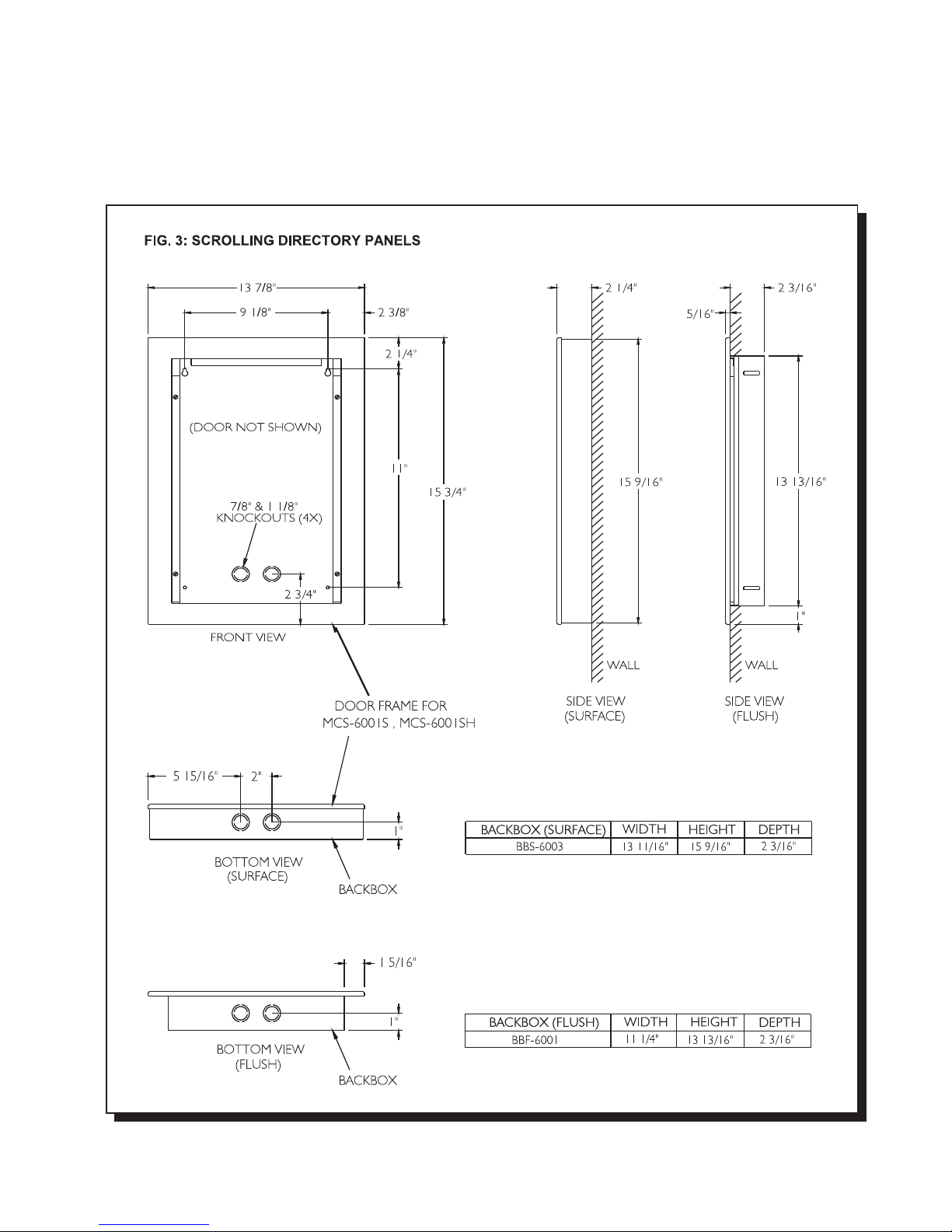
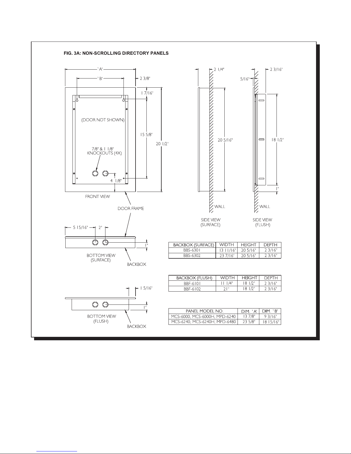
Mount the panels as shown on FIG.3 (for scrolling) or FIG.3A (for non-scrolling) using the supplied screws.
MIRCOM TECHNOLOGIES LIMITED, 9500 Series: No Subscriber Line Page 15
MOUNTING THE M AGNETIC LETTER KIT MLK-070 (OPTIONAL)
Mo unt th e Mag n e tic Le tter Kit acc o r d in g to th e Insta lla tio n Instructio n th at co me s w ith the K it. T h is kit is u s e d on ly
for C on tine n tal type lobb y/en try pa n el.
MIRCOM TECHNOLOGIES LIMITED, 9500 Series: No Subscriber Line Page 16
MOU NTING TH E DEC ODER/RELAY CABINET
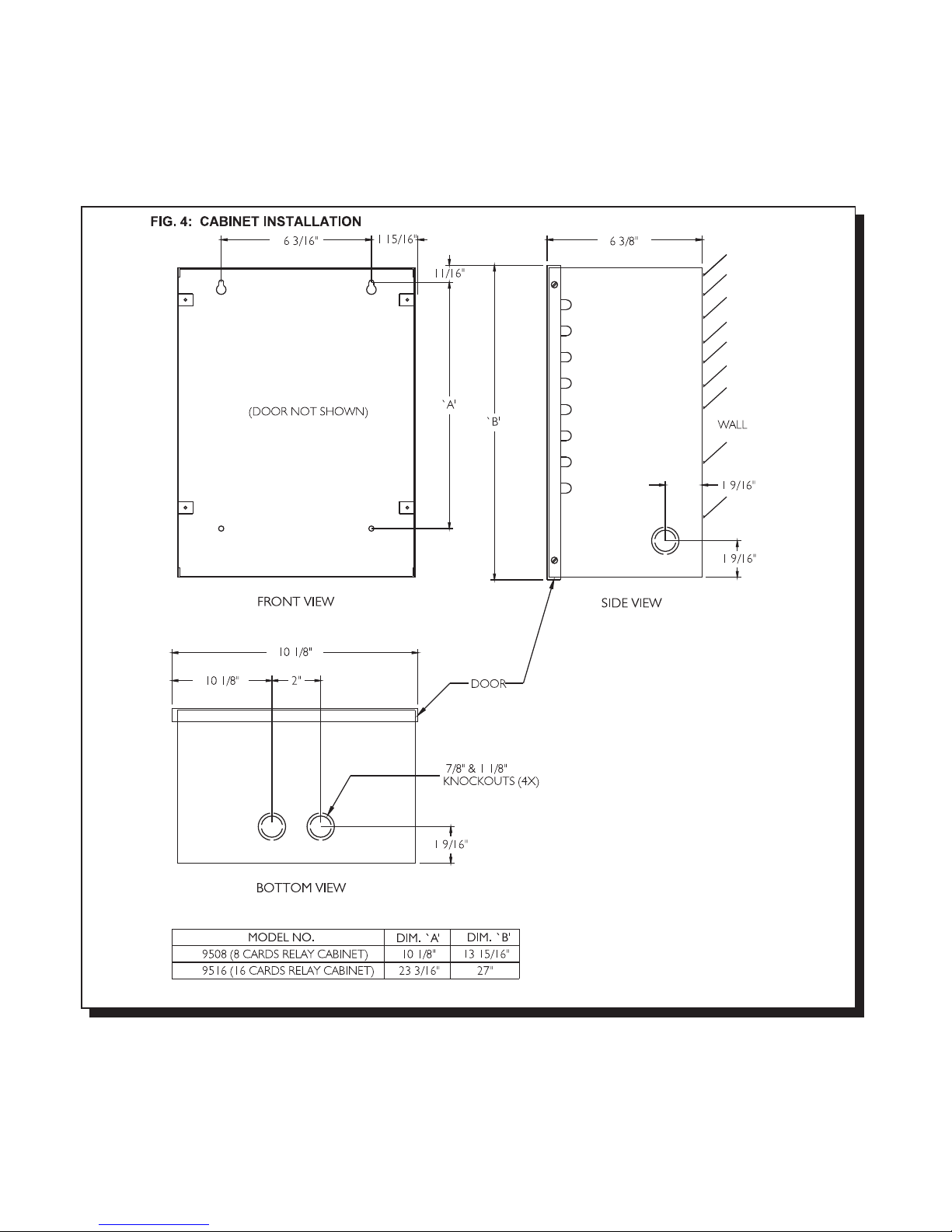
Mount the Decoder/Relay Cabinet as shown on FIG. 4 using the supplied screws.
MIRCOM TECHNOLOGIES LIMITED, 9500 Series: No Subscriber Line Page 17

ELECTRONIC MODULES INSTALLATION INSTRUCTIONS
MOUNTING THE 9501A, 9502A, or 9503 CONTROLLERS
Mount the controllers according to their respective installation instructions and follow the precautions mentioned on the
package. It is import ant to note that these modules are sensitive to electrostatic di scharge and must be handl ed properly. To
avoid static discharge, we recommend touching a metallic object before opening the packages and handling these modules.
These Controllers can be mounted on either Universal or Continental type lobby/entry panels.
MOUNTING THE MD-345 (Aux. Relay Board)
Mount the board as shown on the installation instructions that come with the module.
RELAY CARDS MODEL 9512 INSTALLATION
Install the relay cards by matching the polarizing plastic peg and the keyhole on the decoder/mother board. No configuration
or jumper setting is required. All plugged-in relay cards are recognized automatically by the system. Connect the 6 ft.
Amphenol Cables models 9106 (standard), 9106E (interface to existing RJ-71A BIX Blocks), 9106BC or 9406 (octopus) to
the relay cards and tighten the screw(s) to secure the cables to the plates.
SYSTEM WIRING INSTRUCTIONS
WIRING THE 9501A (Main Controller) TO 9508 or 9516 (Relay Cabinets)
Note that the Relay Control wiring (Data, Clock, Latch, Gnd) needs to be shielded 4-wire 22AWG cable. The shields must be
connected to Earth Ground at each terminating point. Also note that the Relay Control line “COM(-)” (marked “GND” on some
older boards) is a system “Common” and MUST NOT be connected to Earth Ground !
FIG.5 COMMUNICATION LINK WIRING
MIRCOM TECHNOLOGIES LIMITED, 9500 Series: No Subscriber Line Page 18
 Loading...