

Mircom MCS-6001SV, MCS-6000H, MCS-6240, MCS-6240H, MCS-6001SHV Installation, Programming, And Troubleshooting Manual
...Page 1
®
9500 Series
NSL No Subscriber Line Access Systems
Scrollin g & N o n -S cro llin g D ire cto ry
INSTALLATION, PROGRAMMING,
and TROUBLESHOOTING MANUAL
L NOTICE
All information, documentation, and specifications contained in this manual are subject to change
without prior notice by the man ufa cturer.
©1998 by Mircom Technologies Limited
Printed in CANADA, June 30, 1998
LT-4 6 2 re v.6
Page 2

TABLE of CONTENTS
IMPORTANT NOTICE 1
SYSTEM FEATURES 2
IN TR ODU C TION 3
SPECI FICATI ONS 3
OPERATION 3
SYSTEM BLOCK DIAGRAM:
Single Entrance Application 5
Multiple Entrances Application 6
Multiple Building Application 7
PRE-INSTALLATION PLANNING:
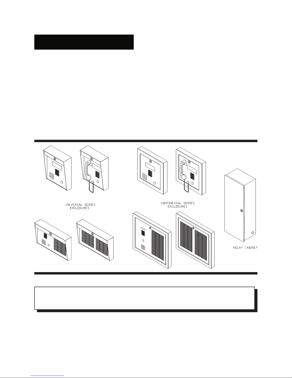
Entry or Lobby Panel Types 8
Controllers 9
Op tiona l P ro gra mming S oftw a re K it (us ing IB M PC), Mode l R S -4 8 5IM 9
Decoder/Relay Cabinets 10
Site Selection 10
Power Supply Requirements 10
W iring Requirements 10
CA-71A BIX Block or RJ-71C Punch-down Block Wiring Configuration 11
Door Strikes 11
Post Office Lock 11
ENCLOSURES AND ACC ESSO RIES INSTALLATION INSTRUCTIONS:
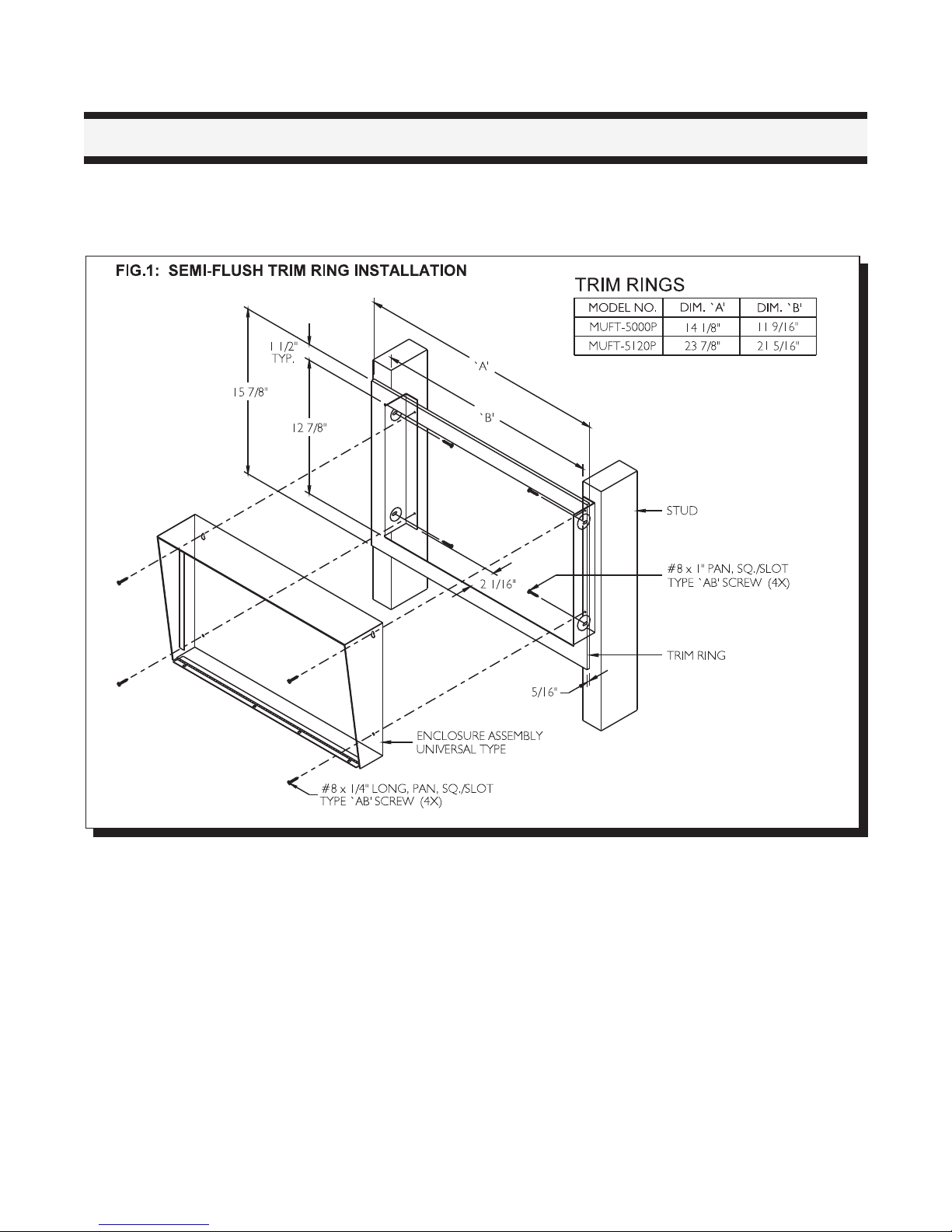
Semi-Flush Trim Ring Installation 12
Mounting the UNIVERSAL Type Lobby/Entry Panels 13
Mounting the Magnetic Letter Kit (MLK-040) 13
Mounting the Thermostat Heater Kit Model TH-101 14
Mounting the CONTINENT AL T ype Lobby/Entry Panels 15
Mounting the Magnetic Letter Kit (MLK-070) 16
Mounting the Decoder/Relay Cabinet 17
ELECTRONIC MOD ULES INSTALLATION INSTRUCTIONS:
Mounting the 9501A, 9502A or 9503 Controllers 18
Mounting the MD-345 Auxiliary Relay Board 18
Relay Cards Model 9512 Installation 18
SYSTEM WIRING INSTRUCTIONS:
W iring the 9501A (Main Controller) to 9508 or 9516 (Relay Cabinets) 18
Relay Cabinet's Decoder/Mother Board Jumper Configuration 19
W iring the Door Strike 19
W iring the Electromagnetic Door Lock 20
W iring the Lock-Back Switch 20
W iring the Door Override (Postal Lock & Fire Alarm) 21
W iring the Music Source to 9501A Controller 21
W iring the Auxiliary Relay and Main Entrance Active Relay Contacts 22
W iring the System and Lamp Supplies 22
W iring Instruction for Multiple Entrances Application 23
W iring the Guard Telephone to 9501A Controller 23
W iring the Speaker, Mic., and Keypad/Display Assembly 24
W iring to Earth Ground 24
W iring the Dedicated Telephone Line (Outside Line) 24
POWERING TH E SYST EM 24
®
Page 3

ELEVATOR REC ALL (REST R ICTION) FEAT UR E 25
PROG RAM M ING INST RU CT IONS: Scrolling Dir. Non-Scrolling
Entering Programming Mode . . . . . . . 28 40
Direct Access Programming Codes Table . . . . 29 41
"No Manual" Menu Driven Programm ing Using *888 . . . 30 41
Manual Entry of Residents’/Tenants’ Dial Codes and Relay # . 30 42
Entry, Review, Edit or Delete Dial Codes or
Residents’/Tenants’ Names . . . . . . . . . . 31 42
Auto Programming the Residents’ Dial Codes . . . . 32 43
Programming the Keyless Entry Codes . . . . . . 32 43
Review and Delete Keyless Entry Codes . . . . . 33 44
Reprogramming Master Code . . . . . . . 33 44
Set Door Timer . . . . . . . . . . . . 34 45
Elevator Recall . . . . . . . . . . . . 35 45
Set On-Line Timer . . . . . . . . . . . 35 45
Multiple/Single Entrance Select . . . . . . . . 35 46
Ring Cycle Select . . . . . . . . . . . 36 46
Set Clock............. 37 47
Two 11-digit Telephone Number Entry . . . . . . 37 47
Ring Pattern Select . . . . . . . . . . . 38 47
Sort Residents' Names . . . . . . . . . . 38 --
Select Digit for Hold . . . . . . . . . . 39 48
MASTER CODE RESET ................40
REPLACEMENT:
Lamp Replacement (Universal type lobby panels only) . . . . . . 22
Fuses Replacement . . . . . . . . . . . . . 39
SYSTEM ADJUSTMENT S:
Music Level Adjust . . . . . . . . . . . . . . . 49
Microphone Volume . . . . . . . . . . . . . . 49
Speaker Volume............... 49
Pulse Sensitivity Adjust . . . . . . . . . . . . . . 49
Display Contrast Adjustment . . . . . . . . . . . 50
TROUBLESHOOTING.................51
APPENDICES:
A-1: CA-71A BIX Block W iring configuration . . . . . . . . 52
A-2: RJ-71C Punch Down Block W iring Configuration . . . . . . 53
B-1: CA-71A BIX Block Identification Form . . . . . . . . 54
B-2: RJ-71C Punch Down Block Identification Form . . . . . . 55
C: Accessory Specifications . . . . . . . . . . . . 56
D-1 and D-2: Directory Worksheets . . . . . . . . . . 57,58
E: Character Set Table . . . . . . . . . . . . . . 59
RESIDENT O PER AT ING INSTR UC T IONS . . . . . . . . . . . . 60
WARRANTY.................. .61
Page 4

IMPORTANT NOTICE
Notice for all 9500 series Telephone Entry Systems Sold in Canada:
The Canadian Department of Communications label identifies certified equipment. This certification means that the equipment
meets certain telecommunications network protective, operational and safety requirements. The Department does not
guarantee the equipment will operate to the user's satisfaction.
Before installing this equipment, users should ensure that it is permissible to be connected to the facilities of the local
telecommunication company. The equipment must also be installed using an acceptable method of connection. The customer
should be aware that compliance with the above conditions may not prevent degradations of service in some situations.
Repairs to certified equipment should be made by an authorized Canadian maintenance facility designated by the supplier.
Any repairs or alteration made by the user to this equipment, or equipment malfunctions, may give the telecommunications
company cause to request the user to disconnect the equipment.
Users should ensure for their own protection that the Earth Ground connections of the power utility, telephone lines and
internal metallic water pipe system, if present, are connected together. This is necessary both for proper operation and for
protection.
CAUTION: Us e rs sh o uld no t atte mpt to m a k e s u ch c o nn e c tions the mselv es , b ut s h ou ld c o nta c t the ap p ro pria te
electric inspection authority, or electrician, as appropriate.
NOTICE:
The LOAD NUMBER (LN) assigned to each terminal device denotes the percentage of the total load to be connected to a
telephone loop which is used by the device, to prevent overloading. The termination on a loop may consist of any
combination of devices subject only to the requirement that the sum of the load numbers of all devices does not exceed
100.
INDUSTRY CANADA (Formerly D.O.C.) Registration Number: 1156 6200 A
Notice for all 9500 series Telephone Entry Systems Sold in the U.S.A.:
This equipment has been tested and found to comply with the limits for a class A digital device, pursuant to Part 15 of the
FCC Rules. These limits are designed to provide reasonable protection against harmful interference when the equipment
is operated in a commercial environment. This equipment generates, uses, and can radiate radio frequency energy and,
if not installed and used in accordance with the instruction manual, may cause harmful interference to radio
communications. Operation of this equipment in a residential area is likely to cause harmful interference in which case
the user will be required to correct the interference at his own expense.
WARNING:
Changes or Modifications not expressly approved by MIRCOM TECH NO LO G IES LTD. could void the users’
autho rity to op e ra te th e e q uip ment.
F.C.C. Registration Number: 1M8CAN-21269-D T-E
Notice for all 9500 series Telephone Entry System Sold Internationally:
Conformity to the local Tel. Co. standards must be reviewed before installation of 9500 Series Telephone
Access Systems.
MIRCOM TECHNOLOGIES LIMITED, 9500 Series: No Subscriber Line Page 1
Page 5

SYSTEM FEATURES
SCROLLING DIRECTORY FEATURES: NON-SCROLLING DIRECTORY FEATURES:
T SCROLLING DIRECTORY T Capacity for up to 1000 Suites or Telephone Lines.
T Programmable using the lobby panel’s keypad T Programmable using the lobby panel’s keypad
T 15 Characters Resident Name length. for Residents plus five (5) spares for use of
T Capacity for up to 1000 Suites or Telephone Lines. building management.
T 1000 reprogrammable KEYLESS ENTRY codes TSUPERTWIST 2 lines by 16 characters backlit
T 4 lines by 20 characters VFD (Vacuum Fluoresc ent Dis play)
COMMON FEATURES FOR BOTH SCROLLING AND NON-SCROLLING TEL. ACCESS SYSTEMS:
T No SUBSCRIBER PHONE LINE FEE is required.
T User programmable MASTER CODE for sec urity
T Capability of rotary "PULSE" or touch tone "DTMF" dialling.
T VARIABLE RESIDENT CODE LENGTH, 1, 2, 3 or 4 digit.
T SINGLE or MULTIPLE ENTRANCES capabil ity.
T DOOR OVERRIDE connection for fire alarm. Doors will
T Built-in POST OFFICE LOCK micro switch.
T Connection for "LOCK-BACK" door contact to lock door
T MAIN ENTRANCE ACTIVE RELAY CONTACTS for use
T AUXILIARY RELAY CONTACTS for use of auxiliary
T User Definable Start Number for auto-programming
T Programmable "DOOR OPEN" timer (99 seconds max.).
T Programmable "ON LINE or CONVERSATION TIME"
T Adjustable number of RING CYCLES.
T Built-in CALL WAITING feature.
T MUSIC-ON-HOLD input for music source (mono) such
TNONVOLATILE MEMORY (EEPROM), retains programmed
T GUARD or CONCIERGE telephone connection. Use for
T DEDICATED TELEPHONE LINE, allows to dial 2 telephone
T Stainless Steel or Painted Vein (textured) lobby panels
(Universal or Continental type enclosures).
T Watch Dog Timer circuit to automatically reset the unit to
T Compact, small, and easy to install Decoder/Relay Cabinets
®
or IBM PC T 1000 reprogrammable KEYLESS ENTRY codes
for Residents plus five (5) spares for use of extended temperature LCD display.
building management.
and programming access.
pulse open during emergency.
as soon as it is open to prevent "tailgating" through.
of camera activation.
entrance or garage door.
the Residents’ access codes.
timer (99 seconds max.).
as radio or tape deck.
information during power failure.
calling the Residents or Suites.
numbers of up to 11 digits.
eliminate system latch-up.
with LED indicator for each phone line. Ideal for installers
and troubleshooting.
MIRCOM TECHNOLOGIES LIMITED, 9500 Series: No Subscriber Line Page 2
Page 6

INTRODUCTION
MIR C OM 'S 9 5 00 S e ries E ntry S yste ms p ro vide s a h igh qu a lity two wa y co mmunic atio n b e twe e n the res id en ts
and their visitors in a multi-unit dwelling establishment. The system uses the existing phone lines for
comm unication and access control. The system does not require a subscriber phone line since it uses the existing
phone line wiring. No expensive installation costs are incurred compared to traditional hardwired intercom
systems. Its versatile design is loaded with standard features such as call waiting, metal keypad, multiple entrance
ca p a b ility, a n d p r o v is io n f o r p osta l lo c k. T h e s ys tem lo b by pan els a re a v a ila b le in h e avy ga uge n o n ma g n e tic
stainless steel or painted vein (textured) finish. Surface or Flush mount applications are available by selecting the
appropriate enclosure type (Universal or Continental, see page 7). Installation is quick and easy featuring a low
voltage operation and complete system programmability using the lobby panel’s keypad or IBM PC .
† Trademark of International Business Machine personal computer
® †
SPECIFICATIONS
The operating temperature range is 50 °C (122 °F) to -20 °C (-4 °F). It is necessary that an optional TH-101
Thermostat Heater be installed when the ambient temperature falls below 0 °C (32 °F)
Power Supply Voltage Range is 105 to 128 VAC.
Us e L o op S ta r t p h o n es o n ly (n o t Gro u n d Sta r t p h o n e s ), ch e c k with you r lo c a l telep h o n e c o mp a n y.
OPERATION
STANDARD OPERATION FOR SCRO LLING DIRECTO RY UN ITS:
Visitor calling the Res iden t:
At th e e n tr y p o in t ( lo b b y) , th e v is itor loc a tes th e Res id e n t’s Dial Code and Name by scrolling through the directory
list displayed on the screen by using the * or # keys. Pressing the * or # key mom entarily will scroll the list "up or
down" one name at a time. Holding the * or # key will scroll the list "up or down" continuously and stop scrolling
when the key is released. A known Dial Code can b e e n te r e d d ir e c tly o n keyp a d w ith o ut sc r o llin g . When a c a ll is
placed, a distinguishable ring notifies the resident that a visitor is calling. While talking to the visitor, the resident
m a y d ia l "9" to o p e n the ma in d o o r o r h a n g - u p th e ph o n e to r e fuse e n tr y.
STANDARD OPERATION FOR NON -SCROLLING DIRECTO RY UNITS:
Visitor calling the Res iden t:
At the entry point (lobby), the visitors locates the Resident’s Dial Code on the direc tory a nd e nte rs the a pp ro p riate
code number on keypad. When a call is placed, a distinguishable ring notifies the resident that a visitor is calling.
Wh ile ta lk in g to th e v is ito r , th e r e s id e n t ma y d ial "9" to op e n th e ma in d o o r o r h ang -u p the p h o n e to ref u s e e n tr y.
NOTE: Residents’ telephones must be capable of generating a touch tone (DTMF) or rotary "PULSE" signal for
the digit "9" for the door release circuit to activate.
OPERATION FOR AUXILIARY RELAY OUTPUT:
If the auxiliary relay output is used for control of garage or dock doors, the resident can activate or release the
auxiliary door by pressing the number "6". This function is available by using a touch tone (DTMF) type
tel ephones. No provision for Pulse (rotary) type telephones.
OPERATION FOR GUARD or CON CIERGE LINE:
The Guard can call the residents or suites by simply dialling * key followed by the resident's Dial Code . Also, the
MIRCOM TECHNOLOGIES LIMITED, 9500 Series: No Subscriber Line Page 3
Page 7

Guard can release the door by pressing the # key to a llo w en try. This function is available by using a touch tone
(DTMF) type telephones. No provision for Pulse (rotary) type telephones.
Call Waiting Feature:
All 9500 S e ries s yste ms ha s a b u ilt-in two -w ay c all wa iting fe a tu re th a t no tifies the res id en t (u sin g th e ph o ne ) w ith
a distinct tone that an incoming caller is waiting. The resident may answer the call by flashing the hook switch.
There are two possible scenarios or situation exists here and are described below.
1. Th e vis ito rs p lac e d a c a ll w h ile th e re s id en t is o n th e p h o n e (c o n ve rs in g with o u ts id e p a rty ):
In this situation, the resident will hear a distinct tone meaning that a visitor is calling from the lobby. The resident
can answer the call by simply flashing the hook switch. This action will automatically put the outside party “on
hold”. While talking to th e visitors , th e re s ide n t ca n allow e ntry b y dialling th e d igit "9" to o p en the main d o or o r to
refus e en try simply flash th e h o ok s w itch o r dia l digit “4". Either action will reconnect the resident to the outside
party (pre vio us ly pu t “on h old ”) to co n tinue th eir c o nv ers a tion .
2. The resident received an outside call while talking to the visitors in the lobby:
In this situation, the resident will hear a distinct tone meaning that an outside line caller is waiting. There are two
ways to an s w e r this ca ll. On e is to ha n g u p the ph o ne b y simply flash ing the ho o k s w itch or d ial the d igit “4"
(refus ing e ntry). T h e s ec o n d is b y dialling th e digit "9" w h ic h w o u ld a llo w en tr y. B o th ac tio n s will automatic a lly
con ne c t the re sid en t to th e ou ts ide line. P lea se n ote tha t the re sid en t cannot put the visitors on hold because
of the a llow ab le ta lk -time lim it of the s yste m.
MIRCOM TECHNOLOGIES LIMITED, 9500 Series: No Subscriber Line Page 4
Page 8
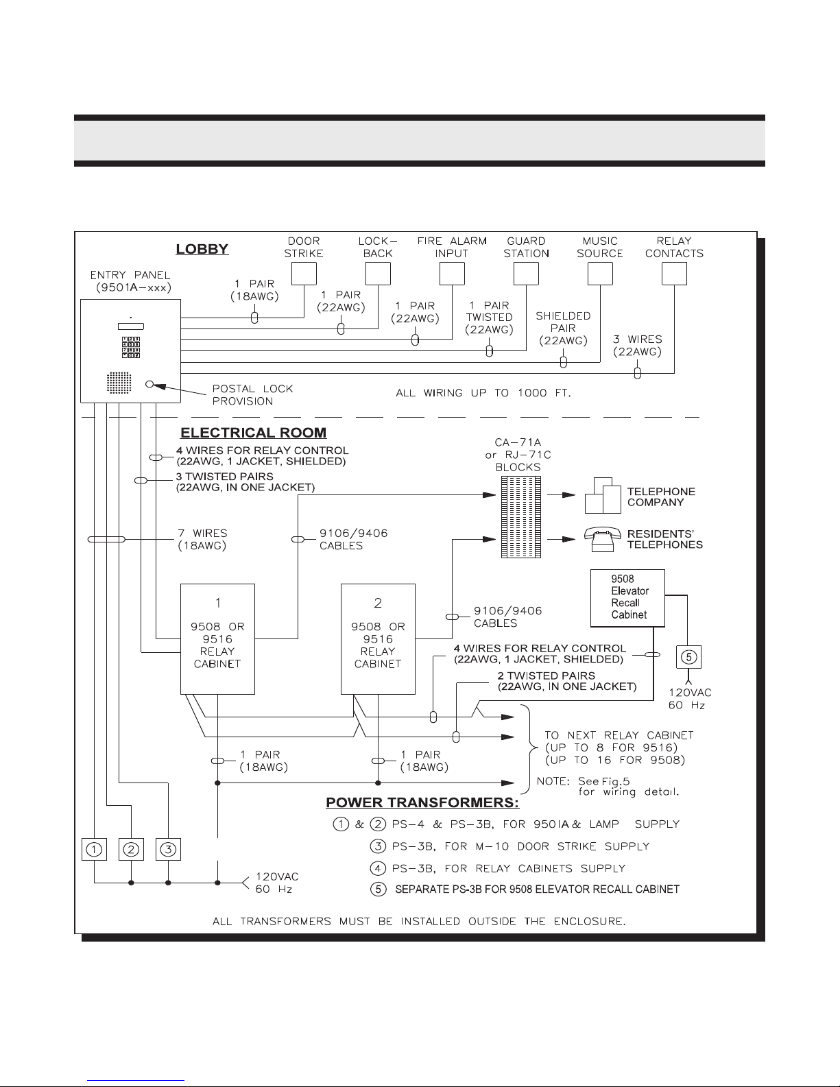
SYSTEM BLOCK DIAGRAMS
SINGLE ENTRANCE APPLICATION:
MIRCOM TECHNOLOGIES LIMITED, 9500 Series: No Subscriber Line Page 5
Page 9
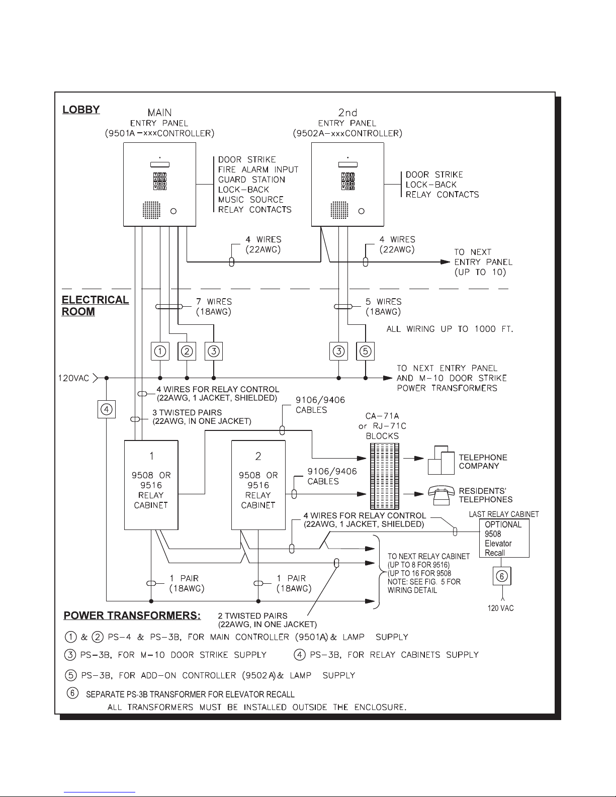
MULTIPLE ENTRANCES APPLICATION:
MIRCOM TECHNOLOGIES LIMITED, 9500 Series: No Subscriber Line Page 6
Page 10
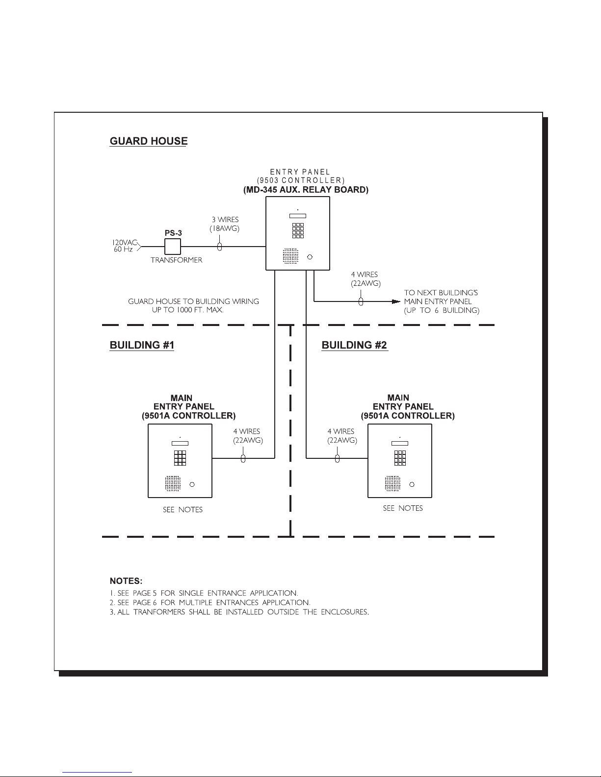
MULTIPLE BUILDING APPLICATION:
MIRCOM TECHNOLOGIES LIMITED, 9500 Series: No Subscriber Line Page 7
Page 11

PRE-INSTALLATION PLANNING
Before the actual installation begins, the system requires various items to be pre-arranged and are described
below :
1. ENTRY OR LOBBY PANEL TYPES
The UNIVERSAL series entry/lobby panels are hooded surface mount enclosures with built-in lighting for outdoor
or in d o o r a p p lic a tions . Optio nal flu s h tr im rin g s are a v a ila b le f o r s e mi-f lu s h in s tallatio n s . The r e a r e s ix (6) mod e ls
available and are listed below:
Universal Panels for Scrolling Directory:
Model MUS-5000SV ± S ta in less S teel fin is h e n tr y p a nel co me s with keyp a d , 4 x 2 0 VF D dis p la y,
micropho ne , speak er, and micro switch for postal lock. No controller.
Model MUS-5000SHV ± Stain le s s S teel fin is h en try p ane l c o me s w ith keyp a d , 4 x20 V F D dis p la y,
armou red ha nd set, and micro switch for postal lock. No controller.
Universal Panels for Non-Scrolling Directory:
Model M US-5000 ± Stainles s S teel fin is h e n tr y p a nel com e s with keyp a d , 2 x 16 L C D dis p la y,
microphone, speaker, and micro switch for postal lock. No directory and
controller.
Model M US-5000H ± Stainles s S te e l finish en try pa n el co mes w ith k e ypa d, 2 x 16 L C D d isp lay, ha n ds e t,
and m icro sw itch for postal lock. No directory and controller.
Model M US-5120 ± Stainles s S teel fin is h e n tr y p a nel com e s with keyp a d , 2 x 16 L C D dis p la y,
microphone, speaker, micro switch for postal lock, and paper directory for 120
names . N o c o ntro ller.
Model M US-5120H ± Sta in le s s Ste e l f in is h e n tr y p a n e l c o me s with k e ypad , 2 x 1 6 L CD dis p la y,
handset, micro switch for postal lock and paper directory for 120 names. No
controller.
Accessories:
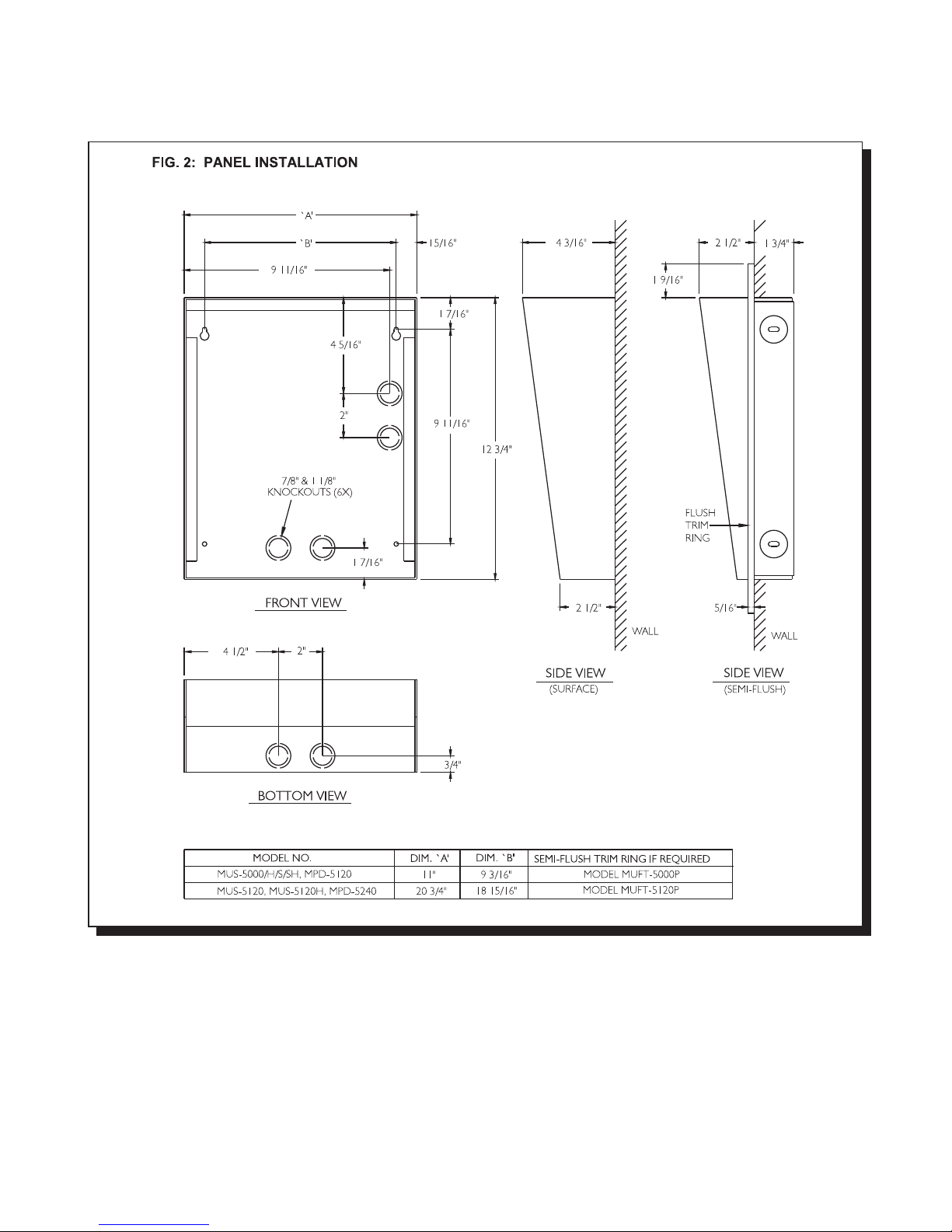
Model MUFT -5000P ± Flush trim ring for MU S -5000 /H/S/SH pa nels.Painted black (textured).
Model M UFT -5120P ± Flush trim ring for M U S-51 20/H , and M P D -5240 pane ls. Painted black (textured).
M od el MPD -5120 ± Stain le s s S teel a d d - o n p a p e r d ire c tory pa nel, 1 2 0 n a me s c a p a city.
Model M PD -5240 ± Stain le s s S teel a d d -on p a p e r d ir e c tory pa n e l, 240 n a me s c a p a c ity.
Model M LK -040 ± Magn e tic s trips dire c tory k it, 40 na mes ca p a city. It comes w ith p las tic letters,
magnetic strips, brackets, and hexnuts.
Model TH-101 ± Therm os tat heater.
Note: P ainted Silver, Gold & C oppe r Ve in lobby pane ls are available by custom orde r.
MIRCOM TECHNOLOGIES LIMITED, 9500 Series: No Subscriber Line Page 8
Page 12

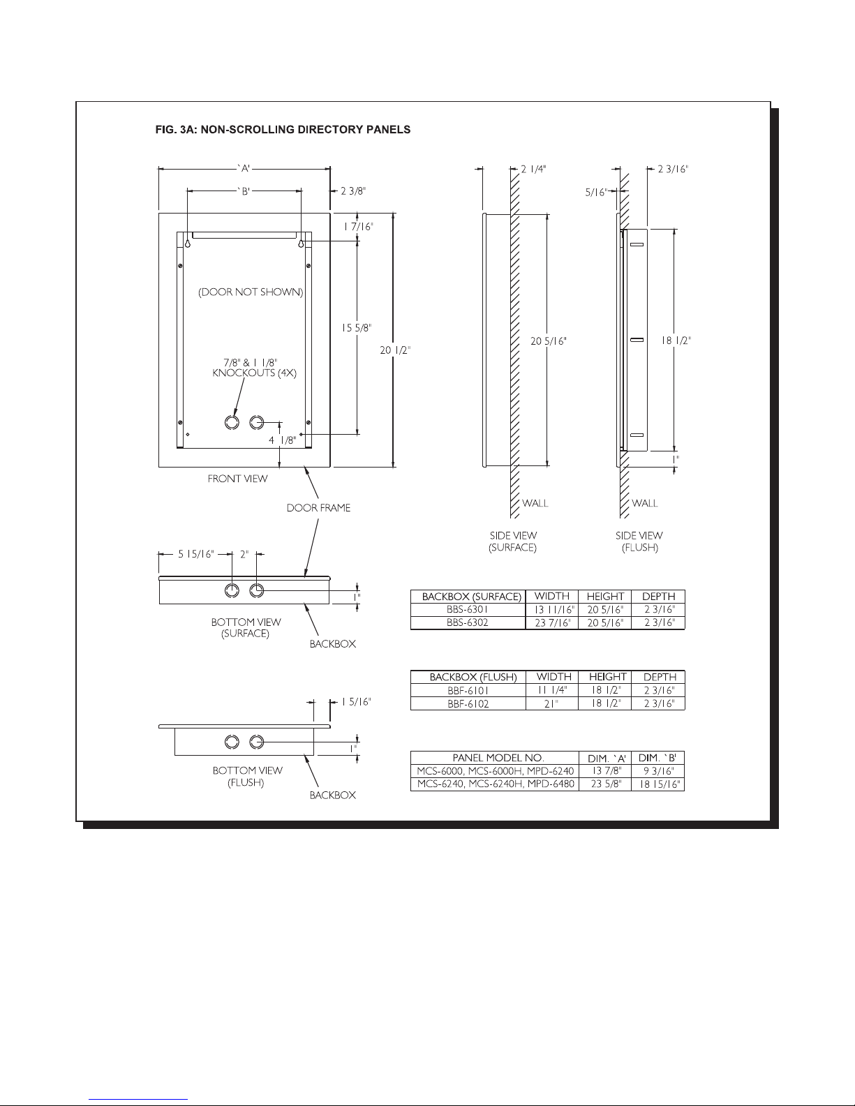
The CONTINENTAL series entry/lobby panels are designed for indoor applications only. These elegant lobby
panels c a n b e mo u n te d e ither f lu s h o r s u r fa ce b y s e le c tin g the a p p ropria te ba c kbo x . The r e a re six (6 ) mo d e ls
available and are listed below:
Continental Panels for Scrolling Directory:
Model MCS-6001SV ± S ta in less S teel fin is h e n tr y p a nel co me s with keyp a d , 4 x 2 0 VF D dis play,
micropho ne , speak er, and micro switch for postal lock. No controller.
Model MCS-6001SHV ± Stain le s s S teel fin is h en try p ane l c o me s w ith keyp a d , 4 x20 V F D dis p la y,
armou red ha nd set, and micro switch for postal lock. No controller.
Continental Panels for Non-Scrolling Directory:
Model M CS-6000 ± Stainles s S teel fin is h e n tr y p a nel com e s with keyp a d , 2 x 16 L C D dis p la y,
microphone, speaker, and micro switch for postal lock. No directory and
controller.
Model M CS-6000H ± Stainles s S te e l finish en try pa n el co mes w ith k e ypa d, 2 x 16 L C D d isp lay, ha n ds e t,
and m icro sw itch for postal lock. No directory and controller.
Model M CS-6240 ± Stainles s S te e l finish en try pa n el co mes w ith k e ypa d, L C D d isp lay,
microphone, speaker, micro switch for postal lock, and paper directory for 240
names . N o c o ntro ller.
Model M CS-6240H ± Stainle ss S te el finis h e n try pa ne l co mes with k eyp ad , L C D d isp lay,
handset, micro switch for postal lock and paper directory for 240 names. No
controller.
Accessories:
Model MPD-6240 ± Add -o n pa p e r d ir e c tory pa n e l, 240 n a me s c a p a city.
Model M PD -6480 ± Add- o n p a p e r d ir e c to r y p a n e l, 4 8 0 na me s c a p a c ity.
Model BBF-6001 ± Flush b a ckbox fo r M CS-6 00 1 S /S H . S atin co a t finish .
Model BBS-6003 ± Surface b ack bo x for M C S -6001 S/SH . Painted black (textured).
Model BBF-6101 ± Flush backbox for MCS-6000, MCS-6000H, and MPD-6120 panels.
Model BBF-6102 ± Flush backbox for MCS-6240, MCS-6240H, and MPD-6480 panels.
Model BBS-6301 ± Surf a ce b a ckbox fo r M CS-60 0 0 , M C S -6 0 0 0H, and M P D -6 2 4 0.
Model BBS-6302 ± Surf a ce b a ckbox fo r M CS-62 4 0 , M C S -6 2 4 0H, and M P D -6 4 8 0 p a ne ls .
Model M LK -070 ± Magn e tic s trip d irec to ry kit, 70 n ames c a pa c ity. It comes w ith p las tic lette rs ,
magnetic strips, brackets, and hexnuts.
Note: Painted Silver, Gold & Copper Ve in lobby pane ls are available by cus tom order.
2. CONTROLLERS
SCROLL ING D IRECT O RY CO N TR O LLER S: For both LCD and VFD Display
Mo d e l 950 1-0 40 A ± M a in Con tr o lle r . 4 0 n a me s c apa c ity.
Mo d e l 950 1-1 20 A ± M a in Con tr o lle r . 1 2 0 n a me s cap a c ity.
Mo d e l 950 1-3 60 A ± M a in Con tr o lle r . 3 6 0 n a me s cap a c ity.
Mo d e l 950 1-8 00 A ± M a in Con tr o lle r . 8 0 0 n a me s cap a c ity.
Model 9502-040A ± A d d - o n Con tr o lle r f o r a u x ilia ry e n tr a n ce(s ) . 4 0 n am e s ca p a c ity.
Model 9502-120A ± A d d - o n Con tr o lle r f o r a u x ilia ry e n tr a n ce(s ) . 1 2 0 na mes ca p a c ity.
Model 9502-360A ± A d d - o n Con tr o lle r f o r a u x ilia ry e n tr a n ce(s ) . 3 6 0 na mes ca p a c ity.
Model 9502-800A ± A d d - o n Con tr o lle r f o r a u x ilia ry e n tr a n ce(s ) . 8 0 0 na mes ca p a c ity.
Note: M ake sure to order the proper lobby panels meant for scrolling directory.
Option al Prog ramming So ftw are Kit:
Model RS-485IM Interface Module, along with MSW-001 MirSoft TAS programming software, is an optional
programming kit to enable the user to upload or download residents’ names, dial codes, keyless entry codes,
and relay line numbers using a personal computer. This software can be used on IBM
PC /X T /2 8 6/3 8 6/4 8 6/P e n tium Co mpa tible P C u nd e r M S -DO S version 5 or h ig he r, Window s 9 5 or higher, OS/2
with Colour or Monochrome Text Screen (MDA, CGA, EGA, VGA, SVGA) capability and one serial port. To order
this kit, please consult our factory for further information.
®®®
®
MIRCOM TECHNOLOGIES LIMITED, 9500 Series: No Subscriber Line Page 9
Page 13

NON -S C R O L LIN G D IRE C T O R Y C O N T R O L LE R S :
Mo d e l 950 1A ± Ma in C o n troller.1 0 00 re s ide nts c ap a c ity.
Model 9502A ± Add - o n Con tr o lle r f o r a u x ilia r y en tr a n ce(s). 10 00 re s id ents c a p acity.
Model 9503 ± Multi- B u ild ing Gua rd Hou s e Con tr o lle r . 1 0 0 0 r e s id e n ts ca p a c ity.
Accessory:
PCB Assy.: MD-345 ± Auxiliary 6 relay board. This module is intended for use of Multiple Building
Application or for applications where relay contacts are required for activation of
peripherals. Please contact our Engineering Field Support Personnel for detailed
wiring scheme and information.
Note: Make sure to order the proper lobby panels meant for non-scrolling directory.
3. DECODER/RELAY CABINETS
Model 9508 ± Decoder/relay cabinet can hold up to eight (8) relay cards or ninety six (96)
telephone lines. Relay cards not included.
Model 9516 ± Decoder/relay cabinet can hold up to sixteen (16) relay cards or one
hundred ninety two (192) telephone lines. Relay cards not included.
Accessories:
Model 9512 ± Relay Card interfaces up to 12 telephone lines.
Model 9512E ± Elevator Recall Relay Card provides up to 12 relay contacts.
Model 9106 ± 6 F t. A mp h e n o l Cab le . Stan d a r d f o r 9 5 0 0 Se ries s ys te ms . Use this c a b le
for CA-71A or RJ-71C configured BIX Block.
Model 9106E ± 6 Ft. A mphe n ol C a b le. U s e this c a ble fo r interf a cin g th e 95 0 0 s e ries s yste ms to
existing R J -7 1 A co n figu re d BIX Bloc k .
Model 9406 ± 6 F t. Octo p us R e la y Cab le . Use this c a b le f o r c u stom w irin g the te le p h o n e's T ip
and Ring by using the standard CA-38A (RJ-38A) modular jacks.
4. SITE SELECTION
The Entry Panel should be installed as near as possible to the controlled entry point. Do not install the system in a
location w he re th e L C D display is e x po s e d to dire c t su n light s inc e it will red uc e visib ility.
5. POWER SUPPLY REQUIREMENTS
Select the appropriate power transformers required by your system configuration. Below are the transformer
models that are available:
.
Mo d el PS-4 ± 16 V AC / 40 V A, C SA appro ved C lass 2 P ow er T rans former.
Model PS-3B ± 8 VAC/13 VA, 16 VAC/17 VA, 24 VAC/20 VA, CSA approved Class 2 Power
Transformer.
Model PS-13 ± 12VDC, 200mA.
6. WIRING REQUIREMENTS
Count the number of wires and identify the proper gauges that are required for your system configuration. For a
typical Sing le o r M u ltiple e ntra n c e a p plica tion , ple as e re fe r to p a ge s 5 a n d 6 . F or S ys tem B loc k D iag ra ms p ag e 7.
For custom applications, we recomm end consulting our Application Engineering personnel for evaluation.
MIRCOM TECHNOLOGIES LIMITED, 9500 Series: No Subscriber Line Page 10
Page 14

7. CA-71A BIX Block or RJ-71C Punch Down Block Wiring Configuration
CA - 7 1 A (fo r Can a d a) an d RJ- 7 1 C (fo r U.S .A .) Wiring C o n f ig u ra tions o f B IX or Pun c h Dow n B lo c k ca n b e f o u n d in
Appendices A-1 and A-2 respectively. Normally, the required blocks are installed by the telephone company. Each
block serves up to 12 telephone lines. The 50 pins Amphenol connector on the BIX block is connected to the 9512
relay card using the standard 9106 cable. Contact the telephone company at least three (3) weeks in advance
before the actual installation and order the required blocks. Complete the CA-71A or RJ-71C Block Identification
Form in Appendix B-1 or B-2 (as required) for the phone installer. The form instructs the phone installer how the
phone lines should be wired to the BIX/Punch Down Blocks. If possible, all BIX Blocks should be installed as close
as possible to the 9508 or 9516 D ecod er/relay Cabinet(s).
Th e f o llo w in g in f o r ma tio n mu s t b e g iv e n to the T e le p h o ne C o mp a n y:
1. Telephone numbers of the lines to which the 9500 system will be connected.
2. The Industry Canad a (formerly D.O.C.) registration number 1156 6200 A for Canada.
3. The F.C .C. registration num ber 1M8CAN-21269-DT-E for U.S.A.
3. The ringer equivalence number (REN) of 9500 system is 0.0B.
Note: RJ-71C Wiring Configuration is not recognized by all telephone companies. For Bell Canada who has
jurisdiction for Ontario and Quebec, refer to CA-71A block for interconnect to the Telephone Entry systems.
Important notice:
Since there are two types of block wiring configuration, CA-71A and RJ-71C, we recommend the user contact the
Telephone Company as to what block wiring configuration is available. We suggest using Mircom's standard 9106
cab le fo r C A -7 1 A or RJ-71 C c o n figu re d b loc k s s inc e the y are stra ig ht fo rw a rd an d ea s y to us e .
8. DOOR STRIKES
Select the appropriate door strike as required by your system applications. We recommend using Mircom's door
strike s b e low an d its c ompa tible po w er tra n s fo rmer. S e e ap p en d ix "C " fo r d oo r s trik e s' s pe c ifica tion s .
Model M -10 ± D C (silent) or AC (buzzing) Door Strike. Us e PS -3B transformer.
Model M-10HD ± AC (buzzing) Heavy Duty Door Strike. Us e PS -3B transformer.
Model M -20 ± DC (silent) or AC (buzzing) Heavy Duty Door Strike. Us e PS -3B transformer.
Important notice:
The door strike must have its own separate power transformer. Do not tap or use the system power transformers.
Wh e n u s in g a d if feren t doo r s tr ike a n d d o o r s tr ik e tr a n sfor me r, t h e ma x imu m s trike lo a d th at m ay be s w itc hed
through the control unit is 28 VAC or DC, 3.0 Amp. Maximum .
9. POST OFFICE LOCK
Th e s ystem h a s a b u ilt- in mic ro s witch a n d mo u n ting h a r d w a r e fo r p o s tal loc k in s tallatio n . I f a p o stal s e r vice is
requ ired , co n tac t the P o s t O ffic e to o bta in th e loc k .
MIRCOM TECHNOLOGIES LIMITED, 9500 Series: No Subscriber Line Page 11
Page 15
ENCLOSURES AND ACCESSORIES INSTALLATION INSTRUCTIONS
MOU NTING TH E UN IVERSAL TYPE LOBBY/ENTRY PANEL
Mount the panel as shown on FIG.1 and FIG.2 using the supplied screws.
MIRCOM TECHNOLOGIES LIMITED, 9500 Series: No Subscriber Line Page 12
Page 16
MOUNTING THE M AGNETIC LETTER KIT MODEL MLK-040 (OPTIONAL)
Mount the Magnetic Letter Kit according to the Installation Instruction that comes with the Kit. Extra characters and
mag ne tic strips can be ordered se pa rately. Please contact the factory or our nearest dealer.
MIRCOM TECHNOLOGIES LIMITED, 9500 Series: No Subscriber Line Page 13
Page 17
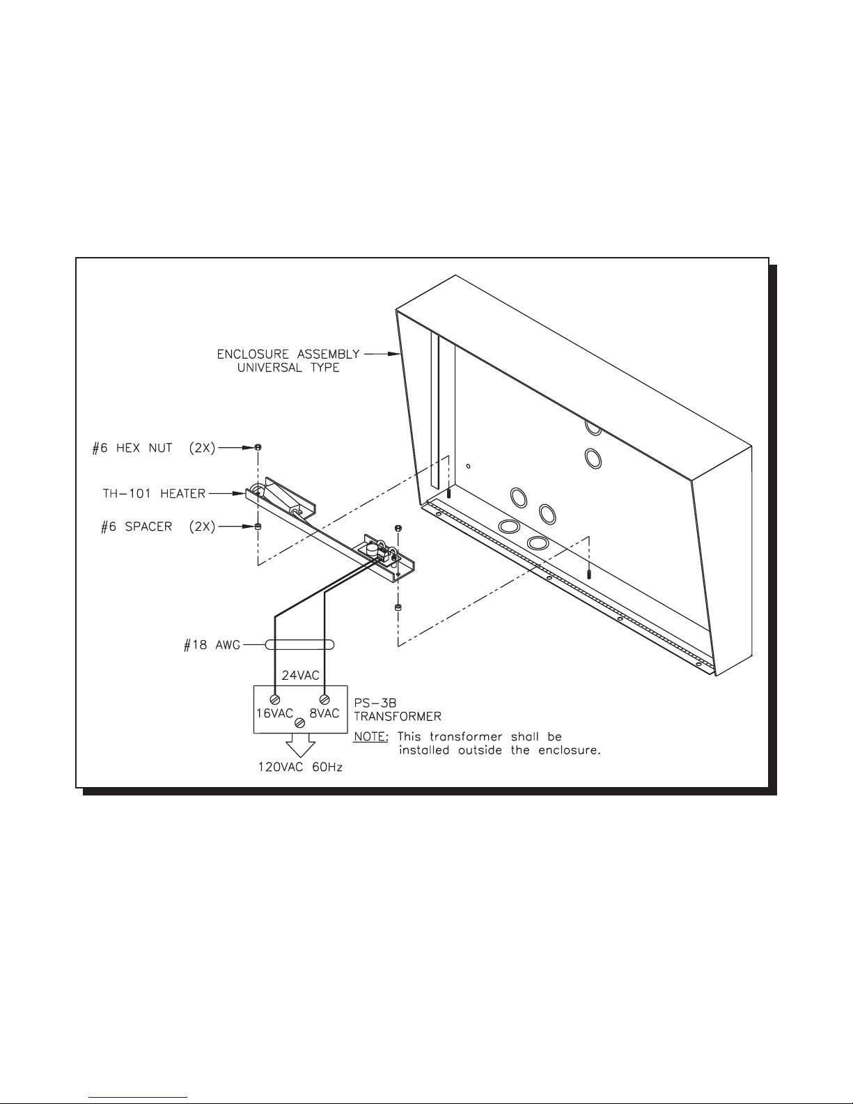
MOUNTING THE THERM O STAT HEATER KIT MODEL TH-101 (OPTIONAL)
Mount the Heater Kit according to Fig 2A . Install the TH-101 Heater into bottom left hand corner of the universal
enclosure using the two spacers and two hex nuts provided. Use a pair of #18 AW G wires to connect from the
TH -1 0 1 u n it to 24 V A C ta p o n the P S -3 B tran s fo rmer. T h e tran s fo rmer mus t b e in sta lled o u tsid e th e en c los ure .
Fig. 2A: HEATER INSTALLATION
MOU NTING TH E CO NT INENTAL TYPE LOBB Y/ENTRY PANEL
MIRCOM TECHNOLOGIES LIMITED, 9500 Series: No Subscriber Line Page 14
Page 18
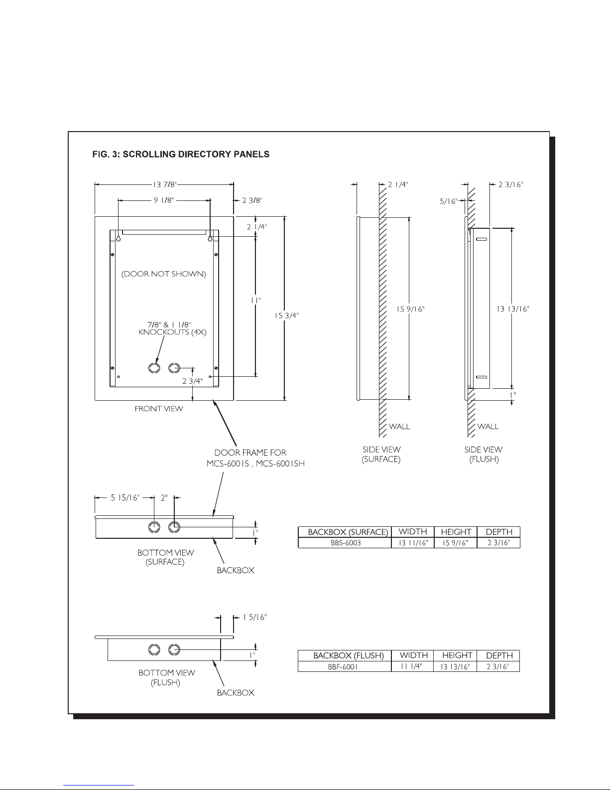
Mount the panels as shown on FIG.3 (for scrolling) or FIG.3A (for non-scrolling) using the supplied screws.
MIRCOM TECHNOLOGIES LIMITED, 9500 Series: No Subscriber Line Page 15
Page 19
MOUNTING THE M AGNETIC LETTER KIT MLK-070 (OPTIONAL)
Mo unt th e Mag n e tic Le tter Kit acc o r d in g to th e Insta lla tio n Instructio n th at co me s w ith the K it. T h is kit is u s e d on ly
for C on tine n tal type lobb y/en try pa n el.
MIRCOM TECHNOLOGIES LIMITED, 9500 Series: No Subscriber Line Page 16
Page 20
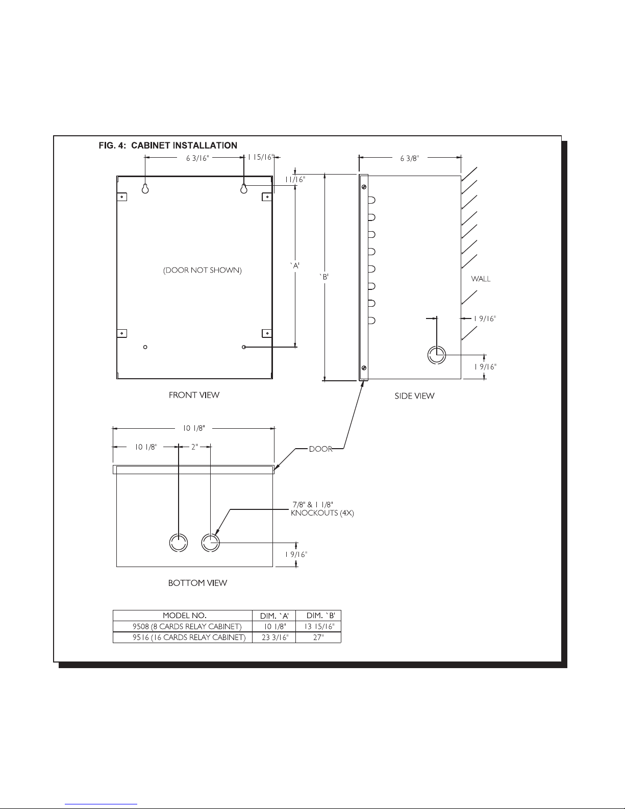
MOU NTING TH E DEC ODER/RELAY CABINET
Mount the Decoder/Relay Cabinet as shown on FIG. 4 using the supplied screws.
MIRCOM TECHNOLOGIES LIMITED, 9500 Series: No Subscriber Line Page 17
Page 21

ELECTRONIC MODULES INSTALLATION INSTRUCTIONS
MOUNTING THE 9501A, 9502A, or 9503 CONTROLLERS
Mount the controllers according to their respective installation instructions and follow the precautions mentioned on the
package. It is import ant to note that these modules are sensitive to electrostatic di scharge and must be handl ed properly. To
avoid static discharge, we recommend touching a metallic object before opening the packages and handling these modules.
These Controllers can be mounted on either Universal or Continental type lobby/entry panels.
MOUNTING THE MD-345 (Aux. Relay Board)
Mount the board as shown on the installation instructions that come with the module.
RELAY CARDS MODEL 9512 INSTALLATION
Install the relay cards by matching the polarizing plastic peg and the keyhole on the decoder/mother board. No configuration
or jumper setting is required. All plugged-in relay cards are recognized automatically by the system. Connect the 6 ft.
Amphenol Cables models 9106 (standard), 9106E (interface to existing RJ-71A BIX Blocks), 9106BC or 9406 (octopus) to
the relay cards and tighten the screw(s) to secure the cables to the plates.
SYSTEM WIRING INSTRUCTIONS
WIRING THE 9501A (Main Controller) TO 9508 or 9516 (Relay Cabinets)
Note that the Relay Control wiring (Data, Clock, Latch, Gnd) needs to be shielded 4-wire 22AWG cable. The shields must be
connected to Earth Ground at each terminating point. Also note that the Relay Control line “COM(-)” (marked “GND” on some
older boards) is a system “Common” and MUST NOT be connected to Earth Ground !
FIG.5 COMMUNICATION LINK WIRING
MIRCOM TECHNOLOGIES LIMITED, 9500 Series: No Subscriber Line Page 18
Page 22

RELAY CABINET'S DECODER/MOTHER BOARD JUMPER CONFIGURATION
Install jumpers as shown in FIG. 6.
WIRING THE DOOR STRIKE TO 9501A, 9502A, or 9503 (Controllers)
Wire the Door Strike as shown in FIG. 7.
MIRCOM TECHNOLOGIES LIMITED, 9500 Series: No Subscriber Line Page 19
Page 23

WIRING THE ELECTROMAGNETIC DOOR LOCK TO 9501A, 9502A, or 9503 (Controllers)
Wire as shown in FIG. 8.
WIRING THE LOCK-BACK SWITCH TO 9501A, 9502A, or 9503 (Controllers)
Wire the Lock-Back Switch as shown in FIG. 9 to enable automatic door-open timer cut-off.
MIRCOM TECHNOLOGIES LIMITED, 9500 Series: No Subscriber Line Page 20
Page 24

WIRING THE DOOR OVERRIDE (Postal Lock & Fire Alarm) to 9501A, 9502A, or 9503 (Controllers)
Wire as shown in FIG.10.
WIRING THE MUSIC SOURCE TO THE 9501A CONTROLLER
Wire the Radio or Tape Deck's audio output as shown in FIG. 11.
MIRCOM TECHNOLOGIES LIMITED, 9500 Series: No Subscriber Line Page 21
Page 25

WIRING THE AUXILIARY RELAY and MAIN ENTRANCE ACTIVE RELAY CONTACTS
Wire as shown in FIG.12.
WIRING THE SYSTEM and LAMP SUPPLIES
Wire as shown in FIG. 13.
MIRCOM TECHNOLOGIES LIMITED, 9500 Series: No Subscriber Line Page 22
Page 26

WIRING INSTRUCTION FOR MULTIPLE ENTRANCES APPLICATION
Wire as shown in FIG. 14.
WIRING THE GUARD TELEPHONE TO 9501A CONTROLLER
Wire as shown in FIG. 15.
MIRCOM TECHNOLOGIES LIMITED, 9500 Series: No Subscriber Line Page 23
Page 27

WIRING THE SPEAKER, MIC., and KEYPAD/DISPLAY ASSEMBLY TO 9501A, 9502A, or 9503 (Controllers)
Wire as shown in FIG. 16.
WIRING TO EARTH GROUND
Although the electronics of the 9500 Series System are not Earth Grounded, it is absolutely vital to have good solid Earth
Grounding connections to each enclosure; that is, a separate (do not rely on the Relay Control Wire shields to provide this
Earth Ground) ground bonding wire (preferably at least 14 AWG) that is run to the NEAREST confirmed building electrical
system ground, or cold water pipe. This is required on the 9501A, 9502A, and 9503 Lobby Panel Enclosures, and the
Decoder / Relay Cabinet(s). Newer enclosures will have a clearly marked screw connection on the back marked “CHASSIS
GROUND”. Older enclosures may be Earth Grounded via a mounting screw if the enclosure metal under the screw is sanded
clean of paint to ensure a good electrical connection.
The Relay Control Wires (see Fig.5) use 4-conductor shielded cable. At each wiring point (9501A and each MD-342 Relay
Mother Board) the cable shields are connected to the same Earth Ground as the enclosure. This Earth Ground MUST NOT
be connected to any of the four Relay Control Wires (Data, Clock, Latch, Com) themselves.
NOTE: IF PROPER GROUNDING REQUIREMENTS ARE NOT FOLLOWED AS OUTLINED, REPAIRS MAY NOT BE
COVERED BY WAR RANTY.
WIRING THE DEDICATED TELEPHONE LINE
Connect the “Outside Line” modular jack to a touch tone (DTMF) type telephone line by using the supplied telephone cord.
The “Outside Line” modular jack is located on the upper-left corner of the 9501A main controller board. The outside line is
used by the system to autodial up to 11-digit telephone number through the telephone network.
POWERING THE SYSTEM
Before powering the system, double check all the connections. When all connections are checked, power the system up and
observe the system display. If necessary, adjust the contrast as described in the Display Contrast Adjustment section.
MIRCOM TECHNOLOGIES LIMITED, 9500 Series: No Subscriber Line Page 24
Page 28

ELEVATOR RECALL (RESTRICTION) FEATURE
GENERAL OPERATION
Eleva tor- R e c all (R es tric tion ) is n ow a sta n da rd fe a ture w hic h ha s be e n implemen ted in th e 9 5 01 A /N S L s yste m.
Th e f e a tu r e o p e r a te s as s u c h : a visitor ca lls a r e s id e n t, is th e n a llo wed e n tr a n c e a t whic h p o in t t h e e n tr y d o o r is
opened and the floor relay is activated. W hen the visitor gets on the elevator, he can only access the floor of the
resident. This feature is supported from bo th the Lobb y as well as rem ote do or points-of-acces s. T he fea ture
operates by allowing the installer to (indirectly) associate the first two digits of the Resident/Tenant Code which a
visitor wo uld e n te r o n th e lo b b y keyp a d ( i.e . w h en tryin g to c a ll a R e s iden t S u ite), w ith a n e le v a to r reca ll
(restriction) relay number. This reserved relay will be activated only after a Resident makes the decision to allow
the visitor a c c es s to th e bu ilding (i.e. w he n the R e s ide nt p re s se s the d igit wh ich ha s b ee n pro g ra mmed to a c tivate
the main/remote door latch), so that the main/remote door latch and elevator recall relay are activated at the same
tim e a n d for th e s a me le n g th of time . We s u g g e st a s e p a r a te time r b e u s e d f o r e a c h e le v a to r floor r e la y.
The first two digits of the Resident/Tenant Code allow for a (theoretical) range from 01-95 relays to be reserved for
this purpose. For example, the code “1201" and “1215' would both activate the same reserved relay. For the
purposes of the Elevator-Recall (Restriction) functionality, it is assumed that both Resident/Tenant Codes (i.e.
1201 a n d 1 2 1 5 ) w o u ld b e a ssig n e d to Res id e n ts on th e s a me ( i.e . 1 2 th) flo o r . T hus , a ma x imu m o f 9 5 p o ssib le
relays (each assigned to a sepa rate floor) can be ac ces sed in this man ne r.
These elevator recall (restriction) relays can only be allocated from the last relay-cabinet in the NSL system (the
maximum number of relay cabinets is 16). If sixteen relay cabinets are not used, but Elevator-Recall (Restriction)
is requ ired , the n jumpe r th e la st re lay c ab ine t (w h ate ve r it may be i.e. th e fifth , six th e tc .) as if it were th e six tee n th
cabinet. The jumper is placed in the 16th location, refer to Figure 6 for location. The very last relay in this cabinet
is however NOT available, as it is always reserved for use by the 9501A system.
NOTE: T o have Elevator-Recall Restriction use Model 9512E Elevator-Recall Cards mounted in a 9508 8 Relay
Card C a b ine t.
Ele v a to r -Rec a ll ( R estr ic tio n ) is a v a ila b le w ith s in gle a n d multiple e n tr a n c e s a nd a re p r o g r a mme d a c c o r d in g ly.
1. SINGLE ENTRANCE - ELEVATOR-Recall (Restriction)
At the 9 50 1 A , rela ys a re pro g ra mmed to a c tivate in a ss o c iation with a s pe c ific R e s ide nt/Tena nt C o d e . R efe r to
Appendix D-1 and Programming Instructions in this manual. Only the relays in the last relay cabinet may be
programmed as Elevator-Recall (Restriction) relays.
For example: A single entrance system consists of a 9501A and 3 relay cabinets. The last relay cabinet may be
us e d a s E le v a tor-Rec a ll (Res tr ic tion) r e la ys u s in g the Mod e l 9 5 1 2 E Ele v a to r -Rec a ll Card s (max imu m 8 c a r d s in
the c a b in e t) . The r e fore it is r e c o mme n d e d to a sso c ia te a ll r e s id e n ts on th e s a me f lo o r w ith o n e Eleva tor-Rec a ll
(Restriction) relay. Sample programm ing at the 9501A would be as such:
Elevator-Recall (Restriction) Relay
Residen t/Ten an t C o de (the last relay cabinet)
1201 12
1202 12
1203 12
1301 13
Looking at the info rmation a bo v e, th e firs t tw o d igits o f th e R e s ide n t/T en a n t C od e re pre s e nts th e re s ide n t’s floo r.
Therefore all residents on the twelfth floor activate the same Elevator- Recall (Restriction) relay number 12 on the
first relay M o d el 95 1 2 E E lev a tor- R e ca ll Re lay C a rd in the las t re lay ca b ine t.
2. MULTIPLE ENTRANCES - ELEVATOR-RECALL (RESTRICTION)
MIRCOM TECHNOLOGIES LIMITED, 9500 Series: No Subscriber Line Page 25
Page 29

For systems with more than one entrance, the 9502A must be programmed for the Elevator-Recall (Restriction)
appli cation.
NOTE: A 9502A IS USED FOR MULTIPLE POINTS OF ENTRY. ONE 9502A IS REQUIRED FOR EACH
ENTRANCE IN ADDITION TO THE MAIN LOBBY ENT RANCE.
The U NIT-ID c o d e is a n umbe r w h ich is p ro gra mmed w ith e ac h R E MOTE 95 0 2 A sys tem an d ca n ran g e fro m 0-9 .
When the 9502 A is to be used in an Elevator-Rec all (Restriction) application, a value of 1 to 8 (representing
relay card 1 to 8 in the last relay cab inet) must be programm ed . A 9502A prog ramm ed with a value of either 0
or 9 will be excluded from the Elevator-Recall ( Restriction) functionality. The UNIT-ID value for the (base) 9501A
system is N OT programm ab le and always has a value of 1.
The method for association between the first two digits of the Resident/Tenant Code and the actual relay number
is outlined here for use with a 9502A:
1. At the 9502A, the UNIT-ID identifies which relay card number (1 through 8 with 12 relays per card) in
cabinet 16 (or the last cabinet), will be the st a rting address for the Elevator Restriction relays.
2 The UNIT-ID als o id e n tif ie s (0 o r 9 ) that a p a r tic u la r 9 5 0 2 A u nit is to b e e x c lu ded fr o m th e E le v a tor-Rec a ll
(Restriction) feature (Default/Normal opera tion).
3. In order for the 9501A to k now wha t Res ident/Tenan t Cod e has be en en tered from a Remote (9502A )
keypad, it is necessary that the programmed relay numbers match exac tly the programmed
Resident/Tenant Codes (specific to that particular 9502A panel). For example:
At the 9502A At the 9501A
Resident/Tenant Code Relay Code Resident/Tenant Code Relay Code
0107 0107 0107 0000
0202 0202 0202 0001
EXAMPLES:
a) Exclude REMOTE (9502A) panel from Elevator-Recall (Restriction) feature:
Program the 9502A with a Unit-ID code of 0 or 9.
Prog ra m the 9 50 2 A w ith R e s ide nt/T e n a nt C o d es a n d re lay nu mbe rs tha t w e re p ro g ra mm e d at th e 9 5 01 A . In
this instance the 9502A will send the specific relay number to the 9501A to activate and ensure a
connection to this particular Resident Suite.
Whe n th e 9 5 01 A s e es a U N IT-ID c od e of 0 o r 9, it will take th e re lay n umbe r s e nt b y the 95 0 2A a n d activate
the c o n n e c tion. A t t h e e n d o f th e c a ll, the la s t relay in c a b in e t 1 6 will be a ctiva te d ( D e f a u lt/ Norma l
operation).
b) Include REMO T E (9502A) panel in Elevator-Recall (Restriction) feature:
Program the 9502A with a UNIT-ID code of 1 to 8, depending on the desired starting relay card number.
Prog ra m the 9 50 2 A w ith R e s ide nt/T e n a nt C o d e s u s ed a t the 95 0 1A a n d in pu t the s ame R es id en t/T e n an t
Code number under the Relay # heading. For example: if the Resident/Tenant Code is 0107 then the
Rela y# is 0 10 7 als o a t the 95 0 2 A . T he 9 50 1 A R e s ide nt/T e n a nt C o d e s a n d th e 95 0 2A R e s ide n t/T e na n t
Co d e s an d R e la y n um b e r s a t t h e 9 5 0 2 A s h ould b e id e n tic a l.
W hen the 9501A “sees” a UNIT-ID code of 1 through 8, it will take the relay number sent by the 9502A and
perform a “lookup” on the (local) 9501A programmed Resident database in order to resolve the actual relay
number to be activated. At the end of this call, the specific Elevator-Recall (Restriction) relay will then be
acti vated.
EXAMPLES:
If a 9502A is programm ed with a UNIT- ID = 1 and a Resident/Tenant Code of “1215" is entered on the
MIRCOM TECHNOLOGIES LIMITED, 9500 Series: No Subscriber Line Page 26
Page 30

keypad at the entrance (on the 9501 A), then the Elevator-Rec all (Restriction) relay number 12 (twelfth
rela y o n c a r d n u mb e r 1 ) in th e las t c a b in e t will be a c tiv a te d . If the R e side n t/Cod e is 1 5 15, th e n the re la y
number 15 (third relay on card number 2) will be activated.
If a 9502A is programm ed with a UNIT-ID =3 and a Resident code of “1215" is entered (remote), then the
Elevator-Recall (Restriction) relay number 36 (twelfth relay on card number 3) in the last cabinet will be
activated. If the Resident/Cod e is 1515 , then the relay num ber 39 (third relay on card number 4) will be
acti vated.
9502A 9512E RELAY CARDS IN LAST RELAY CABINET
UNIT-ID 1
Relay Card Number 1 ( Relay number 1 to 12)
UNIT-ID 2
UNIT-ID 3
UNIT-ID 4
UNIT-ID 5
UNIT-ID 6
UNIT-ID 7
UNIT-ID 8
Relay Card Number 2 ( Relay number 13 to 24)
Relay Card Number 3 (Relay number 25 to 36)
Relay Card Number 4 (Relay number 37 to 48)
Relay Card Number 5 (Relay number 49 to 60)
Relay Card Number 6 (Relay number 61 to 72)
Relay Card Number 7 (Relay number 73 to 84)
Relay Card Number 8 (Relay number 85 to 95)
LAST RELAY NOT USED
NOTES: FIRST TWO DIGITS OF THE RESIDENT/TENANT CODE REPRESENTS THE ELEVATOR-
RECALL (RESTRICTION) RELAY NUMBER.
WH E N U S IN G E L E VATOR -R E C AL L (R E STRIC T IO N ) IT IS N E C E S SARY T O U S E A
SEPARATE TIMER FOR EACH OF THE FLO OR RELAYS.
WIRING THE 9512E ELEVATOR-RECALL RELAY CARD
The 9512E Elevator-Recall Relay Card provides Common (C) and Normally Open (NC) contacts marked on the
board silkscreen. The very first relay marked Aux Rly is an auxiliary relay which is activated any time another relay
on the bo a rd is a ctiva ted . T h e rela ys a va ilable fo r E le va tor- R e ca ll (R es tric tion) a re lab e lled R e lay 1 to R e lay 12 .
W iring is achieved at the terminal block which is removable for easy installation.
MIRCOM TECHNOLOGIES LIMITED, 9500 Series: No Subscriber Line Page 27
Page 31

PROGRAMMING INSTRUCTIONS: SCROLLING DIRECTORY
Before programming the system, obtain the required information by using the forms provided in APPENDICES "D1 and D -2 ". S o me info rmation may be fo un d on A P P E N D ICES "B-1 a n d B -2 ".
The following programming information pertains to both the 9501A and the 9502A unless otherwise specified.
After the system initializations (power up), the display should appear as shown below.
< MIRCOM >
Enter Resident Code
to view directory
press * UP # DOWN
This is the Normal Mode of th e s ys te m. The s ys tem will a c c e p t a ll v a lid A cce s s Cod e s b y e n tering the m d ire c tly
on the keypad. Use the * or # key to scroll "up or down" the resident directory list. Pressing the * or # key
mom entarily will scroll "up or down" the directory list one name at a time. Holding the * or # key will scroll "up or
down" continuously and stop scrolling when the key is released.
Before entering the Programming Mode for the first time, it is recomm ended to restore the factory default Master
Code *999 by shorting the reset pins for approximately 3 seconds. Please see page 34, Fig. 18 for reset pins
location.
Note: Shorting the reset pins will only restore the factory default Master Code *999 and will not affect any
programmed information.
ENTERING PROGRAMMING MODE
Wh ile in th e N ormal Mod e , p r e s s " 0" then enter the MASTER CODE (factory default is *999) to enter the
PROGRAM MING M OD E.
Pressing "0", the screen should appear ...
< MIRCOM >
***** _ _ _ _ *****
*******************
-Keyless Entry Mode-
Pressing "*", the next screen should appear...
< MIRCOM >
***** * _ _ _ *****
*******************
-Program Code Entry
Enter Master Code (default is 999), the next screen should appear...
< MIRCOM >
PROGRAM MODE
-Please Wait-
-Program Code Entry-
for a few seconds, then the screen should change to...
<<< PROGRAM MODE >>>
Enter the three
digit program code
[Use *888 for Menu]
This is the P R OG R A M MODE men u. A t this sta g e, th e s ys tem is wa iting fo r v alid p ro g ramming c o de .
Important note: Before programming the system for the first time, it is recommended to clear the memory and restore all factory defaults
by using a special command *5*5 while in the Program Mode menu . Since this special command (*5*5) is a destructive
command which can erase all the programmed information without the provision to undo, the user must take precaution
when using this command.
There are two ways to program the system.
MIRCOM TECHNOLOGIES LIMITED, 9500 Series: No Subscriber Line Page 28
Page 32

1. By using * 888 for Me n u D rive n type o f pro g ra mming.
2. By using the Direct Access Programming Codes for manual programm ing. Entering these codes will lead the
user directly to the desired function. The Direct Access Programming Codes are listed in the table below.
Code Function Factory
Default
*000 Exit Programming Mode *000 n/a NONE
*101 Enter Resident/Tenant Codes
and Relay Numbers
*202 R eview Resident/Tenant
Codes, Relay Numbers and
Resident/Tenant Names
*303 Enter Ke yles s E n try C o de s B lan k See w o rk s h e et 4 digits
*404 Review Ke yles s En try C o de s Blank See w o rk s h ee t 4 digit code to
*505 Chang e M a s ter Code *999 *___ ___ __ _ 3 digits
*606 Chang e N u mbe r of Ring C ycle s 6 cycles ___ __ _ cyc les 2 digits
*707 Set Doo r Open T imer 10 se c o nd s _ __ _ __ s e co n ds 2 digits
*808 Set On Lin e Time r 60 se c o nd s _ __ _ __ s e co n d s 2 dig its
*909 Select MULTIPLE/SINGLE
Entrance
Blank See worksheet 4 digit resident
Blank See w orkshe e t Up to 23 d igits to
Multi (00) ___ ___ 00 Multi or
Program Choices
co d e a n d 4 d ig it
relay number
review or d e lete
4 + 4 +15
review or d e lete
11 Single (2 digits)
*111 Enter 1st 11-digit Telephone
Number
*222 Enter 2nd 11-digit Telephone
Number
*333 Auto Programming
Residents’/Tenants’ Dial Codes
*777 Select Digit for Hold 3 __ 1, 2 or 3
Blank (_) _ _ _ _ _ _ _ _ _ _ 4-digit area code
and 7 d ig it
telephone number
Blank (_) _ _ _ _ _ _ _ _ _ _ 4-digit area code
and 7 d ig it
telephone number
None Qty_ _ _ Code:_ _ _ _ 3-digit maximum
reside n t ca p ac ity
4-digit starting point
for resident codes
"NO MANUAL" MENU DRIVEN PROGRAMMING USING *888
MIRCOM TECHNOLOGIES LIMITED, 9500 Series: No Subscriber Line Page 29
Page 33

W hile in the programm ing mode, enter the "*888" to gain access to the programm ing menu. After entering *888,
the sc re e n s h o uld a p p ea r...
[1=Bck] [3=Fwd]
Welcome to the NSL
On-Line Help Menu!
[*=Abort] [#=Yes]
1 and 3 keys are for scrolling backward or forward the feature menus.
# to access the displayed feature.
* to quit, exit, ca nc e l or a b ort.
Press 3 for the ne x t menu . T h e sc re e n sh o uld ap p ea r...
[1=Bck] [3=Fwd]
Do you want to exit
from PROGRAM Mode?
[*=Abort] [#=Yes]
1 inactive key
3 key to the first feature menu.
# key to exit to Normal Mode.
* key to Programming Mode menu
Note: Repeat the above scrolling process (i.e. pressing keypad 3) to locate the desired feature. To ex it to
Norm al Mode, en ter *000 while in the PROGR AM MO D E m enu.
Press 3 again for the next menu.
MANUAL ENTRY OF RESIDENTS'/TENANTS’ DI AL CODES a nd RELAY #
Residents'/Tenants’ D ial Codes and Relay # can b e en te red in th e fo rma t of 1 , 2, 3 , or 4 d igits (les s tha n 4 d igits
must be preceded by 0's). These codes are used to call the residents using the Entry Panel's keypad. Use the
info r ma tio n g iv e n o n A PPE ND ICES "D -1 a n d D-2 " to p r o g r a m th e Res id e n ts'/T e n a n ts’ Dial Codes and Relay #.
To enter codes manually, scroll through until you reach the feature as shown below.
[1=Bck] [3=Fwd]
Do you want to enter
TENANT Codes ?
[*=Abort] [#=Yes]
Press # to acce s s fea tu re. The s cre e n s ho u ld d isp lay...
Enter: 000x for one (1) digit dial code
-Program Options- Enter: 00xx for two (2) digits dial code
Code Relay# Enter: 0xxx for three (3) digits dial code
_ _ _ _ _ _ _ _ Enter: xxxx for four (4) digits dial code
Please enter choice: To call a resident with two digits dial codes, simply enter xx
Enter Resident/Tenant Dial Code and Relay/Line number as per APPENDICES D-1and D-2. When you make a
mistake and wish to re-enter the code, press * to enter code again. After entering the Code and Relay number, the
nex t sc re en s h ou ld d isp lay...
Where: 0 - Zero, x - Resident Dial Code (digit 0 to 9)
MIRCOM TECHNOLOGIES LIMITED, 9500 Series: No Subscriber Line Page 30
-Program Options-
* = Abort, # = Store
xxxx xxxx
Page 34

Please enter choice:
Press # to Store or * to abort entry. Repeat this process until all codes are entered. When finished, press * to
return to PRO G R AM MO D E menu. T o quit, enter *000 while at PROGRAM MO DE m enu to return to NORMAL
MODE.
NOTE: IF ELEVATOR-RECALL (RESTRICTION) IS TO BE USED, PLEASE DESIGNATE FIRST TWO DIGITS
OF RESIDENT’S CODE AS THE RESIDENT’S FLOOR NUMBER. FOR EXAMPLE: A RESIDENT LIVES ON
THE SEVENTH FLO OR , THEIR RESIDENT CODE SHO ULD BE 07XX W HERE XX IS A NUMERIC NUMBER
(01 T O 95) OF Y OUR CHOICE . PL E ASE R E F E R T O TH E E L E V ATOR-RE CALL (R E S TRIC TION) SE C T ION IN
THIS MANUAL FOR FURTHER INFORMATION.
ENTRY, REVIEW, EDIT or DELETE DIAL CODES AND RESIDENTS'/TENANTS’ NAMES
To enter, review, edit or delete Dial Codes and Resident /Tenant Names, scroll through until you reach the feature
as shown below.
[1=Bck] [3=Fwd]
Do you want to edit
TENANT Names ?
[*=Abort] [#=Yes]
Press # to acc es s th e fe a ture . The dis p lay sh o uld ap p ea r...
====TOP-OF-LIST=====
xxxx: <== Second line with “:” displayed can
xxxx be selected by pressing “0".
xxxx Where: xxxx are the Dial Codes.
Note: Pre s s an y nu mber to ex it.
Press * or # to sc roll (re vie w) "u p o r d o wn" th e list . To enter ,e d it, a nd d e le te th e r e s id e nt/tenan t n a me , s c r o ll u n til
the de s ired A c ce s s C o de an d R e s ide nt/T e n a nt N a me is in the se c o nd line o f th e d isp lay.
Press "0" to enter, edit or d e lete Dial Code and Resident /Tenant Name. The nex t sc re e n sh o uld ap p ea r....
-Program Options-
CODE:xxxx Relay:xxxx
NAME:xxxxxxxxxxxxxxx
Please enter choice:
1and 3 to scroll "up or down" the character set. Character Set table is given on Appendix E.
7and 9 to move the c urs o r "left o r rig ht".
# to delete the displayed Dial Code and Resident Name.
CAUTION!: Deleting a Dial Code and Resident Name will also delete the corresponding Relay #.
After entering resident/tenant name, press * . The ne xt s c re en s ho u ld a pp e ar...
-Program Options-
* = Abort, # = Store
Name:xxxxxxxxxxxxxxx
Please enter choice:
Press * to abort or # to store entry. Repeat the above process until all residents' names are entered. When
finished, press * to return to PRO G R A M M O D E menu. To q uit, enter *000 while at P R OGRAM MODE menu to
return to NORMAL MOD E.
MIRCOM TECHNOLOGIES LIMITED, 9500 Series: No Subscriber Line Page 31
Page 35

AUTO PROGRAMMING RESIDENTS'/TENANTS’ DIAL CODES
This feature is provided to allow the user to program the D ial Codes au tomatically. In addition, the user can spec ify
the "quantity" (number of codes) and "access codes start number" for quick installation.
Scroll through until you reach the feature as shown below.
[1=Bck] [3=Fwd]
Do you want to AUTO-
PROGRAM Codes ?
[*=Abort] [#=Yes]
Press # to acc es s the fe a ture . T h e dis pla y sh ou ld a p pe a r...
-Program OptionsQuantity: _ _ _ (<xxx) <----where: xxx is the maximum resident capacity
Codes start at: _ _ _ _ <----4 digits access codes
Please enter choice:
CAUTION!: Using A u to P ro g ra m w ill rep lac e a ll thos e pre v iou s ly p ro gra mm ed c od e s.
En te r th e d e s ir e d "q u antity" ( n u mb e r o f c o des ) a nd "s ta r t n u mb e r " f o r Dial Cod e s . The s ys tem sh o u ld
automatic a lly p r o g r a m th e c o d e s in c r e me n tally by on e (1) . P le a s e no te th a t t h e Rela y/L in e Numb e r will alw a ys
start at 0000. For example, the start number is 1500, the data stored in the memory should be as shown below.
Code Relay number
1500 0000
1501 0001
1502 0002
etc.
While the sys tem is p ro gra mming, the mes sa g e will app e a r...
Now PROGRAMING!
- Please Wait-
W hen finished, the system should exit to the PROGRAM MO DE menu. To quit, enter *000 to return to NORMAL
MODE.
PROGRAMMING KEYLESS ENTRY CODES
The system can provide up to 1000 Keyless Entry Codes for residents and 5 spares for building management. The
Keyless Entry Codes allow authorized residents/tenants to enter a code directly at the keypad to release the door
without the necessity of calling the resident. For obvious reasons, keyless entry codes should be kept well guarded
and controlled.
[Oper ation: press "0" followed by the four digit Keyless Entry Code]
To enter Keyless Entry Codes, scroll through until you reach the feature as shown below.
[1=Bck] [3=Fwd]
Do you want to enter
KEYLESS Codes ?
[*=Abort] [#=Yes]
Press # to acc e s s the fe atu re . T h e d isp lay s ho u ld a pp e ar...
MIRCOM TECHNOLOGIES LIMITED, 9500 Series: No Subscriber Line Page 32
Page 36

-Program OptionsKEYLESS Entry
Code #_ _ _ _
Please enter choice:
Enter the four digits Keyless Entry Code. If you make a mistake or wish to re-enter the code, press * to enter code
again . T h e n e xt d isp lay s ho u ld c ha n ge to ...
-Program Options-
* = Abort, # = Store
Code # x x x x
Please enter choice:
Press * to abort or # to store entry. Repeat this process until all codes are entered. We recommend not to use the
same k e yless e ntry c od e . P re ss a ny nu mbe r fr om 1-9 to ex it to P R OGRAM M ODE men u w he n finish e d . T o qu it,
enter *000 while at PROGRAM M OD E m enu to return to NORMAL MODE.
REVIEW AND DELETE KEYLESS ENTRY CODES
To review and delete Keyless Entry Codes, scroll through until you reach the feature as shown below.
[1=Bck] [3=Fwd]
Do you want to edit
KEYLESS Codes ?
[*=Abort] [#=Yes]
Press # to acc es s th e fe a ture . The dis p lay sh o uld ap p ea r...
-Program Options-
Code To Review
# _ _ _ _
Please enter choice:
Ente r the K eyles s E ntry C o d e to re view o r d ele te. T h e ne x t dis pla y sh ou ld a p pe a r...
-Program OptionsKEYLESS Entry
Code # x x x x
Please enter choice:
Press 1 or 3 to scroll (review) "up or down" the list. To delete the displayed code, press #.
W hen finished, press * to exit to PROG R AM MO D E menu for prog ramm ing other functions. To q uit, enter *000
while at PROGRAM MO D E menu to return to NORMAL MODE.
REPROGRAMMING MASTER CODE
Master Code (factory default is *999) ma y b e c h a n g e d to a n y d e s ir e d th r e e (3) dig its co d e n u mb e r . S in c e this
code is used to access all levels of programm ing, it would be a good idea to change the code to one that will be
known only by the installer or managem ent personnel. Please enter the new Master Code in the space provided
below fo r fu ture re fe re n c e.
New Master Code: ___________________ Date: ______________________
MIRCOM TECHNOLOGIES LIMITED, 9500 Series: No Subscriber Line Page 33
Page 37

To change the MASTER CODE, scroll through until you reach the feature as shown below.
[1=Bck] [3=Fwd]
Do you want to edit
the MASTER Code ?
[*=Abort] [#=Yes]
Press # to acc e s s the fe atu re . T h e d isp lay s ho u ld a pp e ar...
-Program Options-
MASTER Code
*_ _ _
Please enter choice:
Enter the New Master Code.Please do not use *888 for Master C ode.T he nex t display should appear.
-Program Options-
* = Abort, # = Store
* x x x
Please enter choice:
Press * to abort or # to store en try. T h e n e xt d isp lay sh o u ld ap p e ar...
-Program Options-
Press *
To exit
Please enter choice:
Press * to exit to PROGR A M M O D E menu. To q uit, enter *000 while at PR OGRAM MODE menu to re tu rn to
NORMAL MO DE.
Note: To restore factory default Master Code, please see FIG. 18 for location of reset pins.
SET DOOR TIMER
To change Door-Open Timer (factory default is 10 seconds), scroll through until you reach the feature as shown
below .
[1=Bck] [3=Fwd]
Do you want to edit
the Door-Open Timer?
[*=Abort] [#=Yes]
Press # to acc es s th e fe a ture . The dis p lay sh o uld ap p ea r...
-Program OptionsDoor-Open Timer
00 to 99 Sec. x x <----99 seconds max.
Please enter choice:
Ente r the de s ired d oo r-o p en p erio d . T h e n e xt d isp lay sh o u ld ap p e ar...
-Program Options-
* = Abort, # = Store
00 to 99 Sec. x x
Please enter choice:
MIRCOM TECHNOLOGIES LIMITED, 9500 Series: No Subscriber Line Page 34
Page 38

Press * to abort or # to store entry. To quit, enter *000 while at the PROGRAM MO DE m enu to return to NORMAL
MODE.
ELEVATOR-RECALL RESTRICTION (9502A ONLY)
The system can provide elevator-recall (restriction). Scroll down to the following feature.
[1=Bck] [3=Fwd]
Do you want to edit
Elevator-Recall ID?
[*=Abort] [#=Yes]
Pres s # to ed it. T he men u s h o uld ap p ea r ...
-Program OptionsElevator-Relay
Card 1-8, 9-0 0
Please enter choice:
En te r o n e d ig it 1 to 8 f o r Elev a to r R e s tr iction featu r e . E n ter 0 o r 9 fo r n o r mal o pera tion w ith o u t elevator -r e c a ll
(re s tr ic tio n ) . F o r mo re in f o r ma tio n s e e the E le v a to r -Rec all (R e s tr ic tio n ) s e c tion in th is ma n u a l.
SET ON -LINE TIMER (9501A only)
To change the On-Line period (factory default is 60 seconds), scroll through until you reach the feature as shown
below .
[1=Bck] [3=Fwd]
Do you want to edit
the On-Line Timer?
[*=Abort] [#=Yes]
Press # to acc e s s the fe atu re . T h e d isp lay s ho u ld a pp e ar...
-Program OptionsOn-Line Timer
00 To 99 Sec. _ _ <----99 seconds max.
Please enter choice:
Ente r the O n -L ine pe riod . T h e ne x t dis pla y sh ou ld a p pe a r...
-Program Options-
* = Abort, # = Store
00 To 99 Sec. x x
Please enter choice:
Press * to abort or # to store entry. To quit, enter *000 while at PROGRAM M OD E m enu to return to NORMAL
MODE.
MULTIPLE / SINGLE ENTRANC E SE LECT (9501 A only)
To select M ultiple or Single entrance (factory default is single entrance), scroll through until you reach the feature
as shown below.
MIRCOM TECHNOLOGIES LIMITED, 9500 Series: No Subscriber Line Page 35
[1=Bck] [3=Fwd]
Do you want to edit
Single/Multi option?
[*=Abort] [#=Yes]
Page 39

Press # to acce s s the fe atu re . T h e d isp lay s ho u ld a pp e ar...
-Program OptionsMulti or Single
M=00 S=11 _ _
Please enter choice:
Enter 00 for multiple entrances or 11 fo r s in gle en tra nc e . T h e ne x t disp lay s ho u ld a pp e a r...
-Program Options-
* = Abort, # = Store
M=00 S=11 x x
Please enter choice:
Press # to store or * to abort entry. To quit, enter *000 while at PROGRAM MODE menu to return to NORMAL
MODE.
RING CYCLE SELECT (9501A o nly)
To change the number of Ring Cycles (factory default is 6 cycles), scroll through until you reach the feature as
shown below.
[1=Bck] [3=Fwd]
Do you want to edit
the Ring cycles ?
[*=Abort] [#=Yes]
Press # to acc e s s the fe atu re . T h e d isp lay s ho u ld a pp e ar...
-Program Options# RING Cycles
00 To 99 Cycl. _ _ <----99 cycles max.
Please enter choice:
Ente r the nu mbe r o f ring c ycles . T h e ne x t dis pla y sh ou ld a p pe a r...
-Program Options-
* = Abort, # = Store
00 To 99 Cycl. x x
Please enter choice:
Press * to abort or # store entry. To quit, enter *000 while at PROGRAM M O DE m enu to return to NORMAL
MODE.
SET CLOCK (NOT AVAILABLE - DO NOT USE)
To set the clock, scroll through until you reach the feature as shown below.
MIRCOM TECHNOLOGIES LIMITED, 9500 Series: No Subscriber Line Page 36
Page 40

[1=Bck] [3=Fwd]
Do you want to set
the Time-of -Day ?
[*=Abort] [#=Yes]
Press # to acc e s s the fe atu re . T h e d isp lay s ho u ld a pp e ar...
-Program OptionsHr Mn Sc
_ _ : _ _ : _ _ <----Hour : Minute : Second
Please enter choice:
Enter the Tim e-of-D ay. To quit, enter *000 while at PROGRAM MO DE m enu to return to NORMAL MODE.
TWO 11-DIGITS TELEPHO NE NUMBER ENTRY (9501A)
The system has a built-in Dedicated Telephone Jack that can be connected to a standard residential jack (RJ11/CA-11). The user can program two ( up to 11-digit) telephone numbers that can be auto-dial through the
teleph on e ne tw o rk . E ac h tele ph o n e n u mber h a s its ow n dia l co de . T o take ad va nta g e of th is u niq ue fe a ture , a
touch tone (DTMF) line is required.
To enter the FIRST 11-digit telephone number, scroll through until you reach the feature as shown below.
[1=Bck] [3=Fwd]
Do you want to set
the 1st 11-digit # ?
[*=Abort] [#=Yes]
Press # to acc e s s the fe atu re . T h e d isp lay s ho u ld a pp e ar...
-Program Options(1) Code: _ _ _ _
_ - _ _ _ - _ _ _ - _ _ _ _ <----up to 11 digits telephone number
Please enter choice:
Enter Dial Code and telephone number. If less than 11 digits are required, simply press # to blank the remaining
digit(s). When you make a m istake and wish to re-enter the code, press * to enter code again. After entering the
teleph on e nu mbe r, the d isp lay sh o uld ap p ea r...
-Program Options-
* = Abort, # = Store
x - x x x - x x x - x x x x
Please enter choice:
Press * to abort or # to store en try. To quit, enter *000 while at PROGRAM MO DE m enu to return to NORMAL
MODE.
To enter the SECOND 11-digit telephone number, scroll through until you reach the feature as shown below.
[1=Bck] [3=Fwd]
Do you want to set
the 2nd 11-digit # ?
[*=Abort] [#=Yes]
MIRCOM TECHNOLOGIES LIMITED, 9500 Series: No Subscriber Line Page 37
Page 41

Press # to acc e s s the fe atu re . T h e d isp lay s ho u ld a pp e ar...
-Program Options(2) Code: _ _ _ _
_ - _ _ _ - _ _ _ - _ _ _ _ <----up to 11 digits telephone number
Please enter choice:
Enter Dial Code and telephone number. If less than 11 digits are required, simply press # to blank the remaining
digit(s). When you make a m istake and wish to re-enter the code, press * to enter code again. After entering the
teleph on e nu mbe r, the d isp lay sh o uld ap p ea r...
-Program Options-
* = Abort, # = Store
x - x x x - x x x - x x x x
Please enter choice:
Press * to abort or # to store en try. To quit, enter *000 while at PROGRAM MO DE m enu to return to NORMAL
MODE.
RING PATTERN SELECT (9 501A only)
The system allows the user to adjust the ringing pattern as required. Factory default is set to a distinct ringing
pattern. Norm al or Standard N orth A merican ringing pattern can be selected for applications where ringing pattern
is critical; es p ec ially for o lde r an s w e ring mach ine s tha t on ly ac c ep t no rmal ring ing p atte rn .
To change the ringing pattern, scroll through until you reach the feature as shown below.
[1=Bck] [3=Fwd]
Do you want to edit
ringing-pattern ?
[*=Abort] [#=Yes]
Press # to acc e s s the fe atu re . T h e d isp lay s ho u ld a pp e ar...
-Program OptionsDistinct/Normal
D=15 N=38 _ _ <---- 38 for North American ringing pattern
Please enter choice:
Enter 15 for Mircom's distinct ringing pattern or 38 for Normal or Standard North American ringing pattern. Enter
any nu mber fo r o th e r de s ired ring ing p atte rn . Afte r e n terin g the se lec tion , the d isp lay sh o uld ap p ea r...
-Program Options-
* = Abort, # = Store
D=15 N=38 x x
Please enter choice:
Press * to abort or # to store en try. To quit, enter *000 while at PROGRAM MO DE m enu to return to NORMAL
MODE.
SORT RESIDENTS'/TENANTS’ NAMES
To sort Residents'/Tenants’ names, scroll through until you reach the feature as shown below.
[1=Bck] [3=Fwd]
Do you want to sort
the tenant names ?
[*=Abort] [#=Yes]
Press # to sort Reside n ts '/T en a nts ’ na mes . Wh ile the s ystem is s ortin g n a mes , the dis pla y sh ou ld a p pe a r...
MIRCOM TECHNOLOGIES LIMITED, 9500 Series: No Subscriber Line Page 38
Sorting tenant List!
Page 42

- Please Wait -
Sorting Residents'/Tenants’ names may take a few minutes depending on the number of names to sort. The next
scre e n s h ou ld c h an g e to... Performing copy ...
- Please Wait -
W hen finished, the system should exit to PROGRAM M OD E m enu. To quit, enter *000 while at PROGRAM
MODE m enu to return to NORMAL MODE.
NOTE: Sorting ca n no t be p erfo rm ed w ith more than 600 n ames in a scro lling directory.
SELECT DIGIT FOR HOLD
To select the digit to put the caller on hold, scroll through until you reach the feature as shown below
[1=Bck] [3=Fwd]
Do you want to
Program HOLD?
[*=Abort] [#=Yes]
Pres s # to se lec t h old dig it. Th e d isp lay w ill be...
[1=Bck] [3=Fwd]
Hold on digit
1,2, or 3 (_)
[*=Abort] [#=Yes]
Type in the digit you require and then press # to store entry or * to abort. To quit, enter *000 while at PROGRAM
MODE m enu to return to NORMAL MODE.
* * * * End of Programming * * * *
FIG. 18: 9501A, 9502A, and 9503 CONTROLLER’S RESET PINS & FUSES
MIRCOM TECHNOLOGIES LIMITED, 9500 Series: No Subscriber Line Page 39
Page 43

PROGRAMMING INSTRUCTIONS: NON-SCROLLING DIRECTORY
Before programming the system, obtain the required information by using the forms provided in APPENDICES "D1 and D -2 ". S o me info rmation may be fo un d on A P P E N D ICES "B-1 a n d B -2 ".
The following programming information pertains to both the 9501A and the 9502A unless otherwise specified
After the system initializations (power up), the display should appear as shown below.
<<< MIRCOM >>>
followe d b y...
Please enter the
Resident Code ...
This is the Normal Mode of the system. The system will accept all valid codes such as Access Codes, Keyless
Entry C o de s , an d pro g ra mm in g Maste r C o d e .
Before entering to Programming Mode for the first time, it is recommended to restore the factory default Master
Code *999 by shorting the reset pins for approximately 3 seconds. Please refer to Fig. 18 for location of reset pins.
NOTE: Shorting the reset pins will only restore the factory default Master Code *999 and will not affect any
programmed information.
ENTERING PROGRAMMING MODE
Enter the MASTER CODE (factory default is *999) to enable PROGRAMMING MO DE.
The s c re en s ho u ld a pp e a r ...
PROGRAM MODE
- Please Wait -
for a fe w se c o nd s a nd the n the d isp lay sh o uld ch a ng e to...
> PROGRAM MODE <
Enter code now, or *888 for help ...
This is the P ro g ra m Mo d e M e nu . A t this s ta ge , the s yste m is wa iting fo r va lid p rog ra mming co d e .
Important note:
Before programming the system for the first time, it is recommended to clear-up all memories and restore all factory defaults by using a special command *5*5 while
at Program Mode menu . Since this special command (*5*5) is a de stru ctive c omm a nd w h ich ca n e ras e all the pro gra mm e d info rmation w itho u t the pro vis ion to
undo , the us er must ta k e a pre c au tion w he n us ing this c o mma n d.
The re a re two w a ys to p ro g ra m the s yste m.
1. By using * 888 for Menu Driven type of programming.
2. By using the Direct Access Programming Codes for manual programm ing. Entering these codes will lead the
user directly to the desired function. The Direct Access Programming Codes are listed on the following table.
MIRCOM TECHNOLOGIES LIMITED, 9500 Series: No Subscriber Line Page 40
Page 44

Code Function Factory
Default
*000 Exit Programming Mode *000 n/a NONE
Program Choices
*101 Enter Resident/Tenant Codes
and Relay Numbers
*202 Review Resident/Tenant
Codes
*303 Ente r K e yless E n try C od e s Bla nk S e e w orkshe e t 4 digits
*404 Review, Delete Keyless
Entry Codes
*505 Ch a ng e M a s ter Code *999 *__ _ __ _ __ _ 3 digits
*606 Change Number of Ring
Cycles
*707 Sele c t D oo r Open T imer 10 seco n d s _ _ _ _ _ _ s e c on d s 2 digits
*808 Sele c t O n Line T imer 60 seco n ds ___ __ _ se c o nd s 2 digits
*909 Select MULTIPLE/SINGLE
Entrance
*111 Enter 1st 11-digit Telephone
Number
Blank See worksheet 4 digit resident
co d e a n d 4 d ig it
relay number
Blank S e e wo rkshe e t Up to 4 d igits to
review or d e lete
Blank S e e wo rkshe e t 4 digit co de to
review or d e lete
6 cycles ___ _ __ c ycles 2 d igits
Multi (00) ___ ___ 00 Multi or
11 Single (2
digits)
Blank (_) _ _ _ _ _ _ _ _ __4-digit area code
and 7 d ig it
telephone
number
*222 Enter 2nd 11-digit Telephone
Number
*333 Auto Programming
Residents’/Tenants’ Dial
Codes
*777 S elect Digit for Hold 3 __ 1, 2 or 3
Blank (_) _ _ _ _ _ _ _ _ _
_
NONE Qty:_ _ _ Code:_ _ __3-digit maximum
4-digit area code
and 7 d ig it
telephone
number
reside n t ca p ac ity
4-digit starting
point for resident
codes
"NO MANUAL" MENU DRIVEN PROGRAMMING USING *888
Ente r " *888 " to display a help menu.
The s c re en s ho u ld a pp e a r...
1=Up 3=Down
#=Execute *= Quit
1 and 3 keys are for scrolling up or down the feature menus.
# key is used to access the displayed feature.
* key is us ed fo r q uit, ex it, can c e l, or ab o rt.
Press 3 for ne x t menu . T h e sc re e n s h o uld ap p ea r...
MIRCOM TECHNOLOGIES LIMITED, 9500 Series: No Subscriber Line Page 41
Page 45

To Exit PROGRAM
MODE - Press #
At this menu, pressing * will lead you to the PROGRAM MO D E m enu. Pressing # will exit the PROGRAM M O DE.
Press 3 again for next menu. The screen should lead you to the first feature menu.
NOTE: Repeat the above process to locate the desired feature.
To exit to Normal Mod e, enter *000 while at PROGR AM MO D E m enu.
MANUAL ENTRY OF RESIDENTS'/TENANTS’ DIAL CODE AND RELAY #
Residents'/Tenants’ Dial Code can be entered in the format of 1, 2, 3, or 4 digit. These codes are used to call the
residents using the Entry Panel's keypad. Use the information given on APPENDICES "D-1 and D-2" to program
the residents' codes. To enter codes manually, scroll through until you reached the feature as shown below.
To Enter TENANT
Codes - Press #
Press # to acc e s s fea tu re. The s cre e n s ho u ld d isp lay...
Code Relay #
_ _ _ _ _ _ _ _
Enter Dial Code and Relay/Line number. When you make a mistake and wish to reenter the code, press * to enter
cod e a g ain . Afte r e n terin g th e C od e an d R e lay nu mbe r, the ne x t sc re e n sh o uld dis pla y...
for one (1) digit dial code
Enter: 00xx for two (2) digits dial code
#=Store, *=Abort Enter: 0xxx for three (3) digits dial code
x x x x x x x x Enter: xxxx for four (4) digits dial code
To call a resident with two digits dial codes, simply enter xx
Where: 0 - Zero, x - Resident Dial Code (digit 0 to 9)
Press # to Store or * to abort entry. Repeat this process until all codes are entered. When finished, press * to
return to PRO G R AM MO D E menu. T o quit, enter *000 while at PROGRAM MO DE m enu to return to NORMAL
MODE.
REVIEW AND DELETE RESIDENTS’/TENANTS’ DIAL CODES
To review and delete the residents'/tenants’ codes, scroll through until you reach the feature as shown below.
To Edit TENANT
Codes - Press #
Press # to acc es s th e fe a ture . The dis p lay sh o uld ap p ea r...
Code to Review
_ _ _ _
Ente r the co d e to re view . The n ex t d isp lay sh o uld ap p ea r...
Code Relay #
x x x x x x x x
Press 1 or 3 to scroll up or down the list. To delete the displayed code, press #.
CAUTION!: Deleting a Code will also delete the assigned Relay #.
W hen finished, press * to exit to PROGRAM M O DE menu to select other features. To quit, press *000 while at
PROG RAM M O DE menu to return to NORMAL MO DE.
MIRCOM TECHNOLOGIES LIMITED, 9500 Series: No Subscriber Line Page 42
Page 46

AUTO PROGRAMMING THE RESIDENTS'/TENANTS’ DIAL CODE
This feature is provided to allow the user to program the D ial Codes au tomatically. In addition, the user can spec ify
the co d es s tart n u mbe r w hic h e n ha n c es th e fle x ibility compare d to tra d itiona l M IR T E L 9 00 0 s erie s .
Scroll through until you reached the feature as shown below.
To Auto Program
Codes - Press #
Press # to acc e s s the fe atu re . T h e d isp lay s ho u ld a pp e ar...
Program Codes
from: _ _ _ _
Enter the desired start number for DIAL CODES. The system should automatically program the codes
incremen tally by one (1). Please note that the Relay/Line Number will always start at 0000. For example, the start
number is (say) 1500, the data stored in the memory should be as shown below.
Code Relay number
1500 0000
1501 0001
1502 0002
etc.
While the sys tem is p ro gra mming, the mes sa g e will app e a r...
Now PROGRAMING!
- Please Wait -
W hen finished, the system should exit to PROGRAM M OD E m enu. To quit, enter *000 to return to NORMAL
MODE.
PROGRAMMING THE KEYLESS ENTRY CODES
The system can provide up to 1000 Keyless Entry Codes for residents and 5 spares for building management. The
Keyless Entry Codes allow authorized residents to enter a code directly at the keypad to release the door without
the necessity of calling the resident/tenant. For obvious reasons, keyless entry codes should be kept well guarded
and c o n trolled . [Operation: press # followed by the four digits Keyless Entry Code]
Scroll through until you reached the feature as shown below.
To Enter KEYLESS
Codes - Press #
Press # to acc e s s the fe atu re . T h e d isp lay s ho u ld a pp e ar...
KEYLESS Entry
Code #_ _ _ _
Enter the four digits Keyless Entry Code. If you make a mistake or wish to reenter the code, press * to enter code
again . T h e n e xt d isp lay s ho u ld c ha n ge to ...
#=Store, *=Abort
Code # x x x x
Press # to store or * to abort entry. Repeat this process until all codes are entered. Press * to exit to PROGRAM
MO D E menu whe n finished. To q uit, enter *000 while at PROGRAM MOD E m enu to return to NORMAL MODE.
MIRCOM TECHNOLOGIES LIMITED, 9500 Series: No Subscriber Line Page 43
Page 47

REVIEW AND DELETE KEYLESS ENTR Y CO DES
To review and delete keyless entry codes, scroll through until you reach the feature as shown below.
To Edit KEYLESS
Codes - Press #
Press # to acc es s fe a ture . T h e dis pla y sho u ld a pp e a r...
Code To Review
# _ _ _ _
Ente r the K eyles s E ntry C o d e to re view o r d ele te. T h e ne x t dis pla y sh ou ld a p pe a r...
KEYLESS Entry
Code # x x x x
Press 1 or 3 to scroll up or down the list. To delete the displayed code, press #.
W hen finished, press * to exit to PROG R AM MO D E menu for prog ramm ing other functions. To q uit, enter *000
while at PROGRAM MO D E menu to return to NORMAL MODE.
REPROGRAMMING MASTER CODE
Ma ste r C o d e (fa cto ry de fa u lt *999) ma y b e c han g e to a n y d e sired three ( 3 ) d ig it c o d e n u mb e r . S in ce th is c o d e is
used to access all levels of programming, it would be a good idea to change the code to one that will be known
only by the installer or managem ent personnel. Please enter the new Master Code in the space provided below for
future re fe ren c e .
New Master Code: ___________________ Date: ______________________
To change the MASTER CODE, scroll through until you reach the feature as shown below.
To Change MASTER
Code - Press #
Press # to acc e s s the fe atu re . T h e d isp lay s ho u ld a pp e ar...
MASTER CODE
*_ _ _
Enter the New Master Code. Please do not use *888 for M a s ter Code.The n ex t d isp lay sh o uld ap p ea r...
#=Store, *=Abort
* x x x
Press # to store or * to abo rt en try. T h e n e xt d isp lay sh o u ld ap p e ar...
Press *
To exit
Press * to exit to PROGR A M M O D E menu. To q uit, enter *000 while at PR OGRAM MODE menu to re tu rn to
NORMAL MO DE.
NOTE: To restore Master Code, please see FIG. 18 for location of reset pins.
MIRCOM TECHNOLOGIES LIMITED, 9500 Series: No Subscriber Line Page 44
Page 48

SET DOOR TIMER
To change Door-Open Timer (factory default is 10 seconds), Scroll through until you reach the feature as shown
below .
Adjust Door-Open
Timer - Press #
Press # to acc es s th e fe a ture . The dis p lay sh o uld ap p ea r...
Door-Open Timer
00 to 99 Sec. _ _
Ente r the de s ired d oo r-o p en p erio d . T h e n e xt d isp lay sh o u ld ap p e ar...
#=Store, *=Abort
00 to 99 Sec. x x
Press # to store or * to ab ort e n try. T he n ex t d isp lay sh o uld ap p ea r...
Press *
To exit
Press * to exit to PROGR A M M O D E menu. To q uit, enter *000 wile at PROG R A M MODE men u to re turn to
NORMAL MO DE.
ELEVATOR-RECALL (RESTRICTION) (9502A ONLY)
The system can provide elevator recall (restriction). Scroll down to the following feature.
[1=Bck] [3=Fwd]
Do you want to edit
Elevator-Recall ID?
[*=Abort] [#=Yes]
Pres s # to ed it. T he men u s h o uld ap p ea r ...
-Program OptionsElevator-Relay
Card 1-8, 9-0 0
Please enter choice:
Enter one digit 1 to 8 for Elevator-Recall (Restriction) feature. Enter 0 or 9 for normal operation without ElevatorRe c a ll ( Res tr ic tio n ) . F o r mo re in f o r ma tio n s e e the E le v a to r -Rec a ll ( R estr ic tio n ) s e c tio n in this man ual.
SE T ON-LINE TIMER (95 01A only)
To change the On-Line period, scroll through until you reached the feature as shown below.
Adjust On-Line
Timer - Press #
Press # to acc e s s the fe atu re . T h e d isp lay s ho u ld a pp e ar...
On-LINE Timer
00 To 99 Sec. _ _
Ente r the O n -L ine pe riod . T h e ne x t dis pla y sh ou ld a p pe a r...
MIRCOM TECHNOLOGIES LIMITED, 9500 Series: No Subscriber Line Page 45
Page 49

#=Store, *=Abort
00 To 99 Sec. x x
Press # to store or * to ab ort e n try. T he n ex t d isp lay sh o uld ap p ea r...
Press *
To Exit
Press * to exit to PROGR A M M O D E menu. To q uit, enter *000 while at PR OGRAM MODE menu to re tu rn to
NORMAL MO DE.
MULTIPLE/SINGLE ENTRANCE SELECT (9501A only)
To select Multiple or Single entrance, scroll through until you reach the feature as shown below.
Pick Multi/Single
Option - Press #
Press # to acce s s the fe atu re . T h e d isp lay s ho u ld a pp e ar...
Multi or Single
M=00 S=11 _ _
Enter 00 for multiple entrances or 11 fo r s in gle en tra nc e . T h e ne x t disp lay s ho u ld a pp e a r...
#=Store, *=Abort
M=00 S=11 x x
Press # to store or * to ab ort e n try. T he n ex t d isp lay sh o uld ap p ea r...
Press *
To Exit
Press * to exit to PROGR A M M O D E menu. To q uit, enter *000 while at P R OGRAM MODE menu to retu rn to
NORMAL MO DE.
RING CYCLE SELECT (9501A o nly)
To change the number of Ring Cycles, scroll through until you reached the feature as shown below.
Adjust # of Ring
Cycles - Press#
Press # to acc e s s the fe atu re . T h e d isp lay s ho u ld a pp e ar...
# RING Cycles
00 To 99 Cycl. _ _
Ente r the nu mbe r o f ring cyc les . T h e n e xt d isp lay s ho u ld a pp e ar...
#=Store, *=Abort
00 To 99 Cycl. x x
Press # to store or * exit en try. T h e n e xt d isp lay sh o u ld ap p e ar...
Press *
To Exit
Press * to exit to PROGR A M M ODE menu. To q uit, enter *000 while at PR OGRAM MODE menu to retu rn to
NORMAL MO DE.
MIRCOM TECHNOLOGIES LIMITED, 9500 Series: No Subscriber Line Page 46
Page 50

SET CLOCK (NOT AVAILABLE DO NOT USE)
To set the clock, scroll through until you reach the feature as shown below.
Set Time-of Day
Clock -Press #
Press # to acc e s s the fe atu re . T h e d isp lay s ho u ld a pp e ar...
Hr Mn Sc
_ _ : _ _ : _ _ <----Hour : Minute : Second
Enter the Tim e-of-D ay. To quit, enter *000 while at PROGRAM MO DE m enu to return to NORMAL MODE.
TWO 11-DI GIT TELEPHONE NUMBER ENTR Y(9501 A only)
The system has a built-in Dedicated Telephone Jack that can be connected to a standard residential jacks (RJ11/CA-11). The user can program two of up to 11-digit telephone numbers that can be auto-dial through the
teleph on e ne tw o rk . E ac h tele ph o n e n u mber h a s its ow n dia l co de . T o take ad va nta g e of th is u niq ue fe a ture , a
touch tone (DTMF) line is required.
To enter the FIRST 11-digit telephone number, scroll through until you reach the feature as shown below.
Set 1st 11-digit
Number - Press #
Press # to acc e s s the fe atu re . T h e d isp lay s ho u ld a pp e ar...
(1) Code: _ _ _ _
_ - _ _ _ - _ _ _ - _ _ _ _ <----up to 11 digits telephone number
Enter Dial Code and telephone number. If less than 11 digits are required, simply press # to blank the remaining
digit(s). When you make a m istake and wish to re-enter the code, press * to enter code again. After entering the
teleph on e nu mbe r, the d isp lay sh o uld ap p ea r...
* = Abort, # = Store
x - x x x - x x x - x x x x
Press * to abort or # to store entry. To quit, enter *000 while at PROGRAM MODE menu to return to NORMAL
MODE. To program the second 11-digit number, scroll through until you reach the menu for entering the 2nd 11digit telephone number and follow the above process.
RING PATTERN SELECT (9 501A only)
The system allows the user to adjust the ringing pattern as required. Factory default is set to a distinct ringing
pattern. Norm al or Standard N orth A merican ringing pattern can be selected for applications where ringing pattern
is critical; es p ec ially for o lde r an s w e ring mach ine s tha t on ly ac c ep t no rmal ring ing p atte rn .
To change the ringing pattern, scroll through until you reach the feature as shown below.
Program ringing
pattern - Press #
Press # to acc e s s the fe atu re . T h e d isp lay s ho u ld a pp e ar...
Distinct/Normal
D=15 N=38 _ _ <---- 38 for North American ringing pattern
Enter 15 for Mircom's distinct ringing pattern or 38 for Normal or Standard North American ringing pattern. Enter
any nu mber fo r o th e r de s ired ring ing p atte rn . Afte r e n terin g the se lec tion , the d isp lay sh o uld ap p ea r...
* = Abort, # = Store
D=15 N=38 x x
Press * to abort or # to store entry. To quit, enter *000 while at PROGRAM MODE menu to return to NORMAL
MODE.
MIRCOM TECHNOLOGIES LIMITED, 9500 Series: No Subscriber Line Page 47
Page 51

SELECT DIGIT FOR HOLD
To select the digit to put the caller on hold, scroll through until you reach the feature as shown below
[1=Bck] [3=Fwd]
Do you want to
Program HOLD?
[*=Abort] [#=Yes]
Pres s # to se lec t h old dig it. Th e d isp lay w ill be...
[1=Bck] [3=Fwd]
Hold on digit
1,2, or 3 (_)
[*=Abort] [#=Yes]
Type in the d igit you re q uire an d the n pre s s # . Wh en finis h ed , the s yste m sho u ld e xit to P ROGRA M MODE men u.
To quit, enter *000 while at PROGRAM M O DE m enu to return to NORMAL MODE.
* * * * End of Prog ra mm ing * * * *
MIRCOM TECHNOLOGIES LIMITED, 9500 Series: No Subscriber Line Page 48
Page 52

SYSTEM ADJUSTMENTS
CONTROL ADJUSTMENTS FOR CONTROLLERS (See FIG. 19)
1. MUSIC LEVEL ADJUST - Adjust this control to reduce or increase the Music On Hold level. Turn
clo c k wise to in c r e a s e mu s ic le v e l.
2. MICROPHONE VOLUME - Ad jus t this co n tro l to the oc c u pa n t's d e sire d listen ing leve l. T urn c loc k w ise to
increase volume.
3. SPEAKER VOLUME - Adjust this control to the desired speak er loudnes s at the Entry Panel. Turn
clockwise to increase volume.
4. PULSE SENSITIVITY ADJUST - Because of the condition of many of the older rotary "PULSE" type
teleph on e s in us e , the re is gre a t va riation w ith th e s ign a l they g en e ra te to rele as e the d oo r. The c on tro l un its
come factory preset to respond properly with these variations. If trouble is encountered in releasing the door
when using a rotary phone, this control may require adjustments as outlined below.
a) T o increase sensitivity, turn the shaft of the control clockwise 1/10 of a revolution, then call the occupant
whose phone was previously not energizing the door release. Ask the party to dial "9" and observe if the
door release has been energized. Continue rotating the control 1/10 of a revolution at a time until the door
release is positively energized.
b) T he control unit uses a crystal controlled electronic bandpass filter for the detection of the digit "9" for
Touch Tone type phones. Therefore, no adjustments are required for tone type detection as long as the
resident telephone can generate a "Touch-Tone" signal when on-line.
FIG. 19: CONTROL LOCATIONS
MIRCOM TECHNOLOGIES LIMITED, 9500 Series: No Subscriber Line Page 49
Page 53

DISPLAY CONTRAST ADJUSTMENT
Op en th e d o or a n d a d jus t th e c o ntra s t co n tro l as sh o w n o n F IG . 2 0, tu rn cloc k w is e to inc re as e c on tra s t.
FIG. 20: DISPLAY CONTRAST ADJUSTMENT
MIRCOM TECHNOLOGIES LIMITED, 9500 Series: No Subscriber Line Page 50
Page 54

TROUBLESHOOTING
1. PROBLEM: NO CHARACTERS DISPLAYED ON DISPLAY
ACTION: Open the door and locate the contrast control and ribbon cable on the Keypad/Display board.
Check the connecting ribbon cable. Push or plug-in into the J1 socket if necessary. Adjust the
con tras t u sin g a P hillips s c re w drive r u ntil the ch a ra cte rs a pp e ar d is tinc t.
2. PROBLEM: DOOR RELEASE NOT WORKING
ACTION: Check the door strike fuse and the power supply transformer connections . Please refer
to FIG. 18 for fuse location and FIG . 7 for wiring scheme. Chec k prog ramm ed keyless en try
cod e a n d d o or- op e n pe riod .
3. PROBLEM: DIALLING THE DIGIT "9" DOES NOT RELEASE THE DOOR
ACTION: Please refer to System Adjustments, Pulse Sensitivity Adjust section for complete information.
In some older rotary "PULSE" phone, dialling the digit "0" may solve the problem.
4. PROBLEM: SYSTEM LATCHED-UP
ACTION: Reset the system by removing the power and powering it back on again (on newer boards
there is a switch to do this, located just above the terminal block, bottom right hand corner of
the 9501A and the 9502A). This action should initialize the system to normal mode. No
pro g r a mme d in fo r ma tio n will be lo st sin c e th e sys te m u s e s a n o n-vo la tile me mo r y th a t w ill
hold the in formatio n e v e n . Plea s e n o te: the s ystem must be E a r th Gro u n d e d p r o p e r ly to a v o id
latch-up.
5. PROBLEM: RELAY CARD TEL. LINE NOT RESPONDING
ACTION: Check the jumper setting on the Relay Cabinet's Decoder/Mother board. Refer to FIG. 6 for
complete details. Check the power supply transformer connection and voltage on the terminal
block . C h e c k the c ommunic a tion link w iring , refe r to F IG . 5 fo r w iring in fo rmation . If
necessary, repair or replace relay card.
CAUTION! Do not unplug or install any cards while the power is “on”.
Note: For further help, please call or fax:
Application Engineering Department
Tel.: (888) 660-4655
Fax: (888) 660-4113
MIRCOM TECHNOLOGIES LIMITED, 9500 Series: No Subscriber Line Page 51
Page 55

APPENDIX A-1: CA-71A BIX Block Wiring Configuration
MIRCOM TECHNOLOGIES LIMITED, 9500 Series: No Subscriber Line Page 52
Page 56

APPENDIX A-2: RJ-71C Punch Down Block Wiring Configuration
MIRCOM TECHNOLOGIES LIMITED, 9500 Series: No Subscriber Line Page 53
Page 57

APPENDIX B-1: CA-71A BIX Block Identification Form
MIRCOM TECHNOLOGIES LIMITED, 9500 Series: No Subscriber Line Page 54
Page 58

APPENDIX B-2: RJ-71C Punch Down Block Identification Form
MIRCOM TECHNOLOGIES LIMITED, 9500 Series: No Subscriber Line Page 55
Page 59

APPENDIX C: ACCESSORY SPECIFICATIONS
DOOR STRIKES
Model: M-10
VOLTAG E: 4-6V DC (silent), 8-16V AC (buzzing)
DIMENSION: 1 1/4" W ide by 5 7/8" High by 1 1/2" Deep
WE IGH T: 0.7 3 6 lb
Model: M-10HD
VOLTAG E: 8-16V AC (buzzing)
DIMENSION: 1 1/4" W ide by 5 7/8" High by 1 1/2" Deep
WE IGH T: 0.7 0 6 lb
Model: M-20
VOLTAG E: 4-6V DC (silent), 8-16V AC (buzzing)
DIMENSION: 1 3/4" W ide by 5 7/8" High by 1 1/2" Deep
WE IGH T: 0.9 8 6 lb
MIRCOM TECHNOLOGIES LIMITED, 9500 Series: No Subscriber Line Page 56
Page 60

APPENDIX D-1: DIRECTORY WORKSHEET
APT. # RESID E N T N AME
KEYLESS
ENTRY
CODE
DIAL
CODE
RELAY /
LINE
NUMBER
0000
0001
0002
0003
0004
0005
0006
0007
0008
0009
0010
0011
0012
TEL. CO.
AMPH ENOL
JACK #
1
0013
0014
0015
0016
0017
0018
0019
0020
0021
0022
0023
2
MIRCOM TECHNOLOGIES LIMITED, 9500 Series: No Subscriber Line Page 57
Page 61

APPENDIX D-2: DIRECTORY WORKSHEET
APT. # RESID E N T N AME
KEYLESS
ENTRY
CODE
DIAL
CODE
RELAY /
LINE
NUMBER
TEL. CO.
AMPH ENOL
JACK #
MIRCOM TECHNOLOGIES LIMITED, 9500 Series: No Subscriber Line Page 58
Page 62

APPENDIX E: CHARACTER SET TABLE FOR SCROLLING DIRECTORY
W hile at Resident Name Entry mode, scroll through the character set by pressing "1" to move back ward or "3" to
move forward.
ex. while at 7, press "1" to go backward to 6.
ex. while at c, press "3" to go forward to d.
Space
0123456
789ABCDE
FGHI JKLM
NOPQRSTU
VWXYZabc
defghijk
lmnopqrs
tuvwxyz
MIRCOM TECHNOLOGIES LIMITED, 9500 Series: No Subscriber Line Page 59
Page 63

MIRCOM TELEPHONE ENTRY SYSTEM
RESIDENT OPERATING INSTRUCTIONS
Mircom's state-of-the-art door entry sy stem has been installed in this building
to provide you and your guest with an increased level of confidence and
security.
The system operates with your existing telephone. Your guest simply dials
your code number or selects your name by scrolling through the electronic
directory on the lobby panel and your telephone will ring. When answered,
you will be in communication with your guest.
To unlock the main door, dial the digit " 9 " from your telephone.
To refuse entry, simply hang up.
CALL WAITING FEATURE
While engaged in a conversation with an outside line, a distinct tone will be
heard when a visitor places a call from the lobb y panel. Flash the hook switch
to answer the call. This action will automatically put the outside line "on
hold". While on-line, you can open the main door by dialling the digit " 9 " or
to refus e ent ry simply flash the hook switch or dial digit " 4 ". Both actions
will automatically reconnect y ou to the previously "on hold" caller to continue
your conversation.
In a similar manner, you can answer your outside caller w hile talki ng to the
guest in the lobby. Please note that you cannot put your guest "on hold" due
to a system allowable talk-time limit (normally 60 seconds).
MIRCOM TECHNOLOGIES LIMITED, 9500 Series: No Subscriber Line Page 60
Page 64

Warranty & Warning Information
Warning Please Read Carefully
Note to End Users: This equipment is subject to terms and conditions of sale as follows:
Note to Installers
This warning contains vital information. As the only individual in contact with system users, it is your
res p o nsib ility to b r in g e a c h ite m in th is warn in g to th e a ttentio n o f th e u s e r s o f th is s ys tem. Fa ilu r e to p r o p e r ly
inform system end-users of the circumstances in which the system might fail may result in over-reliance upon
the system. As a result, it is imperative that you properly inform each customer for whom you install the system
of the p o s sib le fo rms o f fa ilure .
System Failures
This system has been carefully designed to be as effec tive as poss ible. There are circumstances , such as fire
or other types of emergencies where it may not provide protection. Alarm systems of any type may be
comprom ised deliberately or may fail to operate as expected for a variety of reasons. Some reasons for system
failure inc lud e :
• Inadequate Installation
A Fire A larm sys tem mu s t be ins ta lled in a c c ord a n ce w ith a ll the a p plica b le c od e s an d sta n da rd s in ord e r to
provide adequate protection. An inspection and approval of the initial installation, or, after any changes to the
system, must be conducted by the Local Authority Having Jurisdiction. Such inspections ensure installation has
been carried out properly.
• Power F ailure
Control units, smoke detectors and many other connected devices require an adequate power supply for
proper operation. If the system or any device connected to the system operates from batteries, it is possible for
the batteries to fail. Even if the batteries have not failed, they must be fully charged, in good condition and
installed correctly. If a device operates only by AC power, any interruption, however brief, will render that
device inoperative while it does not have power. Power interruptions of any length are often accompanied by
voltage fluctuations which may damage electronic equipment such as a fire alarm system. After a power
interruption has occurred, im m ediately conduct a complete system test to ensure that the system operates as
int ended.
• Failure of Replaceable Batteries
Systems with wireless transmitters have been designed to provide several years of battery life under normal
conditions. The expected battery life is a function of the device environment, usage and type. Ambient
conditions such as high hum idity, high or low temperatures, or large temperature fluctuations may reduce the
expected battery life. While each transmitting device has a low battery monitor which identifies when the
batteries need to be replaced, this monitor may fail to operate as expected. Regular testing and maintenance
will keep the system in good operating condition.
• Compromise of Radio Frequency (Wireless) Devices
Signals may not reach the receiver under all circumstances which could include metal objects placed on or
near the radio path or deliberate jamming or other inadvertent radio signal interference.
• System U sers
A user m ay not be ab le to operate a panic or emergen cy switch poss ibly due to perman ent or tem po rary
physical disability, inability to reach the device in time, or unfamiliarity with the correct operation. It is im portant
that all system users be trained in the correct operation of the alarm system and that they know how to respond
when the system indicates an alarm .
MIRCOM TECHNOLOGIES LIMITED, 9500 Series: No Subscriber Line Page 61
Page 65

• Automatic Alarm Initiating Devices
Smoke detectors, heat detectors and other alarm initiating devices that are a part of this system m ay not
properly detect a fire condition or signal the control panel to alert occupants of a fire condition for a number of
reasons, such as: the smoke detectors or heat detector may have been improperly installed or positioned;
smoke o r h e a t ma y n o t b e a b le to rea ch th e a la r m initiating d e v ic e , s uch a s w h e n the fir e is in a c h imn e y, w alls
or roofs, or on the other side of closed doors; and, smoke and heat detectors may not detect smoke or heat
from fires o n a n oth e r leve l of th e res ide n c e o r b u ilding.
• Software
Most Mircom products contain software. With respect to those products, Mircom does not warranty that the
operation of the software will be uninterrupted or error-free or that the software will meet any other standard of
performance, or that the functions or performance of the software will meet the user’s requirements. Mircom
sh a ll n o t b e lia b le fo r a n y d e la ys, b re akd o wns , in te r r u p tio n s, los s , d e stru c tio n , a lteration o r o ther p r o b le ms in
the use of a product arising our of, or caused by, the software.
Every fire is different in the amount and rate at which smoke and heat are generated. Smoke detectors cannot
sense all types of fires equally well. Smoke detectors may not provide tim ely warning of fires caused by
carelessness or safety hazards such as smoking in bed, violent explosions, escaping gas, improper storage of
flammable materia ls, ov e rloa d ed e lec trica l circ uits , ch ildre n p lay ing w ith match e s o r a rs o n.
Ev e n if th e smoke d e te ctor o r h e a t dete c tor op e r a te s as in te n d e d, the r e may b e c ir c u msta nce s whe n th e r e is
insufficien t w a rn ing to a llow a ll occ u pa n ts to es c a pe in tim e to a v oid injury o r de a th .
• Alarm Notification Appliances
Alarm Notification Appliances such as sirens, bells, horns, or strobes may not warn people or waken someone
sleeping if there is an intervening wall or door. If notification appliances are located on a different level of the
residence or premise, then it is less likely that the occupants will be alerted or awakened. Audible notification
appliances m ay be interfered with by other noise sources suc h as stereo s, radios, televisions, air conditioners
or o th e r a p p lia n ces , o r p a s s in g tr a f fic. Au d ib le n otification a p p lia n c es, h o w ever lo u d , ma y n o t be h e a rd by a
hearin g -impaire d p e rs on .
• Telephone Lines
If telephone lines are used to transmit alarm s, they may be out of service or busy for certain periods of time.
Also the telephone lines may be co mprom ised by such things as crim inal tampe ring, local construction, storms
or earth q u akes.
• Ins u ff ic ie n t Tim e
There may be circumstances when the system will operate as intended, yet the occupants will not be protected
fro m th e e me rg e ncy d u e to th eir ina b ility to r e s p o nd to th e w arnin g s in a time ly ma n n e r . If th e s ystem is
m on itore d , the re sp o ns e may no t oc c u r in time en ou g h to pro te c t the oc c u pa n ts or th eir b e lon gin gs .
• Com po nent F ailure
Althou g h e ve ry eff o rt ha s be e n mad e to mak e th is s yste m as re liab le a s p o ss ib le, the s yste m m a y fail to
func tion as inte nd e d du e to the fa ilure of a c o mpon e nt.
• Inadequate Testing
Most problems that would prevent an alarm system from operating as intended can be discovered by regular
testing and maintenance. The complete system should be tested as required by national standards and the
Local Authority Having Jurisdiction and immediately after a fire, storm, earthquake, accident, or any kind of
construction activity inside or outside the prem ises. The testing should include all sensing devices, keypads,
con so les , a larm indica ting d ev ice s an d an y oth er o p e ratio na l de vic es th at a re p a rt of th e s ystem.
• Security and Insurance
Regardless of its capabilities, an alarm system is not a substitute for property or life insurance. An alarm
system also is not a substitute for property owners, renters, or other occupants to act prudently to prevent or
m inimize the h a rmful eff ec ts o f an e merg en c y situa tion .
IMPORTAN T NO T E: End-users of the system m ust take care to ensure that the system , batteries, telephone
lines, etc . are te ste d an d ex a mined on a re g u lar b as is to e ns u re the minim iza tion of s yste m failure .
MIRCOM TECHNOLOGIES LIMITED, 9500 Series: No Subscriber Line Page 62
Page 66

Limited Warranty
Mircom Technologies Ltd. warrants the original purchaser that for a period of two years from the date of
manufacture, the product shall be free of defects in materials and workmanship under normal use. During the
warranty period, Mircom Technologies Ltd. shall, at its option, repair or replace any defective product upon
return of th e pro d u ct to its fa cto ry, at n o c h a rge fo r lab o r a nd mate rials. A n y rep lac e men t an d/o r re p aire d pa rts
are warranted for the remainder of the original warranty or ninety (90) days, whichever is longer. The original
owner must promptly notify Mircom Technologies Ltd. in writing that there is defect in material or workmanship,
suc h w ritten n otic e to be re c eive d in all eve n ts p rior to e xp ira tion o f th e w a rra n ty pe riod .
International Warranty
The warranty for international custom ers is the same as for any customer within Canada and the United States,
with the exception that Mircom Technologies Ltd. shall not be responsible for any customs fees, taxes, or VAT
that may be d u e.
Conditions to Void Warranty
This w arr an ty ap p lies o n ly to defe c ts in pa rts a nd w o rk man s hip rela ting to n orma l use . It do e s n o t co ve r:
• damag e incu rr ed in s h ipp ing or h a nd ling ;
• damag e ca u se d by d isa s ter s u ch a s fire, floo d , w ind , earth q u ake or lightn ing ;
• damage due to causes beyond the control of Mircom Technologies Ltd. such as excessive voltage,
mechanical shock or
• wate r d amag e ;
• damag e ca u se d by u na u tho rize d a ttac h men t, altera tion s , modifica tion s o r fo re ign o bje c ts;
• damag e ca u se d by p erip h era ls (un les s s uc h pe rip he ra ls w e re su p p lied b y M irco m T e ch n olo gie s Ltd .);
• defe c ts c a u se d by fa ilure to p ro vide a s u itab le ins tallation e nv iron men t for th e pro d u c ts;
• damag e ca u se d by u se o f the p ro du c ts for p u rp o se s oth e r tha n tho s e for w h ich it wa s de s ign e d;
• damag e fro m im pro p e r mainte n an c e ;
• damag e aris ing ou t of a n y oth er a b u se , misha n dling o r improp e r ap p licatio n o f th e p ro d uc ts .
Warranty Procedure
To o b tain s e rv ic e un d e r this w a r ra n ty, p le a s e r e tu r n th e item ( s ) in q u e s tio n to the p o in t o f p u r c h a s e . All
authorized distributors and dealers have a warranty program. Anyone returning goods to Mircom Technologies
Ltd. must first obtain an authorization number. Mircom Technologies Ltd. will not accept any shipm ent
wh a ts o ever f o r w hich p rio r a u th oriza tio n h a s n o t bee n o b ta in ed. NO T E: U n le s s s p e cific p r e - a u th o r iza tion in
writing is o bta ine d fro m Mirc o m m a n a ge men t, no cre d its w ill be iss u e d fo r c u s tom fab ric ate d pro d uc ts o r pa rts
or for c o mplete fire a larm sys tem. M irco m will at its so le o ption , re p air o r re pla ce p arts u n de r w a rra n ty.
Advance replacements for such items must be purchased.
No te: M irc o m Tec h n olog ie s L td .’s liability f o r fa ilu r e to r e p a ir th e p r o d u c t u n der th is wa rr a n ty afte r a r e a s o n a b le
number of attempts will be limited to a replacement of the product, as the exclusive remedy for breach of
warranty.
Disclaimer of Warranties
This warranty contains the entire warranty and shall be in lieu of any and all other warranties, whether
expressed or implied (including all implied warranties of merchantability or fitness for a particular purpose) And
of all other obligations or liabilities on the part of Mircom Technologies Ltd. neither assumes nor authorizes any
other person purporting to act on its behalf to modify or to change this warranty, nor to assume for it any other
warra n ty or liability con ce rn ing th is pro d u c t.
This dis c laimer of w a rra n ties an d lim ited w a rra nty are g o ve rn ed b y the law s o f the pro v inc e of Ontario , C an a d a.
MIRCOM TECHNOLOGIES LIMITED, 9500 Series: No Subscriber Line Page 63
Page 67

Out of Warranty Repairs
Mirco m T e ch n o log ies Ltd . will at its op tion rep a ir or re p lac e ou t-o f-w a rra n ty pro du c ts w h ich a re retu rn e d to its
factory according to the following conditions. Anyone returning goods to Mircom Technologies Ltd. must first
obtain an authorization number. Mircom Technologies Ltd. will not accept any shipment whatsoever for which
prior au th oriza tion h a s n o t be e n o b tain ed .
Products which Mircom Technologies Ltd. determines to be repairable will be repaired and returned. A set fee
which Mircom Technologies Ltd. has predetermined and which may be revised from time to time, will be
cha rge d fo r e ac h un it rep aire d .
Products which Mircom Technologies Ltd. determines not to be repairable will be replaced by the nearest
equivalent product available at that time. The current market price of the replacement product will be charged
for ea c h re p lac e ment u n it.
WARNING: Mircom Technologies Ltd. recommends that the entire system be completely tested on a
regular basis. However, despite frequent testing, and due to, but not limited to, criminal tampering or
electr ica l d isru ption , it is p o s sib le fo r th is p ro d u c t to fa il to p e rform as ex p e cte d .
NOTE: Under no circumstances shall Mircom Technologies Ltd. be liable for any special, incidental, or
conse qu en tial dam ag es bas ed u po n brea ch o f w arran ty, breach o f con tract, neg ligen ce, strict liability,
or any other legal theory. Such damages include, but are not limited to, loss of profits, loss of the
produ ct or an y asso ciated eq u ipm en t, cost o f cap ital, cost of su bstitute o r replacement eq uip m en t,
facilities or services, down time, purchaser’s time, the claims of third parties, including customers, and
injury to p ro p e rty.
MIRCOM M AKES NO W ARRANTY OF MERCHANTABILITY OR FITNESS FOR A PARTICULAR PURPOSE
WITH RESPECT TO ITS GO OD S DELIVERED, NOR IS THERE ANY OTHER W ARRANTY , EXPRESSED
OR IMPLIED, EXCEPT FOR THE WARRANTY CONTAINED HEREIN.
MIRCOM TECHNOLOGIES LIMITED, 9500 Series: No Subscriber Line Page 64
Page 68

Canada
25 Interchange Way
Vaughan, ON L4K 5W3
Tel: 905-660-4655 Fax: 905-660-4113
© Mircom 2006
Printed in Canada
Subject to change without prior notice
www.mircom.com
Advanced Life Safety Solutions
U.S.A.
60 Industrial Parkway PMB 278
Cheektowaga, NY 14227
Tel: 1-888-660-4655 Fax: 1-888-660-4113
 Loading...