

Mircom MUS-5000H, MUS-5000SV, MUS-5024, MUS-5120, MUS-5120H Installation, Programming, And Troubleshooting Manual
...Page 1
®
ADC Series
Autodialer Telephone Access Systems
Scrolling & Non-Scrolling Directory
INSTALLATION, PROGRAMMING,
and TROUBLESHOOTING
MANUAL
LNOTICE
All information, documentation, and specifications contained in this manual are subject to change
without prior notice by the manufacturer.
©1998 by Mircom Technologies Limited
Printed in CANADA, June 30, 1998
LT-487 Rev.5
Page 2

TABLE of CONTENTS
IMPORTANT NOTICE . . . . . . . . . . . . . . . . . . 01
SYSTEM FEATURES . . . . . . . . . . . . . . . . . . 02
INTRODUCTION . . . . . . . . . . . . . . . . . . . 03
SPECIFICATIONS . . . . . . . . . . . . . . . . . . . 03
OPERATION . . . . . . . . . . . . . . . . . . . . 03
SYSTEM BLOCK DIAGRAM:
PRE-INSTALLATION PLANNING:
ENCLOSURES and ACCESSORIES INSTALLATION INSTRUCTIONS:
SYSTEM WIRING INSTRUCTIONS:
POWERING THE SYSTEM . . . . . . . . . . . . . . . . . 17
ELEVATOR-RECALL(RESTRICTION) FEATURE . . . . . . . . . . . . . 18
PROGRAMMING INSTRUCTIONS FOR ADC Series CONTROLLERS: Scrolling Non-scrolling
Master Code Reset Pins and Fuses Replacement . . . . . . . . . . . . . 45
Lamp replacement (Universal panels only) . . . . . . . . . . . . . . 16
REMOTE PROGRAMMING THE ADC NON-SCROLLING DIRECTORY USING DTMF . . . .. 46
SYSTEM ADJUSTMENTS:
Resident Operating Instructions . . . . . . . . . . . . . . . 50
Troubleshooting . . . . . . . . . . . . . . . . . . . 51
APPENDICES:
Single or Multiple Entrances Application . . . . . . . . . . . . 04
Entry Panel Types . . . . . . . . . . . . . . . . 05
Controllers . . . . . . . . . . . . . . . . . 06
Optional Programming Software Kit: Model RS-485IMK . . . . . . . 06
System & Door Release Power Requirements . . . . . . . . . . 07
Site Selection . . . . . . . . . . . . . . . . . 07
Telephone Line . . . . . . . . . . . . . . . . 07
Wiring Requirements . . . . . . . . . . . . . . . 07
Post Office Lock . . . . . . . . . . . . . . . . 07
Mounting the UNIVERSAL type panels . . . . . . . . . . . . 08
Semi-Flush Trim Ring Installation . . . . . . . . . . . . . 08
Magnetic letter Kit (MLK-040 and MLK-070) . . . . . . . . . . . 10,13
Thermostat Heater Kit Model TH-101 . . . . . . . . . . . . 11
Mounting the CONTINENTAL Type Panels . . . . . . . . . . . 12,13
Wiring the Door Strike or Electromagnetic Door Lock . . . . . . . . . 14
Wiring the Lock-Back Switch . . . . . . . . . . . . . . 15
Wiring the Door Override (Postal Lock & Fire Alarm) . . . . . . . . . 15
Wiring the Auxiliary Relay and Main Entrance Active Relay Contacts . . . . . 16
Wiring the System and Lamps Supplies . . . . . . . . . . . 16
Wiring the Speaker, Mic., and Keypad/Display Assembly . . . . . . . 17
Multiple Entrances and Telephone Line wiring . . . . . . . . . . 17
Wiring to Earth Ground . . . . . . . . . . . . . . . 17
Entering Programming Mode . . . . . . . . . . 21 . . 35
Direct Access Programming Codes Table . . . . . . . 22 . . 36
"No Manual" Programming Using *888 . . . . . . . . . 23 . . 36
Residents’ Dial Code and Telephone Number Entry . . . . . . 23 . . 37
Setting the Tel. # Digit Length . . . . . . . .. 23 . . 37
Change the Prefix Code (for 11-digit Tel. only) . . . . . . 24 . . 37
Entering Residents’ Codes and Tel. # . . . . . . . . 25 . . 38
Entering up to 11-digits Residents’ Tel. #: Special feature . . . . 25 . . 39
Review and Delete Resident Codes . . . . . . . . . . . . 39
Enter, Review, and Edit or Delete Residents’/Tenants’ Names on the List . . . . . 26
Enter Keyless Entry Codes . . . . . . . . . . . 27 . . 39
Review and Delete Keyless Entry Codes . . . . . . . . 28 . . 40
Reprogram Master Code . . . . . . . . . .. 28 . . 40
Select “Door Open Code” for Main and Auxiliary Doors (DTMF only) . . . 29 . . 41
Select Pulse (Rotary) or Tone (DTMF) Dialling . . . . . .. 30 . . 42
Set Door Timer . . . . . . . . . . . . . 31 . . 42
Set On-Line Timer . . . . . . . . . . . . . 31 . . 43
Multiple/Single Entrance Select . . . . . . . . . . 32 . . 43
11 Digit Telephone Number and Code Entry (for long distance call) . . . 32 . . 44
Quit Feature . . . . . . . . . . . . . . 33 . . 44
To Set On-Line Timer to Minutes . . . . . . . . . . 33 . . 45
Sort Residents’ Names . . . . . . . . . . . . . . . 34
Microphone & Speaker Volume, Pulse, and Display Contrast Adjustment . . . . . 48,49
Appendix "A" - Accessory Specifications . . . . . . . . . .. 52
Appendix "B" - Resident Directory Work Sheet . . . . . . . . . . 53
Appendix "C" - Character Set Table for Scrolling Directory . . . . . . . . 54
Warranty . . . . . . . . . . . . . . . . . . . . . 55
Page 3

IMPORTANT NOTICE
Notice for all ADC SeriesTelephone Entry Systems Sold in Canada
The Canadian Department of Communications label identifies certified equipment. This certification means that the
equipment meets certain telecommunications network protective, operational and safety requirements. The
Department does not guarantee the equipment will operate to the user's satisfaction.
Before installing this equipment, users should ensure that it is permissible to be connected to the facilities of the local
telecommunication company. The equipment must also be installed using an acceptable method of connection. The
customer should be aware that compliance with the above conditions may not prevent degradations of service in
some situations.
Repairs to certified equipment should be made by an authorized Canadian maintenance facility designated by the
supplier. Any repairs or alteration made by the user to this equipment, or equipment malfunctions, may give the
telecommunications company cause to request the user to disconnect the equipment.
Users should ensure for their own protection that the Earth Ground connections of the power utility, telephone lines
and internal metallic water pipe system, if present, are connected together. This precaution may be particularly
important in rural areas.
CAUTION: Users should not attempt to make such connections themselves, but should contact the appropriate
electric inspection authority, or electrician, as appropriate.
NOTICE: The LOAD NUMBER (LN) assigned to each terminal device denotes the percentage of the total load
to be connected to a telephone loop which is used by the device, to prevent overloading. The
termination on a loop may consist of any combination of devices subject only to the requirement that
the sum of the load numbers of all devices does not exceed 100.
Industry Canada (formerly D.O.C.) Registration Number: 1156 6662 A
Load Number: 4.4
Notice for all ADC Series Telephone Entry Systems Sold in U.S.A.
This equipment has been tested and found to comply with the limits for a class A digital device, pursuant to Part 15
of the FCC Rules. These limits are designed to provide reasonable protection against harmful interference when the
equipment is operated in a commercial environment. This equipment generates, uses, and can radiate radio
frequency energy and, if not installed and used in accordance with the instruction manual, may cause harmful
interference to radio communications. Operation of this equipment in a residential area is likely to cause harmful
interference in which case the user will be required to correct the interference at his own expense.
WARNING : Changes or Modifications not expressly approved by MIRCOM TECHNOLOGIES LTD. could void
the users authority to operate the equipment.
F.C.C. Registration Number: 1M8CAN-22412-OT-E
DC REN: 0.5
AC REN: 0.3B
Notice for all ADC series Telephone Entry System Sold Internationally:
Conformity to the local Tel. Co. standards must be reviewed before installation of ADC Series Telephone Access
Systems.
MIRCOM TECHNOLOGIES LIMITED, ADC Series: Autodialer Telephone Access Systems Page 1
Page 4

SYSTEM FEATURESSYSTEM FEATURES
SCROLLING DIRECTORY FEATURES: NON-SCROLLING DIRECTORY FEATURES:
T SCROLLING DIRECTORY T Up to 1000 programmable Telephone Number; up to 11 digits
T Programmable using the lobby panel’s keypad with up to 10 Area Code prefixes.
T 15 Characters Resident/Tenant Name length. Main Door activation codes from 0000 to 4999
T Up to 1000 programmable Telephone Numbers; up to 11 digits Auxiliary Door activation codes from 5000 to 9999
T Up to 1000 4-digits programmable Keyless Entry Codes. extended temperature LCD display.
T 4 lines by 20 characters VFD (Vacuum Fluorescent Display)
COMMON FEATURES FOR BOTH SCROLLING AND NON-SCROLLING TEL. ACCESS SYSTEMS:
T Programmable Pulse(Rotary) or Tone(DTMF) dialling.
T User selectable door activation number.
Auxiliary Door relay: 0 to 9 (DTMF only)
T Programmable Master Code for security and programming access.
T One 11-digit telephone number for long distance call.
T Variable Dial Code length: 1,2,3, or 4 digits format.
T Single or Multiple Entrances capability.
T Door Override connection for fire alarm; doors will pulse open during emergency.
T Built-in Post Office Lock micro switch.
T Connection for "Lock Back" door contact to provide door timer cutoff to prevent "tailgating".
T Entrance Active Relay Contacts for use of camera activation.
T Programmable "Door Open" timer (99 seconds max.)
T Programmable "On Line or Conversation Time" timer (99 minutes max.).
T Nonvolatile memory (EEPROM), retains programmed information during power failure.
T Watch Dog Timer circuit to automatically reset the unit to eliminate system latch-up.
T Voice Mail Access capability -the required digits can be entered through the entry panel’s keypad.
®
or IBM PC T Up to 1000 4-digits programmable Keyless Entry Codes.
with up to 10 Area Code prefixes. TSUPERTWIST 2 lines by 16 characters backlit
Main Door activation codes from 0000 to 4999
Auxiliary Door activation codes from 5000 to 9999
Main Door relay: 0 to 9 (DTMF) or 7,8,9,0 (Pulse)
MIRCOM TECHNOLOGIES LIMITED, ADC Series: Autodialer Telephone Access Systems Page 2
Page 5

INTRODUCTION
MIRCOM'S ADC Series Controllers provides a hands-free communication (handset optional) and security controls of devices
such as electric door locks, camera, and garage door (auxiliary) in a multi-unit dwelling establishments. The system required
a dedicated telephone line to operate. It can be configured for Multiple entrances with independent doors and camera activation
function. Its enhanced unique capability to access a voice mail telephone system enables the user to use the entry panel keypad
to enter the required digit(s) to reach the individual extension number or to leave important messages. The system uses a
nonvolatile memory (EEPROM) that retains programmed information even in the event of power failure. Installation is quick and
simple featuring a low voltage operation and complete system programmability using the entry panel’s keypad or IBM PC .
® †
†Trademark of International Business Machines
SPECIFICATIONS
The operating temperature range is 50EC (122EF) to -20EC(-4EF). For installation where the ambient temperature
falls below 0EC (32EF), it is necessary that a TH-101 Thermostat Heater be installed within the enclosure.
The Power Supply voltage range should be 105 to 128 VAC.
Use only Loop Start telephones (not ground start), check with your local telephone company.
OPERATIONOPERATION
STANDARD OPERATION FOR SCROLLING DIRECTORY UNITS:
Visitor calling the Resident:
At the entry point (lobby), the visitors locates the Resident's Dial Code and Name by scrolling through the directory
list displayed on the screen by using the * or # keys. Pressing the * or # key momentarily will scroll the list "up or
down" one name at a time. Holding the * or # key will scroll the list "up or down" continuously and stop scrolling
when the key is released. A known Dial Code can be entered directly on keypad without scrolling.When a call is
placed, a confirmation ring should be heard on the speaker. When a call is answered, the visitor should be online
with the Resident. While online, the Resident may open the appropriate door by dialling the designated number (as
programmed) or simply by hanging-up the phone to refuse entry.
STANDARD OPERATION FOR NON-SCROLLING DIRECTORY UNITS:
Visitor calling the Resident:
At the entry point (lobby), the visitors locate the Resident’s Dial Code on the directory and enter the appropriate code
number on keypad. When a call is placed, a confirmation ring should be heard on the speaker. When a call is
answered, the visitor should be online with the Resident. While online, the Resident may open the appropriate door
by dialling the designated number (as programmed) or simply by hanging-up the phone to refuse entry.
Important Notice:
Residents’ telephone (s) must be capable of generating a “Touch Tone” or DTMF (dual tone multi frequency) or rotary
“Pulse” signal for the door release circuit to activate. Below are the valid numbers to open doors.
Main Door Auxiliary Door
Select one from 0 to 9 (DTMF) or 7,8,9,0 (Pulse) Select one from 0 to 9 (DTMF only)
Default is “9" Default is “6"
MIRCOM TECHNOLOGIES LIMITED, ADC Series: Autodialer Telephone Access Systems Page 3
Page 6
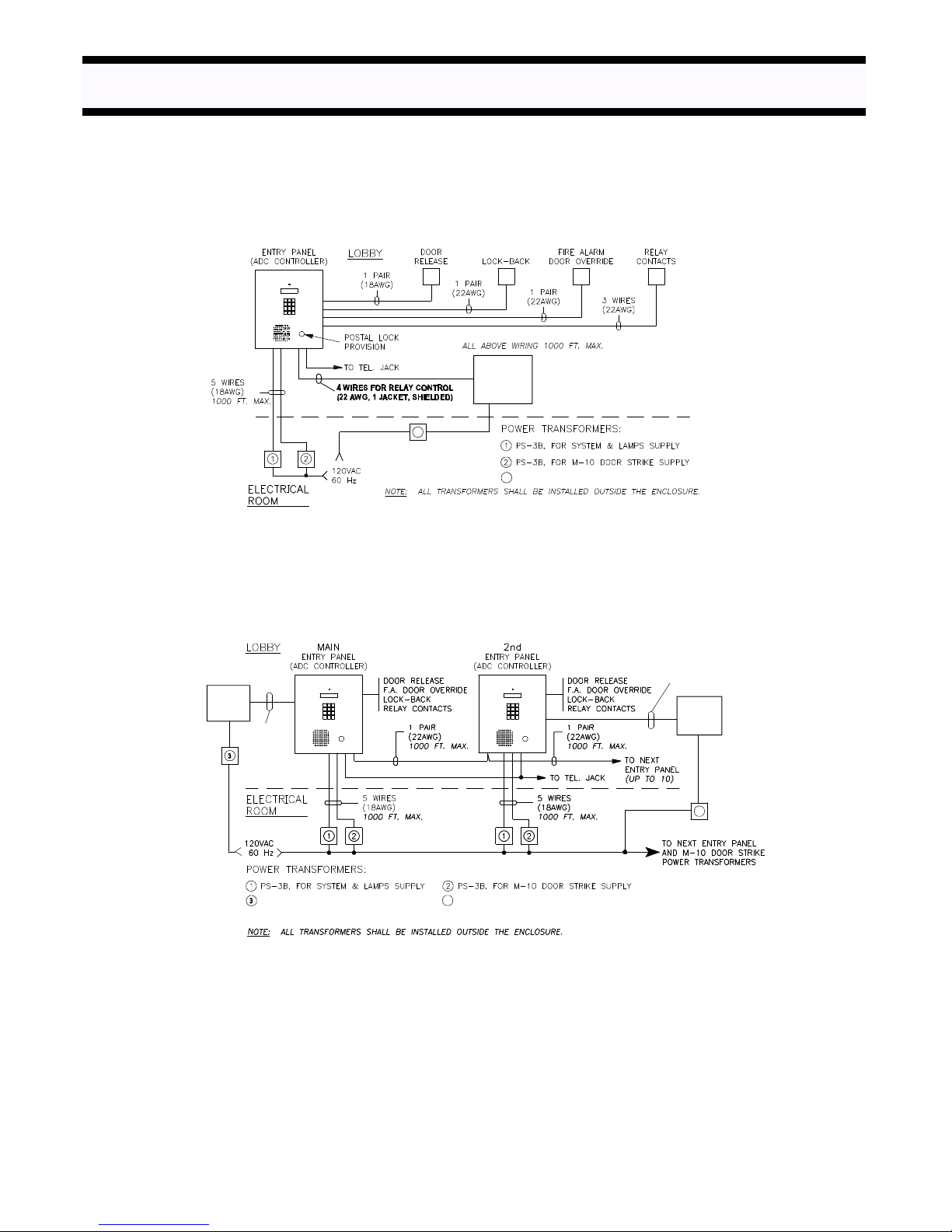
SYSTEM BLOCK DIAGRAMS
SINGLE ENTRANCE APPLICATION:
9508
Elevator
Recall
Relays
3
3 PS-3B FOR ELEVATOR RECALL RELAY CABINET
MULTIPLE ENTRANCES APPLICATION:
Optional
9508
Elevator
Recall
See
Note A
PS-3B, FOR ELEVATOR RECALL RELAYS
NOTE A: 4 WIRES FOR RELAY CONTROL (22 AWG, 1 JACKET, SHIELDED)
PS-3B, FOR ELEVATOR RECALL RELAYS
4
See Note A
Optional
9508
Elevator
Recall
4
MIRCOM TECHNOLOGIES LIMITED, ADC Series: Autodialer Telephone Access Systems Page 4
Page 7

PRE-INSTALLATION PLANNING
Before the actual installation begins, the system requires various items to be prearranged and are described below:
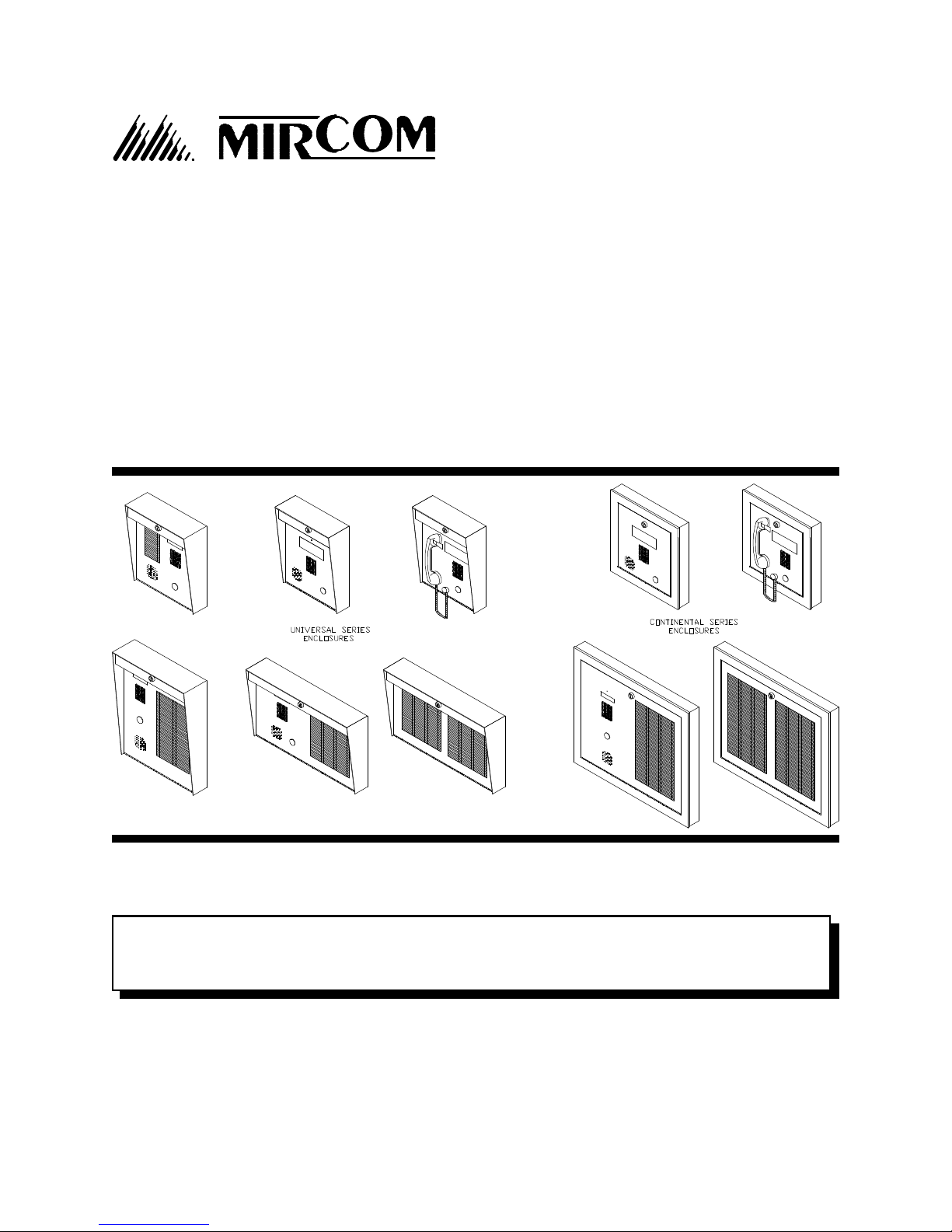
1. ENTRY OR LOBBY PANEL TYPES
The UNIVERSAL series entry/lobby panels are hooded surface mount enclosures with built-in lighting for outdoor
or indoor applications. Optional flush trim rings are available for semi-flush installations. There are eight (8) models
available and are listed below:
Universal Panels for Scrolling Directory:
Model MUS-5000SV ± Stainless Steel finish entry panel comes with keypad, 4x20 VFD
display, microphone, speaker, and micro switch for postal lock. No
controller.
Model MUS-5000SHV ± Stainless Steel finish entry panel comes with keypad, 4x20 VFD
display, armoured handset, and micro switch for postal lock. No
controller.
Universal Panels for Non-Scrolling Directory:
Model MUS-5000 ± Stainless Steel finish entry panel comes with keypad, 2x16 LCD
display, microphone, speaker, and micro switch for postal lock. No
directory and controller.
Model MUS-5000H ± Stainless Steel finish entry panel comes with keypad, 2x16 LCD
display, handset, and micro switch for postal lock. No directory and
controller.
Model MUS-5024 ± Stainless Steel finish entry panel comes with keypad, 2x16 LCD
display, microphone, speaker, micro switch for postal lock, and paper
directory for 24 names. No controller.
Model MUS-5120 ± Stainless Steel finish entry panel comes with keypad, 2x16 LCD
display, microphone, speaker, micro switch for postal lock, and paper
directory for 120 names. No controller.
Model MUS-5120H ± Stainless Steel finish entry panel comes with keypad, 2x16 LCD
display, handset, micro switch for postal lock and paper directory for
120 names. No controller.
Model MUS-5120V ± Stainless Steel finish Vertical (slim) entry panel comes with keypad,
2x16 LCD display, microphone, speaker, micro switch for postal lock,
and paper directory for 120 names. No controller.
Accessories:
Model MUFT-5000P ± Flush trim ring for MUS-5000/H/S/SH and MUS-5024 panels. Painted
black (textured).
Model MUFT-5120P ± Flush trim ring for MUS-5120/H, and MPD-5240 panels. Painted
black (textured).
Model MUFT-5120VP ± Flush trim ring for MUS-5120V panel. Painted black (textured).
Model MPD-5120 ± Stainless Steel add-on paper directory panel, 120 names capacity.
Model MPD-5240 ± Stainless Steel add-on paper directory panel, 240 names capacity.
Model MLK-040 ± Magnetic strips directory kit, 40 names capacity. It comes with plastic
letters, magnetic strips, brackets, and hexnuts.
Model TH-101 ± Thermostat heater.
Note: Painted Silver, Gold & Copper Vein lobby panels are available by custom order.
MIRCOM TECHNOLOGIES LIMITED, ADC Series: Autodialer Telephone Access Systems Page 5
Page 8

The CONTINENTAL series entry/lobby panels are designed for indoor applications only. These elegant lobby panels
can be mounted either flush or surfaced by selecting the appropriate backbox. There are six (6) models available
and are listed below:
Continental Panels for Scrolling Directory:
Model MCS-6001SV ± Stainless Steel finish entry panel comes with keypad, 4x20 VFD
display, microphone, speaker, and micro switch for postal lock. No
controller.
Model MCS-6001SHV ± Stainless Steel finish entry panel comes with keypad, 4x20 VFD
display, armoured handset, and micro switch for postal lock. No
controller.
Continental Panels for Non-Scrolling Directory:
Model MCS-6000 ± Stainless Steel finish entry panel comes with keypad, 2x16 LCD
display, microphone, speaker, and micro switch for postal lock. No
directory and controller.
Model MCS-6000H ± Stainless Steel finish entry panel comes with keypad, 2x16 LCD
display, handset, and micro switch for postal lock. No directory and
controller.
Model MCS-6240 ± Stainless Steel finish entry panel comes with keypad, 2x16 LCD display,
microphone, speaker, micro switch for postal lock, and paper
directory for 240 names. No controller.
Model MCS-6240H ± Stainless Steel finish entry panel comes with keypad, 2x16 LCD display,
handset, micro switch for postal lock and paper directory for 240
names. No controller.
Accessories:
Model MPD-6240 ± Add-on paper directory panel, 240 names capacity.
Model MPD-6480 ± Add-on paper directory panel, 480 names capacity.
Model BBF-6001 ± Flush backbox for MCS-6001S/SH. Satin coat finish.
Model BBS-6003 ± Surface backbox for MCS-6001S/SH. Painted black (textured).
Model BBF-6101 ± Flush backbox for MCS-6000, MCS-6000H, and MPD-6120 panels.
Model BBF-6102 ± Flush backbox for MCS-6240, MCS-6240H, and MPD-6480 panels.
Model BBS-6301 ± Surface backbox for MCS-6000, MCS-6000H, and MPD-6240.
Model BBS-6302 ± Surface backbox for MCS-6240, MCS-6240H, and MPD-6480
panels.
Model MLK-070 ± Magnetic strip directory kit, 70 names capacity. It comes with plastic
letters, magnetic strips, brackets, and hexnuts.
Note: Painted Silver, Gold & Copper Vein lobby panels are available by custom order.
2. CONTROLLERS
SCROLLING DIRECTORY CONTROLLERS: For both LCD and VFD Display
Model ADC-0040SDA ± Autodialer Telephone Access Controller, 40 Residents capacity.
Model ADC-0120SDA ± Autodialer Telephone Access Controller, 120 Residents capacity.
Model ADC-0360SDA ± Autodialer Telephone Access Controller, 360 Residents capacity.
Model ADC-0800SDA ± Autodialer Telephone Access Controller, 800 Residents capacity.
Optional Programming Software Kit:
Model RS-485IMK consists of MirSoft TAS programming software, RS-485 interface module, and cable is an
optional programming kit to enable the user to upload or download Residents’ names, dial codes, keyless entry
codes, and relay line numbers using a personal computer. This software can be used on IBM
PC/XT/286/386/486/Pentium Compatible PC under MS-DOS version 5 or higher, Windows 95 or higher, OS/2
with Colour or Monochrome Text Screen (MDA, CGA, EGA, VGA, SVGA) capability and one serial port. To order
this kit, please consult our factory for further information.
MIRCOM TECHNOLOGIES LIMITED, ADC Series: Autodialer Telephone Access Systems Page 6
®
® ® ®
Page 9

NON-SCROLLING DIRECTORY CONTROLLERS:
Model ADC-0040A ± Autodialer Telephone Access Controller, 40 Residents capacity.
Model ADC-0120A ± Autodialer Telephone Access Controller, 120 Residents capacity.
Model ADC-0360A ± Autodialer Telephone Access Controller, 360 Residents capacity.
Model ADC-0960A ± Autodialer Telephone Access Controller, 960 Residents capacity.
Note: Please see page 4 for System Block Diagram for more information.
3. SYSTEM & DOOR RELEASE POWER REQUIREMENTS
A single Mircom's PS-3B (Tri-Volt) power transformer is required to power the unit and lamps. A second power
transformer is required to operate the door release. Please note that the transformer and the door release must be
compatible. When using Mircom's M-10 door strike, a compatible PS-3B power transformer with 8VAC tapped is used
to power the door strike. If using an equivalent door release, the maximum strike load that may be switched through
the control unit is 28 VAC or DC, 3 Amp. maximum.
Below are the available power supplies and door strikes:
Model PS-2 ± 16 VAC / 20 VA, CSA approved Class 2 Power Transformer.
Model PS-4 ± 16 VAC / 40 VA, CSA approved Class 2 Power Transformer.
Model PS-3B ± 8 VAC /13 VA, 16 VAC /17 VA, 24 VAC /20 VA, CSA approved
Class 2 Power Transformer.
Model SPS-600W ± 600 Watts Standby Battery Supply.
Model M-10 ± DC (silent) or AC (buzzing) Door Strike. Use PS-3B transformer.
Model M-10HD ± AC (buzzing) Heavy Duty Door Strike. Use PS-3B transformer.
Model M-20 ± DC (silent) or AC (buzzing) Heavy Duty Door Strike. Use PS-3B transformer.
Important note: The door strike must have its own separate power transformer. Do not tap or use the
system power transformer.
Notes: Please see appendix "A", page 43 for specifications.
Please see page 4 for System Block Diagram for more information.
4. SITE SELECTION
Install the Entry Panel as near as possible to the controlled entry point. Do not install the system to a location where
the LCD display is exposed to direct sunlight since it will degrade the visibility.
5. TELEPHONE LINE
A Pulse (rotary) or Touch-Tone (DTMF) dedicated telephone line is required for single or multiple entrances
configuration. If possible, have the jack installed inside the control unit enclosure. Provide the following information
to phone company when ordering a telephone line:
Industry Canada (formerly D.O.C.) Registration Number: 1156 6662 A
F.C.C. Registration Number: 1M8CAN-22412-OT-E
6. WIRING REQUIREMENTS
Count the number of wires and identify the proper gauges that are required for your system configuration. For typical
Single or Multiple entrances applications, please refer to page 4 for System Block Diagram. For custom applications,
we recommend to consult our Engineering Field Support Personnel for evaluation.
7. POST OFFICE LOCK
The system has a built-in micro switch and mounting hardware for postal lock installation. If a postal service is
required, contact the Post Office to obtain the lock.
MIRCOM TECHNOLOGIES LIMITED, ADC Series: Autodialer Telephone Access Systems Page 7
Page 10
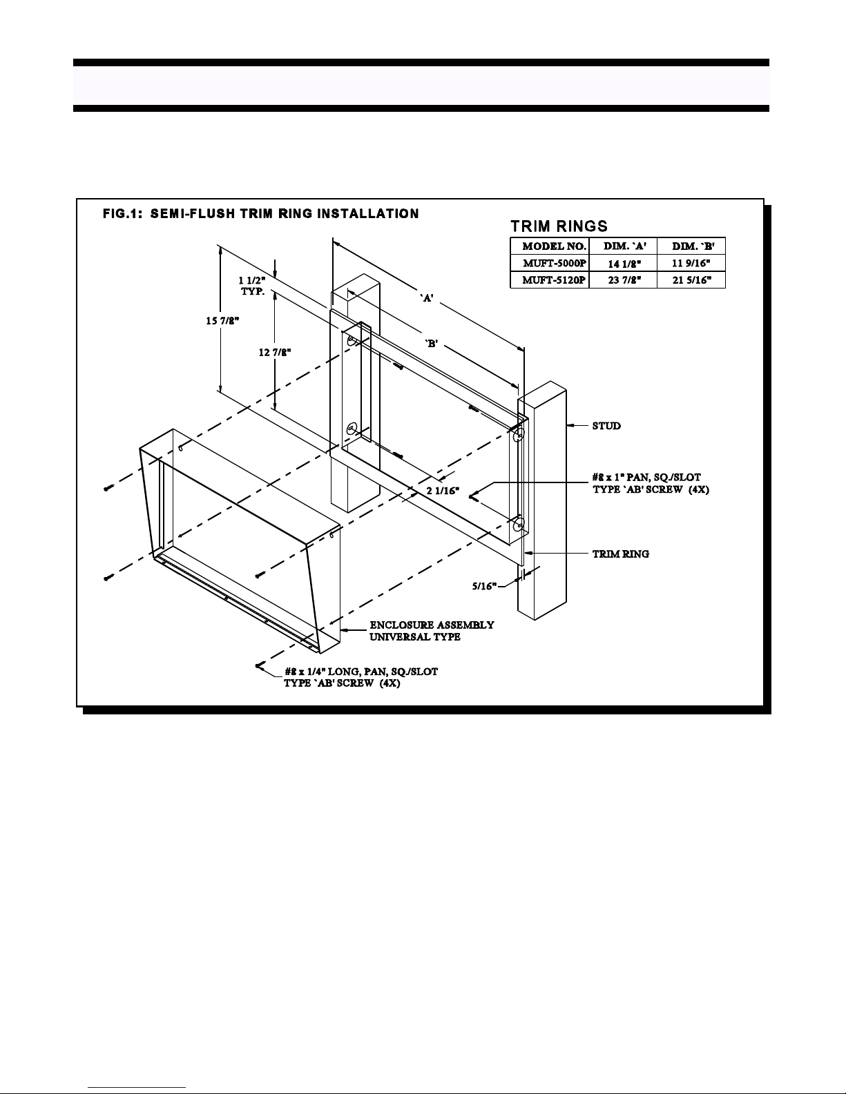
ENCLOSURES AND ACCESSORIES INSTALLATION INSTRUCTIONS
MOUNTING THE UNIVERSAL TYPE LOBBY/ENTRY PANEL
Mount the panel as shown in FIG.1, FIG.2, and FIG. 2A using the supplied screws.
MIRCOM TECHNOLOGIES LIMITED, ADC Series: Autodialer Telephone Access Systems Page 8
Page 11
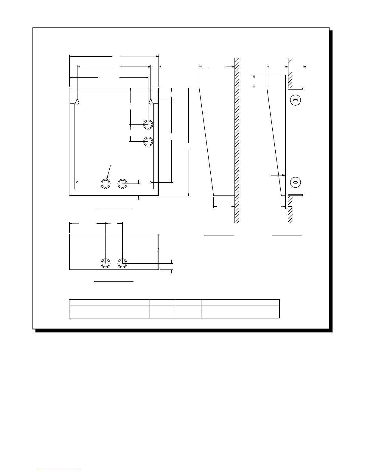
FIG. 2: PANEL INSTALLATION
`A'
4 1/2"
`B' 15/16"
9 11/16"
4 5/16"
2"
7/8" & 1 1/8"
KNOCKOUTS (6X)
1 7/16"
FRONT VIEW
2"
1 7/16"
9 11/16"
12 3/4"
4 3/16"
1 9/16"
2 1/2" 5/16"
WALL
(SURFACE)
FLUSH
TRIM
RING
2 1/2"
SIDE VIEWSIDE VIEW
(SEMI-FLUSH)
1 3/4"
WALL
BOTTOM VIEW
MODEL NO.
MUS-5000/H/S/SH, MUS-5024,MPD-5120
MUS-5120, MUS-5120H, MPD-5240
DIM. `A'
11"
20 3/4"
3/4"
DIM. `B'
9 3/16"
18 15/16"
SEMI-FLUSH TRIM RING IF REQUIRED
MODEL MUFT-5000P
MODEL MUFT-5120P
MIRCOM TECHNOLOGIES LIMITED, ADC Series: Autodialer Telephone Access Systems Page 9
Page 12
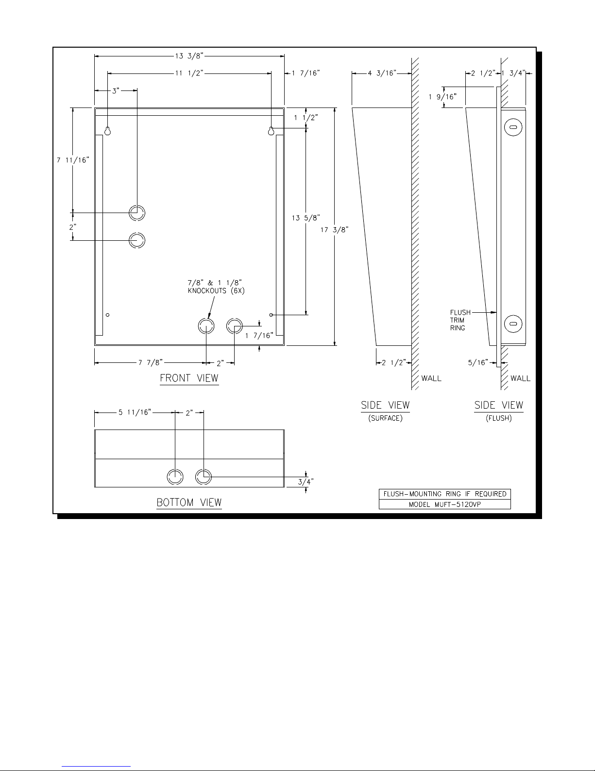
FIG.2A: MUS-5120V (Slim Vertical) PANEL INSTALLATION
MOUNTING THE MAGNETIC LETTER KIT MODEL MLK-040 (OPTIONAL)
Mount the Magnetic Letter Kit according to the Installation Instruction (LT-460) that comes with the Kit. Extra
characters and magnetic strips can be ordered separately. Please contact the factory or our nearest dealer.
MIRCOM TECHNOLOGIES LIMITED, ADC Series: Autodialer Telephone Access Systems Page 10
Page 13

MOUNTING THE THERMOSTAT HEATER KIT MODEL TH-101 (OPTIONAL)
Mount the Heater Kit according to the Fig 2B. Install the TH-101 Heater into bottom left hand corner of the universal
enclosure using the two spacers and two hex nuts provided. Use a pair of #18 AWG wires to connect from the TH101 unit to 24VAC tap on the PS-3B transformer. The transformer must be installed outside the enclosure.
Fig. 2B HEATER INSTALLATION
MIRCOM TECHNOLOGIES LIMITED, ADC Series: Autodialer Telephone Access Systems Page 11
Page 14

MOUNTING THE CONTINENTAL TYPE LOBBY/ENTRY PANEL
Mount the panels as shown in FIG.3 (for scrolling) or FIG.3A (for non-scrolling) using the supplied screws.
FIG. 3: SCROLLING DIRECTORY PANELS
5 15/16"
BOTTOM VIEW
2"
(SURFACE)
BOTTOM VIEW
(FLUSH)
DOOR FRAME FOR
MCS-6001S , MCS-6001SH
1"
BACKBOX (SURFACE)
BACKBOX
1 5/16"
1"
BACKBOX
SIDE VIEW
(SURFACE)
BBS-6003
BACKBOX (FLUSH)
BBF-6001
WIDTH
13 11/16"
WIDTH
11 1/4"
SIDE VIEW
HEIGHT
15 9/16"
HEIGHT
13 13/16"
(FLUSH)
DEPTH
2 3/16"
DEPTH
2 3/16"
MIRCOM TECHNOLOGIES LIMITED, ADC Series: Autodialer Telephone Access Systems Page 12
Page 15

FIG. 3A: NON-SCROLLING DIRECTORY PANELS
`A'
`B'
(DOOR NOT SHOWN)
7/8" & 1 1/8"
KNOCKOUTS (4X)
FRONT VIEW
5 15/16"
2"
4 1/8"
DOOR FRAME
2 3/8"
1 7/16"
15 5/8"
20 1/2"
2 1/4" 2 3/16"
5/16"
20 5/16"
WALL WALL
SIDE VIEW
(SURFACE)
18 1/2"
1"
SIDE VIEW
(FLUSH)
BOTTOM VIEW
(SURFACE)
BOTTOM VIEW
(FLUSH)
BACKBOX
1 5/16"
1"
BACKBOX
1"
BACKBOX (SURFACE)
BBS-6301
BBS-6302
BACKBOX (FLUSH)
BBF-6101
BBF-6102
PANEL MODEL NO.
MCS-6000, MCS-6000H, MPD-6240
MCS-6240, MCS-6240H, MPD-6480 23 5/8"
WIDTH
13 11/16"
23 7/16"
WIDTH
11 1/4"
21"
HEIGHT
20 5/16"
20 5/16"
HEIGHT
18 1/2"
18 1/2"
DIM. `A'
13 7/8"
DEPTH
2 3/16"
2 3/16"
DEPTH
2 3/16"
2 3/16"
DIM. `B'
9 3/16"
18 15/16"
MOUNTING THE MAGNETIC LETTER KIT MLK-070 (OPTIONAL)
Mount the Magnetic Letter Kit according to the Installation Instruction (LT-460) that comes with the Kit. This kit is
used only for Continental type lobby/entry panel.
MIRCOM TECHNOLOGIES LIMITED, ADC Series: Autodialer Telephone Access Systems Page 13
Page 16
SYSTEM WIRING INSTRUCTIONS
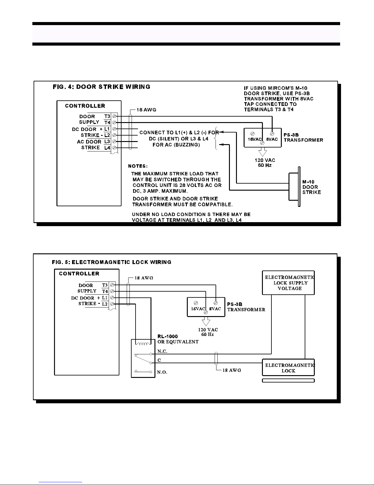
WIRING THE DOOR STRIKE
Wire the Door Strike as shown in FIG.4.
WIRING THE ELECTROMAGNETIC DOOR LOCK
Wire as shown in FIG. 5.
MIRCOM TECHNOLOGIES LIMITED, ADC Series: Autodialer Telephone Access Systems Page 14
Page 17
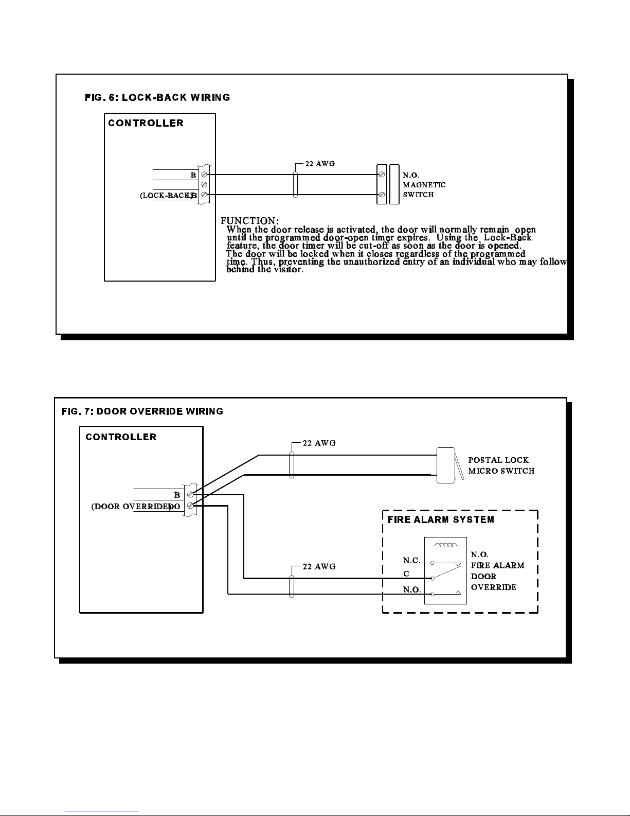
WIRING THE LOCK-BACK SWITCH
Wire the Lock-Back Switch as shown in FIG. 6 to enable automatic door-open timer cut-off.
WIRING THE DOOR OVERRIDE (Postal Lock & Fire Alarm)
Wire as shown on FIG.7.
MIRCOM TECHNOLOGIES LIMITED, ADC Series: Autodialer Telephone Access Systems Page 15
Page 18
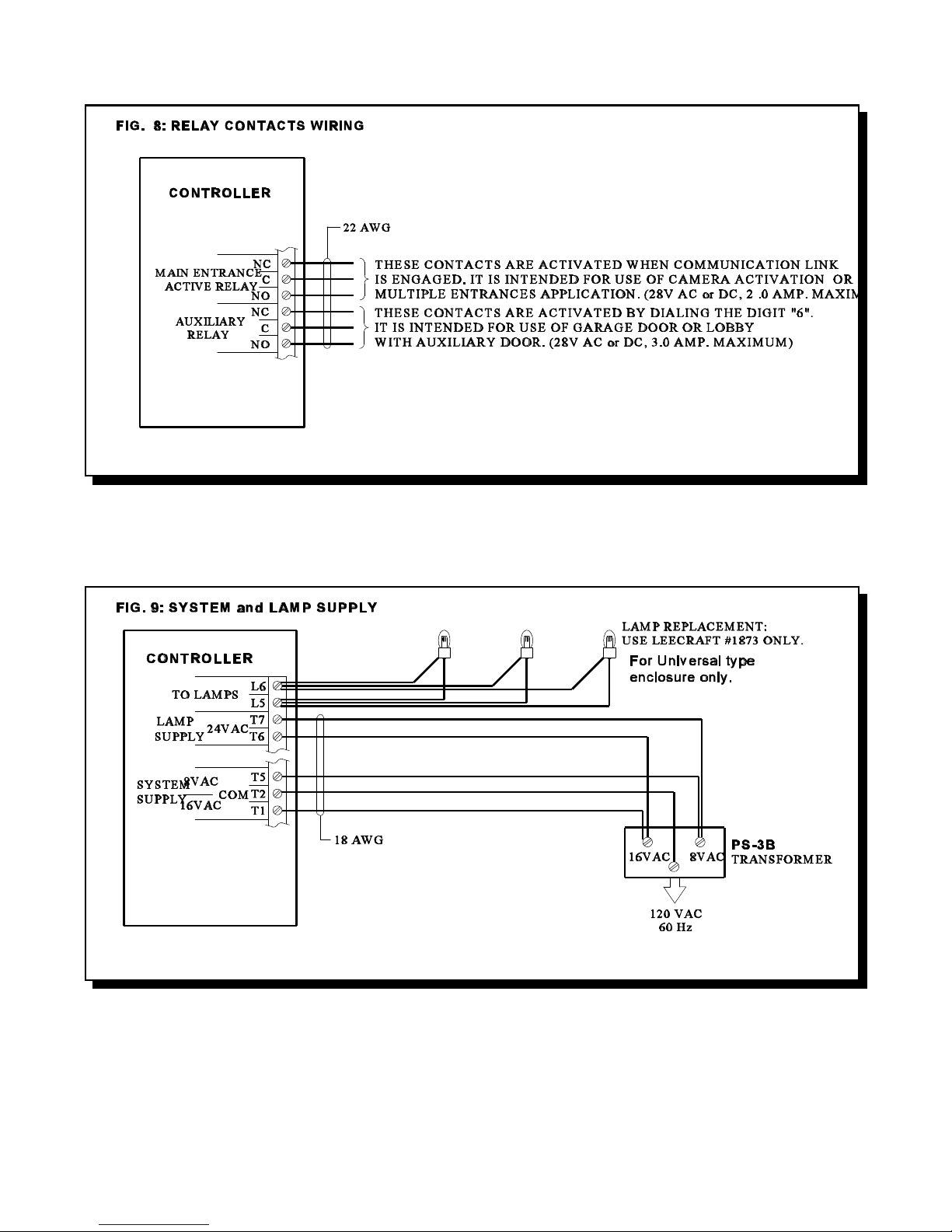
WIRING THE AUXILIARY RELAY and MAIN ENTRANCE ACTIVE RELAY CONTACTS
Wire as shown in FIG.8.
WIRING THE SYSTEM and LAMP SUPPLIES
Wire as shown in FIG. 9.
MIRCOM TECHNOLOGIES LIMITED, ADC Series: Autodialer Telephone Access Systems Page 16
Page 19

WIRING THE SPEAKER, MIC., and KEYPAD/DISPLAY ASSEMBLY
FIG. 10: SPK., MIC., KEYPAD/DISPLAY ASSEMBLY WIRING
CONTROLLER
BLACK & SHIELD
RED
WHITE
GREEN
RIBBON CABLE
MIC.
45 OHM
SPEAKER
M2
M1-+
S2
S1
20 pins header
MULTIPLE ENTRANCES and TELEPHONE LINE WIRING
FIG.11: MULTIPLE ENTRANCES and ONE TELEPHONE LINE WIRING
TO FRONT DOOR
KEYPAD/DISPLAY
ASSEMBLY
WIRING THE EARTH GROUND - IMPORTANT NOTICE:
Although the electronics of the ADC Series are not Earth Grounded, it is absolutely vital to have good solid Earth Grounding connections to each
enclosure; that is, a ground bonding wire (preferably at least 14 AWG) that is run to the NEAREST confirmed building electrical system ground, or cold
water pipe. Newer enclosures will have a clearly marked screw connection on the back marked “CHASSIS GROUND”. Older enclosures may be Earth
Grounded via a mounting screw if the enclosure metal under the screw is sanded clean of paint to ensure a good electrical connection.
NOTE: IF PROPER GROUNDING REQUIREMENTS ARE NOT FOLLOWED AS OUTLINED, REPAIRS MAY NOT BE
COVERED BY WARRANTY.
POWERING THE SYSTEM
Before powering the system, double check all the connections. When all connections are checked, power the system up and observe the system display.
If necessary, adjust the contrast as described on Display Contrast Adjustment section.
MIRCOM TECHNOLOGIES LIMITED, ADC Series: Autodialer Telephone Access Systems Page 17
Page 20

ELEVATOR-RECALL(RESTRICTION) FEATURE
GENERAL OPERATION
Elevator-Recall(Restriction) is now a standard feature which has been implemented in the ADC Series system for
software version 3.0 and up. The feature operates as such: a visitor calls a resident, is then allowed entrance at
which point the entry door is opened and the floor relay is activated. When the visitor gets on the elevator, he can
only access the floor of the resident. This feature is supported from both the Lobby as well as remote door points-ofaccess. The feature operates by allowing the installer to (directly) associate the first two digits of the Resident/Tenant
Code which a visitor would enter on the lobby keypad (i.e. when trying to call a Resident Suite), with an elevator
recall(restriction) relay number. This reserved relay will be activated only after a Resident makes the decision to
allow the visitor access to the building (i.e. when the Resident presses the digit which has been programmed to
activate the main/remote door latch), so that the main/remote door latch and elevator recall relay are activated at
the same time and for the same length of time. We suggest a separate timer be used for each elevator floor relay.
Note: In order to have the Elevator-Recall (Restriction) function, a relay cabinet (with Model 9512E Elevator-Recall
Relay Cards installed) is required and it must be jumpered in the 16th position as shown in Fig. 11A.
The first two digits of the Resident/Tenant Code allow for a range from 01-95 relays to be reserved for this purpose.
The relay cabinet has space for 8 cards, each card containing 12 relays. The very last relay in this cabinet is however
NOT available, as it is always reserved for use by the ADC system. Thus relays 1 to 95 are available for ElevatorRecall (Restriction).
As an example, take the two Resident/Tenant codes “1201" and “1215", both these codes would activate the same
reserved relay number 12. For the purposes of the Elevator-Recall (Restriction) functionality, it is assumed that both
Resident/Tenant Codes (i.e. 1201 and 1215) would be assigned to Residents on the same (i.e. 12th) floor. Thus,
a maximum of 95 possible relays (each assigned to a separate floor) can be accessed in this manner.
MIRCOM TECHNOLOGIES LIMITED, ADC Series: Autodialer Telephone Access Systems Page 18
Page 21

Elevator-Recall (Restriction) is available with single and multiple entrances and is programmed accordingly.
1. SINGLE ENTRANCE - ELEVATOR-RECALL
At the ADC controller the relays are programmed to activate in association with a specific Resident/Tenant Code.
Elevator-Recall (Restriction) relays are available as the relays in the relay cabinet designated as sixteen.
For example: A single entrance system consists of an ADC Controller and one relay cabinet. This relay cabinet is
used as Elevator-Recall (Restriction) relays (the motherboard is jumpered as shown in Figure 11A). Therefore it is
necessary to associate all residents on the same floor with one Elevator-Recall (Restriction) relay. Sample
programming at the ADC Controller would be as such:
Resident/Tenant Code Elevator-Recall Relay
1201 12
1202 12
1203 12
1301 13
Looking at the information above the first two digits of the Resident/Tenant Code represents the resident’s floor and
the relay. Therefore all residents on the twelfth floor activate the same Elevator-Recall (Restriction) relay (relay
number 12 on the first relay card).
2. MULTIPLE ENTRANCES - ELEVATOR RECALL
For systems with more than one entrance, each ADC Controller must be programmed for the Elevator-Recall
(Restriction) application separately. Each ADC Controller requires its own set of relays.
EXAMPLE:
When a Resident/Tenant Code of “1205" is entered on the ADC keypad at the entrance, then the Elevator Recall
(Restriction) relay number 12 (twelfth relay on card number 1) will be activated. If the Resident/Code is 1822, then
relay number 18 (sixth relay on card number 2) will be activated. The relay numbering scheme is tabled below.
9512E ELEVATOR-RECALL RELAY CARDS IN
A 9508 RELAY CABINET
Relay Card Number 1 (Relay number 1 to 12)
Relay Card Number 2 (Relay number 13 to 24)
Relay Card Number 3 (Relay number 25 to 36)
Relay Card Number 4 (Relay number 37 to 48)
Relay Card Number 5 (Relay number 49 to 60)
Relay Card Number 6 (Relay number 61 to 72)
Relay Card Number 7 (Relay number 73 to 84)
Relay Card Number 8 (Relay number 85 to 95)
LAST RELAY NOT USED
NOTE: FIRST TWO DIGITS OF THE RESIDENT/TENANT CODE REPRESENTS THE ELEVATOR- RECALL
RELAY NUMBER.
WHEN USING ELEVATOR-RECALL (RESTRICTION) IT IS NECESSARY TO USE A SEPARATE
TIMER FOR EACH OF THE FLOOR RELAYS.
MIRCOM TECHNOLOGIES LIMITED, ADC Series: Autodialer Telephone Access Systems Page 19
Page 22

WIRING THE 9512E ELEVATOR-RECALL RELAY CARD
The 9512E Elevator-Recall Relay Card provides Common (C) and Normally Open (NC) contacts marked on the
board silkscreen. The very first relay marked Aux Rly is an auxiliary relay which is activated any time another relay
on the board is activated. The relays available for Elevator-Recall (Restriction) are labelled Relay 1 to Relay 12.
Wiring is achieved at the terminal block which is removable for easy installation.
The following diagram shows the wiring between the ADC Controller and the Elevator Restriction (Recall) Relay
Cabinet motherboard.
MIRCOM TECHNOLOGIES LIMITED, ADC Series: Autodialer Telephone Access Systems Page 20
Page 23

PROGRAMMING INSTRUCTIONS: SCROLLING DIRECTORY
Before programming the system, obtain the required information by using the form provided in Appendix “B”.
After the system initializations (power up), the display should appear as shown below.
< MIRCOM >
Enter tenant code or
to view directory,
press * UP # DOWN
This is the Normal Mode of the system. The system will accept all valid Access Codes entered directly on the
keypad. Use the * or # key to scroll "up or down" the directory list. Pressing the * or # key momentarily will scroll "up
or down" the list one name at a time. Holding the * or # key will scroll "up or down" continuously and stop scrolling
when the key is released.
Before entering the Programming Mode for the first time, it is recommended to restore the factory default Master
Code *999 by shorting the reset pins for approximately 3 seconds. Please refer to Fig. 12 for the location of the reset
pins. Note: Shorting the reset pins will only restore the factory default Master Code *999 and will not affect any
programmed information.
ENTERING PROGRAMMING MODE
While at Normal Mode, press "0" then enter the MASTER CODE (factory default is *999) to enable PROGRAMMING
MODE.
Pressing "0", the screen should appear ...
< MIRCOM >
***** _ _ _ _ *****
*******************
-Keyless Entry Mode-
Pressing "*", the next screen should appear...
< MIRCOM >
***** * _ _ _ *****
*******************
-Program Code Entry-
Enter Master Code (default is 999), the next screen should appear...
< MIRCOM >
PROGRAM MODE
-Please Wait-
-Program Code Entry-
for a few seconds then the screen should change to...
<<< PROGRAM MODE >>>
Enter the three
digit program code
[Use *888 for Menu]
This is the PROGRAM MODE menu. At this stage, the system is waiting for valid programming code.
Important note:
Before programming the system for the first time, it is recommended to clear-up all memories and restore all factory defaults by using a special
command *5*5 while at Program Mode menu . Since this special command (*5*5) is a destructive command which can erase all the programmed
information without the provision to undo, the user must take a precaution when using this command.
MIRCOM TECHNOLOGIES LIMITED, ADC Series: Autodialer Telephone Access Systems Page 21
Page 24

There are two ways to program the system.
1. By using *888 for Menu Driven type of programming.
2. By using the Direct Access Programming Codes for manual programming. Entering these codes will lead the user
directly to the desired function. The Direct Access Programming Codes are listed on the table below.
Code Function Factory Default Program Choices
*000 Exit Programming Mode *000 n/a NONE
*101 Enter Residents Dial Codes and Blank See worksheet 4 digit resident
Telephone Numbers code plus up to 8
digit telephone
number
*202 Review, Edit,Delete Codes & Blank See worksheet Up to 11 digits to
Names review or delete
*222 Enter Prefix (0) 0905 See worksheet 0-9 for the first
digit and up to 4
digits for area
code
*303 Enter Keyless Entry Codes Blank See worksheet 4 digits
*333 Quit Feature using the “#” key 11 __ __ 00 Press # key
once or
11 Press # key
twice (2 digits)
*404 Review , Delete Keyless Entry Blank See worksheet 4 digit code to
Codes review or delete
*444 Program On Line Timer for Minutes 00 __ __ 00 Seconds or
or Seconds 11Minutes (2
digits)
*505 Change Master Code *999 *__ __ __ 3 digits
*606 Select Pulse (Rotary) or Tone 11 Tone ___ ___ 00 Pulse or
(DTMF) 11 Tone (2 digits)
*707 Set Door Open Timer 10 seconds __ __ 00 to 99 seconds
seconds (2 digits)
*808 Set On Line Timer 60 seconds __ __ 00 to 99 (2 digits)
*909 Select MULTIPLE/SINGLE Entrance Single (11) __ __ 11 Single or
00 Multi (2 digits)
MIRCOM TECHNOLOGIES LIMITED, ADC Series: Autodialer Telephone Access Systems Page 22
Page 25

"NO MANUAL" MENU DRIVEN PROGRAMMING USING *888
While at programming mode, enter the "*888" to gain access to programming menu.
After entering the *888, the screen should appear...
[1=Bck] [3=Fwd]
Welcome to the ADC
On-Line Help Menu!
[*=Abort] [#=Yes]
1 and 3 keys are for scrolling backward or forward the feature menus.
# to access the displayed feature.
* to quit, exit, cancel, or abort.
Press 3 for next menu. The screen should appear...
[1=Bck] [3=Fwd]
Do you want to exit
from PROGRAM Mode?
[*=Abort] [#=Yes]
1 inactive key
3 key to the first feature menu.
# key to exit to Normal Mode.
* key to Programming Mode menu
NOTE: Repeat the above process to locate the desired feature.
To exit to Normal Mode, enter *000 while at PROGRAM MODE menu.
Press 3 again to first feature menu.
RESIDENTS’/TENANTS’ DIAL CODE and TELEPHONE NUMBER ENTRY
Residents'/Tenants’ Dial Codes can be entered in the format of 1, 2, 3, or 4 digits (less than 4 digits must be preceded
by 0's). These codes are used to call the Residents using the Entry Panel's keypad. The corresponding “telephone
number” for each dial code is set to 7-digits by default. ADC units will allow the user to define telephone numbers
up to 11-digits with 10 user definable 4-digit “Area Code” prefixes.
CAUTION! Before programming the system, the user must determine the maximum telephone number digit
length. Reformatting the telephone digit length will erase those programmed Dial Codes and
Telephone Numbers.
SETTING THE TELEPHONE NUMBER DIGIT LENGTH:
Scroll through until you reach the feature as shown below.
[1=Bck] [3=Fwd]
Do you want to edit
Max. Digit/Listing?
[*=Abort] [#=Yes]
MIRCOM TECHNOLOGIES LIMITED, ADC Series: Autodialer Telephone Access Systems Page 23
Page 26

Press # to access the feature. The display should appear...
-Program OptionsEnter size as
07, 08 or 11 = _ _
Please enter choice:
Select: 07 for seven digits telephone numbers (factory default),
08 for eight digits telephone numbers, or
11 for eleven digits telephone numbers
* to abort entry and exit to PROGRAM MODE menu.
NOTE: When selecting 11digits, the user must use the 4-digit “Area Code” prefix to form up to an 11 digit telephone
number. There are ten user definable prefixes that can be assigned. Factory default for all the prefixes are
set to 0905. To assign a new prefix #, follow the instructions described under “TO CHANGE PREFIX
CODES” section below. Prefix numbers are not required for 7 or 8 digit telephone numbers.
After entering the choice for maximum digits per listing, the screen should change to...
-Program Options-
#=Store, *=Abort
07, 08 or 11 = x x
Please enter choice:
Press # to store or * to abort entry.
To quit, enter *000 while at PROGRAM MODE menu.
TO CHANGE THE PREFIX CODES:
To change the Prefix Codes, scroll through until you reach the feature as shown below.
[1=Bck] [3=Fwd]
Do you want to edit
Code and Prefix #?
[*=Abort] [#=Yes]
Press # to access the feature. The display should change to...
-Program OptionsCode Prefix # For Code: enter any number from 0 to 9
( _ ) _ _ _ _ For Prefix #: enter up to 4-digit “Area Code”
Please enter choice:
Where: “Code” (from 0 to 9) is used to call up the corresponding Prefix number.
“Prefix #” (up to 4 digits) is used for “Area Code” number that can be used with standard
7-digits telephone number to form up to 11 digits. Factory defaults for all 10 Prefixes are 0905.
Unused prefix digit(s) can be blanked-out by pressing the “#” key.
After entering the desired Code and Prefix #, the next screen should be...
-Program Options#=Store *=Abort
( x ) x x x x
Please enter choice:
Press # to store or * to abort entry. Repeat this process to edit or to assign new prefix numbers.
To exit to Normal Mode, enter *000 while at the PROGRAM MODE menu.
MIRCOM TECHNOLOGIES LIMITED, ADC Series: Autodialer Telephone Access Systems Page 24
Page 27

ENTERING RESIDENTS’/TENANTS’ CODES AND TELEPHONE NUMBERS:
To enter codes and telephone numbers, scroll through until you reach the feature as shown below.
[1=Bck] [3=Fwd]
Do you want to enter
TENANT Codes?
[*=Abort] [#=Yes]
Press # to access the feature. The screen should change according to the digit length chosen. Below are the possible
screens.
7 digits telephone # (default) 8 digits telephone # 11 digits telephone #
-Program Options- -Program Options- -Program OptionsCode Telephone Code Telephone Code Telephone
____ ___-____ ____ ___-____ ____ ___-____
Please enter choice: Please enter choice: Please enter choice:
Enter up to 7-digit Enter up to 8-digit The first digit is used
telephone number. telephone number. for prefix CODE number
assigned. The remaining
digits are used for standard
7-digit telephone number.
Enter: 000x for one (1) digit dial code
Enter: 00xx for two (2) digit dial code
Enter: 0xxx for three (3) digit dial code
Enter: xxxx for four (4) digit dial code
0 = ZERO x = RESIDENT/TENANT DIAL CODE (numeric 0 to 9)
For example: To call a resident/tenant with two digits dial codes, simply enter xx.
Press # key to blank unused telephone digits. This feature (to be able to blank out any desired digit) is particularly
useful when requiring shorter number of digits to be dialled out through a compatible private DTMF type telephone
system.
When you make a mistake and wish to reenter the Dial Code and Tel. #, press *.
After entering the Dial Code and Telephone Number, the next typical screen should display...
For 7-digits Tel.# For 8 & 11digits Tel.#
-Program Options- -Program Options#=Store, *=Abort #=Store, *=Abort
xxxx xxx-xxxx xxxx xxxx-xxxx
Please enter choice: Please enter choice:
Press # to Store or * to abort entry. Repeat this process until all dial codes and telephone numbers are entered. Press
* to return to PROGRAM MODE menu. To quit, enter *000 while at PROGRAM MODE menu to return to NORMAL
MODE.
ENTERING UP TO 11-DIGIT RESIDENTS’ TELEPHONE NUMBERS: Special Feature
As mentioned previously, the user must set the Code and Prefix number when 9 to 11-digit telephone numbers are
required. The following example will illustrate how the unit should be programmed.
MIRCOM TECHNOLOGIES LIMITED, ADC Series: Autodialer Telephone Access Systems Page 25
Page 28

Example: Ten digit telephone number is required.
Dial Code: 2863
Area Code: 905
Tel. #: 660-4655
Program the system as follows:
Set the telephone digit length to 11 as shown below.
-Program OptionsEnter size as Enter 11 to select eleven digit
07, 08 or 11 = 11 telephone number
Please enter choice:
Set the Code and prefix number.
-Program OptionsCode Prefix #
( 1 ) 905_ Press # to blank out the last (unused) digit.
Please enter choice:
Enter dial Code and Telephone number using the Code for defined Prefix # as described above.
-Program OptionsCode Telephone NOTE: The first digit of the telephone
2863 1660-4655 prefix code, in this case “1".
Please enter choice:
In normal Operating Mode, entering the Dial Code “2863" on the lobby keypad will dial 905 660 4655
through the public telephone network.
ENTER, REVIEW, EDIT or DELETE RESIDENTS’/TENANTS NAMES ON THE LIST
To enter, review, edit or delete Residents'/Tenants’ Names on the list, scroll through until you reach the feature as
shown below.
[1=Bck] [3=Fwd]
Do you want to edit
TENANT Names?
[*=Abort] [#=Yes]
Press # to access the feature. The display should appear...
====TOP-OF-LIST=====
xxxx: <== Second line with “:” displayed can
xxxx be selected by pressing “0".
xxxx Where: xxxx are the Dial Codes.
Note: Press any number to exit.
Press * or # to scroll (review) "up or down" the list . To enter, review, edit and delete the Resident’s/Tenant’s name,
scroll until the desired Access Code and Resident Name is in the second line of the display.
MIRCOM TECHNOLOGIES LIMITED, ADC Series: Autodialer Telephone Access Systems Page 26
Page 29

Press "0" to enter, edit or delete Dial Code and Resident Name. The next screen should appear....
7 digits telephone # (default) 8 &11 digits telephone #
-Program Options- -Program Options- refer to worksheet
CODE:xxxx@xxx-xxxx CODE:xxxx@xxxx-xxxx <== APPENDIX B
NAME:xxxxxxxxxxxxxxx NAME:xxxxxxxxxxxxxxx <==15 characters max.
Please enter choice: Please enter choice:
1and 3 to scroll "up or down" the character set. Character Set Table is given on Appendix C.
7and 9 to move the cursor "left or right".
# to delete the displayed Dial Code, Telephone number and Resident Name.
After entering Resident/Tenant name, press * . The next screen should appear...
-Program Options-
* = Abort, # = Store
Name:xxxxxxxxxxxxxxx
Please enter choice:
Press * to abort or # to store entry. Repeat the above process until all Residents' /Tenants’ names are entered. When
finished, press any number from 1-9 to return to the PROGRAM MODE menu. To quit, enter *000 while at the
PROGRAM MODE menu to return to NORMAL MODE.
ENTER KEYLESS ENTRY CODES
The system can provide up to 1000 Keyless Entry Codes for Residents and 5 spares for building management.
Entering any valid Keyless Codes on keypad will open the door without the necessity of calling the Resident. For
obvious reasons, keyless entry codes should be kept well guarded and controlled. ADC units will allow the user
to assign a specific code (within the given ranges) that would activate either the Main Door or Auxiliary Door relay.
The main door relay can be activated using the range from 0000 to 4999 and the auxiliary door relay can be activated
using the range from 5000 to 9999. The user is advised to program the unit using these specified ranges if such
operation is required.
[Operation: To open door, press 0 followed by the four digit Keyless Entry Code]
Scroll through until you reach the feature as shown below.
[1=Bck] [3=Fwd]
Do you want to enter
KEYLESS Codes?
[*=Abort] [#=Yes]
Press # to access the feature. The display should appear...
-Program Options-
KEYLESS Entry
Code #_ _ _ _
Please enter choice:
Enter the four digit Keyless Entry Code. If you make a mistake or wish to reenter the code, press * to enter code
again. The next display should change to...
Press # to store or * to abort entry. Repeat this process until all codes are entered.
MIRCOM TECHNOLOGIES LIMITED, ADC Series: Autodialer Telephone Access Systems Page 27
-Program Options-
#=Store, *=Abort
Code # x x x x
Please enter choice:
Page 30

Press * to exit to PROGRAM MODE menu when finished. To quit, enter *000 while at the PROGRAM MODE menu
to return to NORMAL MODE.
REVIEW AND DELETE KEYLESS ENTRY CODES
To review and delete keyless entry codes, scroll through until you reach the feature as shown below.
[1=Bck] [3=Fwd]
Do you want to edit
KEYLESS Codes?
[*=Abort] [#=Yes]
Press # to access the feature. The display should appear...
-Program Options-
Code To Review
# _ _ _ _
Please enter choice:
Enter the Keyless Entry Code to review or delete. The next display should appear...
-Program Options-
KEYLESS Entry
Code # x x x x
Please enter choice:
Press 1 or 3 to scroll up or down the list. To delete the displayed code, press #. When finished, press * to exit to the
PROGRAM MODE menu for programming other functions. To quit, enter *000 while at PROGRAM MODE menu
to return to NORMAL MODE.
REPROGRAM MASTER CODE
Master Code (factory default *999) may be changed to any desired three (3) digit code number. Since this code is
used to access all levels of programming, it would be a good idea to change the code to one that will be known only
by the installer or management personnel. Please enter the new Master Code in the space provided below for future
reference.
New Master Code: ___________________ Date: ______________________
To change the MASTER CODE, scroll through until you reach the feature as shown below.
[1=Bck] [3=Fwd]
Do you want to edit
the MASTER Code?
[*=Abort] [#=Yes]
Press # to access the feature. The display should appear...
-Program Options-
MASTER CODE
*_ _ _
Please enter choice:
Enter the New Master Code. Please do not use *888 for Master Code. The next display should appear...
MIRCOM TECHNOLOGIES LIMITED, ADC Series: Autodialer Telephone Access Systems Page 28
-Program Options-
#=Store, *=Abort
* x x x
Please enter choice:
Page 31

Press # to store or * to abort entry. After pressing the store button, the next display should appear...
-Program Options-
Press *
To exit
Please enter choice:
Press * to exit to PROGRAM MODE menu. To quit, enter *000 while at PROGRAM MODE menu to return to
NORMAL MODE.
NOTE: To restore Master Code, please see FIG. 12 for location of reset pads.
SELECT “DOOR OPEN CODE” FOR MAIN AND AUXILIARY DOORS (DTMF only)
This feature will allow the user to change the Door Open Code (DTMF only) to any desired digit from 0 to 9. This
feature is particularly useful when the default door open code for opening the Main or Auxiliary doors is falsetriggering the door strike “open” due to a “series of tones” produced by some older answering machines when it
answers a call. It is recommended to select a stable Door Open Code to improve security. These “Door Open Codes”
are used by all Residents to release the door by simply dialling the assigned digit on their telephone while on-line
with their visitors.
NOTE: The Door Open Code for pulse (rotary) type telephones is a fixed digit “9". Dialling a pulse digit “9" will
activate the main door relay. An auxiliary door relay can be activated only by a standard DTMF Code as
programmed; there is no provision for pulse activation.
To change the Door Open Code for the Main Door:
Scroll though until you reach the feature as shown below.
[1=Bck] [3=Fwd]
Do you want to edit
DTMF Code#1?
[*=Abort] [#=Yes]
Press # to access the feature. The next display screen should appear...
-Program OptionsEnter DTMF digit
to open door ( _ ) Digit “9" is the factory default.
Please enter choice:
Enter a number from 0 to 9 for code to open the main door. The next display screen should appear...
-Program Options-
#=Store, *=Abort
to open door ( x )
Please enter choice:
Press # to store or * to abort entry.
To quit, enter *000 while at the PROGRAM MODE menu to return to NORMAL MODE.
MIRCOM TECHNOLOGIES LIMITED, ADC Series: Autodialer Telephone Access Systems Page 29
Page 32

To change the Door Open Code for the Auxiliary Door:
Scroll though until you reach the feature as shown below.
[1=Bck] [3=Fwd]
Do you want to edit
DTMF Code#2?
[*=Abort] [#=Yes]
Press # to access the feature. The next display screen should appear...
-Program OptionsEnter DTMF digit
to open door ( _ ) Digit “6" is the factory default.
Please enter choice:
Enter a number from 0 to 9 for code to open the auxiliary door.
The next display screen should appear...
-Program Options-
#=Store, *=Abort
to open door ( x )
Please enter choice:
Press # to store or * to abort entry.
To quit, enter *000 while at PROGRAM MODE menu to return to NORMAL MODE.
SELECT PULSE (Rotary) or TONE (DTMF) DIALLING
To select Pulse or Tone dialling, scroll through until you reach the feature as shown below.
[1=Bck] [3=Fwd]
Do you want to edit
dialing?
[*=Abort] [#=Yes]
Press # to access the feature. The display should appear...
-Program Options Pulse or Tone
P=00 T=11 _ _ <== Factory default is 11.
Please enter choice:
Enter 00 for pulse or 11 for tone. The next display should appear...
-Program Options#=Store, *=Abort
P=00 T=11 x x
Please enter choice:
Press # to store or * to abort entry. After pressing the store button, the display should be as shown...
Press * to exit to PROGRAM MODE menu. To quit, enter *000 while at PROGRAM MODE menu to return to
NORMAL MODE.
MIRCOM TECHNOLOGIES LIMITED, ADC Series: Autodialer Telephone Access Systems Page 30
-Program OptionsPress *
To exit
Please enter choice:
Page 33

SET DOOR TIMER
To change Door-Open Timer (factory default is 10 seconds), scroll through until you reach the feature as shown
below.
[1=Bck] [3=Fwd]
Do you want to edit
The Door-Open-Timer?
[*=Abort] [#=Yes]
Press # to access the feature. The display should appear...
-Program OptionsDoor-Open Timer
00 to 99 Sec. _ _
Please enter choice:
Enter the desired door-open period. The next display should appear...
-Program Options-
#=Store, *=Abort
00 to 99 Sec. x x
Please enter choice:
Press # to store or * to abort entry. Press * to exit to PROGRAM MODE menu. To quit, enter *000 while at the
PROGRAM MODE menu to return to NORMAL MODE.
SET ON-LINE TIMER
To change the On-Line period (factory default is 60 sec.), scroll through until you reach the feature as shown below.
[1=Bck] [3=Fwd]
Do you want to edit
On-Line Timer?
[*=Abort] [#=Yes]
Press # to access the feature. The display should appear...
-Program Options On-line Timer
00 To 99 Sec. _ _ <== 99 seconds max.
Please enter choice: Note: Set to 00 for 4 min. & 10 sec.
Enter the On-Line period. The next display should appear...
-Program Options-
#=Store, *=Abort
00 To 99 Sec. x x
Please enter choice:
Press # to store or * to abort entry. Press * to exit to the PROGRAM MODE menu. To quit, enter *000 while at the
PROGRAM MODE menu to return to NORMAL MODE.
MIRCOM TECHNOLOGIES LIMITED, ADC Series: Autodialer Telephone Access Systems Page 31
Page 34

MULTIPLE/SINGLE ENTRANCE SELECT
To select Multiple or Single entrance, scroll through until you reach the feature as shown below.
[1=Bck] [3=Fwd]
Do you want to edit
Multi/Single option?
[*=Abort] [#=Yes]
Press # to access the feature. The display should appear...
-Program OptionsMulti or Single
M=00 S=11 _ _ <== Factory default is 00.
Please enter choice:
Enter 00 for multiple entrances or 11 for single entrance, the default is 00 for multiple. The next display should
appear...
-Program Options#=Store, *=Abort
M=00 S=11 x x
Please enter choice:
Press # to store or * to abort entry. Press * to exit to PROGRAM MODE menu. To quit, enter *000 while at
PROGRAM MODE menu to return to NORMAL MODE.
11 DIGIT TELEPHONE NUMBER ENTRY
To program an 11-digit telephone number, scroll through until you reach the feature as shown below.
[1=Bck] [3=Fwd]
Do you want to enter
the 11-Digit number?
[*=Abort] [#=Yes]
Press # to access the feature. The display should appear...
-Program Options-
Code: _ _ _ _
_ - _ _ _ - _ _ _ - _ _ _ _
Please enter choice:
Enter the four digit DIAL CODE followed by the 11-digit telephone number. Please note that a 10-digit telephone
number can be programmed if desired. This is useful for calling a local number with a different area code.
Example: Dial Code 2863
Area Code 905 (local or not a long distance number)
Telephone Number 6604655
Program the system as shown...
MIRCOM TECHNOLOGIES LIMITED, ADC Series: Autodialer Telephone Access Systems Page 32
-Program Options-
Code: 2 8 6 3
9 - 0 5 6 - 6 0 4 - 6 5 5 .
Please enter choice:
Page 35

Press # to blank the last digit or any digit as desired. When you make a mistake and wish to reenter the code, press
*. After entering all the digits, the display should change to...
-Program Options-
#=Store, *= Abort
9 - 0 5 6 - 6 0 4 - 6 5 5 .
Please enter choice:
Press # to store or * to abort entry. After pressing the store button, the system should exit directly to PROGRAM
MODE. To quit, press *000 while at PROGRAM MODE to return to NORMAL MODE.
QUIT FEATURE
If the visitor picks up the telephone and dials an incorrect resident/tenant code, he has an option of hanging up prior
to connection by pressing the # key twice. The # key must be depressed twice by default. In order to have this
feature by depressing the # key once the following menu must be accessed by scrolling through to reach ...
[1=Bck] [3=Fwd]
Do you want to pick
No. Of # signs?
[*=Abort] [#=Yes]
Press # to access the feature. The display should appear ...
-Program Options-
# Once or Twice
O=00 T=11 _ _ <== Factory default is 11
Please enter choice:
Enter 00 to depress # key once or 11 to depress # key twice. The display should appear ...
-Program Options#=Store, *=Abort
O=00 T=11 x x
Please enter choice:
Press # to store or * to abort entry. After pressing the store button, the system should exit directly to PROGRAM
MODE. To quit, press *000 while at PROGRAM MODE to return to NORMAL MODE.
TO SET ON-LINE TIMER TO MINUTES
To set on-line timer to minutes, scroll through until you reach the feature as shown below.
[1=Bck] [3=Fwd]
Do you want to pick
minutes or sec?
[*=Abort] [#=Yes]
Press # to access the feature. The display should appear...
M=11 S=00 _ _ <== Factory default is 00
MIRCOM TECHNOLOGIES LIMITED, ADC Series: Autodialer Telephone Access Systems Page 33
-Program Options-
Minutes or seconds
Please enter choice:
Page 36

Enter digits 11 for minutes or 00 for seconds. The default is seconds. The next display should appear...
-Program Options#=Store, *=Abort
M=11 S=00 x x
Please enter choice
Press # to store or * to abort entry. Press * to exit to PROGRAM MODE menu. To quit, enter *000 while at
PROGRAM MODE menu to return to NORMAL MODE.
SORT RESIDENTS'/TENANTS’ NAMES
To sort Residents'/Tenants’ names, scroll through until you reach the feature as shown below.
[1=Bck] [3=Fwd]
Do you want to sort
the tenant names ?
[*=Abort] [#=Yes]
Press # to sort Residents'/Tenants’ names. While the system is sorting names, the display should appear...
Sorting Tenant List!
- Please Wait -
Sorting Residents’/Tenants’ names may take a few minutes depending on the number of names to sort.
NOTE: Sorting cannot be done with more than 600 names in the scrolling directory.
The next screen should change to...
Performing copy . . .
- Please Wait -
When finished, the system should exit to PROGRAM MODE menu. To quit, enter *000 while at PROGRAM MODE
menu to return to NORMAL MODE.
MIRCOM TECHNOLOGIES LIMITED, ADC Series: Autodialer Telephone Access Systems Page 34
Page 37

PROGRAMMING INSTRUCTIONS: NON-SCROLLING DIRECTORY
Before programming the system, obtain the required information by using the form provided in APPENDIX "B". After
the system initializations (power up), the display should appear as shown below.
<<< MIRCOM >>>
Please enter the
Resident Code...
This is the Normal Mode of the system. The system will accept all valid codes such as Access Codes, Keyless Entry
Codes, and programming Master Code.
Before entering the Programming Mode for the first time, it is recommended to restore the factory default Master
Code *999 by shorting the reset pins for approximately 3 seconds. Please refer to Fig.12 for location of reset pins.
Note: Shorting the reset pins will only restore the factory default Master Code *999 and will not affect any
programmed information.
ENTERING PROGRAMMING MODE
Enter the MASTER CODE (factory default is *999) to enable PROGRAMMING MODE.
The screen should appear ...
PROGRAM MODE
- Please Wait -
for a few seconds and then the display should change to...
Enter Code or
<*888> for help
This is the PROGRAM MODE menu. At this stage, the system is waiting for valid programming code.
Important note:
Before programming the system for the first time, it is recommended to clear-up all memories and restore all factory defaults by using a special
command *5*5 while at Program Mode menu . Since this special command (*5*5) is a destructive command which can erase all those programmed
information without the provision to undo, the user must take a precaution when using this command.
There are two ways to program the system:
1. Using *888 for Menu Driven type of programming.
2. Using the Direct Access Programming Codes for manual programming. Entering these codes will lead the user
directly to the desired function. The Direct Access Programming Codes are listed on the table below.
Direct Access Programming Codes
Code Function Factory Default Program Choices
*000 Exit Programming Mode *000 n/a NONE
*101 Enter Resident Code and Blank See worksheet 4 digit resident
Telephone # code and up to 8
MIRCOM TECHNOLOGIES LIMITED, ADC Series: Autodialer Telephone Access Systems Page 35
digit telephone
number
Page 38

Code Function Factory Default Program Choices
*111 Enter 11 Digit Telephone Number Blank See worksheet 4 digit resident
code and up to 11
digit telephone
number
*202 Review, Delete Dial Codes & Blank See worksheet Up to 11 digits to
Telephone Number review or delete
*222 Enter Prefix (0) 0905 See worksheet 0-9 first digit and
up to 4 digit area
code
*303 Enter Keyless Entry Codes Blank See worksheet 4 digits
*333 Quit Feature using the “#” Key 11 __ __ 00 Press # key
once or
11 Press # key
twice
*404 Review and Delete Keyless Entry Blank See worksheet 4 digit code to
Codes review or delete
*444 Program On Line Timer for 00 __ __ 00 Seconds or
Minutes or Seconds 11 Minutes (2
digits)
*505 Change Master Code *999 *__ __ __ 3 digits
*606 Select Pulse(Rotary) or Tone 11 __ __ 00 Pulse or 11
Tone(DTMF) Tone (2 digits)
*707 Set Door Open Timer 10 seconds __ __ 00 to 99 seconds
seconds (2 digits)
*808 Set On Line Timer 60 seconds __ __ 00 to 99 (2 digits)
*909 Select MULTIPLE/SINGLE Multi 00 ___ ___ 00 for Multi or
Entrance 11 Single (2digits)
"NO MANUAL" MENU DRIVEN PROGRAMMING USING *888
Enter " *888 " to display a help menu.
The screen should appear...
1=Up 3=Down
#=Execute *= Quit
1 and 3 keys are used for scrolling up or down the feature menus.
# key is used to access the displayed feature.
* key is used for quit, exit, cancel, or abort.
Press 3 for next menu. The screen should appear...
At this menu, pressing * will lead you to the PROGRAM MODE menu. Pressing # will exit to NORMAL MODE.
Press 3 again for next menu. The next screen should lead you to the first feature menu.
MIRCOM TECHNOLOGIES LIMITED, ADC Series: Autodialer Telephone Access Systems Page 36
To Exit PROGRAM
MODE - Press #
Page 39

NOTE: Repeat the above process to locate the desired feature.
To exit to Normal Mode, enter *000 while at PROGRAM MODE menu.
RESIDENTS’ DIAL CODE and TELEPHONE NUMBER ENTRY
Residents' Dial Codes can be entered in the format of 1, 2, 3, or 4 digits. These codes are used to call the Residents
using the Entry Panel's keypad. The corresponding “telephone number” for each dial code is set to 7-digits by default.
The system will accept telephone numbers up to 11-digits with 10 user definable 4-digit “Area Code” prefixes.
CAUTION! Before programming the system, the user must determine the maximum telephone number digit
length. Reformatting the telephone digit length will erase those programmed dial codes and
telephone numbers.
SETTING THE TELEPHONE NUMBER DIGIT LENGTH
Scroll through until you reach the feature as shown below.
Max. digits per
listing-Press #
Press # to access the feature. The display should appear...
Enter size as
07, 08 or 11 = _ _
Select: 07 for seven digits telephone numbers (factory default),
08 for eight digits telephone numbers, or
11 for eleven digits telephone numbers
* to abort entry and exit to PROGRAM MODE menu.
NOTE: When 11digits telephone number is selected, the user must set the 4-digit “Area Code” prefix to form
up to an 11 digit telephone number. There are ten user definable prefixes that can be assigned. Factory
default for Prefixes are set to 0905. To assign a new prefix number, follow the instructions described
under “TO CHANGE PREFIX CODES” section below. Prefix numbers are not required for 7 or 8 digits
telephone numbers.
After entering the choice for maximum digits per listing, the screen should change to...
#=Store, *=Abort
07, 08 or 11 = x x
Press # to store or * to abort entry. To quit, enter *000 while at PROGRAM MODE menu.
TO CHANGE THE PREFIX CODES:
To change the Prefix Codes, scroll through until you reach the feature as shown below.
To change PREFIX
Codes - Press #
Press # to access the feature. The display should change to...
Code Prefix # For Code: enter any number from 0 to 9
( _ ) _ _ _ _ For Prefix #: enter up to 4-digit “Area Code”
Where: “Code” (from 0 to 9) is used to call up the corresponding Prefix number.
“Prefix #” (up to 4 digits) is used for “Area Code” number that can be used with standard
MIRCOM TECHNOLOGIES LIMITED, ADC Series: Autodialer Telephone Access Systems Page 37
Page 40

7-digit telephone number to form up to 11 digits. Factory defaults for 10 Prefixes are 0905.
Unused prefix digit(s) can be blanked out by pressing the “#” key.
After entering the desired Code and Prefix #, the next screen should be...
#=Store *=Abort
( x ) x x x x
Press # to store or * to abort entry. Repeat this process to edit or to assign a new prefix number.
To exit to Normal Mode, enter *000 while at PROGRAM MODE menu.
ENTERING RESIDENTS’ CODES AND TELEPHONE NUMBERS:
To enter codes and telephone numbers, scroll through until you reach the feature as shown below.
To Enter Resident
Codes - Press #
Press # to access the feature. The screen should change according to the digit length chosen. Below are the possible
screen applications.
7 digits telephone # (default) 8 digits telephone # 11 digits telephone #
Code Telephone Code Telephone Code Telephone
____ ___ - ____ ____ ___ - ____ ____ ___ - ____
Enter up to 7-digit Enter up to 8-digit The first digit is used
telephone number. telephone number. for prefix CODE number
assigned. The remaining
digits are used for standard
7-digits tel. number.
Enter: 000x for one (1) digit dial code
Enter: 00xx for two (2) digit dial code
Enter: 0xxx for three (3) digit dial code
Enter: xxxx for four (4) digit dial code
0 = ZERO x = RESIDENT/TENANT DIAL CODE (numeric 0 to 9)
For example: To call a resident/tenant with two digits dial codes, simply enter xx.
Press # key to blank-out unused telephone digits. This feature (to be able to blank-out any desired digit) is
particularly useful when requiring a shorter number of digits to be dialled out through a compatible private DTMF type
telephone system. When you make a mistake and wish to reenter the code and tel. #, press *.
After entering the Code and Telephone number, the next typical screen should display...
For 7-digits For 8-digits For 11-digits
#=Store, *=Abort #=Store, *=Abort #=Store, *=Abort
xxxx xxx - xxxx xxxx xxx - xxxx xxxx xxx - xxxx
Press # to Store or * to abort entry. Repeat this process until all dial codes and telephone numbers are entered. Press
* to return to PROGRAM MODE menu. To quit, enter *000 while at PROGRAM MODE menu to return to NORMAL
MODE.
Entering up to 11-digit Residents’ telephone numbers: Special Feature
As mentioned previously, the user must set the Code and Prefix number when 9 to 11-digit telephone numbers are
required. The following example will illustrate how the unit should be programmed.
Example: Ten digits telephone number is required.
MIRCOM TECHNOLOGIES LIMITED, ADC Series: Autodialer Telephone Access Systems Page 38
Page 41

Dial Code: 2863
Area Code: 905
Tel. #: 660-4655
Program the system as follows:
Set the telephone digit length to 11 as described above.
Enter size as
07, 08 or 11 = 11 Enter 11 to select eleven digit tel. #.
Set the Code and prefix number ( for “Area Code”) as shown below.
Code Prefix #
( 1 ) 9 0 5 . Press # to blanked-out the last (unused) digit.
Enter dial Code and Tel. # using the Code for defined Prefix #:
Code Telephone Note: The first digit is used by prefix Code. In this
2863 1660-4655 case is “1".
At normal operating mode, entering the Dial Code “2863" on keypad, the system will dial 905 660 4655
through the public telephone network.
REVIEW AND DELETE RESIDENT CODES
To review and delete the residents' codes, scroll through until you reach the feature as shown below.
To Edit Resident
Codes - Press #
Press # to access the feature. The next display screen should appear...
Code to Review
_ _ _ _
Enter the code to review. The next typical display should appear...
7 digits telephone # (default) 8 digits telephone # 11 digits telephone #
Code Telephone Code Telephone Code Telephone
xxxx xxx - xxxx xxxx xxxx - xxxx xxxx xxxx - xxxx
Press 1 or 3 to scroll up or down the list.
To delete the displayed Code and Tel. Number, press #.
Press * to exit to PROGRAM MODE menu. To quit, press *000 while at PROGRAM MODE menu to return to
NORMAL MODE.
ENTER KEYLESS ENTRY CODES
The system can provide up to 1000 Keyless Entry Codes for Residents and 5 spares for building management.
Entering any valid Keyless Codes on keypad will open the door without the necessity of calling the Resident. For
obvious reasons, keyless entry codes should be kept well guarded and controlled. ADC units allow the user to
assign a specific code (within the given ranges) that would activate either the Main Door or Auxiliary Door relay. The
main door relay can be activated using the range from 0000 to 4999 and the auxiliary door relay can be activated
using the range from 5000 to 9999. The user is advised to program the unit using these specified ranges if such
operation is required.
[Operation: To open door, press # followed by the four digits Keyless Entry Code]
MIRCOM TECHNOLOGIES LIMITED, ADC Series: Autodialer Telephone Access Systems Page 39
Page 42

Scroll through until you reach the feature as shown below.
To Enter KEYLESS
Codes - Press #
Press # to access the feature. The display should appear...
KEYLESS Entry
Code #_ _ _ _
Enter the four digit Keyless Entry Code. If you make a mistake or wish to reenter the code, press * to enter code
again. The next display should change to...
#=Store, *=Abort
Code # x x x x
Press # to store or * to abort entry. Repeat this process until all codes are entered.
Press * to exit to PROGRAM MODE menu when finished. To quit, enter *000 while at PROGRAM MODE menu to
return to NORMAL MODE.
REVIEW AND DELETE KEYLESS ENTRY CODES
To review and delete keyless entry codes, scroll through until you reach the feature as shown below.
To Edit KEYLESS
Codes - Press #
Press # to access the feature. The display should appear...
Code To Review
# _ _ _ _
Enter the Keyless Entry Code to review or delete. The next display should appear...
KEYLESS Entry
Code # x x x x
Press 1 or 3 to scroll up or down the list. To delete the displayed code, press #.
When finished, press * to exit to PROGRAM MODE menu for programming other functions. To quit, enter *000 while
at PROGRAM MODE menu to return to NORMAL MODE.
REPROGRAM MASTER CODE
Master Code (factory default *999) may be changed to any three (3) digit code number. Since this code is used to
access all levels of programming, it would be a good idea to change the code to one that will be known only by the
installer or management personnel. Please enter the new Master Code in the space provided below for future
reference.
New Master Code: ___________________ Date: ______________________
To change the MASTER CODE, scroll through until you reach the feature as shown below.
Press # to access the feature. The display should appear...
MIRCOM TECHNOLOGIES LIMITED, ADC Series: Autodialer Telephone Access Systems Page 40
To Change MASTER
Code - Press #
MASTER CODE
*_ _ _
Page 43

Enter the New Master Code. Please do not use *888 for Master Code. The next display should appear...
#=Store, *=Abort
* x x x
Press # to store or * to abort entry. After pressing the store button, the next display should appear...
Press *
To exit
Press * to exit to PROGRAM MODE menu. To quit, enter *000 while at PROGRAM MODE menu to
return to NORMAL MODE.
NOTE: To restore Master Code, please refer to FIG. 12 for location of reset pads.
SELECT “DOOR OPEN CODE” FOR MAIN AND AUXILIARY DOORS (DTMF only)
This feature will allow the user to change the Door Open Code (DTMF only) to any desired code from 0 to 9. This
feature is particularly useful when the default Code for opening the Main or Auxiliary doors are false-triggering the
door strike “open” due to a “series of tones” produced by some older answering machines when it answers a call. It
is recommended to select a stable Door Open Code when a similar type of problem occurs to improve security.
These “Door Open Codes” are used by all Residents to release the door by simply dialling the assigned code on their
telephone while on-line with their visitors.
NOTE: The Door Open Code for pulse (rotary) type telephones is fixed at “9". Dialling a pulse digit “9" will activate
the main door relay. An auxiliary door relay can be activated only by a standard DTMF Code as
programmed; there is no provision for pulse activation.
TO CHANGE THE DOOR OPEN CODE FOR MAIN DOOR:
Scroll though until you reach the feature as shown below.
To Change DTMF
Code#1 - Press #
Press # to access the feature. The next display screen should appear...
Enter DTMF digit
to open door ( _ ) Digit “9" is the factory default.
Enter a number from 0 to 9 for code to open the main door. The next display screen should appear...
#=Store, *=Abort
to open door ( x )
Press # to store or * to abort entry.
To quit, enter *000 while at PROGRAM MODE menu to return to NORMAL MODE.
MIRCOM TECHNOLOGIES LIMITED, ADC Series: Autodialer Telephone Access Systems Page 41
Page 44

TO CHANGE THE DOOR OPEN CODE FOR AUXILIARY DOOR:
Scroll though until you reach the feature as shown below.
To Change DTMF
Code#2 - Press #
Press # to access the feature. The next display screen should appear...
Enter DTMF digit
to open door ( _ ) Digit “6" is the factory default.
Enter a number from 0 to 9 for code to open the auxiliary door.
Important notice: Do not use the same Code chosen for main door.
The next display screen should appear...
#=Store, *=Abort
to open door ( x )
Press # to store or * to abort entry. To quit, enter *000 while at PROGRAM MODE menu to return to NORMAL
MODE.
SELECT PULSE (Rotary) or TONE (DTMF) DIALING
To select Pulse or Tone (factory default is Tone) dialling, scroll through until you reach the feature as shown below.
Pick Pulse/Tone
Option - press #
Press # to access the feature. The display should appear...
Pulse or Tone
P=00 T=11 _ _
Enter 00 for pulse or 11 for tone. The next display should appear...
#=Store, *=Abort
P=00 T=11 x x
Press # to store or * to abort entry. After pressing the store button, the display should be as shown...
Press *
To exit
Press * to exit to PROGRAM MODE menu. To quit, enter *000 while at PROGRAM MODE menu to return to
NORMAL MODE.
SET DOOR TIMER
To change Door-Open Timer (factory default is 10 seconds), scroll through until you reach the feature as shown
below.
Press # to access the feature. The display should appear...
MIRCOM TECHNOLOGIES LIMITED, ADC Series: Autodialer Telephone Access Systems Page 42
Adjust Door-Open
Timer - Press #
Page 45

Door-Open Timer
00 to 99 Sec. _ _
Enter the desired door-open period. The next display should appear...
#=Store, *=Abort
00 to 99 Sec. x x
Press # to store or * to abort entry. After pressing the store button, the next display should appear...
Press *
To exit
Press * to exit to PROGRAM MODE menu. To quit, enter *000 while at PROGRAM MODE menu to return to
NORMAL MODE.
SET ON-LINE TIMER
To change the On-Line period (factory default is 60 sec.), scroll through until you reach the feature as shown below.
Adjust On-Line
Timer - Press #
Press # to access the feature. The display should appear...
On-Line Timer
00 To 99 Sec. _ _
Enter the On-Line period. The next display should appear...
#=Store, *=Abort
00 To 99 Sec. x x
Press # to store or * to abort entry. Press * to exit to PROGRAM MODE menu. To quit, enter *000 while at
PROGRAM MODE menu to return to NORMAL MODE.
MULTIPLE/SINGLE ENTRANCE SELECT
To select Multiple or Single entrance, scroll through until you reach the feature as shown below.
Pick Mult/Single
Option - Press #
Press # to access the feature. The display should appear...
Multi or Single
M=00 S=11 _ _
Enter 00 for multiple entrances or 11 for single entrance. The next display should appear...
Press # to store or * to abort entry. The next display should appear...
Press * to exit to PROGRAM MODE menu. To quit, enter *000 while at PROGRAM MODE menu to return to
MIRCOM TECHNOLOGIES LIMITED, ADC Series: Autodialer Telephone Access Systems Page 43
#=Store, *=Abort
M=00 S=11 x x
Press *
To Exit
Page 46

NORMAL MODE.
11 DIGIT TELEPHONE NUMBER ENTRY
To program 11-digit telephone number, scroll through until you reach the feature as shown below.
Program 11-digit
No. - Press #
Press # to access the feature. The display should appear...
Code _ _ _ _
_ - _ _ _ - _ _ _ - _ _ _ _
Enter the four digit DIAL CODE followed by the 11-digit telephone number. Please note that a 10-digit telephone
number can be programmed if desired. This is useful for calling a local number with a different area code.
Example: Dial Code 2863
Area Code 905 (local or not a long distance number)
Telephone Number 6604655
Program the system as shown...
Code 2 8 6 3
9 - 0 5 6 - 6 0 4 - 6 5 5 .
Press # to blank the last digit or any digit as desired. When you make a mistake and wish to reenter the code, press
*. After entering all the digits, the display should change to...
#=Store, *= Abort
9 - 0 5 6 - 6 0 4 - 6 5 5 x
Press # to store or * to abort entry. After pressing the store button, the system should exit directly to PROGRAM
MODE. To quit, press *000 while at PROGRAM MODE to return to NORMAL MODE.
QUIT FEATURE
If the visitor picks up the telephone and dials an incorrect resident/tenant code, he has an option of hanging up prior
to connection by pressing the # key twice. The # key must be depressed twice by default. In order to have this
feature by depressing the # key once the following menu must be accessed by scrolling through to reach ...
Pick No.of # key?
Option - press #
Press # to access the feature. The display should appear ...
Once or Twice
O=00 T=11 _ _
Enter 00 to depress # key once or 11 to depress # key twice. The display should appear ...
#=Store, *=Abort
O=00 T=11 _ _
Press # to store or * to abort. The next display should appear ...
Press * to exit to PROGRAM MODE menu. To quit, enter *000 while at the PROGRAM MODE menu to return to
NORMAL MODE.
MIRCOM TECHNOLOGIES LIMITED, ADC Series: Autodialer Telephone Access Systems Page 44
Press *
To Exit
Page 47

ADC
SERIESCONTROLLE
R
3.0AMPSLOWBLO
W
1.0AMPSLOWBLO
W
SET ON-LINE TIMER TO MINUTES
To set the on-line timer to minutes, press the 3 key to move to the following display.
Do you want to pick
min.or sec?- Press#
Press # to access the feature. The display should appear...
Minutes or seconds
M=11 S=00 _ _ <== Factory default is 00
Enter digits 11 for minutes or 00 for seconds. The default is seconds. The next display should appear...
#=Store, *=Abort
M=11 S=00 x x
Press # to store or * to abort entry.
Press *
To Exit
Press * to exit to PROGRAM MODE menu. To quit, enter *000 while at PROGRAM MODE menu to returen to
NORMAL MODE.
**** End of Programming ****
PULSE
SENSITIVITY
ADJUST
T
R
DATA
CLOCK
LATCH
COMON
JW4
Mirco m
SO-076
ADC-SD-120
JW5
JW6
D B
DOOR
D0
OVER
RIDE
LB
LOCK
BACK
E
R
R
E
E
O
T
D
T
S
O
S
A
C
E
M
R
TO DISPLAY
VER 3.01-D54S
XICOR
X28C64P-25
ISSI
Z
N
T
B
A
E
0
P
0
3
A
A
J
7
A
1
9
B
1
W
I
C
1
H
H
1
S
8
O
6
C
T
P
M
T
+5V
G
IS62C256-70W
C2420900SL
S1 S2 M1 M2 12V T1 T2 T5 T3 T4 L1 L2 L3 L4 T6 T7 L5 L6
-
+
DOOR STRIKE FUSE
RESET PINS
REPLACEMENT:
FIG. 12: ADC Series CONTROLLER’S RESET PINS & FUSES
MIC.
SPEAKER
VOLUME
VOLUME
LAMP FUSE
REPLACEMENT:
E
O
C
N
E
Y
N
V
A
I
A
L
C
T
R
E
C
T
R
A
C
N
N
E
O
Y
N
R
Y
A
A
L
L
C
I
E
X
R
U
C
A
N
MIRCOM TECHNOLOGIES LIMITED, ADC Series: Autodialer Telephone Access Systems Page 45
Page 48

REMOTE PROGRAMMING THE ADC NON-SCROLLING DIRECTORY USING DTMF
Mircom provides remote programming functions such as: entering, reviewing and deleting of resident codes,
telephone numbers and keyless codes. To perform this function a telephone capable of generating a “Touch
Tone” or DTMF (dual tone multi-frequency) signal is required.
To programme the ADC non-scrolling directory from a remote location the following steps should be followed:
1. Dial the phone number of the remote system directory to be programmed.
2. After it rings three times you will hear three short beeps indicating that you are connected to the system.
3. Dial the pass code (Factory Set for *999) and you will hear a long beep which indicates that you are logged in.
The options available to programme from a remote location are:
Code Function
*000 Exit programming mode
*101 Enter 4 digit resident code and a seven digit number, then press # to store this
information. Please wait for the tone that you hear to have sounded completely
before you press the next button
*202 Review or Delete resident code and telephone number
*222 Enter Prefix Digit (digit 0 to 9) for area code
*303 Enter 4-digit keyless code
*404 Review or Delete keyless code
TONE INDICATION:
3 Short Beeps - indicates connection to remote system
1 Long Beep - indicates confirmation data has been received
Combination of 2 tones - indicates error
ENTER TENANT CODE
C To enter resident code and telephone number press *101 and wait for the confirmation tone (one long beep)
C NOTE: Remember to enter numbers and symbols slowly (1 per second)
C Dial the resident code (4-digit) and wait for confirmation tone, then dial the 7 or 8 digit telephone number and
wait for the confirmation tone and press # to store or * to quit and wait for confirmation tone.
C NOTE: anytime there is an error tone, the system brings you back to the main menu. Also if the system is
set for an 11-digit phone number i.e. an area code plus telephone number, the first digit entered is the prefix
(area) code.
MIRCOM TECHNOLOGIES LIMITED, ADC Series: Autodialer Telephone Access Systems Page 46
Page 49

REVIEW RESIDENT CODE
C To review or edit resident code, dial *202 and wait for the confirmation beep.
C Dial the resident code which you want to review, if a long beep is heard then the code does exist. If an error
tone is heard then that code does not exist.
C To delete the code and telephone, dial # or * to delete.
EXIT PROGRAMMING MODE
To exit from programming mode dial *000. If you do not use the exit code and hang up the telephone, the
system will automatically disconnect after 2 minutes.
MIRCOM TECHNOLOGIES LIMITED, ADC Series: Autodialer Telephone Access Systems Page 47
Page 50

R
M
+
2
SYSTEM ADJUSTMENTS
CONTROL ADJUSTMENTS FOR ADC series CONTROLLERS (See FIG. 13)
1. MICROPHONE VOLUME : Adjust this control for the occupant's desired listening level. Turn clockwise to
increase volume.
2. SPEAKER VOLUME: Adjust this control for the desired speaker loudness at the Entry Panel. Turn clockwise
to increase volume.
3. PULSE SENSITIVITY ADJUST: Because of the condition of many of the older rotary "PULSE" type
telephones in use, there is great variation with the signal they generate to release the door. The control units
come factory preset to respond properly with these variations. If trouble is encountered in releasing the door
when using a rotary phone, this control may require adjustments as outlined below.
a) To increase sensitivity, turn the shaft of the control clockwise 1/10 of a revolution, then call the occupant
whose phone was previously not energizing the door release. Ask the party to dial "9" and observe if the door
release has been energized. Continue rotating the control 1/10 of a revolution at a time until the door release
is positively energized.
b) The control unit uses a crystal controlled electronic bandpass filter for the detection of the digit "9" for Touch
Tone type phones. Therefore no adjustments are required for tone type detection as long as the Resident
telephone can generate a "Touch-Tone" signal when on-line.
Figure 13: CONTROL LOCATIONS
DATA
CLOCK
LATCH
COMON
DOOR
OVERRIDE
LOCK
BACK
PULSE
IND UCATOR
PULSE
SENSITIVITY
ADJUST
RELAY
ACTIVE
ENTRANCE
RELAY
AUXILARY
NC C NO NC C NO
3
JW4
Mircom
SO-076
ADC-SD-120A
JW5
D B D0 LB
ASTER
CODE
ESTORE
TODISPLAY
VER 3.01-D54S
JW6
TOSHIBA
ISSI
TMP68HC11A0T
+5V
XICOR
X28C64P-25
IS62C2 56-70W
C242 0900SL
JAPAN
9730EBZ
C11W
G
S1 S2 M1 M2 12V T1 T2 T5 T3 T4 L1 L2 L3 L4 T6 T7 L5 L6
-
MIC.
VOLUME
SPEAKER
VOLUME
OFF
ON
RE S ET,
ON /OFF
SWITCH
MIRCOM TECHNOLOGIES LIMITED, ADC Series: Autodialer Telephone Access Systems Page 48
Page 51

DISPLAY CONTRAST ADJUSTMENT
Open the panel door and adjust the contrast control as shown on FIG. 14. Turn clockwise to increase contrast on the
display.
FIG.14: DISPLAY CONTRAST LOCATION
MIRCOM TECHNOLOGIES LIMITED, ADC Series: Autodialer Telephone Access Systems Page 49
Page 52

RESIDENT OPERATING INSTRUCTIONS
Mircom's state-of-the-art door entry system has been installed in this building to
provide you and your guest with an increased level of confidence and security.
The system operates with your existing telephone. Your guest simply dials the code
number next to your name on the entry panel directory and your telephone will ring.
When you answer the telephone you will be able to communicate with your guest.
To unlock the door, dial the appropriate digit from your telephone.
To open the Main Door, press "9" (Pulse) OR ____ (Tone). (as programmed)
To open the Auxiliary Door, press ____ (Tone). (as programmed)
Normally, digit "9" is used to open the main door and digit "6" is used to open the
auxiliary door.
To refuse entry, simply hang up or dial digit "4".
MIRCOM TECHNOLOGIES LIMITED, ADC Series: Autodialer Telephone Access Systems Page 50
Page 53

TROUBLESHOOTING
1. PROBLEM: NO CHARACTERS DISPLAYED ON DISPLAY
ACTION: Open the door and locate the contrast control and ribbon cable on the Keypad/Display board. Check
the connecting ribbon cable; push or plug into the socket if necessary. Adjust the contrast using a
Phillips screw driver until the characters appeared distinct.
2. PROBLEM: DOOR RELEASE NOT WORKING
ACTION: Check the door strike fuse and the power supply transformer connections . Please refer to FIG. 12
for fuse location and FIG. 4 for wiring scheme. Check programmed keyless entry code and dooropen period.
3. PROBLEM: SYSTEM LATCHED-UP
ACTION: Reset the system by removing the power and powering it back on again (on newer boards there is
a switch to do this located just above the terminal blocks, bottom right hand corner of the 9501A and
the 9502A). This action should initialize the system to normal mode. No programmed information
will be lost since the system uses a nonvolatile memory to hold the information even at total power
failure. Please note that the system must be Earth grounded properly to avoid latched-up problem.
4. PROBLEM: RESIDENT TELEPHONE NOT RINGING
ACTION: Check programmed Resident Code and telephone number. Check system telephone line connection.
Please note: for multiple entrances application, the system must be programmed to the multiple
entrances mode. Please refer to multiple entrances section in the manual.
5. PROBLEM: THE SYSTEM IS UNABLE TO MAKE A CALL
ACTION: Check the telephone line for dial tone using a regular phone. Check for proper line connection.
Note: The unit will dial only after it detects a valid dial tone.
Note: For further help, please call or fax:
Application Engineering Department
Tel.: (888) 660-4655
Fax: (888) 660-4113
MIRCOM TECHNOLOGIES LIMITED, ADC Series: Autodialer Telephone Access Systems Page 51
Page 54

APPENDIX "A" -ACCESSORY SPECIFICATIONS
DOOR STRIKES
Model: M-10
VOLTAGE: 4-6V DC (silent), 8-16V AC (buzzing)
DIMENSION: 1 1/4" Wide by 5 7/8" High by 1 1/2" Deep
WEIGHT: 0.736 lb
Model: M-10HD
VOLTAGE: 8-16V AC (buzzing)
DIMENSION: 1 1/4" Wide by 5 7/8" High by 1 1/2" Deep
WEIGHT: 0.706 lb
Model: M-20
VOLTAGE: 4-6V DC (silent), 8-16V AC (buzzing)
DIMENSION: 1 3/4" Wide by 5 7/8" High by 1 1/2" Deep
WEIGHT: 0.986 lb
MIRCOM TECHNOLOGIES LIMITED, ADC Series: Autodialer Telephone Access Systems Page 52
Page 55

APPENDIX "B"
RESIDENT DIRECTORY WORK SHEET
Unit No. Dial Phone Keyless
Resident's Name Code Phone Number Type Entry
Flr. Apt. Code
Pulse/Tone
MIRCOM TECHNOLOGIES LIMITED, ADC Series: Autodialer Telephone Access Systems Page 53
Page 56

APPENDIX “C”: CHARACTER SET TABLE FOR SCROLLING DIRECTORY
While at Resident Name Entry mode, scroll through the character set by pressing "1" to move backward or "3" to
move forward.
ex. while at 7, press "1" to go backward to 6.
ex. while at c, press "3" to go forward to d.
Space 0 1 2 3 4 5 6
7 8 9 A B C D E
F G H I J K L M
N O P Q R S T U
V W X Y Z a b c
d e f g h i j k
l m n o p q r s
t u v w x y z
MIRCOM TECHNOLOGIES LIMITED, ADC Series: Autodialer Telephone Access Systems Page 54
Page 57

WARRANTY
MIRCOM Technologies Ltd., manufactured equipment is guaranteed to be free
of defects in material and workmanship for a period of one (1) year from the date
of original shipment. MIRCOM will repair or replace, at its option, any equipment
which it determines to contain defective material or workmanship. Said equipment
must be shipped to MIRCOM prepaid. Return freight will be prepaid by MIRCOM.
We shall not be responsible to repair or replace equipment which has been
repaired by others, abused, improperly installed, altered or otherwise misused or
damaged in any way. Unless previously contracted by MIRCOM, MIRCOM will
assume no responsibility for determining the defective or operative status at the
point of installation, and will accept no liability beyond the repair or replacement of
the product at our factory authorized service depot.
Head Office: U.S.A. Distribution Centre:
25 Interchange Way 60 Industrial Parkway
Vaughan, Ontario Cheektowaga, New York
Canada L4K 5W3 U.S.A. 14227
Phone Toll Free: (888) 660-4655
FAX Toll Free: (888) 660-4113
Web Page: www.mircom.com
eMail: mail@mircom.com
MIRCOM TECHNOLOGIES LIMITED, ADC Series: Autodialer Telephone Access Systems Page 55
Page 58

Notes
Page 59

Page 60

Canada
25 Interchange Way
Vaughan, ON L4K 5W3
Tel: 905-660-4655 Fax: 905-660-4113
© Mircom 2006
Printed in Canada
Subject to change without prior notice
www.mircom.com
Advanced Life Safety Solutions
U.S.A.
60 Indust
rial Parkway PMB 278
Cheektowaga, NY 14227
Tel: 1-888-660-4655 Fax: 1-888-660-4113
 Loading...