

Mircom FA-300-3DDR, FR-320-R, FA-300-6DDR, FX-350-60-DR, FR-320-DR Installation Instructions Manual
...Page 1
FX-350, FA-300 and FR-320 Series
17"
22.5"
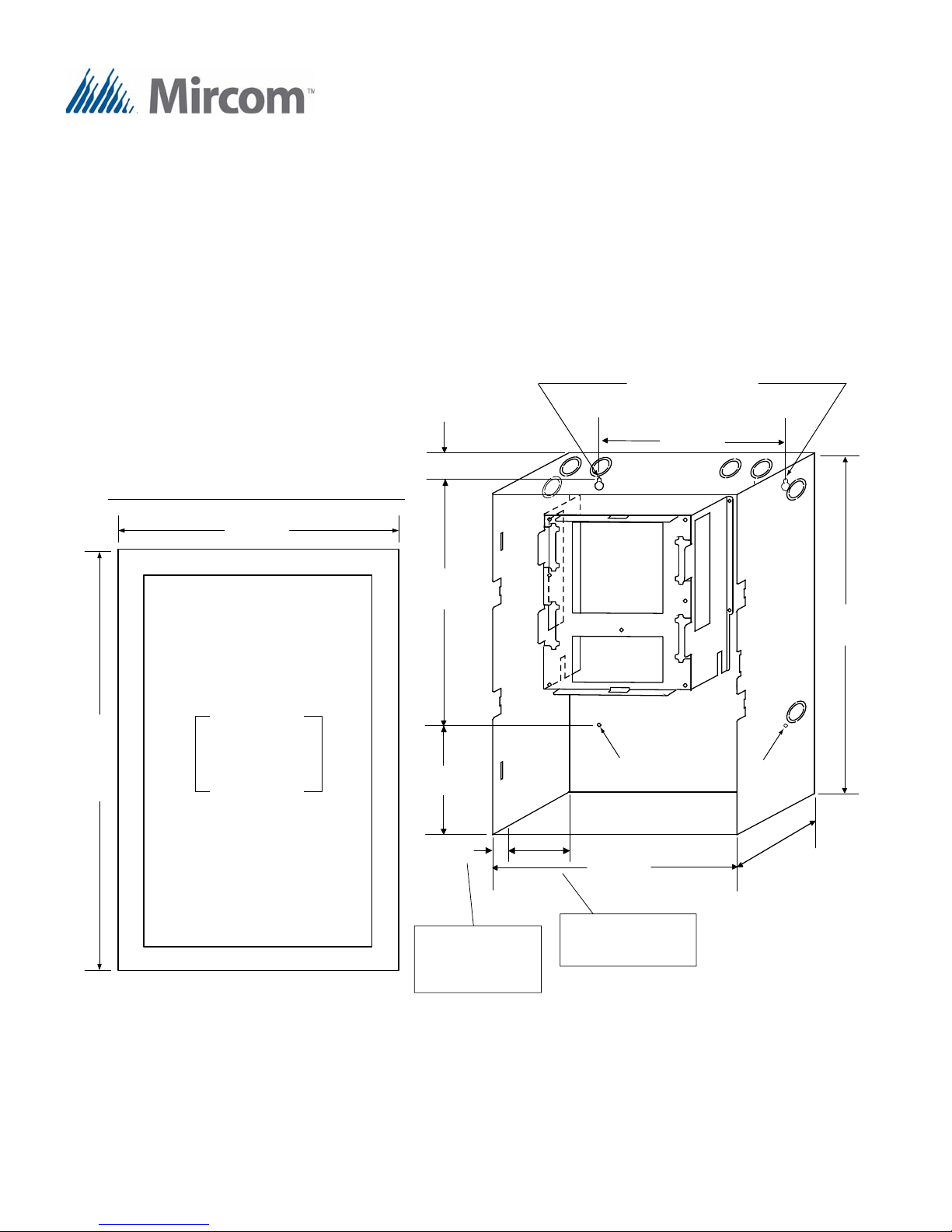
Adhere trim ring to
wall surface around
the FA-300 or FR-320
backbox.
PLACE FA-300-TRB TRIM RING OVER BACKBOX
14.5"
4
.
5
"
11"
20.0"
1.5"
4.0"
14.5"
3.5"
1"
3.5" is the maximum depth
for semi -fl ush mounting
using the flush trim ring
1" is the minimum depth
above the wal l r equired
for semi -fl ush mounti ng
using the flus h tri m ring
Mounting Holes for
Surface Mounting
Mounting Holes for
Surface Mounting
Addendum for New Chassis
Installation Instructions
Mechanical Installation for the FX-350, FA-300 and FR-320 Series Backboxes
and Chassis
All the FX-350, FA-300 Series Fire Alarm Panels including the FR-320 Series have a new chassis. See the following diagrams; Figure 1 for the small panel versions of all the series and Figure 2 for the larger panel version of the FX-350 and
FA-300 series.
Figure 1: Backbox and Trim Ring Dimensions for Models FA-300-3DR/-3DDR,
FA-300-6DDR, FX-350-60-DR and FR-320-R/-W, FR-320-DR/-DW
LT- 1087 Rev. 0 Nov 2010 Page 1 of 2
Page 2
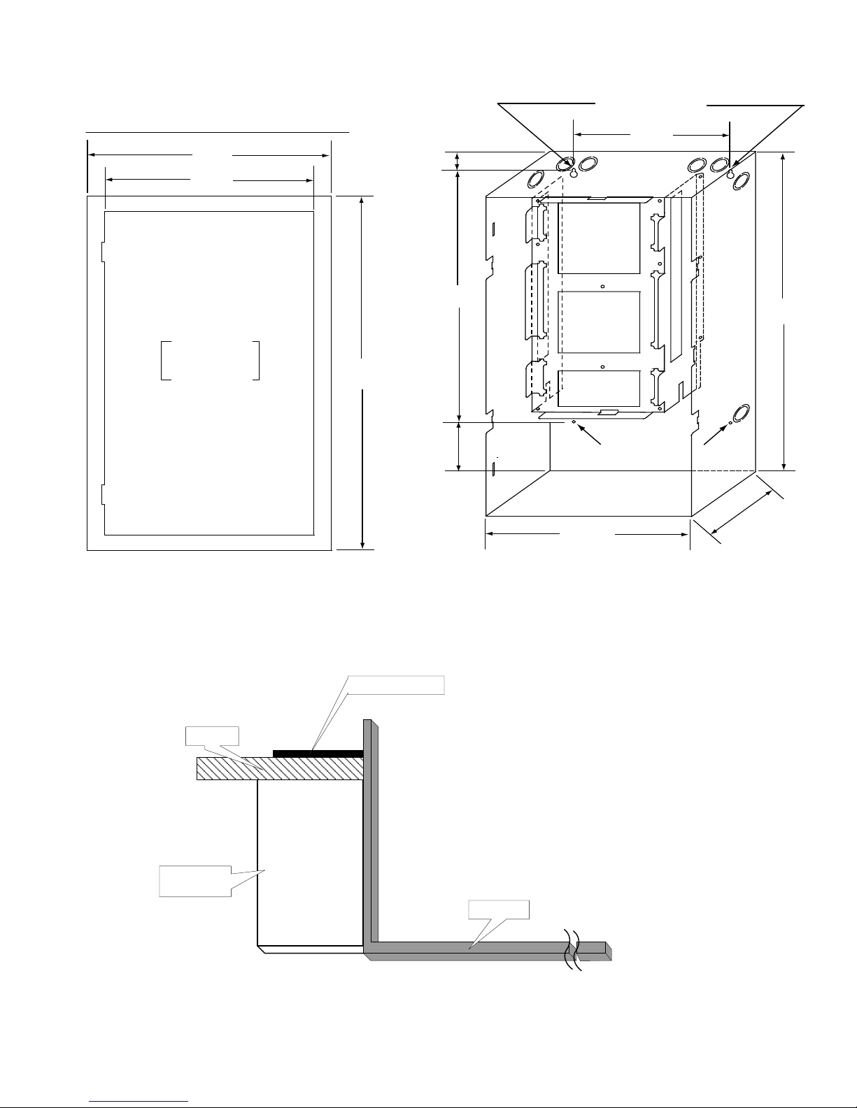
Figure 2: Backbox and Trim Ring Dimensions for Models FX-351-LW/-LDW/-LDR,
Mounting Holes
Mounting Holes
11”
20.5”
1.5”
14.5”
14.5”
26”
4”
4.5”
17”
28.5”
Adheretrim ring to
wall surface around
the FA- 300 backbox.
PLACE FA-UNIV-TRB TRI M RING OVER BACKBOX
TRIM RING
WALL
WOOD OR
METAL STUD
BACKBOX
FX-353-LW/-LDR, FA-301-8LR/-8LW/-8LDR/W and FA-301-12LR/-12LW,
FA-301-12LDR/-12LDW, FA-301-12 DDR
Mounting the Boards to the Chassis
The main board is mounted to the chassis and is shipped out this way. All adder modules are mounted in the same manner
as explained in the respective fire alarm manual.
Figure 3: Cross-Section of Flush Mounted Backbox
Wiring
All wiring is as explained in the respective fire alarm panel manual.
LT- 1087 Rev. 0 Nov 2010 Page 2 of 2
 Loading...