

Page 1
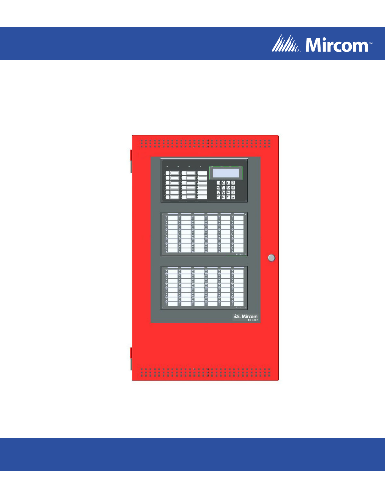
FX-3500RCU
Fire Alarm Control Panel
FM APPLICATIONS MUST HAVE CLASS A INITIATING CIRCUITS ONLY AND 90 HOUR BATTERY STANDBY OPERATION
Releasing Application Guide
LT-1091 Rev 2
Novenber 2015
Page 2

Page 3

Table of Contents
1.0 Operating the Panel 3
1.1 Hazard Zones ..................................... ... ... .......................................... ... .... .................... 3
1.2 Counting Zone Type ...................................................................................................... 3
1.3 Abort Type ..................................................................................................................... 3
1.4 Configurable Timers ....................................................................................................... 4
1.5 Hazard Zone States .. ... ... .... ... ... ... ... .... ... .......................................... ... ... .... ... ... .............. 4
1.5.1 Hazard Idle ...................... .... ... ... ... ... .... ... ... .......................................... ... .... .................... 4
1.5.2 Hazard Alarm (pre-discharge) ........................................................................................ 5
1.5.3 Hazard Release ............................................................................................................. 5
1.6 General Operation ......................................................................................................... 5
2.0 Releasing Circuit Wiring 6
2.1 Releasing Circuit Wiring - Class B/Style Y Wiring ......................................................... 6
3.0 Typical Releasing Applications 7
3.1 Pre-Action/Agent Release, Single Activation Application .............................................. 7
3.2 Pre-Action/Agent Release, Double Activation Application ............................................. 8
3.3 Pre-Action/Agent Release, Triple Activation Application ............................................... 9
3.4 Pre-Action/Agent Release, 2 Input Type Activation Application .................................... 10
3.5 Deluge, Single Activation Application ............................................................................ 11
3.6 Deluge, Double Activation Application ........................................................................... 12
3.7 Deluge, Triple Activation Application ..................................... ... .... ... ... ... .... ... ... ... ... .... ... . 13
3.8 Deluge, 2 Input Type Activation Application .................................................................. 14
4.0 Compatible Solenoids 15
1
Page 4

Table of Contents
2
Page 5

1.0 Operating the Panel
!
i
Attention: ONLY UL/ULC LISTED MANUAL ABORT AND MANUAL RELEASE
SWITCHES, SUCH AS THE MIRCOM SS-2004, ARE PERMITTED FOR
USE.
The TS1 terminal on the power supply board (MD-1011) is dedicated to supply power for
releasing devices. For wiring information see LT-1083RCU FX-3500RCU Installation Manual.
1.1 Hazard Zones
Hazard zones are configurable by correlating input devices, releasing circuits, (pre)release
signals, and manual release and abort switches.
Notes: Abort switches are only configurable in Preaction/Agent release applications.
Soak Delay timer is only configurable for Deluge applications.
Operating the Panel
1.2 Counting Zone Type
Releasing applications must be configured with one of the following Counting Zone types:
Single Activation of any one input device correlated to the hazard zone will initiate
the release process.
Double Activation of any two input devices correlated to the hazard zone will confirm
the alarm and initiate the release process.
Triple Activation of any three input devices correlated to the hazard zone will
initiate the release process.
2 Input Types Activation of any two different input device types (ion, photo, heat etc.)
correlated to the hazard zone will initiate the release process.
1.3 Abort Type
Releasing applications must be configured with one of the following Delay Timer types:
ULI Press Abort and the timer continues to count down and stops and holds at 10 seconds.
Release the ABORT switch and the timer resumes the countdown at 10 seconds.
IRI Same as ULI with the following condition: For the Abort switch to function, you must press
and hold the Abort switch before the second zone goes into alarm.
NYC Pressing the Abort switch causes the control panel to add 90 seconds to the Release
Delay Timer (RDT).
Pressing and holding the Abort switch stops the Release Delay Timer (RDT) from
counting down. Releasing the Abort switch resumes the count down of the RDT.
AHJ The timer does not start while you press and hold the Abort switch. Press the Abort switch
and the timer resumes counting down. Press the Abort switch again to restor e the timer to
its full value. Release the Abort switch and the timer resumes counting down.
3
Page 6

1.4 Configurable Timers
!
Releasing applications may be configured with the following timers:
Operating the Panel
Release Delay Timer
(RDT)
Soak Delay Timer
(SDT)
Manual Release Delay Timer
(MRDT)
Attention: Manual Release cannot be aborted once it has been initiated. Use ULC-
S528 listed Manual Release such as MS-704(U) and MS-714(U).
1.5 Hazard Zone States
The escalating Hazard Zone states are as follows:
The amount of time from when the Hazard Zone is activated
via correlated input devices until release.
The maximum value for the RDT is 60 seconds.
The amount of time that the releasing circuit will be active.
Upon the expiration of Soak Timer, the releasing circuits will
be shut off. Only configurable in Deluge applications.
The maximum value for the SDT is 600 seconds.
Configuring the SDT to 0 seconds causes the releasing
circuits to shut off ONLY when the system is reset.
The amount of time from when the Manual Release Switch is
pressed until release.
The maximum value for the MRDT is 60 seconds.
• Hazard Idle
• Hazard Alarm
Hazard Release.
•
e states are defined based on the st a tus of Hazard Area input devices, and correl ated Abort
Th
and Manual Release Switches.
1.5.1 Hazard Idle
The Hazard Zone is Idle when:
• Release Delay Timer (RDT) is not started.
• There are insufficient alarm conditions to activate the Hazard Zone. For more
information see Chapter 1.2 Counting Zone Type.
• Manual Release Switch is not active.
During this state:
• The corresponding NAC circuit(s) is off.
• Releasing circuit(s) is off.
4
Page 7

1.5.2 Hazard Alarm (pre-discharge)
!
!
The panel enters the Hazard Alarm state whe n:
• It detects the Hazard area confirming alarm input device. For more information on
confirming alarms see Chapter 1.2 Counting Zone Type.
OR
Operating the Panel
• For a Single Counting Zone hazard area, a single alarm input device will put the Haza
Z
one into the Hazard Alarm state.
OR
• Manual Release switch is activated.
The releasing process continues as follows:
• Release Delay Timer (RDT) or Manual Release Delay Timer (MRDT) is started.
• Corresponding NAC(s) turns on at Alert rate.
1.5.3 Hazard Release
The panel enters the Hazard Release state when:
• The Release Delay Timer (RDT) or Manual Release Delay Timer
releasing process continues as follows:
The
• The correlated releasing circuit is activated.
• Corresponding NAC(s) switch to Evac rate.
1.6 General Operation
• If the Hazard Zone is Idle, activation of a Manual Release Switch starts the Manual
R
elease Delay Timer (MRDT). The expiration of the MRDT activates the releasin
ci
• I
T
t
M
• If the Hazard Zone is activated by the Manual Release Switch, it cannot be aborted.
• If the Hazard Zone is acivated by any other method, any configur
ope
.
rcuits
f the Hazard Zone is active and the configured time for the Manual Release Dela
imer (MRDT) is less than the time remaining on the Rele ase Delay Timer (RDT), on
he MRDT expires the MRDT activates and release occurs. If the RDT is less than
RDT, once the RDT expires the RDT activates and release occurs.
rate as described in 1.3 Abort Type.
rd
(MRDT) expires.
g
y
ce
the
ed abort switches will
• System Reset will reset all circuits, including releasing circuits.
Attention: When using a system that requires the acitvation of two automatic
detection devices, detector installation spacing must be reduced to 0.7
times the linear spacing in accordance with National FIre Alarm Code,
NFPA 72.
Caution: To ensure a Manual Release Switch overrides an Abort Switch, in the FX-
3500RCU configuration software set the Man Rel Priority flag for the Hazard
Zone zone to Yes.
5
Page 8

2.0 Releasing Circuit Wiring
INPUT CIRCUIT WIRING: FM APPLICATIONS MUST HAVE CLASS A
INITIATING CIRCUITS ONLY AND 90 HOUR BATTERY STANDBY OPERATION
Only addressable M500S and MIX-M500SAP supervised output modules can be used as a
releasing circuit.
If the releasing circuit is wired as Class B, supervision of the solenoid coil is performed by the
MP-3500R/W Solenoid EOL.
Wiring for the releasing circuit is shown in Figure 1.
Solenoid EOL module (MP-3500R/W) is used to supervise the solenoid coil. If the solenoid is
already fitted with the directional diode then only the 47K EOL resistor is used. The
supervisory current passes through the solenoid coil thus confirming the integrity of the
solenoid coil for open coil. The wiring is supervised for the open and short conditions.
2.1 Releasing Circuit Wiring - Class B/Style Y Wiring
Operating the Panel
WARNING!
DISCONNECT POWER TO ALL RELEASING
DEVICES BEFORE SERVICING THE PANEL
MIX-M500MAP
MONITOR MODULE
0
9
8
7
6
9
5
4
8
1
3
2
1
7
0
2
TENS
8
7
6
9
5
6
3
4
3
2
5
4
1
0
ONES
ADDRESS
LOOP
SLC LOOP WIRE
(-)
(+)
EOLR
REDBLACK
EOLR-1A EOL
SUPERVSION
RELAY
VIOLET VIOLET
A LOOP1
+
B
+
POWER LINE 24 VDC
TWISTED PAIRS RECOMMENDED
SPECIAL APPLICATION PER UL864,
POWER LIMITED PER NFPA 70.
LISTED FOR FIRE PROTECTION
WITH BATTERY BACKUP.
TS1
+ -
(+)
(-)
SOLENOID COIL
MP-3500R/W
SOLENOID EOL MODULE
6
(-)
(+)
4
8
3
2
1
7
0
TENS
8
7
6
9
5
6
4
3
2
5
1
0
ONES
ADDRESS
LOOP
MIX-M500SAP
SUPERVISED
1
2
3
4
(-)
(+)
ALL WIRING SHOWN IS SUPERVISED AND POWER LIMITED
0
9
8
7
6
9
5
CONTROL MODULE
Figure 1 Releasing Circuit Wiring - Class B or Style Y Wiring
Page 9

3.0 Typical Releasing Applications
3.1 Pre-Action/Agent Release, Single Activation Application
Devices
SLC Loop
Any Detector in Hazard
Zone
Releasing Agent
Addressable Module
Abort Switch
Manual Release Switch
Logic
AND Gate
Both inputs are required.
Logic Path
OR Gate
If either input is activated
release occurs.
NOT Gate
Input is required to be not
activated.
7
Delay Timer
Use FX-3500RCU
Configurator to set type.
• a single detector correlated to the Hazard Zone enters alarm
Release commences if the following events occur:
Operating the Panel
• the abort switch is not pressed
• the delay timer expires
OR
• the Manual Release Switch is pressed
• the delay timer expires
Page 10

8
3.2 Pre-Action/Agent Release, Double Activation Application
Devices
SLC Loop
Any Detector in Hazard
Zone
Releasing Agent
Addressable Module
Abort Switch
Manual Release Switch
Logic
Logic Path
AND Gate
Both inputs are required.
NOT Gate
Input is required to be not
activated.
OR Gate
If either input is activated
release occurs.
Delay Timer
Use FX-3500RCU
Configurator to set type.
Release commences if the following events occur:
• two detectors correlated to the Hazard Zone enter alarm
• the abort switch is not pressed
• the delay timer expires
OR
• the Manual Release Switch is pressed
• the delay timer expires.
Operating the Panel
Page 11

3.3 Pre-Action/Agent Release, Triple Activation Application
Devices
Logic
SLC Loop
Any Detector in Hazard
Zone
Releasing Agent
Addressable Module
Abort Switch
Manual Release Switch
Logic Path
AND Gate
Both inputs are required.
NOT Gate
Input is required to be not
activated.
OR Gate
If either input is activated
release occurs.
Delay Timer
Use FX-3500RCU
Configurator to set type.
9
• three detectors correlated to the Hazard Zone enter alarm
Release commences if the following events occur:
• the abort switch is not pressed
• the delay timer expires
OR
• the Manual Release Switch is pressed
• the delay timer expires.
Operating the Panel
Page 12

10
3.4 Pre-Action/Agent Release, 2 Input Type Activation Application
Devices
SLC Loop
Smoke Detector
Heat Detector
Releasing Agent
Addressable Module
Abort Switch
Logic
Manual Release Switch
Logic Path
AND Gate
Both inputs are required.
NOT Gate
Input is required to be not
activated.
OR Gate
If either input is activated
release occurs.
Delay Timer
Use FX-3500RCU
Configurator to set type.
Release commences if the following events occur:
• two detectors of different types correlated to the Hazard Zone enter alarm
• the abort switch is not pressed
• the delay timer expires
OR
• the Manual Release Switch is pressed
• the delay timer expires.
Operating the Panel
Page 13

3.5 Deluge, Single Activation Application
Devices
Logic
SLC Loop
Any Detector in Hazard
Zone
Deluge System
Addressable Module
Manual Release Switch
Logic Path
OR Gate
If either input is activated
release occurs.
Delay Timer
Use FX-3500RCU
Configurator to set type.
Deluge commences if the following events occur:
11
• a single detector correlated to the Hazard Zone enters alarm
• the delay timer expires
OR
• the Manual Release Switch is pressed
• the delay timer expires.
Operating the Panel
Page 14

12
3.6 Deluge, Double Activation Application
Devices
SLC Loop
Any Detector in Hazard
Zone
Deluge System
Addressable Module
Manual Release Switch
Logic
Logic Path
AND Gate
Both inputs are required.
OR Gate
If either input is activated
release occurs.
Delay Timer
Use FX-3500RCU
Configurator to set type.
Deluge commences if the following events occur:
• two detectors correlated to the Hazard Zone enter alarm
• the delay timer expires
OR
• the Manual Release Switch is pressed
• the delay timer expires.
Operating the Panel
Page 15

3.7 Deluge, Triple Activation Application
Devices
Logic
SLC Loop
Any Detector in Hazard
Zone
Deluge System
Addressable Module
Manual Release Switch
Logic Path
AND Gate
Both inputs are required.
13
NOT Gate
Input is required to be not
activated.
OR Gate
If either input is activated
release occurs.
Delay Timer
Use FX-3500RCU
Configurator to set type.
Deluge commences if the following events occur:
• three detectors correlated to the Hazard Zone enter alarm
• the delay timer expires
OR
• the Manual Release Switch is pressed
• the delay timer expires.
Operating the Panel
Page 16

14
3.8 Deluge, 2 Input Type Activation Application
Devices
SLC Loop
Smoke Detector
Heat Detector
Deluge System
Addressable Module
Manual Release Switch
Logic
Logic Path
AND Gate
Both inputs are required.
NOT Gate
Input is required to be not
activated.
OR Gate
If either input is activated
release occurs.
Delay Timer
Use FX-3500RCU
Configurator to set type.
Deluge commences if the following events occur:
• two detectors of different types correlated to the Hazard Zone enter alarm
• the delay timer expires
OR
• the Manual Release Switch is pressed
• the delay timer expires.
Operating the Panel
Page 17

4.0 Compatible Solenoids
The following table lists the compatible solenoids.
Table 1 FX-3500RCU Compatible Solenoids
Manufacturer and Series Part Number Extended
Description
Parker 73212BN4TNLVNOC322C2 Valve Solenoid
Siemens 500-697913BG Valve Solenoid
8210G207 Valve Solenoid
ASCO
BSCO 510006 Actuator
TSP 17842 Actuator
Kidde-Fenwal 486500-01 Actuator
(FM Approved)
T8210A107 Valve Solenoid
Operating the Panel
TLX Technologies PA0036 Actuator
15
Page 18

Page 19

Page 20

CANADA - Main Office
25 Interchange Way
Vaughan, ON L4K 5W3
Tel: (888) 660-4655
(905) 660-4655
Fax: (905) 660-4113
U.S.A
4575 Witmer Industrial Estates
Niagara Falls, NY 14305
Tel: (888) 660-4655
(905) 660-4655
Fax: (905) 660-4113
TECHNICAL SUPPORT
North America
Tel: (888) Mircom5
(888) 647-2665
International
Tel: (905) 647-2665
© Mircom 2013
Printed in Canada
Subject to change without prior notice
www.mircom.com
 Loading...