

Mircom FX-2003-6DS, FX-2017S-12ADS, FX-2009-12DS, FX-2009S-12DS, FX-2003-12XTDS Installation And Operation Manual
...Page 1
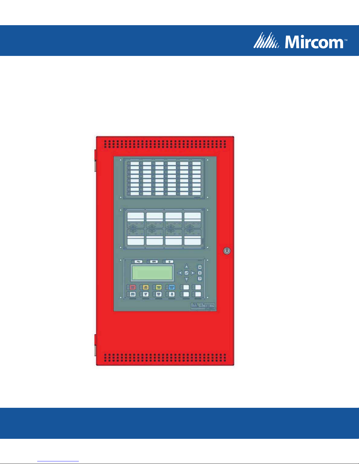
FX-2000
Intelligent Analog Fire Alarm Control Panel
Installation and Operation Manual
For the latest compatability information visit www.mircom.com/deviceguide
LT-657 Rev 15
December 2016
Page 2

Table of Contents
1.0 Introduction 1
2.0 Document Conventions 3
3.0 System Components 4
4.0 Mechanical and Chassis Installation 12
5.0 Module Mounting Locations 23
6.0 Display and Adder Modules Mounting Locations 25
6.1 FX-2003-6DS/FX-2003-12DS/FX-2003-6DS-16LED Compact Main Chassis ............... 25
6.2 FX-2017(S)-12DS Mid-size Main Chassis ...................................................................... 25
6.3 FX-2009(S)-12DS Large Main Chassis .......................................................................... 26
6.4 ECX-0012 Expander Chassis for FX-2009-12DS ........................................................... 26
7.0 Module Settings 29
7.1 Main Fire Alarm Modules (MD-764 Part of Main Chassis) ............................................. 29
7.2 Main Fire Alarm Super Module (MD-757 Part of “S” Version Main Chassis) ................. 30
7.3 RAX-1048TZDS Zone Display Module ........................................................................... 32
7.4 IPS-2424DS Programmable Input Switches Module ...................................................... 32
7.5 Fan Damper Control Display Module (FDX-008W/WKI) ................................................ 33
7.6 DM-1008A Hardwire Detection Adder Module ............................................................... 36
7.7 SGM-1004A Hardwire NAC Signal Adder Module ......................................................... 37
7.8 RM-1008A Hardwire Relay Adder Module ..................................................................... 39
7.9 Polarity Reversal and City Tie Module (Model PR-300) ................................................ 40
7.10 UDACT-300A Main Board .............................................................................................. 41
7.13 ALC-H16 Hardwire Loop Controller Module ................................................................... 47
8.0 Field Wiring 49
8.1 Main Fire Alarm Module Terminal Connections ............................................................. 49
8.2 Analog Loop Wiring ........................................................................................................ 51
8.3 NAC Signal Module (SGM-1004A) Terminal Connections ............................................. 58
8.6 UDACT-300A Main Board Terminal Connections .......................................................... 61
8.8 Wiring Tables and Information ........................................................................................ 63
9.0 System Checkout 65
i
Page 3

10.0 Indicators and Controls 66
11.0 Operation 72
11.1 Single Stage Operation .................................................................................................. 72
11.2 Two Stage Operation ..................................................................................................... 73
11.3 Pre-Signal Operation ...................................................................................................... 74
11.4 UUKL feature ................................................................................................................. 74
11.5 Output Circuit Delay Operation ...................................................................................... 74
11.6 Circuit Types .................................................................................................................. 75
12.0 Appendix A: Specifications 79
13.0 Appendix B: Compatible Devices 85
13.1 FX-2000 Series Compatible Addressable Loop Devices (UL) ....................................... 85
13.2 FX-2000 Series Compatible Two-Wire Smoke Detectors (UL) ...................................... 86
13.3 FX-2000 Series Compatible Four-Wire Smoke Detectors (UL Listed) ........................... 88
13.4 FX-2000 Series Compatible Signalling Devices (UL Listed) .......................................... 88
13.5 FX-2000 Series Compatible Addressable Loop Devices (ULC) ..................................... 89
13.6 FX-2000 Series Compatible Hardwire Smoke Detectors (ULC) .................................... 90
13.7 FX-2000 Series Compatible Synchronized Modules and Strobes ................................. 91
14.0 Appendix C: Power Supply and Battery Calculations 92
15.0 Appendix D: Remote Annunciator Panels 94
16.0 Appendix E: DIP Switch Settings Summary 96
17.0 Appendix F: Alarm Verification Timing 98
18.0 Appendix G: Wiring For Supervised Output Module 99
19.0 Appendix H: Label Requirements for Zone Identification 100
ii
Page 4

1.0 Introduction
1.1 About the FX-2000
Mircom's cost-effective FX-2000 Intelligent Analog Fire Alarm Control Panel (FACP) is a
flexible and easy-to-use analog system. The FX-2000 base panel consists of: one intelligent
analog loop controller capable of supporting 99 analog sensors and 99 addressable modules
that can be wired in Class A (Style 6 or 7) or Class B (Style 4). Analog sensors and
addressable modules consist of all compatibility listed devices including Advanced Protocol
devices. Loop adder modules are available for additional addressable (SLC) loops. The ALC198S provides one additional addressable loop, and the ALC-396S provides two addressable
loops each capable of supporting 99 analog sensors and 99 addressable modules. In addition,
the base panel supports up to 16 conventional adder modules such as the DM-1008A Initiating
Circuit Module, SGM-1004A NAC Circuit Module, and the RM-1008A Relay Circuit Module.
The base panel also includes 4 Class A/B (Style Z/Y) NAC circuits rated at 1.7 amperes each,
and either a 6- or 12-ampere power supply. The ALC-H16 adder board provides expansion for
16 additional conventional hardwire modules.
1.2 Overall Features
Introduction
• Large system capacity and modular design.
• Each Analog Loop is capable of supporting 99 analog sensors and 99 addressable
modules which can be wired as Class A (Style 6 or 7) or Class B (Style 4).
• The base system supports 16 conventional hardwire adder modules.
• 6 or 12 Ampere Power Supply.
• Four Class A/B (Style Z/Y) NAC Circuits rated at 1.7 Amperes each, which can be
configured as Audible or Visual (silenceable or non-silenceable circuits). Audibles may
be steady, Temporal Code, California Code, or March Time.
• NAC circuits may be configured to provide additional auxiliary power or resettable
auxiliary power.
• Fault isolators are present on all in panel addressable loops.
• Configurable Signal Silence Inhibit, Auto Signal Silence, Two-Stage Operation, One-
Man Walk Test.
• Outputs for 4 Wire resettable Smoke Power Supply, Auxiliary Power Supply, and an
interface to the Mircom RTI Remote Trouble Indicator.
• RS-485 Interface for Remote Multiplex Annunciators.
• Three Level Password Protection with field settable definition which enables the installer
to determine what functions are accessible for each of the three levels of pass
• Four queues for Alarm ACK, Supervisory ACK, Trouble ACK, and BLDG (Monitor) ACK,
with LED indicators and selector keys.
• Auxiliary Form-C Relay Contacts for Common Alarm, Common Supervisory, and
Common Trouble.
• RS-232 Port for remote system printer or “CRT terminal”.
• Two Event History Logs; one for Alarm related events and one for all events.
• Front Panel Auto-Configure and / or Personal Computer Configuration.
• Large 4 line by 20 character alphanumeric, back-lit LCD Display with user-friendly menu
system.
1
Page 5

Introduction
• Common controls and indicators for System Reset, Lamp Test, Fire Drill, Signal Silence,
General Alarm,
• General Alarm Cancel, AC On, Pre-Alarm, and Ground Fault.
• Two Spare configurable Keys and LED Indicators.
• 16 configurable LEDs (bi-coloured) with slide-in labels, available with the DSPL-420-
16TZDS display.
• Provides drift compensation for photoelectric smoke detectors.
• Provides Signal Coding of signal circuits for easy alarm identification (code consists of 1
to 4 digits, each digit consisting of 1-15 pulses on the signal).
• Selection for Canadian (ULC) or USA (ULI) requirements for Smoke Sensor sensitivity.
• Extensive transient protection.
• Surface Mountable Enclosures with removable doors for easy installation and service.
Flush Trims available.
• Removable Terminal Blocks for easy wiring and service.
• Loop Adder modules ALC-198S and ALC-396S for expanding addressable loops by 1
and 2 respectively.
• Adder module ALC-H16 hardwire loop interface board for expanding conventional input,
output, relay capability.
2
Page 6

2.0 Document Conventions
2.1 Circuits and Zones
The term circuits refers to an actual electrical interface, initiating (detection), NAC (signal), or
relay.
The term zone is a logical concept for a fire alarm protected area, and will consist of at least
one circuit.
Often the terms zone and circuit are used interchangeably, but in this manual the term circuit
is used.
On the FX-2000, circuits can be hardwired inputs and outputs or addressable inputs and
outputs. Both hardwired inputs and outputs, and addressable inputs and outputs may be
grouped together to form logical zones.
2.2 Wiring Styles
Document Conventions
Initiating circuits are configured by default as Class B (Style B). They may be globally (all or
none) configured as Class A (Style D) as described in the system configurator. This operation
uses odd and even pairs of two-wire Class B (Style B) circuits to make one four-wire Class A
(Style D) circuit, thus cutting in half the number of available initiating circuits.
Notification Appliance Circuits (NAC) circuits (also known as NAC circuits) may be
individually wired as Class A (Style Z) or Class B (Style Y) without affecting the number of
circuits available.
Addressable Loops may be configured system wide as Class B (Style 4) or Class A (Style 6).
With the addition of isolators, a Class A (Style 6) will become a Class A (Style 7).
3
Page 7
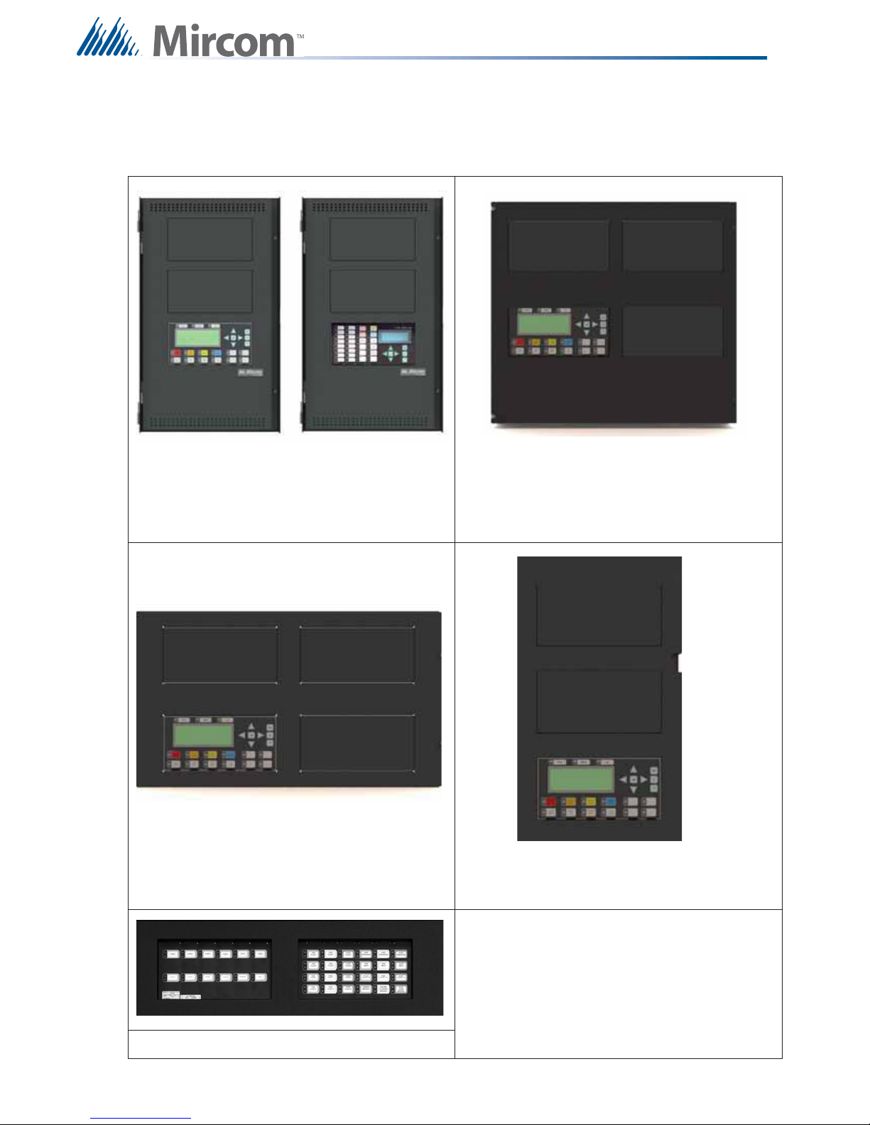
3.0 System Components
FX-2000 Chassis Types
System Components
FX-2003-6DS (pictured on the left) FX-2017-12ADS
FX-2003-6DS-16LED (pictured on the right) FX-2017S-12ADS
FX-2003-12DS (pictured on the left)
FX-2009-12DS FX-2003-12XTDS
FX-2009S-12DS
ECX-0012 Expander Chassis
4
Page 8
System Components
All FX-2000 Series Panels have the following features:
• Main Chassis with one analog loop
• 4 Style Y or Z NAC Circuits
• 4 line by 20 character back-lit LCD display
Table 1 details the specifics of each chassis type. Some models may not be available in all
markets. Verify with your local distributor.
Table 1 FX-2000 Chassis Types
Model Amps
# of
Addressable
loops
# of
NACs
# of
Adder
Modules
# of
Conventional
Adder
Max # of
Display
Adders
Mounts into
Modules
FX-2003-6DS 6 1 4 3 3 2 UB-1024DS
FX-2003-6DS-
16LED
FX-2003-12DS 12 1 4 3 3 2 UB-1024DS
FX-2003-12XTDS 12 1 4 9 9 2
FX-2009-12DS 12 1 4 9 16 3
FX-2009S-12DS 12 0 4 9 16 3
FX-2017-12ADS 12 1 4 17 16 3
FX-2017S-12ADS 12 0 4 17 16 3
6 1 4 3 3 2 UB-1024DS
BBX-1024XT
or
BBX1024XTR
BB-5008 or
BB-5014
BB-5008 or
BB-5014
BBX-1072ADS
or BBX1072ARDS
BBX-1072ADS
or BBX1072ARDS
EXC-0012 12 0 0 12 0 2
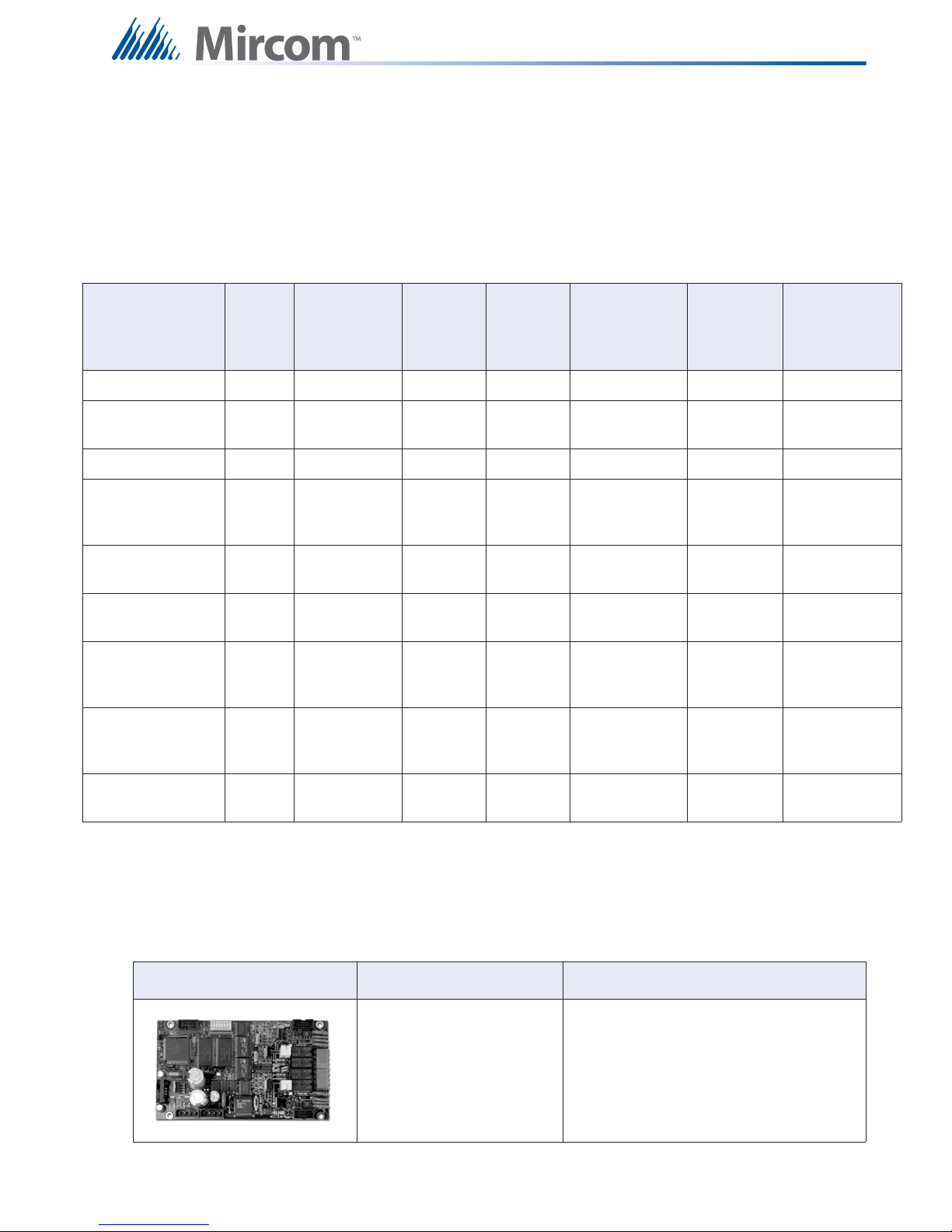
3.1 Adder Modules
The following table describes the adder modules used with the FX-2000.
Table 2 FX-2000 Adder Modules
Models Description
ALC-198S
Single Intelligent Analog Loop Controller
Module
BB-5008 or
BB-5014
5
Page 9

Table 2 FX-2000 Adder Modules
Models Description
System Components
ALC-396S
DM-1008A, SGM-1004A,
RM-1008A
DSPL-420-16TZDS
3.2 Auxiliary Modules
The following table describes the auxiliary modules used with the FX-2000.
Dual Intelligent Analog Loop Controller
Module
Conventional Circuit Adder Modules,
Detection, Signal and Relay.
Optional main display with 16
configurable bi-coloured LEDs.
This display is included in the
FX-2003-6DS-16LED chassis package.
Table 3 FX-2000 Auxiliary Modules
Model Description
PR-300 Polarity Reversal and City Tie Module
UDACT-300A Digital Communicator/Dialer Module
IPS-2424DS Programmable Input Switches Module
6
Page 10
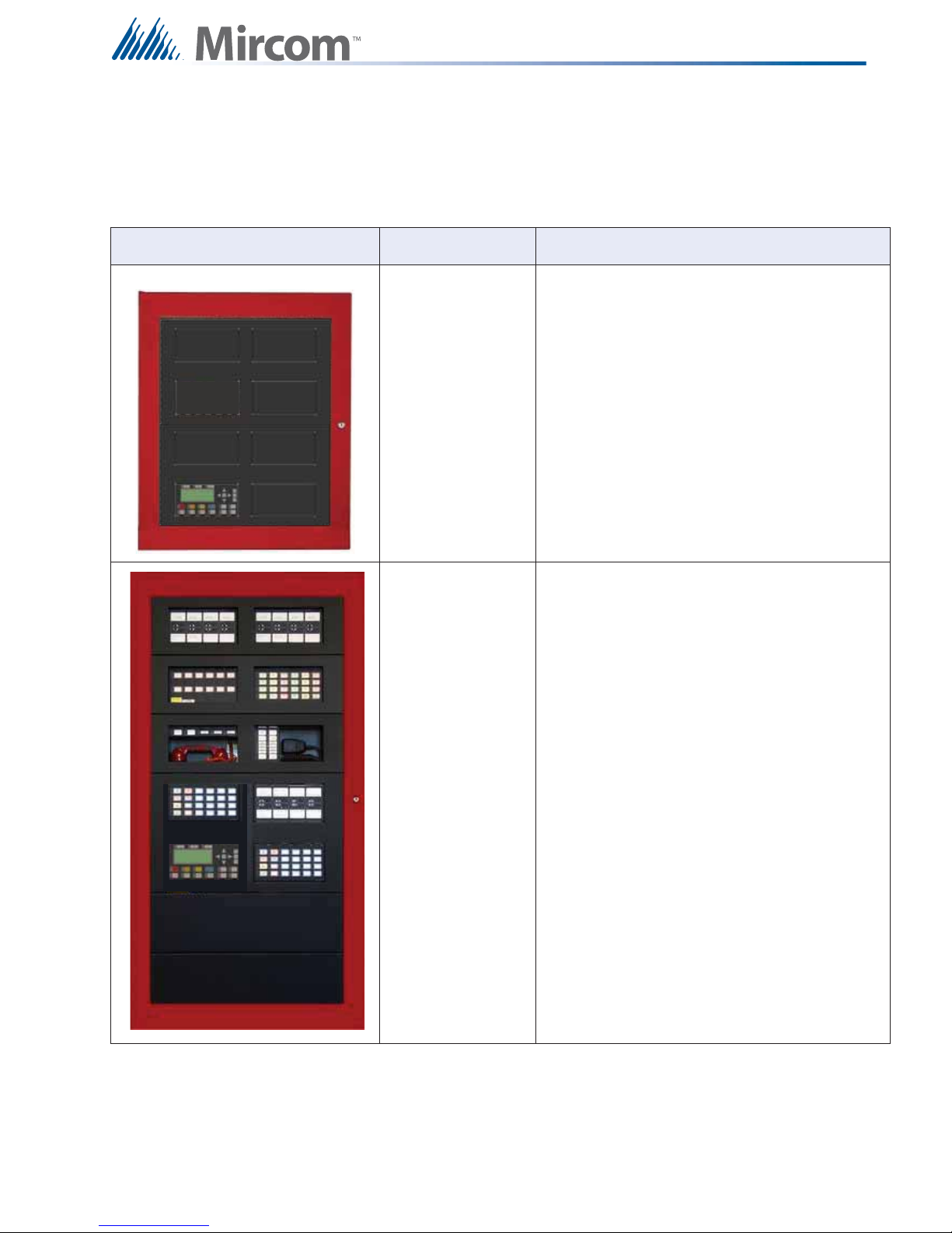
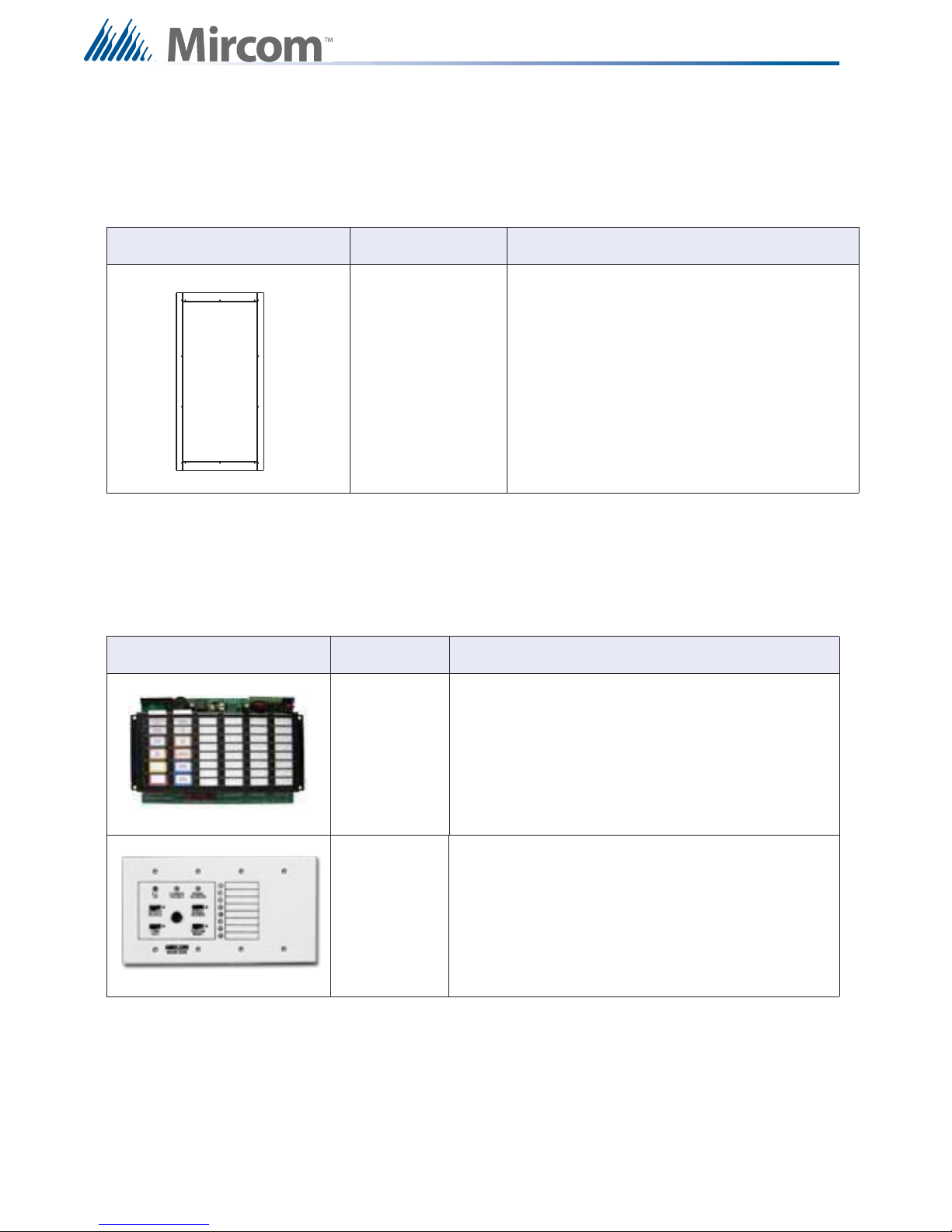
3.3 Enclosures
The following table describes the enclosures used with the FX-2000.
Table 4 FX-2000 Encl o su res
System Components
Model Description
BB-5008 Backbox 36”H x 30”W x 7”D
BB-5014 Backbox 60”H x 30”W x 7”D
7
Page 11

Table 4 FX-2000 Enclosures
Model Description
System Components
UB-1024DS
DOX-1024DS
DOX-1024DSR
FX-2003-6DS16LED
UB-1024DS Universal Backbox
26”H x 14.5”w x 4.2”D
DOX-1024DS white door for universal backbox.
DOX-1024DSR red door or universal backbox.
Complete system with DSPL-420-16TZDS
display and UB-1024DS backbox and
DOX-1024DSR door.
8
Page 12
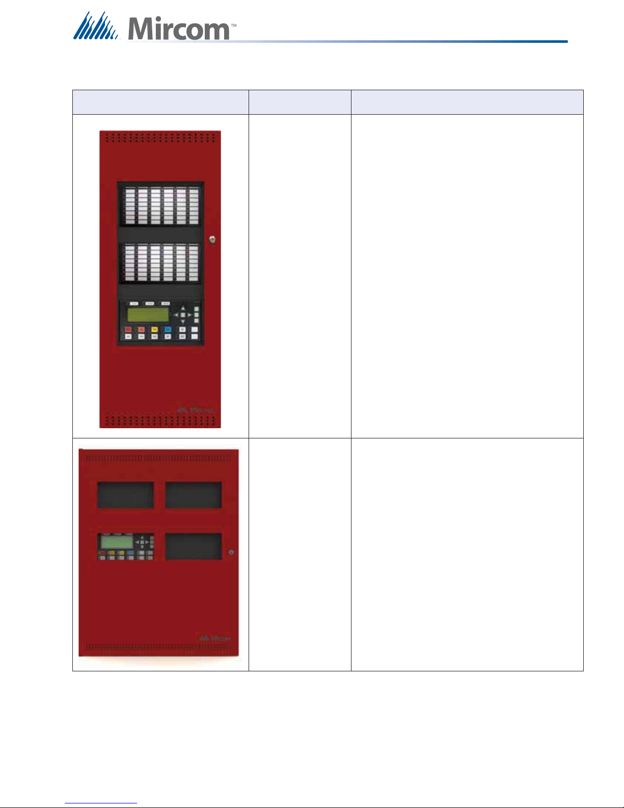
Table 4 FX-2000 Encl o su res
Model Description
System Components
BBX-1024XT
BBX-1024XTR
BBX-1072ADS
Enclosure 35.5”H x 14.5”w x 5.25”D, white door
Enclosure 35.5”H x 14.5”w x 5.25”D, red door
Enclosure 24.8” x 32.5” x 6.4”, white door
BBX-1072ARDS
Enclosure 24.8” x 32.5” x 6.4”, red door
9
Page 13
3.4 Flush Trim Ring
The following table describes the flush trim ring used with the FX-2000.
Table 5 FX-2000 Flush Trim Ring
System Components
Model Description
FA-XT-TRB
3.5 Remote Annunciators
The following table describes the remote annunciators used with the FX-2000.
Table 6 FX-2000 Remote Annunciators
Model
RA-1000
Series
Black flush trim ring for BBX-1024XT and
BBX-1024XTR.
Description
Remote multiplex annunciator panels. For Canada,
ULC-S527 Standard requires a Common Alarm,
Common Supervisory, and a Common Ground Fault
LED indicator on the Remote Annunciators. To meet
this requirement, use the FX-2000 Configurator to
correlate one LED for Common Alarm, one LED for
Common Supervisory and one LED for Common
Ground Fault.
10
RAM-208/216
Remote multiplex annunciator panels. For Canada,
ULC-S527 Standard requires a Common Alarm,
Common Supervisory, and a Common Ground Fault
LED indicator on the Remote Annunciators. To meet
this requirement, use the FX-2000 Configurator to
correlate one LED for Common Alarm, one LED for
Common Supervisory and one LED for Common
Ground Fault.
Page 14
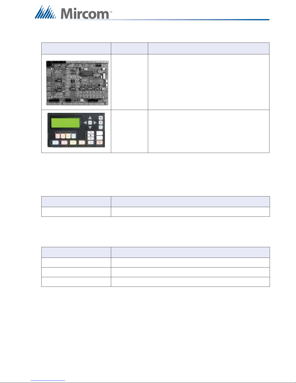
Table 6 FX-2000 Remote Annunciators
System Components
3.6 Batteries
The following table describes the batteries used with the FX-2000.
Model
MGD-32,
AGD-048
RAX-LCD Remote Shared Display Annunciator
Description
Remote graphic annunciator drivers. The AGD-048
must be installed in the same enclosure as the
MGD-032.
Table 7 Batteries
Model Description
Batteries 10 to 55 AH
3.7 FX-2000 Accessories
Table 8 Accessorie s
Model Description
MP-300/R/S End-of-line Resistor Plate, Beige, R for red, S for stainless steel finish
RTI-1 Remote Trouble Indicator (ULC and ULI listed)
BC-160 External Battery Cabinet (ULC and ULI listed)
11
Page 15

Mechanical and Chassis Installation
4.0 Mechanical and Chassis Installation
The following chapter describes the Mechanical and Chassis installation for all FX-2000
FAC Ps.
4.1 Mechanical Installation Diagrams
Mechanical Installation Instructions for the following enclosures:
• BB-5008
• BB-5014
• UB-1024DS and DOX-1024DS/R
• BBX-1024XT
• BBX-1024XTR
• BBX-1072ADS
• BBX-1072ARDS
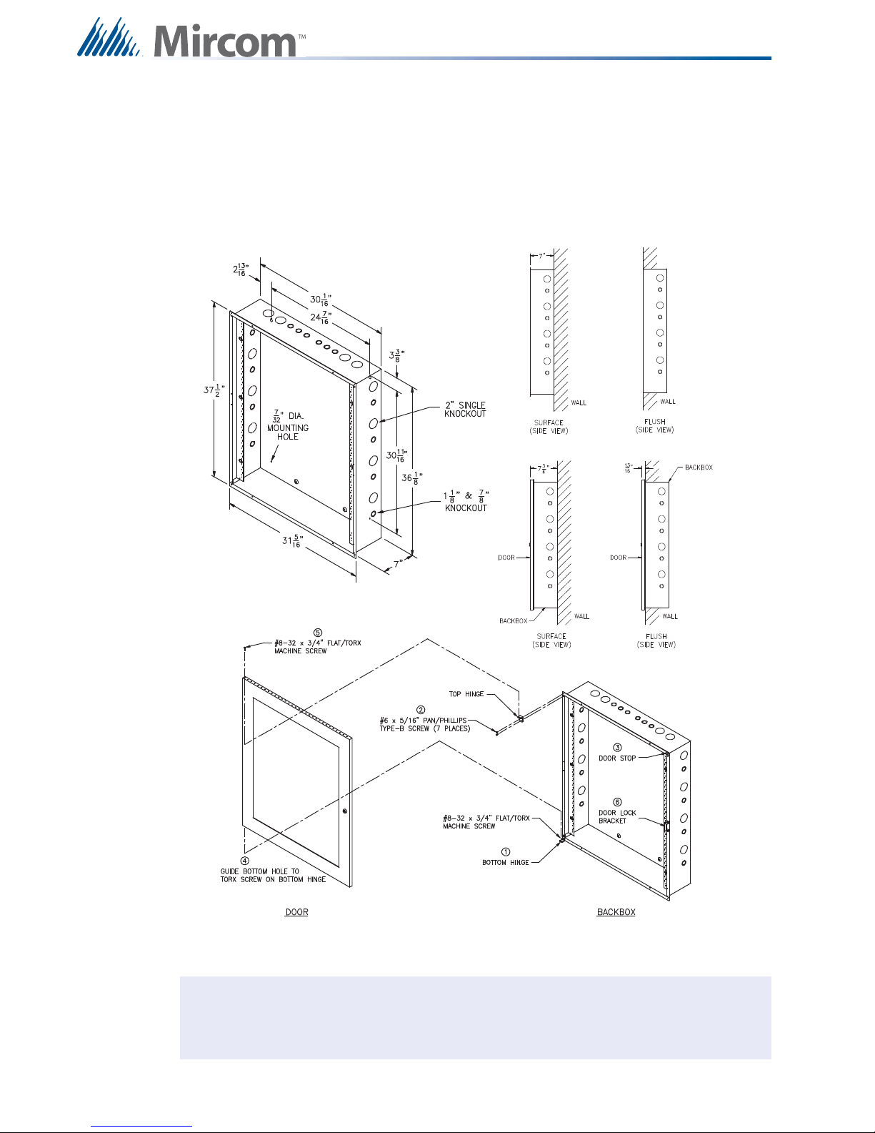
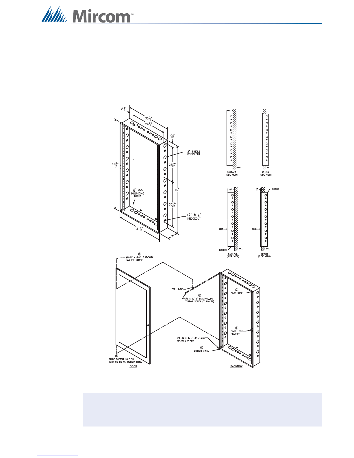
4.1.1 BBX-1072ADS and BBX-1072ARDS Mechanical Installation
Material Cold rolled steel18GA (0.048”) thick cold rolled steel
16GA (0.059”) thick for backbox
14GA (0.075”) thick for door
The BBX-1072ADS and BBX-1072ARDS are suitable for flush or surface mounting, and have
a built-in trim ring.
Dimensions of Enclosure (minus built in trim ring) 24.8” x 6.4” x 32.5”
Distance between horizontal mounting screws 16”
Distance between vertical mounting screws 23.6”
Complete Dimensions of Enclosures 26.4” x 7.7” x 34”
12
Page 16

Mechanical and Chassis Installation
i
Figure 1 BBX-1072ADS and BBX-1072ARDS Flush or Surface Enclosure Installation
and Dimensions
Note: Leave bottom of box conduit free for batteries.
13
Page 17
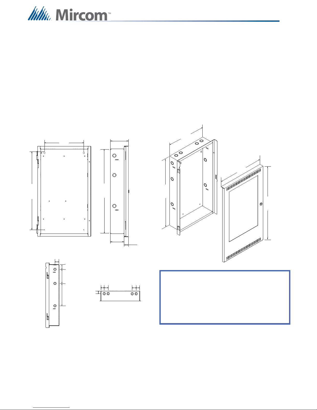
4.1.2 BB-5008 Mechanical Installation
Backbox
BB-5008 Backbox
DOX-5008M Metal Door
Backbox with DOX-5008M Door
i
Material Cold rolled steel18GA (0.048”) thick cold rolled steel
16GA (0.059”) thick for backbox
14GA (0.075”) thick for door
Mechanical and Chassis Installation
Figure 2 BB-5008 Enclosure Installation Instructions and Dimensions
Note: Leave bottom of box conduit free for batteries.
14
Page 18
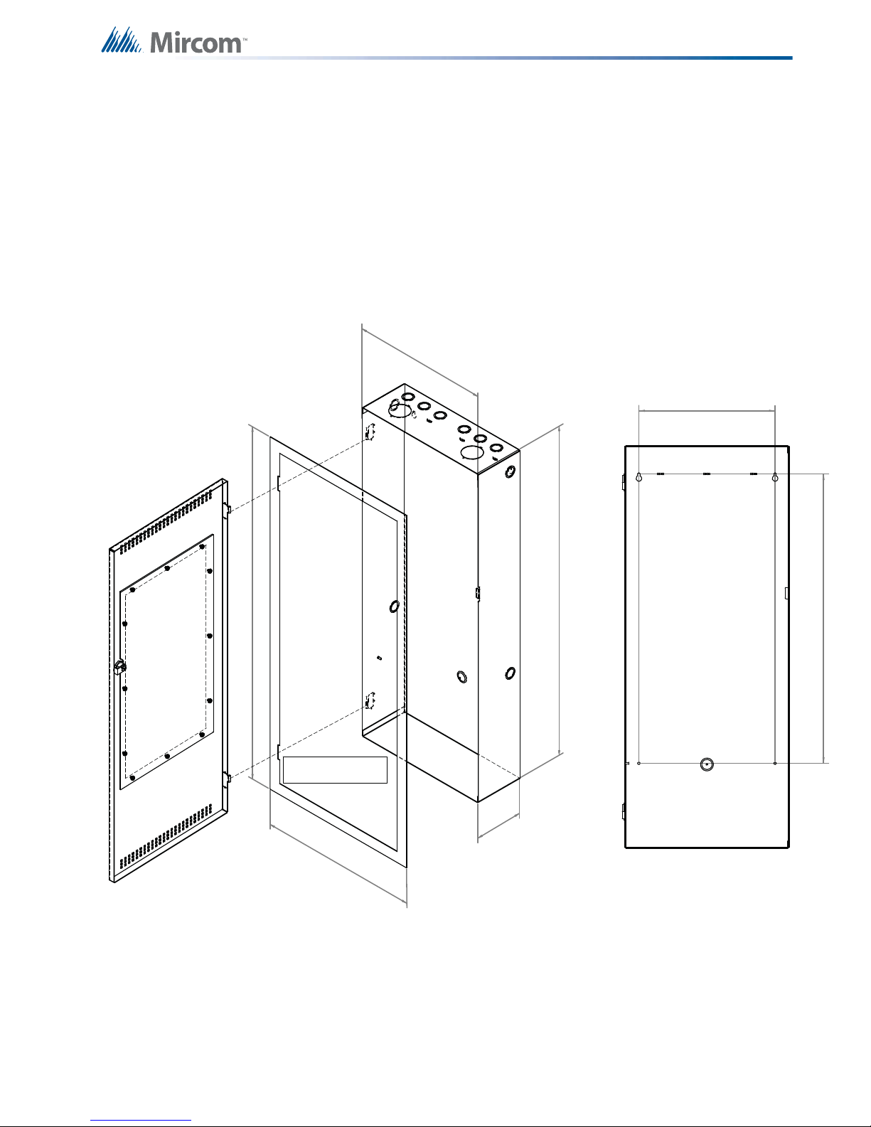
4.1.3 BB-5014 Mechanical Installation
Backbox
BB-5014 Backbox
DOX-5014M Metal Door
Backbox with DOX-5014M Door
i
Material Cold rolled steel18GA (0.048”) thick cold rolled steel
16GA (0.059”) thick for backbox
14GA (0.075”) thick for door
Finish Painted except for hinges
Mechanical and Chassis Installation
Figure 3 BB-5014 Installation Instructions and Dimensions
Note: Leave bottom of box conduit free for batteries.
15
Page 19
Mechanical and Chassis Installation
26 ”
17”
23 1/2”
14 1/2”
5 5/8”
1 3/8”
4 1/4”
12”
28 ”
26 ”
1 3/4”
1 3/4”
6”
2”
9 1/2”
1 3/4”
1 3/4”
2”
2”
TOP VIEW
SIDE VIEW
SIDE VIEW
BACKBOX
DOOR
BACKBOX FRONT VIEW
UB-1024DS UNIVERSAL BACKBOX AND DOX-1024DS/R DOOR
KNOCKOUT LOCATIONS
Dimensions of backbox (minus built-in trim ring)
Horizontal distance between mounting screws
Vertical distance between mounting screws
Complete dimensions of enclosure with door
Size of Knockouts
26”H x 14 1/2”W x 4 1/4” D
12”
1”
23 1/2”
28”H x 17”W x 5 5/8”D
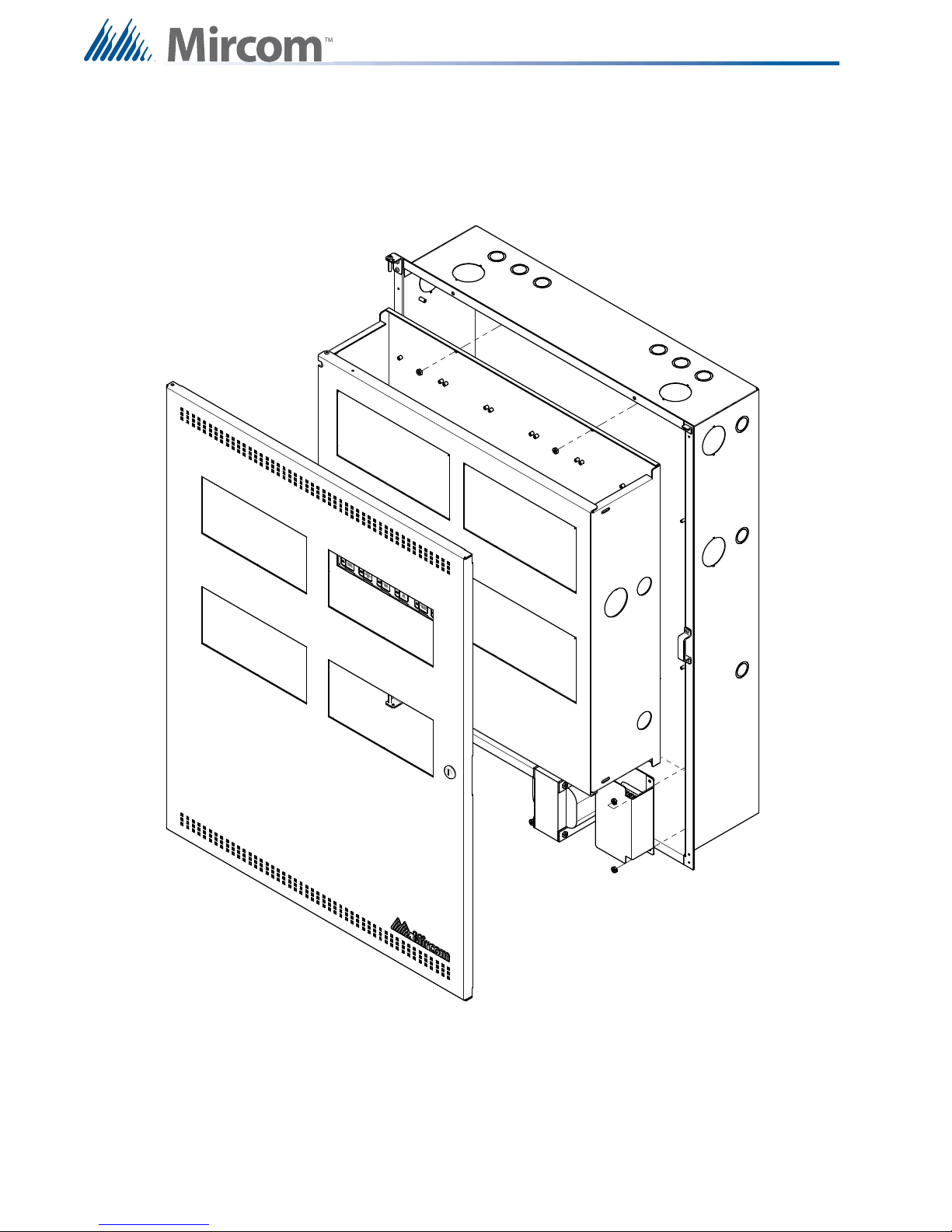
4.1.4 UB-1024DS and DOX-1024DS/R Mechanical Installation
The universal enclosure is suitable for flush or surface mounting, and have a built-in trim ring.
Dimensions of backbox (minus built in trim ring) 26” x 14.5” x 4.25”
Distance between horizontal mounting screws 12”
Distance between vertical mounting screws 23.5”
Complete Dimensions of Enclosure with door 28” x 17” x 5.6”
Figure 4 UB-1024DS and DOX-1024DS/R Installation Instructions and Dimensions
16
Page 20
4.1.5 FX-2003-12XTDS Mechanical Installation
14.500
35.500
5.25
17.000
38.010
12.000
25.500
Front Door
(Inside View)
FA-XT-TRB
Trim Ring for
Flush Mounting
Backbox
Adhere trim ring to wall
surface around backbox.
Backbox
Mounting Holes
FX-2003-12XTDS is an expanded version of the FX-2003-12DS.
Dimensions 14.76” wide by 35.8” long by 5.45”
16GA (0.059”) thick for backbox
14GA (0.075”) thick for door
Finish Painted except for hinges
Mechanical and Chassis Installation
Figure 5 BBX-1024XT/R Backbox Enclosure with Trim Ring
17
Page 21
Mechanical and Chassis Installation
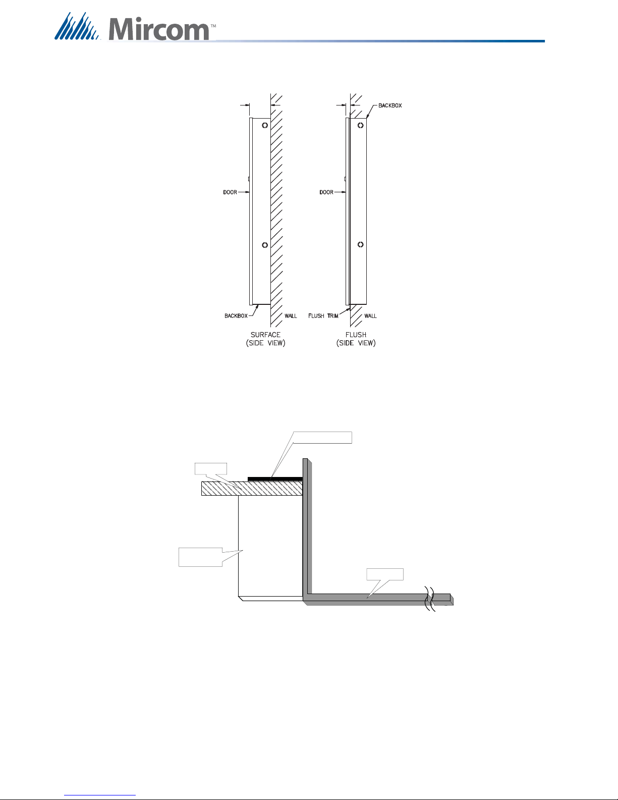
TRIM R ING
WALL
WOOD OR
METAL STUD
BACKBOX
4.1.6 Surface and Flush Mounting Views of the BBX-1024XT/R
5.45” 0.7”
Figure 6 BBX-1024XT/R Surface and Flush Side Views
4.1.7 BBX-1024XT Flush Mounted Box with FA-XT-TRB Trim Ring
Figure 7 Cross section view of mounted BBX-1024XT/R enclosure
18
Page 22

4.2 Chassis Installation
Chassis Installation Instructions for the following:
• FX-2003-6DS
• FX-2003-12DS
• FX-2003-12XTDS
• FX-2009-12DS
• FX-2009S-12DS
• FX-2017-12ADS
• FX-2017S-12ADS
• ECX-0012
For proper chassis installation do the following
1. Group the incoming wires through the top of the enclosure to prepare it for wiring the
modules. Do not run the wires in-between the modules since it could cause a short
circuit.
Mechanical and Chassis Installation
2. Use a wire tie to group wires for easy identification and neatness.
3. Be sure to connect a solid earth ground (from building system ground / to a cold water
pipe) to the chassis earth ground mounting lug, and to connect the earth ground wire
lugs from the main chassis to the ground screw on the backbox.
4. Mount chassis using the supplied hex nuts.
19
Page 23
Mechanical and Chassis Installation
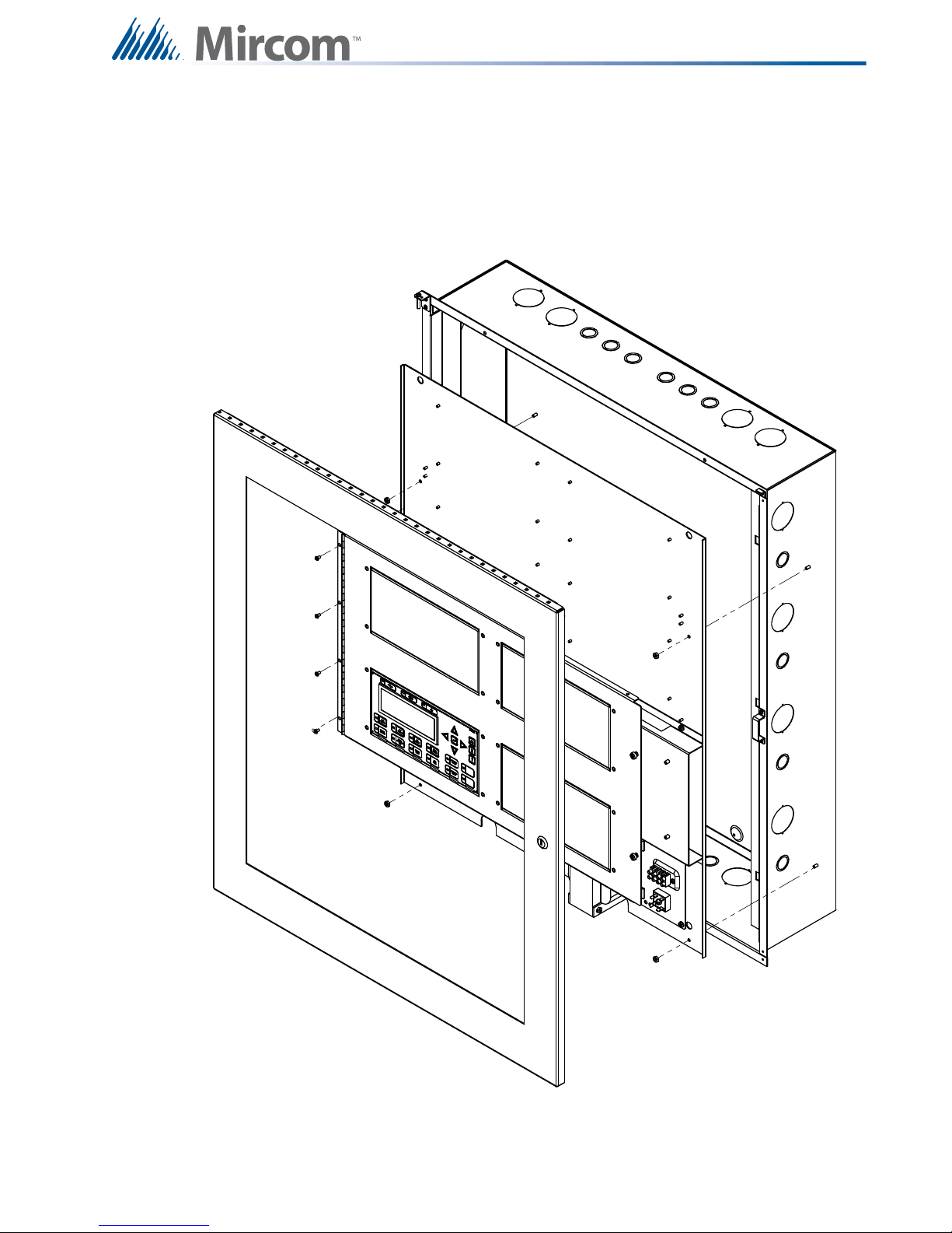
4.2.1 Mounting the Chassis into the BBX-1072ADS or BBX-1072ARDS
Enclosure
Mount chassis FX-2017-12ADS or FX-2017S-12ADS into backbox BBX-1072ADS or BBX1072ARDS using the supplied four #6 hex nuts (two at the top and two at the bottom) as
shown below. The transformer chassis is also mounted using four hex nuts.
Figure 8 Chassis Installation into BBX-1072ADS or BBX-1072ARDS Module Mounting
Locations
20
8 #8 hex nuts, 4 for inner
chassis and 4 for the
transformer chassis.
Page 24
Mechanical and Chassis Installation
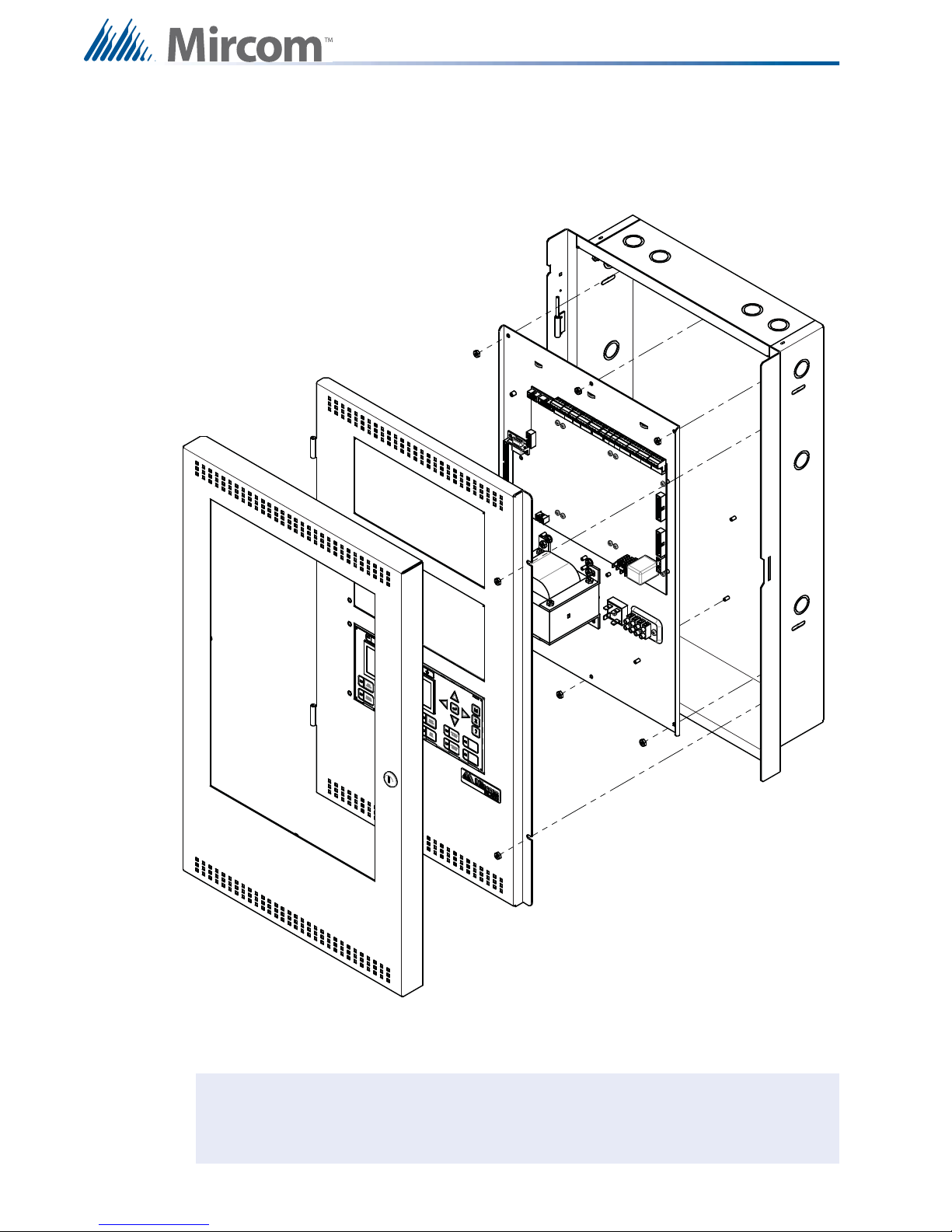
4.2.2 Mounting the Chassis into the BB-5008 or BB-5014
The chassis is mounted using the four #6 hex nuts provided. Two across the top portion and
two across the bottom of the chassis. The inner door is mounted using four hex nuts on the left
side and secured with two screws on the right side.
Figure 9 Chassis Installation into backbox BB-5008 and BB-5014
21
Page 25
Mechanical and Chassis Installation
i
4.2.3 Mounting the Chassis into the UB-1024DS and DOX-1024DS/R Enclosure
The chassis is mounted using the six #8 hex nuts provided. Three across the top and three
across the bottom of the chassis. The inner door mounts over the chassis with two #8 hex
nuts.
Figure 10
Note: Leave bottom of box conduit free for batteries.
22
Chassis Installation into Universal Enclosure UB-1024DS and DOX-1024DS/R
Page 26
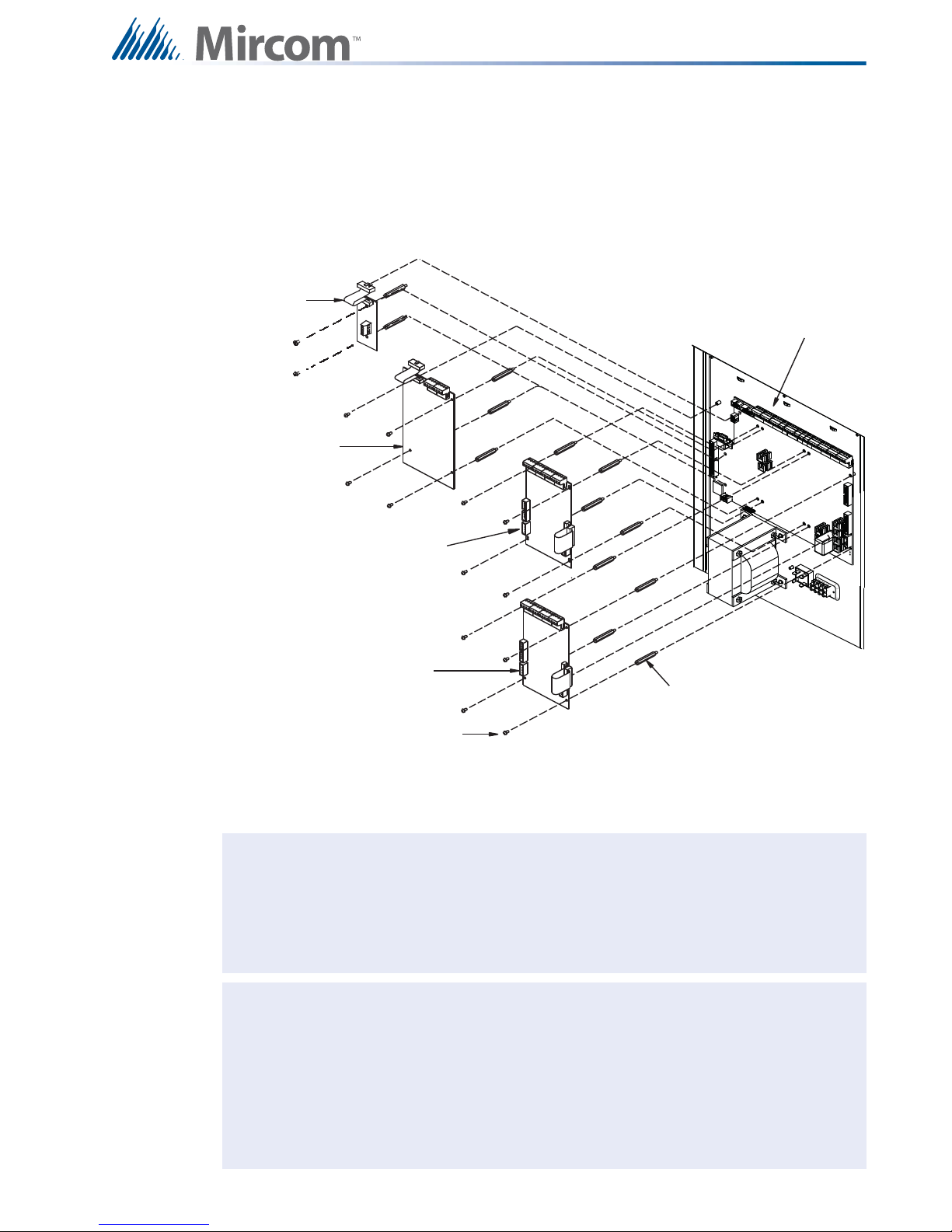
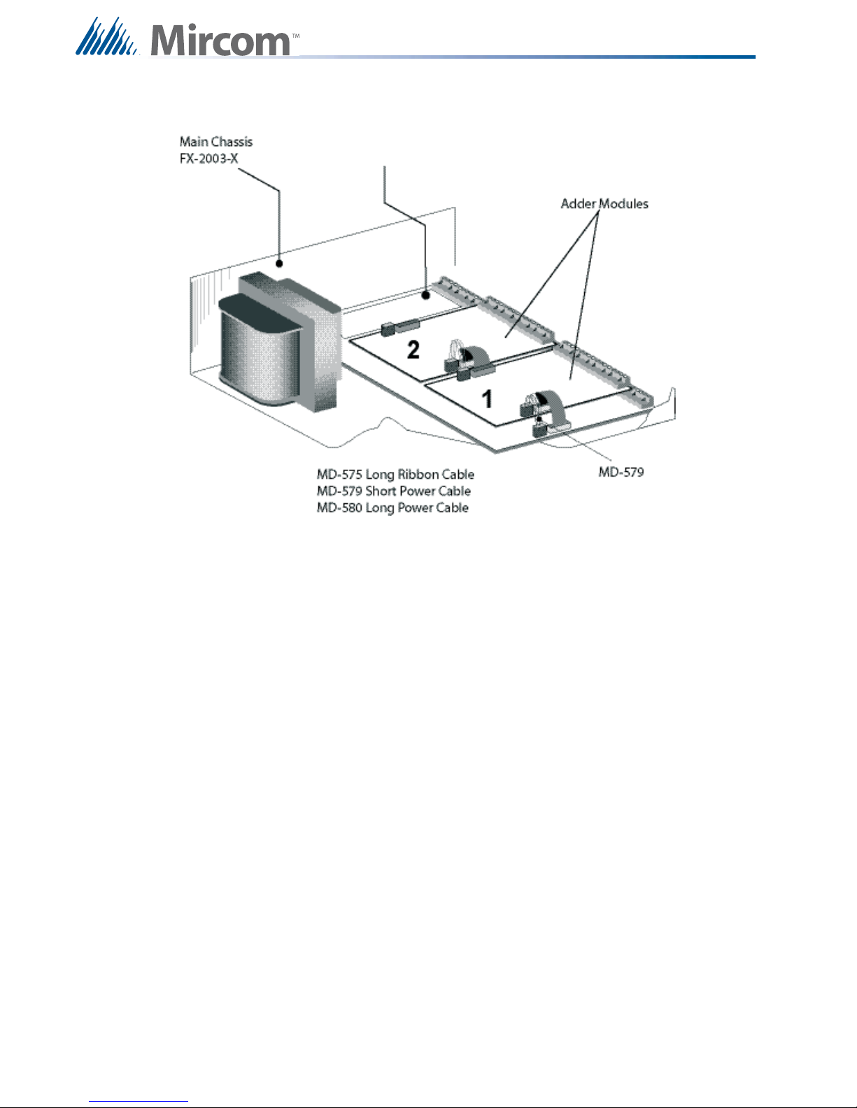
5.0 Module Mounting Locations
SCREWS
PROVIDED
M/F HEX SPACER
UDACT-300A
DIALER MODULE
OTHER ADDER
CIRCUIT MODULE
FX-2000
MAIN CHASSIS
OTHER ADDER
CIRCUIT MODULE
PR-300 CITY TIE MODULE
i
i
The FX-2003-6DS/12DS or FX-2017-12ADS Main Chassis come pre-assembled with a main
chassis, display components and boards. Install adder modules of different types as shown in
the diagrams on the following pages.
Module Mounting Locations
Figure 11 Module Mounting Loc ations View #1
Note: To enable communication from the main module to all of the adder modules, it is
necessary to add a continuity jumper on the last adder module in a chain (see the
appropriate module settings section to verify the location of the continuity jumper
Notes: Front plate is not shown. Reserved for PR-300 or UDACT-300A. Other circuit
on a particular circuit adder module). Only the last circuit adder module should
have a jumper plug on its continuity jumper; all others must be left without a
jumper plug.
adder modules may be:
• DM-1008A Detection Circuit Adder Module
• SGM-1004A Signal Circuit Adder Module
• RM-1008A Relay Circuit Adder Module
• ALC-198S Loop Adder Module
• ALC-396S Loop Adder Module
• ALC-H16 Hardwire Loop Controller Module
23
Page 27
Provision for PR-300 or UDACT-300A
Module Mounting Locations
Figure 12 Module Mounting Locations View #2
24
Page 28
Display and Adder Modules Mounting Locations
FX-2000 Main Board
123
Slot is reserved for
PR-300 or UDACT300A. If not
required, this slot
can be used to
mount any of the
adder modules.
1
23
45
67
89101112
1314151617
FX-2000 Main Board
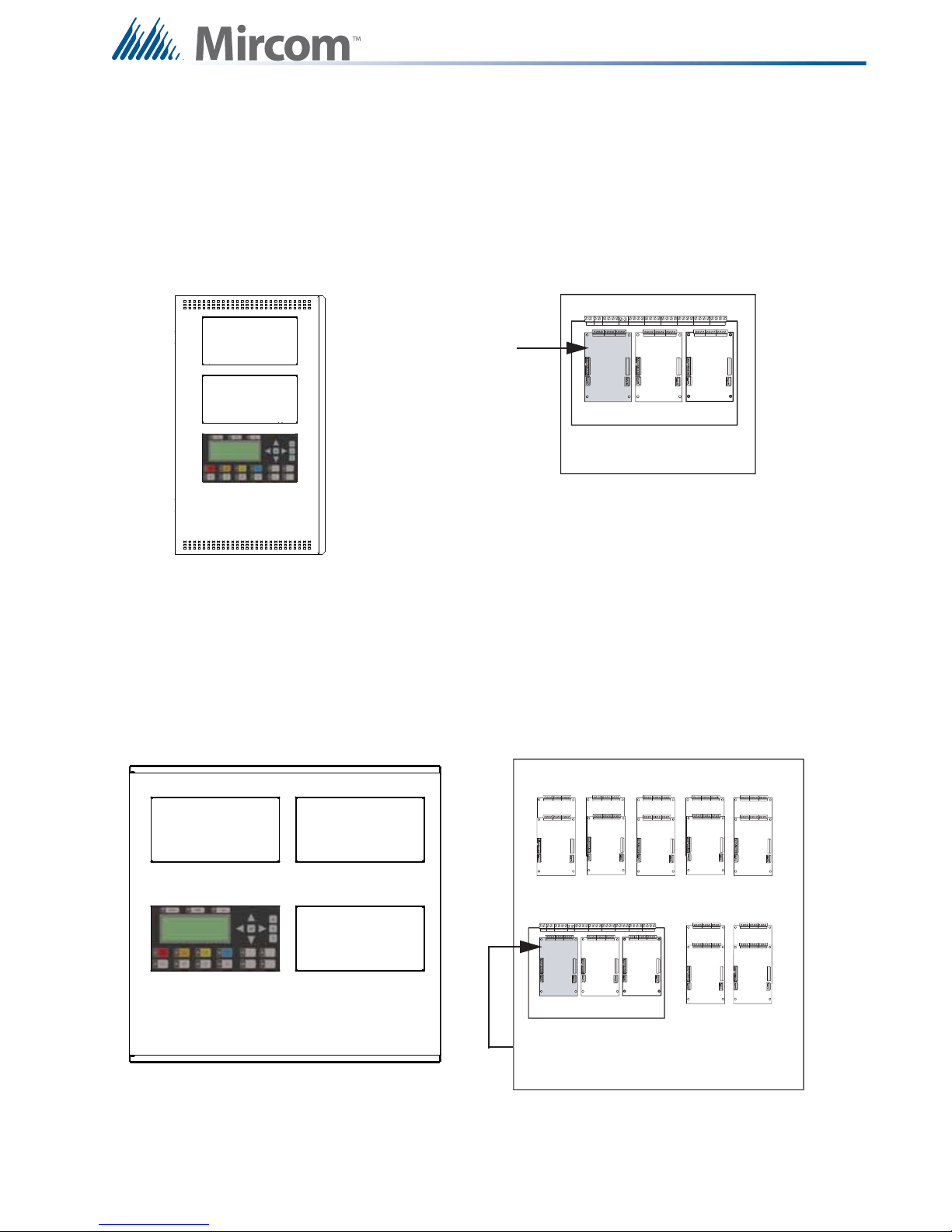
6.0 Display and Adder Modules Mounting Locations
6.1 FX-2003-6DS/FX-2003-12DS/FX-2003-6DS-16LED Compact
Main Chassis
Mounts in the UB-1024DS backbox and supports three circuit adder modules.
Exterior View Interior View
6.2 FX-2017(S)-12DS Mid-size Main Chassis
Mounts in the BBX-1072ADS or BBX-1072ARDS Enclosure, and supports three display
modules and 17 adder modules.
Exterior View Interior View
Slot is reserved for PR-300 or UDACT300A. If not required, this slot can be used
to mount any of the adder modules.
25
Page 29
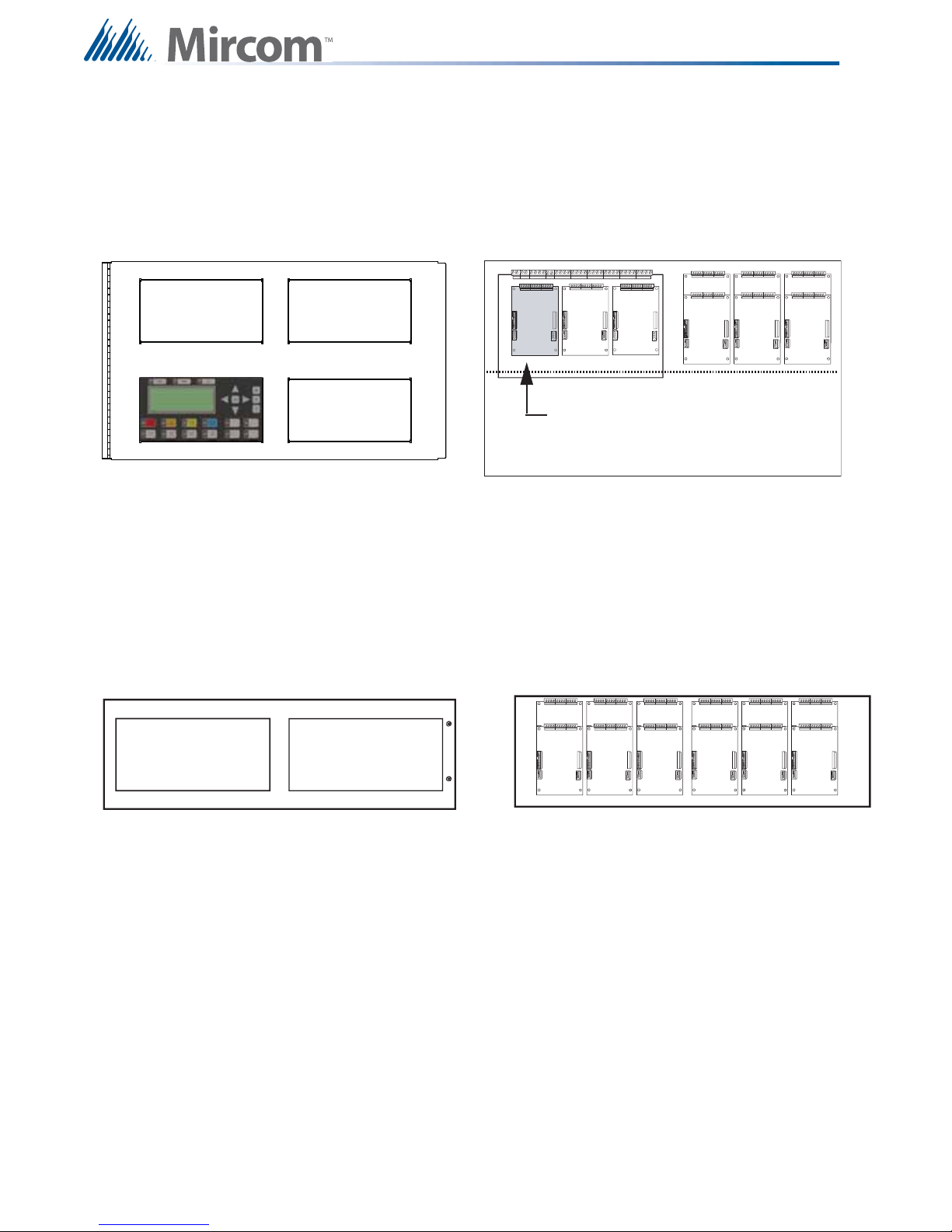
Display and Adder Modules Mounting Locations
Slot is reserved for PR-300 or UDACT300A. If not required, this slot can be used
to mount any of the adder modules.
Cutout to mount
display module
Cutout to mount
display module
6.3 FX-2009(S)-12DS Large Main Chassis
Mounts and occupies four display positions in BB-5008 or BB-5014 Enclosures, and supports
two display modules and nine adder modules.
Exterior View Interior View
Cutout to mount
display module
Cutout to mount
display module
Cutout to mount
display module
231
FX-2000 Main Board
6.4 ECX-0012 Expander Chassis for FX-2009-12DS
Mounts and occupies two display positions in BB-5008 or BB-5014 Enclosures, and supports
two display and 12 adder modules.
Exterior View Interior View
56
56
34
4
789
2
1
789101112
26
Page 30
Display and Adder Modules Mounting Locations
Inside Chassis for mounting adder
modules. Three modules can be
mounted over the main re alarm
board and six above the main re
alarm board stacked three over
three.
Three adder modules
mounted over main re
alarm board.
Main Fire Alarm Board
3
4
5
6
7
8
9
2
1
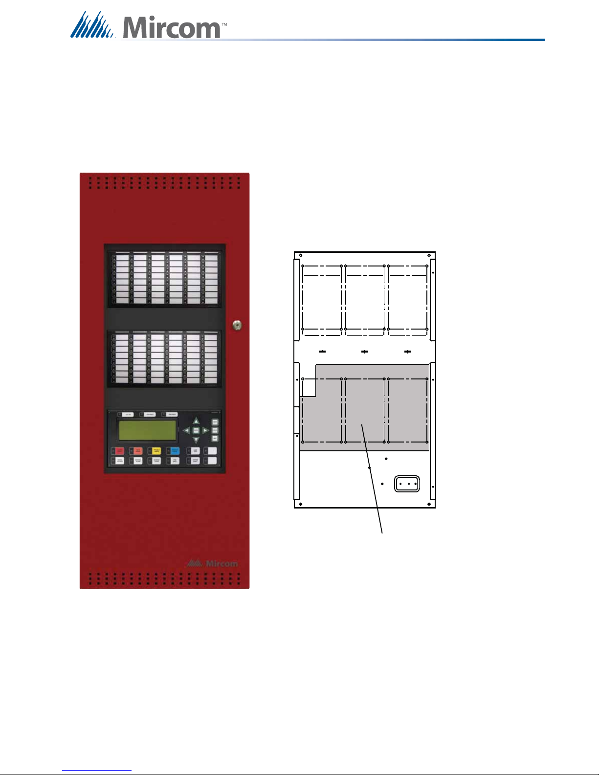
6.5 Mounting the Boards to the BBX-1024XTChassis
The main board is mounted to the chassis and is shipped out this way. Mounts up to 9 adder modules
and one display module such as RAX-1048TZDS Programmable 48 Zone and Trouble LED display
module, IPS-2424DS Programmable Input Switches module and FDX-008W Fan Damper module.
Figure 13 FX-2003-12XT in a BBX-1024XT Enclosure
27
Page 31

6.5.1 Adder Modules
CONNECT RIBBON
CABLE FROM P1
TO FIRE ALARM
CONTROL PANEL
POLARITY
REVERSAL
ALARM
POLARITY
REVERSAL
SUPV
CITY
TIE
+ | - + | - + | -
JW4
P1 P2
Each adder module occupies one module slot and mounts inside the following chassis:
• FX-2003-6DS/FX-2003-12DS/FX-2003-12XT/FX-2003-12XTDS Chassis
• FX-2017-12DS Mid-size Main Chassis and FX-2009-12DS Large Main Chassis
• ECX-0012 Expander Chassis for FX-2009-12DS
Display and Adder Modules Mounting Locations
ALC-198S
Single Intelligent
Analog Loop
Controller Module
SGM-1004A
Four NAC Circuit
Module
6.5.2 Display Modules
Each display module occupies one display position and mounts to the display cutouts on the
following chassis:
• FX-2003-6/FX-2003-12 Compact Main Chassis
• FX-2003-6DS/FX-2003-6DS-16LED/FX-2003-12DS Compact Main Chassis
• FX-2003-12XT/FX-2003-12XTDS Mid-size Main Chassis
• FX-2017-12DS Mid-size Main Chassis
• FX-2009-12DS Large Main Chassis
• ECX-0012 Expander Chassis for FX-2009-12
These modules can also be mounted in the standard BB-5000 cutouts (with brackets), and the
BBX-1000 enclosures (requires RAX-LCD as a driver).
ALC-396S
Dual Intelligent
Analog Loop
Controller Module
RM-1008A
Eight Relay
Circuit Module
ALC-H16
Hardwire Loop
Controller Module
UDACT-300A
Digital Alarm
Communicator
Module
DM-1008A
Eight Initiating
Circuit Module
PR-300
Polarity
Reversal/ City
Tie Module
RAX-1048TZDS
Programmable Zone LED
Annunciator Module
RAX-1048TZDS
Programmable Zone LED
Annunciator Module
28
IPS-2424DS
Programmable Input
Switches Module
FDX-008W
Fan Damper Module
OFF AUTO ON TROUBLE OFF AUTO ON TROUBLE OFF AUTO ON TROUBLE OFF AUTO ON TROUBLE
OFF AUTO ON TROUBLE OFF AUTO ON TROUBLE OFF AUTO ON TROUBLE OFF AUTO ON TROUBLE
Page 32

7.0 Module Settings
MAIN FIRE ALARM BOARD
FIELD WIRING TERMINALS
P9
P8
F1
P 10 P1 1 P12 P1 3
+ BDG- +BAT-
P7
JW1
P4
JW4
P14
P3
JW2
JW3
P5
P6
i
7.1 Main Fire Alarm Modules (MD-764 Part of Main Chassis)
JW1 Remove jumper if a PR-300 or UDACT-300A is installed.
JW2 to JW4 Jumpers are factory set and should not be changed.
P3 Black RS-485 Connector connects to the Adder Loop ALC-198S, ALC-396S
or ALC-H16 if used (Address Loops 3, 4, etc)
P4 Connector for PR-300 module or UDACT-300A.
P6 Connector for first eight conventional hardwire circuit adder modules (Loop 0).
P5 Connector for next eight conventional hardwire circuit adder modules (Loop1).
P7 White BDM Connector for factory use only.
P8 Power Connector for Adder Modules.
P9 RS-232C for printer or CRT monitor.
P10, P11 Factory connection to bridge rectifier.
P12, P13 Connection to 24VDC battery. Observe correct polarity
Module Settings
P14 Connector for display module.
F1 20 Amp slow blow non-replaceable fuse.
TO CONFIGURE THE FIRE ALARM PANEL USE THE RS-485 CONNECTOR P4 OF THE
LAST ADDER LOOP CONTROLLER MODULE INSTALLED.
Figure 14 Main Fire Alarm Board
Note: To enable communication from the Main Module to all of the Adder Modules, it is
necessary to add a Continuity Jumper on the last Adder Module in a chain (see
the appropriate Module Settings section to verify the location of the Continuity
Jumper on a particular Circuit Adder Module). Only the last circuit adder module
should have a jumper plug on its continuity jumper; all others must be left without
a jumper plug.
29
Page 33

Module Settings
MAIN FIRE ALARM SUPER BOARD
FIELD WIRING TERMINALS
P9
P8
F1
P 10 P1 1 P12 P1 3
+BDG- +BAT-
P7
JW1
P4
JW4
P14
P3
JW2
JW3
i
7.2 Main Fire Alarm Super Module (MD-757 Part of “S” Version
Main Chassis)
This super main board does not have any addressable loops on it. For an addressable loop,
adder boards are required.
JW1 Remove jumper if a PR-300 or UDACT-300A is installed.
JW2 to JW4 Jumpers are factory set and should not be changed.
P3 Black RS-485 Connector connects to the Adder Loop ALC-198S,
ALC-396S or ALC-H16 if used (Address Loops 3, 4, etc)
P4 Connector for PR-300 module or UDACT-300A.
NO HARDWIRE CIRCUIT ADDER MODULES ARE CONNECTED TO
THIS MAIN FIRE ALARM SUPER MODULE
P7 White BDM Connector for factory use only.
P8 Power Connector for Adder Modules.
P9 RS-232C for printer or CRT monitor.
P10, P11 Factory connection to bridge rectifier.
P12, P13 Connection to 24VDC battery. Observe correct polarity
P14 Connector for display module.
F1 20 Amp slow blow non-replaceable fuse.
TO CONFIGURE THE FIRE ALARM PANEL USE THE RS-485 CONNECTOR P4 OF THE
LAST ADDER LOOP CONTROLLER MODULE INSTALLED.
Figure 15 Main Fire Alarm Super Module (MD-757 Part of “S” Version Main Chassis)
Note: To enable communication from the Main Module to all of the Adder Modules, it is
necessary to add a Continuity Jumper on the last Adder Module in a chain (see
30
the appropriate Module Settings section to verify the location of the Continuity
Jumper on a particular Circuit Adder Module). Only the last circuit adder module
should have a jumper plug on its continuity jumper; all others must be left without
a jumper plug.
Page 34

7.2.1 DSPL-420 Main Display Module
i
i
P1 Cable connects to P14 of main fire alarm module
P2 Connection to P1 of any adder display module if used.
Figure 16 DSPL-420 Main Display Module
Module Settings
Note: The main display module comes with slide-in paper labels including both English
and French slide-ins, and laser printer-compatible blanks for zone labelling.
7.2.2 Optional DSPL-420-16TZDS Display Module
P1 Cable connects to P14 of main fire alarm module
P2 Connection to P1 of any adder display module if used.
Figure 17 DSPL-420-16TZDS Main Display Module with 16 Zone LEDs
Note: The main display module comes with slide-in paper labels including both English
and French slide-ins, and laser printer-compatible blanks for zone labelling.
31
Page 35

7.3 RAX-1048TZDS Zone Display Module
P
2
P
1
i
P1 Cable connects to P2 of previous display module.
P2 Cable connects to P1 of next display module.
Module Settings
Figure 18 Zone Display Module (RAX-1048TZDS)
7.4 IPS-2424DS Programmable Input Switches Module
P1 Cable connects to P2 of previous display module.
P2 Cable connects to P1 of next display module.
P
2
ZONE
BYPA
SS
#1
ZONE
BYPA
SS
#2
ZONE
BYPA
SS
#3
ZONE
BYPA
SS
#4
P
1
ZONE
BYPA
SS
#5
ZONE
BYPA
SS
#6
ZONE
BYPA
SS
#7
ZONE
BYPA
SS
#8
ZONE
BYPA
SS
#9
ZONE
BYPA
SS
#10
ZONE
BYPA
SS
#11
ZONE
BYPA
SS
#12
ZONE
BYPA
SS
#13
ZONE
BYPA
SS
#14
ZONE
BYPA
SS
#15
ZONE
BYPA
SS
#16
ZONE
BYPA
SS
#17
ZONE
BYPA
SS
#18
ZONE
BYPA
SS
#19
ZONE
BYPA
SS
#20
ZONE
BYPA
SS
#21
ZONE
BYPA
SS
#22
ZONE
BYPA
SS
#23
ZONE
BYPA
SS
#24
Figure 19 IPS-2424DS Programmable Input Switches Module.
Note: The zone display modules comes with laser printer-compatible slide-in paper
labels for zone labelling.
32
Page 36

7.5 Fan Damper Control Display Module (FDX-008W/WKI)
OFF AUTO ON TROUBLE
PARKING GARAGE #1,
FANS 1, 2 , 3
There are two models of the Fan Damper Control Display modules available. The FDX-008W
provides switch control and LED indication of 8 fan damper zones. The FDX-008WKI provides
switch control of 7 fan damper zones with the eighth zone activated by keyswitch. LED
indication is provided for all 8 fan damper zones on the FDX-008WKI. Both the FDX-008W
and the FDX-008WKI are used in conjunction with a FX-2000 Fire Alarm Control Panel.
Module Settings
Figure 20 Fan Damper Control Display Module (FDX-008W/WKI)
7.5.1 Fan Damper Operation
The FDX-008W Fan Damper Control Display module has eight configurable output circuits,
each with a three position switch. The FDX-008WKI operates in the same manner as the FDX008W except zone 8 is controlled by a remote keyswitch. Each switch has an ON and OFF
position, plus an AUTO position. If the switch is placed in the AUTO position, the white AUTO
LED will illuminate steady and the output will activate as programmed or configured. The
output can be manually turned ON or OFF by placing the switch in the ON or OFF position,
respectively.
Basically each switch can be configured to operate multiple fans or dampers. For each switch,
there are 3 operations provided; outputs to turn ON, same outputs to turn OFF and inputs to
bypass.
An example of the most common use of the FDX-008W or FDX-008WKI Fan Damper Control
Display module is to operate exhaust fans and confirm fan operation (via monitor modules).
See FDX-008W Block Diagram on the next page for a block diagram of fan and monitor set up.
7.5.2 Example
As shown in the figure to the right, Parking Garage #1 has 3
exhaust fans. The three position switch is configured to operate
(to turn ON) fans 1, 2 and 3 in stairwell #1. The switch is set in the
AUTO position. Upon activation (via alarm or some other
programmed trigger) with the switch in AUTO, the 3 fans (1,2, and
3) in stairwell #1 are turned ON automatically. Monitor modules in
the Parking Garage #1 detect that all 3 fans are operating,
therefore the ON LED will illuminate steadily. If one of the fans did
not turn ON (due to malfunction), the ON LED will flash. The TRBL (trouble) LED will illuminate
33
Page 37

Module Settings
OFF AUTO ON TROUBLE
FX-2000 FIRE
ALARM PANEL
FANS
OUTPUT MODULES
MONITOR MODULES
FDX-008W/WKI FAN/DAMPER CONTROL MODULE
i
i
steady amber based on feedback from the monitor module that one or more of the fans is not
working.
ON LED shows steady for all outputs operating and confirmed.
OFF LED shows steady for all outputs NOT operating and confirmed.
TRBL LED shows steady for one or more outputs NOT operating and confirmed.
Figure 21 FDX-008W Block Diagram of Fan and Monitor Setup
Note: A bypass function always has priority, so that if a circuit is bypassed by moving
the switch manually or by loop bypass (FX-2000 Fire Alarm Panel), no other
action will operate this switch other then again moving the switch manually or by
un-bypassing the loop.
Before mounting the FDX-008WKI module, if a keyswitch is to be connected, wire the
keyswitch to terminals at TS1 as shown in Figure 22 on page 35.
Note: There are also terminals located behind TS1 on the other side of the board for
the convenience of wiring the keyswitch. The last fan damper zone in the bottom
right position of the FDX-008WKI is controlled by the keyswitch.
34
Page 38

Module Settings
OFF AUTO ON TROUBLE
OFF AUTO ON TROUBLE
OFF AUTO ON TROUBLE
OFF AUTO ON TROUBLE
OFF AUTO ON TROUBLE
OFF AUTO ON TROUBLE
OFF AUTO ON TROUBLE
OFF AUTO ON TROUBLE OFF AUTO ON TROUBLE
TS1
P2
TERMINALS AT TS1 ARE WIRED TO A KEYSWITCH.
NOTE: IF FAN DAMPER MODULE IS MOUNTED TO
THE DOOR USE TERMINALS LOCATED AT THE
BACK OF THIS BOARD, BEHIND TS1.
P1
KEYSWITCH
CONTROLLED
CONNECTS TO
PREVIOUS DISPLAY
MODULE P2
Mount the FDX-008W and FDX-008WKI Fan Damper Control Display modules in any position
on the front part of the FX-2000 chassis.
Figure 22 FDX-008WKI Fan Damper Control Display Module
35
Page 39

7.6 DM-1008A Hardwire Detection Adder Module
P1
P3
P4
FI ELD WIRI NG TERMINALS
P2
JW5
JW4
JW3
JW2
JW1
Data cable to P6 or P5 of
main fire alarm module or to
P12 or P13 of hardwire
loop controller module, or
previous adder module
Powe r connect or t o P8 of
main fire alarm mod ule,
or to P2 of ha rdwire lo op
controller module, or to
previou s adder module
Data connector for
next adder module
Powe r con nect or for
next adder module
i
JW1 Install jumper for Class A (Style D) operation of initiating circuits 1 and 2.
JW2 Install jumper for Class A (Style D) operation of initiating circuits 3 and 4.
JW3 Install jumper for Class A (Style D) operation of initiating circuits 5 and 6.
JW4 Install jumper for Class A (Style D) operation of initiating circuits 7 and 8.
Module Settings
JW5
Remove continuity jumper if there are any more adder modules installed.
Figure 23 Hardwire Detection Adder Module (DM-1008A)
Note: For Class A (Style D) operation the FX-2000 must be configured as Class A via
the configuration program.
36
Page 40

7.7 SGM-1004A Hardwire NAC Signal Adder Module
i
JW1 Remove continuity jumper if this is not the last adder module installed.
JW2 Jumper pins for bell cut or isolators on Zone 1.
JW3 Jumper pins for bell cut or isolators on Zone 2.
JW4 Jumper pins for bell cut or isolators on Zone 3.
JW5 Jumper pins for bell cut or isolators on Zone 4.
JW11 For basic operation do not wire these terminals.
Module Settings
J11
ZONE 4
1 2 3
JW5
ZONE 3
JW4
ZONE 2
JW3
ZONE 1
FIELD WIRING TERMINALS
JW2
GREEN SIGNAL LEDs
Figure 24 Hardwire NAC Signal Adder Module (SGM-1004A)
Data cable to P6 or P5 of
main fire alarm module
or to previous adder module
P2
Data connector for
next adder module
JW1
P1
P4
Power connector to P8 of
main fire alarm module,
or to previous adder module
Power connector for
next adder module
P3
7.7.1 SGM-1004A Components
There are four green LEDs on the board, one for each signal zone. The LED will illuminate or
flash following the NAC signal rate sent to its zone. It will be off when the system is normal and
they will illuminate when a NAC signal zone is activated. The LED does not reflect what is
happening on the NAC signal zone, just that it is receiving data to activate that NAC signal
zone.
Note: Jumpers JW2, JW3, JW4 and JW5 are positioned on pins 2 and 3 (right two pins
with board orientation as shown above) from factory.
37
Page 41

7.7.2 SGM-1004A Operation
!
!
There are three modes of operation for this module. The basic mode of operation does not
involve any bell cut relay or isolators connected to the signal zones. For this case, leave
jumpers JW2, JW3, JW4 and JW5 as they come on pins 2 and 3, and do not make any
connection to terminal block J11. The second mode provides bell cut operation which allows
the silencing of the bells. The third mode is used when isolators are to be connected to the
signal circuits. For further information on bell cut relays or isolators, please refer to the specific
fire alarm panel manual or the isolator instruction manual.
7.7.3 SGM-1004A Jumpers for the Bell Cut Mode
JW2 Place jumper over pins 1 and 2 for the ability to remotely silence the bells on
Zone 1.
JW3 Place jumper over pins 1 and 2 for the ability to remotely silence the bells on
Zone 2.
JW4 Place jumper over pins 1 and 2 for the ability to remotely silence the bells on
Zone 3.
JW5 Place jumper over pins 1 and 2 for the ability to remotely silence the bells on
Zone 4.
Module Settings
JW11 Wire these terminals to a bell cut relay (for details see QRM-1001 Bell Cut
Module Installation and Operating Instructions, LT-666).
Attention: Discard jumpers on zones that are not configured for bell cut.
7.7.4 SGM-1004A Jumpers for the Isolator Mode
JW2 Place jumper over pins 2 and 3 for the ability to connect an isolator on Zone 1.
JW3 Place jumper over pins 2 and 3 for the ability to connect an isolator on Zone 2.
JW4 Place jumper over pins 2 and 3 for the ability to connect an isolator on Zone 3.
JW5 Place jumper over pins 2 and 3 for the ability to connect an isolator on Zone 4
JW11 Wire these terminals to an alarm relay. These may be tapped if more signal
modules are used in this manner.
Attention: Discard jumpers on zones that are not configured for isolators.
38
Page 42

7.8 RM-1008A Hardwire Relay Adder Module
P1
P3
P4
FIELD WIRING TERMINALS
P2
JW1
FIELD WIRING TERMINALS
3 2 1
3 2 1
3 2 1
3 2 1
3 2 1
3 2 1
3 2 1
3 2 1
JP1
JP2
JP3
JP4
JP5
JP6
JP7
JP8
I1
I2
I3
I4
I5
I6
I7
I8
P2 Data cable to P6 or P5 of main fire alarm module, or to P12 or P13 of Hardwire
loop controller module, or to previous adder module.
P1 Data connector for next adder module.
P4 Power connector to P8 of main fire alarm module, or to P2 of Hardwire loop
controller or to previous adder module.
P3 Power connector for next adder module.
JW1 Remove continuity jumper if there are any more adder modules installed. If this
is the last module installed, leave JW1 on.
JP1-JP8 Move jumpers from pins 1 and 2 to 2 and 3 to connect relay commons between
two or more relays.
.
Module Settings
Figure 25 Hardwire Relay Adder Module (RM-1008A)
39
Page 43

7.9 Polarity Reversal and City Tie Module (Model PR-300)
i
Module Settings
+ | - + | - + | -
ALARM
SUPV
TIE
REVERSAL
REVERSAL
CITY
POLARITY
POLARITY
P1 P2
JW4
Mounting hole for
#6-32 screws
Mounting hole for
#6-32 screws
Figure 26 Polarity reversal and city tie module
The following hardware configuration must be performed before installing the PR-300.
P1 Cable connects to P5 on the FX-2000 Main Fire Alarm Board
P2 P2 is for connecting the UDACT-300A if both PR-300 and UDACT-300A are
installed on the FX-2000.
JW4 If the PR-300 is used this is the last module jumper. JW1 on the main board
should be removed and JW4 on the PR-300 should be set. If both PR-300
and UDACT-300A are installed, then JW1 on the main board and JW4 on
the PR-300 should be removed.
Table 9 PR-300 jumper settings
The Alarm Transmit signal to the PR-300 can be programmed to turn OFF when signal silence
is active. This allows the City Tie Box to be manually reset. On subsequent alarms the
silenceable signals will resound and the City Tie Box will be retriggered. Please refer to the
Configurator for more information.
The Trouble Transmit signal to the PR-300 can be programmed to delay AC power fail. Please
refer to the Configurator for more information.
Note: Jumper JW1 on the FX-2000 main fire alarm board must be removed if a city tie
module is installed.
40
Page 44

7.10 UDACT-300A Main Board
There are two jumpers on the UDACT-300A which are used for operation/configuration
purposes. Jumper JW1 is used to reset the default passcode. Jumper JW2 is required for
configuring
connections, pushbutton and LEDs. Table 2 following, provides a description of the user items
on the UDACT-300A.
the UDACT-300A. Refer to Figure 22 below for location of jumpers, cable
SYSTEM NORMAL
13:21 MON 2015-08-03
Module Settings
CONNECT RIBBON
CABLE FROM P1
TO MIRCOM FIRE
ALARM CONTROL
PANEL
Figure 27 UDACT-300A Board Layout
Table 10 UDACT-300A Cable Connectors and Miscellaneous
Cable Connector Function
P1 Ribbon Cable for connecting to P4 of FX-2000 FACP main board.
P2 RS-232C/RS-485 Connection for computer configuration.
U18 Connector for CFG-300 Configuration Tool
Lamp Test button Connector for CFG-300 Configuration Tool
UR1 Potentiometer This potentiometer is for adjustment of the CFG-300 LCD contrast.
41
Page 45

Module Settings
i
The following table lists all the LEDs located on the UDACT-300A board and states the
function of each LED.
Table 11 UDACT-300A List of LEDs and their Functions
Cable Connector Function
Relay Line 1 Located below Line 1 terminal block. When Line 1 relay is energized, this green
LED will illuminate
Relay Line 2 Located below Line 2 terminal block. When Line 2 relay is energized, this green
LED will illuminate.
RS-485 Status LED for communication, will flash when RS-485 communication is
active.
Common Trouble Steady amber for any troubles on the Fire Alarm panel or UDACT-300A.
CPU Fail Steady amber for any on board CPU trouble.
Telephone Line 1 Telephone status indicator LED; Red when the line is in use, Amber when there
is a line trouble.
Telephone Line 2 Telephone status indicator LED; Red when the line is in use, Amber when there
is a line trouble.
Power ON Green LED is ON steady when power is supplied to the board.
The following table lists the user jumpers available on the UDACT-300A and their functions.
The following table lists the user jumpers available on the UDACT-300A and their functions..
Table 12 UDACT-300A List of Jumpers for Operation and Configuration
Cable
Function
Connector
JW1 Normally open. Place jumper here and power down the UDACT-300A by disconnecting
P1 or power down the fire alarm panel (AC and Batteries), then power back to revert to
default passcode. After reset, remove the jumper. Leave normally open.
JW2 Normally open to BLOCK remote configuration via modem, PC with a UIMA converter
module or using the LCD and keypad at the UDACT-300A. Place jumper here to
ALLOW any type of configuration. Remove jumper once configuration is complete.
Note: Can be installed with the PR-300 City Tie but not in the same location. If using
this configuration the PR-300 must be installed on the left and it is recommended
that the UDACT-300A be installed in the middle, although it can be installed on
the right if needed.
See the UDACT-300A Installation and Operation Manual (LT-888) for more information.
42
Page 46

Module Settings
7.11 ALC-198S Single Intelligent Analog Loop Controller Module
The ALC-198S Single Intelligent Analog Loop Controller module provides a single
addressable loop. It may be mounted over the main chassis of the FX-2000 Fire Alarm Panel
or on any chassis which supports adder boards. Refer to Module Mounting Locations View
#2 on page 24. The module is mounted using four #6 screws and (if necessary) four 1 1/2"
spacers.
Power The power is supplied to the board via cable from the main chassis board
or from the previous loop controller module into the P1 Power IN connector.
The P2 Power OUT connector is connected to the next loop controller
module or other adder module. Two power cables are supplied with the
module.
RS-485 The RS-485 cable comes attached at P3 and is connected to the main
chassis board or from the previous loop controller module or other adder
board. The RS-485 OUT at P4 is connected to the next loop controller
module if used or left without connection.
DIP switches The dip switches are used to set the address of the board. The address is
binary, with the SW-1 switch as the lowest significant digit and OFF being
active. For example an address of two is SW-1 ON, SW-2 OFF, and all the
other dip switches SW-3 to SW-8 ON. Refer to Appendix E: DIP Switch
Settings Summary on page 96 for more information.
Loop 1 This is the addressable loop for all initiating devices. Wire the loop as
shown in Field Wiring on page 49.
Jumpers A jumper is provided at JW2 for normal operation. To reset the board the
jumper is left at JW2 and the pins at position JW1 are shorted momentarily.
BDM Port This connection is for factory use only.
43
Page 47

Module Settings
1
8
RS-485
CABLE
RS-485
ADDRESS
DIP
SWITCH
BDM
PORT
JW2 - A
JUMPER IS
PLACED HERE
TO ENABLE
WATCHDOG
TIMER. THIS
IS JUMPER=S
NORMAL
LOCATION.
JW1 - JUMPER IS
PLACED HERE TO
RESET HARDWARE
POWER
CABLE
(OUT)
POWER
CABLE
(IN)
LOOP A
IN
OUT
+ - + -
B
A
DIP SWITCHES ARE FOR
THIS BOARD=S ADDRESS.
SW-1 IS THE LEAST
SIGNIFICANT DIGIT (BINARY).
ACTIVE POSITION IS OFF.
JW3 - JUMPER
FROM JW2 IS
PLACED HERE TO
BYPASS
WATCHDOG FOR
FACTORY
DOWNLOADING
USING BDM
P3
P4
P5
P1
P2
SHIELD
Figure 28 ALC-198S Single Intelligent Analog Loop Controller Module
Mount the ALC-198S Single Intelligent Analog Loop Controller module as described in the
section Display and Adder Modules Mounting Locations on page 25. The module may be
mounted over the main chassis board or in any position that an adder module is mounted.
44
Page 48

Module Settings
7.12 ALC-396S Dual Intelligent Analog Loop Controller Module
The ALC-396S Dual Intelligent Analog Loop Controller module provides a two addressable
loops. It may be mounted over the main chassis of the FX-2000 Fire Alarm Panel or on any
chassis that supports adder boards. Refer to page Module Mounting Locations View #2 on
page 24 for mounting applications. The module is mounted using four #6 screws and (if
necessary) four 1 1/2" spacers.
Power The power is supplied to the board via cable from the main chassis board
or from the previous loop controller module into the P1 power in connector.
Connect the P2 power out connector to the next loop controller module or
other adder module. Two power cables are supplied with the module.
RS-485 The RS-485 cable comes attached at P3 and is either connected to the
main chassis board or connected from the previous loop controller module
or other adder board. If the next loop controller module is used, connect the
RS-485 out at P4 to the next loop controller module; if it is not used, leave
without connection.
DIP switches Use the DIP switches to set the binary address of the board. SW-1 is the
lowest significant digit and OFF is active. For example, an address of two
would be created by turning SW-1 on, SW-2 off and DIP switches SW-3 to
SW-8 on. Refer to Appendix E: DIP Switch Settings Summary on page 96
for DIP switch settings.
Loop 1 This is the addressable loop for all initiating devices. Wire the loop as
shown in Single Loop Terminal Connections - Class B on page 54 or Single
Loop Terminal Connections - Style 7 on page 55 and Single Loop Terminal
Connections - Style 6 on page 56.
Loop 2 This is the addressable loop for all initiating devices. Wire the loop as
shown in Single Loop Terminal Connections - Class B on page 54 or Single
Loop Terminal Connections - Style 7 on page 55 and Single Loop Terminal
Connections - Style 6 on page 56.
Jumpers A jumper is provided at JW2 for normal operation. To reset the board, leave
the jumper at JW2 and momentarily short the pins at position JW1.
BDM Port This connection is for factory use only.
45
Page 49

Module Settings
1
8
RS-485
CABLE
RS-485
ADDRESS
DIP
SWITCH
BDM
PORT
JW2 - THE
JUMPER IS
KEPT HERE
FOR
NORMAL
OPERATION
JW1 - PINS ARE
SHORTED
MOMENTARILY TO
RESET
HARDWARE
JW3 - JUMPER
FROM JW2 IS
PLACED HERE TO
BYPASS
WATCHDOG FOR
FACTORY
DOWNLOADING
USING BDM
POWER
CABLE
POWER
CABLE
LOOP A
DIP SWITCHES ARE FOR
THIS BOARD=S ADDRESS.
SW-1 IS THE LEAST
SIGNIFICANT DIGIT (BINARY).
ACTIVE POSITION IS OFF.
+ - + -
B
A
P3
P2
P1
P5
P4
LOOP B
+ - + -
B
A
SHIELD
i
Figure 29 ALC-396S Dual Intelligent Analog Loop Controller Module
Mount the ALC-396S Dual Intelligent Analog Loop Controller module as shown in Module
Mounting Locations View #2 on page 24. The module may be mounted over the main chassis
board or in any position that an adder module is mounted.
Note: There are two addressable loops present on this board (ALC-396S) that are
wired in the same manner as shown in the wiring diagrams beginning with Main
Fire Alarm Module Terminal Connections on page 49. Although these drawings
show only Loop 1, Loop 2 is wired in the same way as Loop 1 is. Note that Loop
1 and Loop 2 do not have to be wired in the same class, such as Class A or
46
Class B or Style 7. Therefore Loop 1 may be wired as Class A and Loop 2 may
be wired as Class B.
Page 50

7.13 ALC-H16 Hardwire Loop Controller Module
The ALC-H16 Hardwire Loop Controller module provides an interface in order to add 16
conventional adder boards. This board may be mounted over the main chassis of the FX-2000
Fire Alarm Panel or on any chassis which supports adder boards. Refer to page Module Mounting
Locations View #2 on page 24 for mounting applications. Mount the module using four #6 screws
and (if necessary) four 1 1/2" spacers.
Power The power is supplied to the board via cable from the main chassis board
or from the previous loop controller module into the P1 power in connector.
Connect the P2 power out connector to the next loop controller module or
other adder module. Two power cables are supplied with the module.
RS-485 The RS-485 cable comes attached at P3 and is either connected to the
main chassis board or connected from the previous loop controller module
or other adder board. If the next loop controller module is used, connect the
RS-485 out at P4 to the next loop controller module; if it is not used, leave
without connection.
Jumpers A jumper is provided at JW2 for normal operation. To reset the board, leave
the jumper at JW2 and momentarily short the pins at position JW1.
BDM Port This connection is for factory use only.
P13 and P12
Connectors
Connect the P13 connector (via ribbon cable included with this module) to
the first module of the first group of eight conventional adder modules.
Connect the P12 connector (via ribbon cable included with this module) to
the first module of the second group of eight conventional adder modules
Module Settings
47
Page 51

Module Settings
A
.
P12 IS USED TO CONNECT SECOND GROUP OF 8 ADDER MODULES
P13 IS USED TO CONNECT FIRST GROUP OF 8 ADDER MODULES
RS-485
P12
CAB LE
DDRESS
DIP
SWI TCH
RS- 4 8 5
P13
P4
ON
1
8
D I P SWI TCH ES ARE FO R
THIS BOARD= S ADDRESS.
SW- 1 IS TH E LEA ST
SIGNIFICANT DIGIT (BINARY).
ACTIVE POSITION IS OFF.
JW3 - JUM PER
FROM JW2 IS
PLACED HERE TO
BYPASS
WATCH DOG FOR
FA C T O R Y
DOWNLOADING
USING BDM
P3
P2
POWER
CAB LE
(OUT)
POWER
CAB LE
(IN)
Figure 30 ALC-H16 Hardwire Loop Controller Module
Mount the ALC-H16 Hardwire Loop Controller module as shown on Module Mounting
Locations View #2 on page 24 and ECX-0012 Expander Chassis for FX-2009-12DS on
page 26. The module may be mounted over the main chassis board or in any position that an
adder module is mounted.
There is no wiring at the ALC-H16 Hardwire Loop Controller module, but there is wiring at the
16 standard conventional adder modules. For conventional hardwire circuit wiring refer to
Hardwire Detection Module (DM-1008A) Terminal Connections on page 57, Hardwire Signal
Module Terminal Connections on page 58, and Hardwire Relay Module Terminal
Connections on page 59 for the specific module you are wiring.
48
BDM PORT
JW3
JW1
JW2
JW2 - THE
JUM PER IS
KEPT HERE
FOR
NORMAL
OPERATION
P1
JW1 - PINS ARE
SH ORT ED
MOMENTARILY TO
RESET
H A RD W A RE
Page 52

8.0 Field Wiring
!
i
COM
-
RS485
NO
NC
COM
TROUBLE
NO
NC
COM
SIG GND
or COM(-)
NO
NC
ALARM
USE TWISTED SHIELDED PAIR.
22 AWG UP TO 2000 FT.
20 AWG UP TO 4000 FT.
SUPV.
+
S
RS-485 INTERFACE TO
ANNUNCIATORS AND
OTHER DEVICES
(POWER LIMITED)
NOT USED
MUST BE
CONNECTED TO A
LISTED POWER
LIMITED SOURCE
OF SUPPLY
COMMON TROUBLE
CONTACTS
28 VDC, 1 AMP
RESISTIVE LOAD
AUXILIARY COMMON
SUPERVISORY
CONTACTS
28 VDC, 1 AMP
RESISTIVE LOAD
AUXILIARY COMMON
ALARM CONTACTS
28 VDC, 1 AMP
RESISTIVE LOAD
S
8.1 Main Fire Alarm Module Terminal Connections
Wire devices to terminals as shown in Figure 31 below. See Wiring Tables and Information on
page 63. See Appendix A: Specifications on page 79 and Appendix B: Compatible Devices on
page 85 for compatible devices..
Attention: Do not exceed power supply ratings:
Main Chassis FX-2003-6DS and FX-2003-6DS-16LED total current for NAC
circuits is 5A max.
Main Chassis FX-2003-12DS, FX-2003-12XTDS, FX-2017-12ADS or FX-
2017S-12ADS total current for NAC circuits is 10A max.
Main Chassis FX-2009-12DS and FX-2009S-12DS: total current for NAC
circuits is 10A max.
Notes: The terminal blocks are "depluggable" for ease of wiring.
Field Wiring
All power limited circuits must use type FPL, FPLR, or FPLP power limited cable.
8.1.1 Main Fire Alarm Module Terminal Connections.
Figure 31 Main Fire Alarm Module Terminal Connections
49
Page 53

BELL, HORN, OR
STROBE
Legend: See Appendix A for compatible devices.
3.9K 1/2W ELR LISTED S5434
MODEL MP-300 MANUFACTURED
BY MIRCOM
IND2+ (Z)
IND2- (Z)
IND2- (Y/Z)
SUPERVISED INDICATING CIRCUIT #2
INDICATION
CIRCUIT 1
(POWER
LIMITED)
IND1+ (Z)
STYLE Z
(CLASS A)
WIRING
IND1- (Y/Z)
IND1+ (Y/Z)
IND2+ (Y/Z)
IND1- (Z)
INDICATION
CIRCUIT 2
(POWER
LIMITED)
INDICATING CIRCUITS 3 & 4
ARE NOT SHOWN
STYLE Y
(CLASS B)
WIRING
SUPERVISED INDICATING CIRCUIT #1
ANALOG
LOOP 2
CONNECTIONS
(LOOP 0 AND
LOOP1 ARE
INTERNAL
ADDRESSES
FOR FIRST 8
CARDS AND
SECOND 8
CARDS
RESPECTIVELY
+
4-WIRE
POWER
SUPPLY
-
+
AUX.
POWER
-
TRB
RTI
INTERFACE
TRL
ANALOG LOOP FIELD WIRING
(CLASS A OR B)
SEE ANALOG LOOP WIRING SECTION
CONNECTION TO MIRCOM RTI
REMOTE TROUBLE INDICATOR
(SEE RTI INSTALLATION
INSTRUCTION) BLK TOTRB+ BLU
TO TRL-RED & WHT TO AUX.
POWER COM+
END OF LINE RELAY
LISTED S3403
MODEL A77-716B
MANUFACTURED BY
SYSTEM SENSOR
2
3
41
6
5
+
-
+
-
TO
INITIATING
CIRCUIT
+
-
+
-
POWER
+
-
DETECTION
4-WIRE
DETECTION
DEVICE
AUXILIARY POWER
FOR REMOTE ANNUNCIATORS
24 VDC UNFILTERED
1.7 AMPS MAXIMUM
RTI
BLK
BLU
RED & WHT
LOOP 2
B
A
+
+
-
+
-
-
+
+
+
-
-
i
i
Field Wiring
NAC
NAC
Figure 32 Main Fire Alarm Module Terminal Connections (continued)
Notes: The terminal blocks are "depluggable" for ease of wiring.
All power limited circuits must use type FPL, FPLR, or FPLP power limited cable.
Notes: All power limited circuits must use type FPL, FPLR, or FPLP power limited cable.
Indicating (NAC) circuits are fully supervised and rated for 24 VDC unfiltered
50
1.7A max. Use wire size as stated in Table 15 NAC Circuit Wiring Table on
page 63.
Page 54

8.2 Analog Loop Wiring
i
8.2.1 Loop Terminal Connections - Class B
Field Wiring
FX-2000
MAIN FIRE ALARM BOARD
ANALOG
LOOP
CONNECTIONS
COM ( - )
LOOP 2
B
A
+
+
-
NAC
INDICATING
CI RCUI TS
4-WIRE
RESET TA B L E
SUPPLY
+
-
IND1 + (Y/Z)
IND1 + (Z)
IND1 - (Z)
IND1 - (Y/Z)
S
S
TWO WIRES
S
SO
F
M
C
M
2 Pair
s
C
s
Conventional Heat Sensors
and Manual Pull Stations
C
C
s
s
TWO WIRES
H
F
H
H
S
F
LEGEND
Addr essabl e Smo ke Detect or
S
wi th St andar d An alog Base
Addr essable Thermal Sensor
H
wi th St andar d An alog Base
Convent ional Smo ke Sensor
C
s
Addressable Manual
F
Pull Station
End -Of -Li n e- Resist o r
Combination
Horn /St robe
Addressable
Monit or Module
M
Addressable Supvr.
SO
Out pu t M odu le
Figure 33 Loop Terminal Connections - Class B
Notes: Terminal blocks are “depluggable” for ease of wiring.
All power limited circuits must use type FPL, FPLR, or FPLP power limited cable.
Loop wiring: maximum loop resistance is 40 ohms total. These lines are fully
supervised.
Observe in and out polarity when using module and base isolators.
51
Page 55

8.2.2 Loop Terminal Connections - Style 7
i
Field Wiring
TWO WIRES
FX-2000
MAIN FIRE ALARM BOARD
COM(-)
+
LOOP 2
ANALOG
LOOP
CONNECTIONS
4-WIRE
RESETTABLE
SUPPLY
AUXILIARY
POWER
SUPPLY
B
-
A
+
-
+
+
-
I
F
I
ADDRESSABLE
SMOKE DETECTOR
WITH ISOLATOR BASE
S
I
I
F
I
TWO WIRES
TWO WIRES
I
Conventional Heat Sensors
and Manual Pull Stations
M
C
I
s
I
H
ADDRESSABLE
THERMAL
SENSOR
WITH
ISOLATOR
BASE
STYLE 7: For Style 7 operation use isolator
bases for the detectors and use isolator modules
(front and back as shown in this diagram) for the
addressable pull stations, monitor modules, and
control modules
LEGEND
Addressable Smoke Detector
S
with Isolator Base
Addressable Thermal Sensor
H
with Isolator Base
Figure 34 Loop Terminal Connections - Style 7
Notes: All power limited circuits must use type FPL, FPLR, or FPLP power limited cable.
Isolators need to be close nipple connected to the device being protected.
Loop wiring: maximum loop resistance is 40 ohms total. These lines are fully
supervised.
52
Conventional Smoke Sensor
C
s
Addressable Manual Pull Station
F
Fault Isolator Module
I
Addressable Monitor Module
M
Page 56

8.2.3 Loop Terminal Connections - Style 6 (Formerly Class A)
F
4-WIRE
RESETTABLE
SUPPLY
+
-
AUXILIARY
POWER
SUPPLY
+
-
ADDRESSABLE
THERMAL SENSOR
ADDRESSABLE
SMOKE DETECTORS
FX-2000
ANALOG
LOOP
CONNECTIONS
F
LEGEND
Addressable Smoke Detector
Addressable Thermal Sensor
Addressable Manual Pull Station
F
Addressable Monitor Module
RO
TWO WIRES
TWO WIRES
B
A
+
-
+
-
LOOP 2
S
H
S
S
H
Addressable
Relay Output Module
M
M
M
RO
COM(-)
MAIN FIRE ALARM BOARD
Conventional 4-Wire Smoke
Detectors, Heat Sensors
and Manual Pull Stations
Field Wiring
Figure 35 Loop Terminal Connections - Style 6 (Formerly Class A)
53
Page 57

8.2.4 Single Loop Terminal Connections - Class B
Conventional Heat Sensors
and Manual Pull Stations
2 Pair
4-WIRE
RESETTABLE
SUPPLY
+
-
IND1 + (Y/Z)
IND1 + (Z)
IND1 - (Z)
IND1 - (Y/Z)
F
LEGEND
Addressable Smoke Sensor
with Standard Analog Base
Addressable Thermal Sensor
with Standard Analog Base
Conventional Smoke
Sensor
Addressable Manual
Pull Station
Combination
Horn/Strobe
Addressable
Monitor Module
Addressable Supvr.
Output Module
End-Of-Line-Resistor
TWO WIRES
TWO WIRES
S
H
S
C
s
C
s
C
s
F
F
H H
S
S
H
C
s
C
s
F
M
SO
M
TWO WIRES
M
SO
B
A
ANALOG
LOOP A
+
-
+
-
SHIELD
FX-2000
MAIN FIRE ALARM BOARD
ALC-198S SINGLE
LOOP MODULE
i
Field Wiring
Figure 36 Single Loop Terminal Connections - Class B
Notes: All power limited circuits must use type FPL, FPLR, or FPLP power limited cable.
54
Loop wiring: maximum loop resistance is 40 ohms total. These lines are fully
supervised.
Page 58

8.2.5 Single Loop Terminal Connections - Style 7
LEGEND
Ad dr essabl e Smo ke
Sensor with Isolator Base
Addressable Thermal
Sensor with Isolator Base
Conventional Smoke Sensor
Addressable Manual Pull Station
Fault Isolator Module
Conventional Heat Sensors
and Manu al Pull St ati on s
F
C
s
F
ADDRESSABLE
THERMAL SENSOR
WITH ISOLATOR
BASE
ADDRESSABLE
SMOKE DETECTOR
WITH ISOLATOR
BASE
F
C
s
Addressable Monit or Module
H
S
S
H
TWO WIRES
TWO WIRES
TWO WIRES
TWO WIRES
I
I
I
I
I
I
I
I
M
M
I
B
A
ANALOG
LOOP A
+
-
+
-
ALC-198S SINGLE
LOOP MODULE
STYLE 7: For Style 7 operation use isolator
bases for the detectors and use isolator modules
(front and back as shown in this diagram) for the
addressable pull stations, monitor modules, and
control modules
i
Field Wiring
Figure 37 Single Loop Terminal Connections - Style 7
Notes: All power limited circuits must use type FPL, FPLR, or FPLP power limited cable.
Isolators need to be close nipple connected to the device being protected.
Loop wiring: maximum loop resistance is 40 ohms total. These lines are fully
supervised.
55
Page 59

8.2.6 Single Loop Terminal Connections - Style 6
F
ADDRESSABLE
THERMAL SENSOR
ADDRESSABLE
SMOKE DETECTORS
F
LEGEND
Addr essabl e Smo ke Sensor
Addressable Thermal Sensor
Addressable Manual Pull Station
F
Addressable Monitor Module
TWO WIRES
S
S
H
Addressable Relay Output Module
S
H
M
M
RO
M
RO
B
A
+
-
+
-
ANALOG
LOOP A
ALC-198S SINGLE
LOOP MODULE
Conventional 4-Wire Smoke
Detectors, Heat Sensors
and Manual Pull Stations
i
Field Wiring
Figure 38 Single Loop Terminal Connections - Style 6
Notes: All power limited circuits must use type FPL, FPLR, or FPLP power limited cable.
Loop wiring: maximum loop resistance is 40 ohms total. These lines are fully
supervised.
56
Page 60

8.2.7 Detection Module (DM-1008A) Terminal Connections
SUPERVISORY OR
WATERFLO W
SWI TCH (N O)
HEAT DETECTOR
Legend: See Appendix B for compatible devices.
SMOKE DETECTOR
3.9K 1/ 2W ELR LISTED S5434
MODEL MP-300
MANUFACTURED BY MIRCOM
INI1+
INI1-
INI2+
INI2-
INI3+
INI3-
INI4+
INI4-
STY LE B/ D
INI2
STY LE B/ D
INI1
PULL STATION
STY LE B
( CLA SS B)
WIRING
STY LE B
( CLA SS B)
WIRING
STY LE D
( CLA SS A)
WIRING
SUPERVISED INITIATING CIRCUIT #2
(SUPERVISORY OR WATERFLOW ZONE)
(POWER LIMITED)
SUPERVISED INITIATING CIRCUIT #1
(ALARM ZONE) (POWER LIMITED)
SUPERVISED INITIATING CIRCUIT #3
( AL ARM ZO NE) SEE STYL E D N OTE ( PO WER LI M IT ED)
INI5+
INI5-
INI6+
INI6-
INI7+
INI7-
INI8+
INI8-
STY LE B/ D
INI4
STY LE B/ D
INI3
Style D Note: Initiating circuits in a series
FX-2000 must be either all Style B (Class B)
or Style D (Class A). If Style D is selected, the
number of circuits is cut in half.
i
Wire devices to terminals as shown in Figure 39. For further wiring information 8.8 Wiring
Tables and Information. For specifications 12.0 Appendix A: Specifications. For compatible
devices 13.0 Appendix B: Compatible Devices. Jumpers are required for Class A operation.
Field Wiring
Figure 39 Hardwire Detection Module (DM-1008A) Terminal Connections
Notes: Terminal blocks are “depluggable” for ease of wiring.
All power limited circuits must use type FPL, FPLR, or FPLP power limited cable.
Initiating circuits are fully supervised and rated for 22 VDC, 3 mA standby, 5 mV
ripple, 50 mA max alarm. They may be configured as required. The alarm
threshold is 21 mA. Maximum loop resistance is 100 ohms, 50 ohms per side.
All conventional hardwire initiating circuits are Compatibility ID "A".
57
Page 61

8.3 NAC Signal Module (SGM-1004A) Terminal Connections
IND2+ (Z)
IND2- (Z)
IND2- (Y/Z)
SUPERVISED INDICATING CIRCUIT #2
INDICATION
CIRCU IT 1
(POWER
LIMI TED)
IND1+ (Z)
STY LE Z
( CLA SS A)
WIRING
IND1- (Y/Z)
IND1+ (Y/Z)
IND2+ (Y/Z)
IND1- (Z)
INDICATION
CIRCU IT 2
(POWER
LIMI TED)
STY LE Y
( CLA SS B)
WIRING
SUPERVISED INDICATING CIRCUIT #1
IND4+ (Z)
IND4- (Z)
IND4- (Y/Z)
SUPERVISED INDICATING CIRCUIT #4
INDICATION
CIRCU IT 3
(POWER
LIMI TED)
IND3+ (Z)
STY LE Z
( CLA SS A)
WIRING
IND3- (Y/Z)
IND3+ (Y/Z)
IND4+ (Y/Z)
IND3- (Z)
INDICATION
CIRCU IT 4
(POWER
LIMI TED)
STY LE Y
( CLA SS B)
WIRING
SUPERVISED INDICATING CIRCUIT #3
Legend: See Appendix B for compatible devices.
SMOKE DETECTOR
3.9K 1/2W ELR LISTED S5434
MODEL MP-300
MANUFACTURED BY MIRCOM
i
Wire devices to terminals as shown in Figure 40. For further wiring information 8.8 Wiring
Tables and Information. For specifications 12.0 Appendix A: Specifications. For compatible
devices 13.0 Appendix B: Compatible Devices.
Field Wiring
Figure 40 Hardwire Signal Module Terminal Connections
Notes: The terminal blocks are “depluggable” for ease of wiring.
All power limited circuits must use type FPL, FPLR, or FPLP power limited cable.
SGM-1004A NAC circuits are fully supervised and rated for 24 VDC unfiltered
1.7A max. They must use wire size as stated in the wiring tables on page 63.
58
Page 62

8.4 Relay Module (RM-1008(A)) Terminal Connections
RLY 1
AUX RELAY 1
CONTACTS
28 VDC, 1 AMP
RESISTIVE LOAD
RLY 2
AUX RELAY 2
CONTACTS
28 VDC, 1 AMP
RESISTIVE LOAD
RLY 3
AUX RELAY 3
CONTACTS
28 VDC, 1 AMP
RESISTIVE LOAD
RLY 4
AUX RELAY 4
CONTACTS
28 VDC, 1 AMP
RESISTIVE LOAD
COM
RLY 5
NO
NC
AUX RELAY 5
CONTACTS
28 VDC, 1 AMP
RESISTIVE LOAD
RLY 6
AUX RELAY 6
CONTACTS
28 VDC, 1 AMP
RESISTIVE LOAD
RLY 7
AUX RELAY 7
CONTACTS
28 VDC, 1 AMP
RESISTIVE LOAD
RLY 8
AUX RELAY 8
CONTACTS
28 VDC, 1 AMP
RESISTIVE LOAD
COM
NO
NC
COM
NO
NC
COM
NO
NC
COM
NO
NC
COM
NO
NC
COM
NO
NC
COM
NO
NC
i
!
Relays are available as shown in Figure 41
Field Wiring
Figure 41 Hardwire Relay Module Terminal Connections
Notes: All relay circuits are power limited and must use type FPL, FPLR, or FPLP power
limited cable.
All relay circuits must be connected to a listed power limited source of supply.
Attention: Do not connect 120 VAC directly to these relays.
59
Page 63

8.5 Polarity Reversal and City Tie Module (PR-300) Wiring
i
Wire PR-300 Polarity Reversal and City Tie Module (if used) as shown in Figure 42 below.
Power Limited cable type FPL, FPLR or FPLP must be used.
For USA installation, the installer must use Atlantic Scientific (Tel: 407-725-8000), Model
#24544 Protective Device, or similar UL-Listed QVRG secondary protector, as shown.
For use in Canada, the Protective Device is not required but still recommended.
PR-300
+
CITY TIE LOCAL ENERGY
RATED - 24VDC FILTERED
TRIP COIL - 14 Ohms, 250mA,
5mV RIPPLE
-
POWER LIMITED
+
POLARITY REVERSAL ALARM
24VDC OPEN
12VDC AT 3.5mA
8mA MAX. SHORT
-
POWER LIMITED
+
POLARITY REVERSAL SUPV.
24VDC OPEN
12VDC AT 3.5mA
8mA MAX. SHORT
-
POWER LIMITED
1
2
S
1
2
S
1
PROTECTOR
UNPROCTECTEDUNPROCTECTED
PROCTECTOR
1
2
S
1
PROCTECTEDPROCTECTED
2
S
DIN RAIL CONNECTION
TO EARTH GROUND
1
+
USE A SHORTING WIRE
WHEN THE CITY TIE IS
-
NOT USED
+
-
CONFIRMS TO NEMA STANDARD
SB3-1969 INTENDED FOR
CONNECTION TO POLARITY
REVERSAL CIRCUIT OF A REMOTE
STATION RECEIVING UNIT HAVING
COMPATIBLE RATINGS
+
Field Wiring
2
S
1
2
2
S
1
2
-
POWER LIMITED CABLE TYPE
FPL, FPLR or FPLP MUST BE
USED FROM PR-300 TO
S
S
DIN RAIL CONNECTION
TO EARTH GROUND
PROTECTORS.
Figure 42 Polarity reversal and city tie module terminal connection
Notes: Either the PR-300's city tie or polarity reversal interface may be used, but not
both. The city tie interface is not power limited. Plug PR-300 ribbon cable (P1)
into connector (P4) of the FX-2000 main fire alarm module. Cut jumper (JW1) on
the PR-300 module in order to transmit a trouble condition to the monitoring
station. Remove jumper plug from jumper JW4 on the main fire alarm module.
The polarity reversal interface is power limited and must use type FPL, FPLR, or
FPLP power limited cable. For polarity reversal operation, short the city tie
connection.
60
Page 64

8.6 UDACT-300A Main Board Terminal Connections
i
Wire the two telephone lines to RJ31X Connector terminals as shown in Figure 43. The
UDACT-300A terminals are located on the top left hand corner of the board. If using a cellular
or wireless service, use the Line 2 interface connection only.
Field Wiring
1
23
76
8
BROWN
TTRR
Line 2 is Wired as shown for Line 1
TTRR
RED
GREEN
GREY
RES RESC.O. C.O.
LINE-1 LINE-2
RJ31X
4
5
TIP
RING
Public switch
Telephone company
wiring
TIP
RING
premise telephone
IF permitted
Figure 43 Telephone Line Wiring Diagram
Note: Most Authorities Having Jurisdiction (AHJ) do not allow the connection of
premise telephones. see specifications for more information.
UDACT-300A
61
Page 65

8.7 Power Supply Connections
P13
CONNECT GREEN
EARTH GROUND WIRE
TO MAIN MODULE PCB
MOUNTING SCREW.
N
G
GREEN
TO 24 VDC
BATTERY
BLACK
P11
P10
P12
+
BAT
RED
TO DEDICATED
BRANCH CIRCUIT
L
L
20 Amp
FAST ACTING FUSE
FUSE
!
The power supply is part of the main chassis. The ratings are outlined in Table 13.
Table 13 Power Supply Ratings
Field Wiring
Model Electrical Input
FX-2003-6DS & FX-20036DS-16LED Main Chassis
FX-2003-12DS, FX-200312XTDS,FX-2017-12ADS &
FX-2017S-12ADS Main
Chassis
FX-2009-12DS & FX-2009S12DS Main Chassis
Using proper wire gauge, connect as shown in Figure 44. For specifications see 12.0
Appendix A: Specifications.
Ratings
120 VAC, 60 Hz, 2A /
240VAC, 50hz, 1A
120 VAC, 60 Hz, 2A /
240VAC, 50hz, 1A
120 VAC, 60 Hz, 2A /
240VAC, 50hz, 1A
Power Supply
Total Current
6 amps maximum
12 amps maximum
12 amps maximum
Battery Fuse on Main
Module
Replace with 20 Amp, 1-1/4"
Fuse
Replace with 20 Amp, 1-1/4"
Fuse
Replace with 20 Amp, 1-1/4"
Fuse
Figure 44 Power Supply Connections
Caution: To prevent sparking, connect batteries after the system’s main A.C. power is
62
turned ON. Do not exceed power supply ratings.
Page 66

8.8 Wiring Tables and Information
i
i
Table 14 Wiring Table for Initiating Circuits
Wire Gauge Maximum Wiring Run to Last Device (ELR)
(AWG) ft. m
22 2990 910
20 4760 1450
18 7560 2300
16 12000 3600
14 19000 5800
12 30400 9200
Note: Maximum loop resistance should not exceed 100 Ohms.
Field Wiring
Main board NAC circuits are rated for 1.7 amps each. The SGM-1004A NAC circuits are rated
for 1.7 amps each.
Table 15 NAC Circuit Wiring Table
TOTAL
SIGNAL
LOAD
Amperes ft m ft m ft m ft m Ohms
0.06 2350 716 3750 1143 6000 1829 8500 2591 30
0.12 1180 360 1850 567 3000 915 4250 1296 15
0.30 470 143 750 229 1200 366 1900 579 6
0.60 235 71 375 114 600 183 850 259 3
0.90 156 47 250 76 400 122 570 174 2
1.20 118 36 185 56 300 91 425 129 1.5
1.50 94 29 150 46 240 73 343 105 1.2
1.70 78 24 125 38 200 61 285 87 1.0
MAXIMUM WIRING RUN TO LAST DEVICE (ELR) MAX. LOOP
RESISTANCE
18AWG 16AWG 14AWG 12AWG
Note: Maximum voltage drop should not exceed 1.8 volts.
63
Page 67

Field Wiring
i
Table 16 Analog Loop Wiring
Wire Gaug e Maximum Wiring Run to Last Device (ELR)
(AWG) ft m
18 3132 955
16 4980 1518
14 7971 2429
12 10,000 3049
Notes: Line capacitance shall not exceed 0.5 mF
Inductance shall not exceed 1 mH.
Resistance shall not exceed 40 ohms.
Power Wiring Use Table 15 NAC Circuit Wiring Table on the previous page to see
the wiring information for the remote annunciator being used.
RS-485 Wiring See the wiring information for the remote annunciator being used.
4-Wire Smoke
Wiring
Shield for Analog
Loop Wiring
The maximum allowable current is 0.2 amperes. The maximum
allowed voltage drop is 1 volt. Refer to Table 15 NAC Circuit Wiring
Table on the previous page.
Only twisted pair is recommended, but if shielded twisted pair is used,
wire shield at the start and the end of the loop to the terminals marked
Shield at the loop adder board.
64
Page 68

9.0 System Checkout
i
9.1 Before Turning the Power On
1. To prevent sparking, do not connect the batteries. Connect the batteries after powering
the system from the main AC supply.
2. Check that all modules are installed in the proper location with the proper connections.
3. Check all field (external) wiring for opens, shorts, and ground.
4. Check that all interconnection cables are secure, and that all connectors are plugged in
properly.
5. Check all jumpers and switches for proper setting.
6. Check the AC power wiring for proper connection.
7. Check that the chassis is connected to EARTH GROUND (cold water pipe).
Note: When using Class A and isolators on an addressable loop, configure system as
Class B, wire loop as Class A, except do not connect the last device back to the
panel. Do a system checkout. Then connect the return of the Class A circuit and
configure as Class A.
System Checkout
9.2 Power-Up Procedure
1. After completing the above procedures, power up the panel (AC only). The green AC On
LED and the Common Trouble LED should illuminate, and the buzzer should sound.
2. Press the System Reset button. Since the batteries are not connected, the Battery
Trouble LED should illuminate, the trouble buzzer should sound intermittently, and the
Common Trouble LED should flash.
3. Connect the batteries while observing correct polarity: the red wire is positive (+) and the
black wire is negative (-). All indicators should extinguish except for the AC On LED and
the LCD should show a normal status condition.
4. Auto-Configure or PC Configure the fire alarm control panel as described in the
configurator software.
9.3 Troubleshooting
Table 17 Troubleshooting
Message Description
Circuit Trouble Normally when a circuit trouble occurs, its designated trouble indicator
will be illuminated, as well as the Common Trouble indicator and
Trouble buzzer. To correct the fault, check for open wiring on that
particular circuit loop or see if the circuit disconnect switch is in the ON
or CLOSED position. Note: disconnecting a circuit will cause a system
trouble (off-normal position).
Ground Fault The FX-2000 panel has a Ground Fault Detector. To correct the fault,
Battery Trouble Check for the presence of batteries and their condition. Low voltage
check for any external wiring touching the chassis or other earth ground
connection.
(below 20.4V) will cause a battery trouble. If battery trouble condition
persists, replace the batteries as soon as possible.
65
Page 69

10.0 Indicators and Controls
Refer to Figure 45 and Figure 46 below for LED indicators, control buttons, and switch
locations associated with the main control displays.
Indicators and Controls
Indicators for AC On,
CPU Fault, and Ground
Fault
ACK controls and
indicators for Alarm,
Supervisory, Trouble,
and BLDG (Monitor)
LCD Display - four lines,
20 characters per line
ALM
ACK
SIGNAL
SILENCE
SUP
ACK
LAMP
TEST
TBL
ACK
SYSTEM
RESET
Controls & Indicators for Signal
Silence, Lamp Test, System
Reset, Fire Drill, General Alarm
(Two Stage only), General Alarm
Cancel (Two Stage only)
C u r s o r b u t t o n s a n d b u t t o n s f o r
M (MENU), X (CANCEL), ? (INFO)
and ENTER
BLDG
ACK
FIRE
DRILL
GENERAL
ALARM
GENERAL
ALARM
CANCEL
Two configurable
switches & amber LEDs
Figure 45 DSPL-420 Main Display Indicators and Controls
66
Page 70

Indicators and Controls
16 congurable
bi-coloured zone
indicators and 16
trouble indicators
Queue controls and
indicators for Alarm,
Supervisory,
Trouble and Monitor
AC On
Indicator
CPU Fault
Indicator
Ground Fault
Indicator
LCD Display
4 lines
20 characters
Menu
Cancel
Info
Cursor buttons
and Enter button
Control and Indicators for Signal
Silence, General Alarm, General Alarm
Cancel, Fire Drill, System Reset, Lamp
Test and Spare programmable Buttons
ACK
GENERAL
ALARM
CANCEL
ACK
ACK ACK
LAMP
TEST
i
Refer to Figure 46 below for main display model DSPL-420-16TZDS. This display is similar to
the DSPL-420 shown in Figure 45 except for the extra 16 configurable bi-coloured LED zone
indicators and 16 trouble LED indicators.
Figure 46 DSPL-420-16TZDS Main Display Indicators and Controls
10.1 Paper Labels for Buttons and Indicators
LED indicators are amber (trouble or supervisory), red (alarm), or green (AC On), and may
illuminate continuously (steady) or at one of two flash rates:
Fast Flash 120 flashes per minute, 50% duty cycle
Trouble Flash 20 flashes per minute, 50% duty cycle
Note: The General Alarm LED and pushbutton, and the General Alarm Cancel LED
Buttons and indicators are supplied with paper labels. These labels slide into the plastic label
templates on the face of the panel. Paper labels allow for easy English / French selection and
custom-printed zone information.
and pushbutton, are active only on a system configured for “Two Stage.”
67
Page 71

Indicators and Controls
10.2 Common Indicators
Table 18 Common Indicators
Indicators Description
Buzzer The Buzzer is activated by any of the following
Fire Alarm - Steady
Supervisory Alarm - Fast Rate
Trouble - Trouble Rate
Monitor - Configurable to sound at Trouble Rate
If the Buzzer is turned on in response to a Non-Latching Trouble or
Supervisory, it will be turned off if the condition causing it goes away
and there is no other reason for it to be on.
AC On LED The AC On Indicator is activated steady green while the main AC power
is within acceptable levels. It is turned off when the level falls below the
power-fail threshold and the panel is switched to standby (battery)
power.
Alarm ACK LED The Common Alarm LED flashes red whenever the Panel is in Alarm.
An alarm results from any alarm on any point or input programmed as
Alarm or activation of the manual red General Alarm Button (if the Panel
is set for Two Stage Operation). The Alarm ACK LED will go steady,
once all alarms in the queue have been reviewed using the Alarm ACK
button. Since all Alarms are latched until the Panel is reset, the
Common Alarm LED will remain on until then.
Supervisory ACK LED The Common Supv. (Supervisory) LED flashes amber at the Fast Flash
Rate when there is a Supervisory Alarm in the Panel, as the result of
any Latching or Non-Latching Supervisory Circuit. The LED turns off if
all Non-Latching Supervisory Circuits are restored and there are no
Latching Supervisory Circuits active. The Supv. ACK LED will go
steady, once all supervisory alarms in the supervisory queue have been
reviewed using the Supv. ACK button. Latching Supervisory Alarms
remain active until the Panel is reset.
Trouble ACK LED The Common Trouble LED flashes amber at the Trouble Flash Rate
when there is any Trouble condition being detected on the panel. It is
turned off when all Non-Latching Troubles are cleared. The Trouble
ACK LED will go steady, once all troubles in the trouble queue have
been reviewed using the Trouble ACK button.
BLDG (Monitor) ACK LED The BLDG Trouble Indicator flashes amber at the Trouble Flash Rate
when there is any Monitor condition being detected on the panel. It is
turned off when all Monitors are cleared.
CPU Fault LED The CPU Fault Indicator is flashed yellow at the Trouble Flash Rate if
Fire Drill LED The Fire Drill Indicator turns on steady amber while Fire Drill is active.
68
the CPU is faulty.
Page 72

Indicators and Controls
T able 18 Common Indicators
Indicators Description
General Alarm Cancel If the Panel is configured as Two Stage, the General Alarm Cancel
Indicator flashes amber at the Fast Flash Rate while the Auto General
Alarm Timer is timing out. It turns on steady amber when that Timer is
cancelled by activating the General Alarm Cancel or Signal Silence
buttons. If the Auto General Alarm Timer times-out and puts the Panel
into General Alarm, the Indicator is turned off.
General Alarm LED In Two Stage Operation only, the General Alarm Indicator is activated
steady red when General Alarm is activated due to the red General
Alarm button being pushed, a General Alarm Initiating Circuit being
activated, or the Auto General Alarm Timer timing out. Once the
General Alarm Indicator has been turned on it will stay active until the
Panel is reset.
Signal Silence LED The Signal Silence indicator is flashed amber, at the trouble rate when
Indication Circuits are Silenced either by the Signal Silence button, or
by the Auto Signal Silence Timer. It is turned off when the Signals are
re-sounded by a subsequent Alarm.
Ground Fault LED The Ground Fault Indicator flashes amber at the Trouble Rate when the
Ground Fault Detector detects a Ground Fault on any field wiring. It
turns off immediately when the Ground Fault is cleared.
10.3 Common Controls
10.3.1 LCD Display
The display is a large 4 line by 20 character back-lit alphanumeric LCD. It displays information
on the panel and its devices. There are cursor buttons for menu selection and control.
Information provided by the LCD display is an alarm log, an event log, current levels, device
information, verification and maintenance reports.
10.3.2 ACK (Queue) Buttons
Use the ACK buttons to select a particular queue to acknowledge.
• Use the Alarm ACK button to view all alarms. Pressing this button will show the latest
alarm on the LCD display. Use and to view all previous alarms.
• Use the Supervisory ACK button to view all supervisory conditions. Pressing this
button will show the latest supervisory information on the LCD display. Use
and to view all previous supervisory conditions on the LCD display.
• Use the Trouble ACK button to view all trouble conditions. Pressing this button will
show the latest trouble condition on the LCD display. Use and to view any
previous troubles.
• Use the BLDG (monitor) ACK Button to show all monitor conditions. Pressing this
button will show the latest monitor information on the LCD display. Use and
to view all queued monitor conditions.
69
Page 73

Indicators and Controls
ACK BUTTONS
CURSOR BUTTONS
FIRE
DRILL
SYSTEM
RESET
SIGNAL
SILENCE
LAMP
TEST
Queues are displayed on the screen according to a priority sequence. Queue priority ranking
from highest to lowest is as follows: alarm, supervisory, trouble, and monitor. If, for example,
you are viewing a monitor queue and an alarm occurs, the display will immediately display the
alarm condition. Also, if there is no activity on the system for 10 seconds after you have
pressed a queue button, the display will switch to the highest priority condition.
10.3.3 Cursor Buttons
These four buttons around the Enter
Button are used for up (previous), down
(latest), left, and right selection of items on
the LCD Display.
Enter Button
This button is used to select a displayed
item on the LCD Display.
Cancel Button
This button is used to cancel an operation.
Menu Button
This button is used to initiate the FX-2000 Menu System.
ALM
ACK
SUP
ACK
ENTER
TBL
ACK
BLDG
ACK
MENU
CANCEL
INFO
Info Button
This button is used to get more details about a displayed item.
10.3.4 Signal Silence Button
Activation of the Signal Silence button when the Panel is in Alarm, turns on the Signal Silence
Indicator and deactivates any Silenceable NAC Circuits. Non-Silenceable Circuits are
unaffected. Signals will re-sound upon any subsequent Alarm. This button does not function
during any configured Signal Silence Inhibit Timer period. It also does not function if the NAC
Circuits are active as the result of a Fire Drill. In a Two Stage System, if the Auto General
Alarm Timer has timed out, this Signal Silence button also performs the same function as the
General Alarm Cancel button.
70
Page 74

10.3.5 Lamp Test Button
Activation of the Lamp Test button turns all front panel Indicators on steady in whichever
colour they would normally be activated and turns the buzzer on steady. If Lamp Test is active
for more than 10 seconds, Common Trouble is activated.
10.3.6 System Reset Button
The System Reset button causes the Fire Alarm Control Panel, and all Circuits, to be reset
• Resets all Latching, Trouble Conditions
• Resets all Initiating Circuits
• Resets 4-Wire Smoke Supply and Aux. Power Supply
• Turns off all NAC Circuits
• Turns off Signal Silence, Ack & GA Indicators
• Turns off Fire Drill
• Stops and resets all Timers
• Processes inputs as new events
• Aux Disconnect is not affected
Indicators and Controls
• Reset cannot be activated until the Signal Silence Inhibit timer has expired.
10.3.7 Signal Silence Button
Activation of the Signal Silence button when the Panel is in Alarm, turns on the Signal Silence
Indicator and deactivates any Silenceable NAC Circuits. Non-Silenceable Circuits are
unaffected. Signals will re-sound upon any subsequent Alarm. This button does not function
during any configured Signal Silence Inhibit Timer period. It also does not function if the NAC
Circuits are active as the result of a Fire Drill. In a Two Stage System, if the Auto General
Alarm Timer has timed out, this Signal Silence button also performs the same function as the
General Alarm Cancel button.
10.3.8 Fire Drill Button
The Fire Drill button activates all programmed and non-Disconnected NAC Circuits, but does
not transmit any Alarms via the City Tie, or Common Alarm Relay. Fire Drill may be
programmed to operate specific NAC Circuits. Fire Drill is cancelled by pressing the button
again (toggle switch), or if the Panel goes into a real Alarm.
10.3.9 General Alarm Cancel Button (Two Stage Only)
If the Panel is not configured for Two Stage Operation, this button does nothing. If the Panel is
configured for Two Stage Operation, activation of the General Alarm Cancel (2 STAGE AUTO
CANCEL) button while the Auto General Alarm Timer is timing (there is an Alarm in the Panel,
but it is still in the First Stage), that timer is cancelled, and the General Alarm Cancel (2
STAGE AUTO CANCEL) Indicator is on steady amber.
10.3.10 General Alarm Button (Two Stage Only)
If the Panel is not configured for Two Stage Operation, this button does nothing. If the Panel is
configured for Two Stage Operation, activation of the General Alarm button immediately sends
the Panel into Second Stage - General Alarm. It will also re-activate the Signals if they have
been Silenced during General Alarm. The General Alarm condition remains active until the
Panel is reset.
71
Page 75

Operation
11.0 Operation
NOTICE TO USERS, INSTALLERS, AUTHORITIES HAVING JURISDICTION, AND OTHER INVOLVED PARTIES
This product incorporates field-programmable software. In order for the product to comply with the requirements in the
Standard for Control Units and Accessories for Fire Alarm Systems, UL 864, certain programming features or options
must be limited to specific values or not used at all as indicated below.
Program feature or option Permitted in UL 864? (Y/N) Possible settings Settings permitted in UL 864
4 seconds maximum (due
Delay Output Timer YES
to worst case loop delay of
6 seconds)
10 seconds
Monitor Buzzer NO
The following chapter describes operation of the FX-2000 Series FACPs including:
• Single Stage Operation
• Two Stage Operation
• Pre-Signal Operation
• UUKL Feature
• Output Circuit Delay Operation
• Circuit Types
• Initiating (Detection) Circuit Type
• NAC (Signal) Circuits Types
• Evacuation Codes
11.1 Single Stage Operation
In a single stage system, all alarm inputs are treated in a similar manner. Alarm inputs include
any of the following: non-verified alarm, verified alarm, sprinkler alarm, water-flow alarm, and
general alarm circuits. Any of these alarm inputs occurring when the panel is not already in
alarm cause the following:
Sounding at the Fast Rate
or OFF
OFF
• The buzzer sounds steadily
• If fire drill is active, it is cancelled
• The Common Alarm LED turns on
• The Common Alarm relay activates if Aux disconnect is not active
• The Auto Signal Silence timer, if configured, starts
• The Signal Silence Inhibit timer, if configured, starts
• All non-disconnected NAC programmed to the input are activated provided that Aux
disconnect is not active
• Non-disconnected strobes associated with the input are activated
• Non-disconnected signals associated with the input are activated at the evacuation rate
• Subsequent alarms when the panel is already in alarm, cause the following:
• The alert buzzer sounds steadily
72
Page 76

• If Signals have been silenced, they are resounded, the Signal Silence LED turns off, and the
Auto Signal Silence timer, if configured, is restarted
• Any additional non-disconnected strobes associated with the input are activated continuously
• Any additional non-disconnected signals associated with the new input are activated at the
evacuation rate
11.2 Two Stage Operation
In a two stage system, alarm inputs are either first stage (alert) inputs or second stage (general
alarm) inputs. First stage inputs include inputs from the following types of circuits: non-verified
alarm, verified alarm, sprinkler alarm, and water-flow alarm. Second stage inputs include alarms on
the general alarm circuits, activation of the General Alarm button, or expiration of the Auto General
Alarm timer. Any of these alarm inputs occurring when the panel is not already in alarm cause the
following:
• The buzzer sounds steadily
• If fire drill is active, it is cancelled
• The Common Alarm LED turns on
Operation
• The Common Alarm relay activates if Aux disconnect is not active
• The Auto Signal Silence timer, if configured, starts
• The Signal Silence Inhibit timer, if configured, starts
• All Non-disconnected NAC programmed to the input are activated provided that Aux
disconnect is not active
If the alarm is a second stage alarm,
• All non-disconnected strobe circuits are activated continuously
• All non-disconnected signal circuits are activated at the evacuation rate
• The General Alarm LED turns on.
If the alarm is a First Stage alarm,
• Non-disconnected strobe circuits programmed to that circuit are activated continuously
• Non-disconnected signal circuits programmed to that circuit are activated with the alert code
• The Auto General Alarm timer, if configured, starts
• The General Alarm Cancel LED starts flashing.
Subsequent First Stage alarms when the panel is already in alarm, cause the following:
• The buzzer sounds steadily
• If signals have been silenced as a result of the silence button or the Auto signal silence timer,
signals are resounded as they were before signal silence, the Signal Silence LED turns off,
and the Auto Signal Silence timer, if configured, is restarted
• If the panel is not already in General Alarm, additional non-disconnected signals programmed
to the new input are activated with the Alert Code (see NAC (Signal) Circuit Types on
page 77).
• If the panel is not already in General Alarm and if the General Alarm Cancel LED is on steady
NAC that the Auto General Alarm timer has been acknowledged the timer is restarted and the
General Alarm Cancel LED is extinguished.
73
Page 77

A second stage alarm (general alarm) when the panel is already in alarm causes the following:
i
i
• The buzzer sounds steadily
• All non-disconnected signals are activated at the evacuation rate
• If the Signal Silence LED is on, it turns off and the Auto Signal Silence timer, if
configured, is restarted
• The General Alarm Cancel LED if on, turns off
Alarm inputs are latching: they remain active until system reset.
Note: If the system is configured for correlations, any second stage / general alarm
condition activates all NAC circuits whether they are correlated or not.
11.3 Pre-Signal Operation
To configure the panel for pre-signal, all alarm inputs must be correlated to one NAC circuit
that is wired to a Notification Appliance in the Control Room that is constantly monitored by an
Operator. Using the FX-2000 Configurator, “Subsequent Alarm” in “Common System Status”
must be correlated to turn on the Remaining NAC circuits in the system. To confirm the alarm
(i.e. subsequent alarm) the operator can press the “General Alarm” button on the panel or
activate a Manual Station in the Control Room.
Operation
Note: Pre-Signal is not permitted to be used in Canada.
11.4 UUKL feature
The UUKL Feature on the FX-2000 Configurator is used only in conjunction with the FDG-008
and FDX-008W Fan Damper Controller modules.
In each UUKL relay/equipment set, the user could set up the “Any of” operation. If this option
is selected, the panel will still go into alarm directly if any detector is tripped. The only
difference is that if a relay which is part of the smoke control is configured for “any of”
operation, that relay will only activate after a configurable number of detectors are active.
This operation is meant to be used in an atrium where multiple detector operation is required
to start the smoke control operation but the signaling within the building is based upon the first
detector to activate.
For complete details refer to manual LT-966.
11.5 Output Circuit Delay Operation
The relay function associated with an alarm initiating circuit may be delayed. There is a Output
Delay timer associated with this, refer to Table below. This is programmed using the FX-2000
74
Page 78

Configuration software. The Output Delay timer is limited to elevator recall purpose only and
has a maximum setting of 4 seconds
.
11.6 Circuit Types
The term circuits refers to an actual electrical interface, either initiating (detection) or NAC
(signal). The term zone is a logical concept for a fire alarm protected area, and will consist of
at least one circuit. Often the terms zone and circuit are used interchangeably, but in this
manual the term circuit is used.
11.6.1 Initiating (Detection) Circuit Type
Table 19 Initiating (Detection) Circuit Types
Operation
Initiating (Detection)
Description
Circuit Type
Non-Verified Alarm This is a "normal" type of alarm which may have pull stations, smoke
detectors, or heat detectors attached. Any activation of these devices
will immediately result in an alarm condition in the fire alarm control
panel. An alarm condition causes the associated circuit Status LED and
the Common Alarm LED to illuminate red.
Verified Alarm These alarms are verified by a reset and timing procedure, and may
have Manual Stations, smoke detectors attached. Any activation of
Manual Stations will result in an alarm condition in the fire alarm control
panel within four seconds. Smoke detectors will be verified for a real
alarm within 60 seconds depending upon the startup time of the smoke
detectors being used. If four seconds is too long a response time for pull
stations, then they should be wired separately on a non-verified alarm
circuit. An alarm condition causes the associated circuit Status LED and
the Common Alarm LED to illuminate red. Verified Alarm is not permitted
for heat detectors, 4-wire smoke detectors and smoke detectors with
built-in alarm verification. Refer to Appendix F: Alarm Verification
Timing on page 98 for details.
Water-Flow Alarm An alarm for water-flow sensors. These alarms are identical to normal
non-verified alarms except that any NAC circuits programmed to these
circuits (all are by default) are non-silenceable. Also, if water-flow retard
operation is enabled, then these circuits are sampled every one second;
if ten samples are active within any 15 second interval, the water-flow
alarm is confirmed and processed. An alarm condition causes the
associated circuit Status LED and the Common Alarm LED to illuminate
red.
Note: Do not use the retard operation with any external retarding device;
maximum retard may not exceed 120 seconds.
75
Page 79

Table 19 Initiating (Detection) Circuit Types (Continued)
Operation
Initiating (Detection)
Description
Circuit Type
Sprinkler Alarm An alarm for sprinkler flow sensors. These alarms are identical to normal
non-verified alarms unless the water-flow retard operation is enabled. If
water-flow retard operation is enabled, then these circuits are sampled
every one second; if ten samples are active within any 15 second
interval, the sprinkler alarm is confirmed and processed. An alarm
condition causes the associated circuit Status LED and the Common
Alarm LED to illuminate red.
Note: Do not use the retard operation with any external retarding device;
maximum retard may not exceed 120 seconds.
General Alarm These alarms provide remote general alarm such as for remote key
switches. In a two stage system, these inputs perform exactly the same
function as the front panel or remote annunciator general alarm button.
In a single stage system, these inputs act the same as non-verified
alarms, but if correlations are enabled, general alarm initiating circuits
are correlated to all NAC circuits.
Non-Latching Supervisory These alarms are for supervisory devices. An activation on these circuits
will cause the Circuit Status LED and the Common Supervisory LED to
illuminate amber. The buzzer will sound continuously. If the circuit
activation is removed, the supervisory condition will clear (so long as
there are no other supervisory conditions in the system) and the circuit
Status LED will extinguish.
Latching Supervisory These alarms are for supervisory devices. An activation on these circuits
will cause the Circuit Status LED and the Common Supervisory LED to
illuminate amber. The buzzer will sound continuously. If the circuit
activation is removed, the Supervisory condition will not clear.
Monitor This is a supervised general purpose non-latching input used mainly for
correlating to a relay circuit. No other system condition occurs as a
result of its activation (short-circuit), although it is supervised for trouble
(open-circuit).
Trouble-Only This circuit is used for monitoring a trouble condition from an external
device such as a Mircom QX-5000 Audio System. Both open and short
circuits generate a non-latching trouble condition.
76
Page 80

11.6.2 NAC (Signal) Circuit Types
Table 20 NAC (Signalling) Circuit Type
Operation
NAC (Signalling)
Description
Circuit Type
Silenceable Signal For audible devices such as bells and piezo mini-horns that may be
silenced either manually or automatically. While sounding, these follow
the pattern appropriate for the condition: the configured evacuation code
(default is temporal code) during single-stage alarm, or two stage
general alarm, or the alert code during a two stage system's alert (first)
stage.
Non-Silenceable Signal For audible devices such as bells and piezo mini-horns that may not be
silenced either manually or automatically. While sounding, these follow
the pattern appropriate for the condition: the configured evacuation code
(default is temporal code) during single-stage alarm, or two-stage
general alarm, or the alert code during a two stage system's alert (first)
stage.
Coded Signal For audible devices such as bells and piezo mini-horns that may be
activated in code. The code consists of 4 digits with each digit consisting
of 1-15 pulses on the signals. Each coded circuit can sound the
complete code 1 to 15 times after which signals go silent or revert to
programmed General Alarm rate.
Note: The NFPA-72 and ULC-S527 specify temporal tone. However, for
retrofits of systems that were previously approved, coded signalling is
allowed.
Strobe For visual devices such as strobes that use no code patterns (they are
continuous).
77
Page 81

1 1.6.3 Evacuation Codes
Single stage codes
Continuous On 100% of the time
Temporal Code 3 of 0.5 second on, 0.5 second off then, 1.5 second pause
March Code 0.5 second on, 0.5 second off
California Code 5 seconds on, 10 seconds off
Two-stage codes:
Alert Code 0.5 second on, 2.5 seconds off
General Alarm Evacuation code as selected from above.
Operation
Continuous
0.5s
0.5s
0.5s
0.5s
s
5
10s
0.5s
2.5s
1.5s
Figure 47 Evacuation Codes
Temporal Code
March Code
California Code
Alert Code
78
Page 82

Appendix A: Specifications
12.0 Appendix A: Specifications
12.1 FX-2003-6DS and FX-2003-6DS-16LED Specifications
Table 21 FX-2003-6DS and FX-2003-6DS-16LED Specifications
FX-2003-6DS and FX-2003-6DS-16LED Chassis
Analog Loop One Analog Loop capable of monitoring 99 Sensors and 99 Modules
Line voltage 22 VDC, 400 mA max, max loop resistance 40
NAC Circuits 4 Style Y or Z (Class B or A) NAC circuits, configured as strobes or audibles. Terminals
are labelled "IND".
Rating Power limited / 24 VDC unfiltered, 1.7 A @ 49°C per circuit
Max power allowed 5A
Aux Power Supply for
remote annunciators
Resettable 4-Wire
Smoke Supply
RS-485 port For Remote Annunciators or interface to Audio Systems. Terminals are labelled "RS-485".
Auxiliary relays
(resistive loads)
Electrical ratings AC Line Voltage 120V 60Hz / 240V, 50Hz
Battery Type 24VDC, Gel-Cell/Sealed Lead-Acid
Terminals are labelled "AUX PWR".
Rating Power Limited 24 VDC unfiltered, 1.7 A @ 49°C
Terminals are labelled "4-WIRE".
Rating 22 VDC, 400 mA max., 5mV ripple
Rating Power limited to 300 mA.
Terminals are labelled "ALARM, TROUBLE, SUPV".
Alarm/Supv/Trouble Must be connected to a Listed Power Limited Source of
Supply. Form C, 1 Amp, 28 VDC
2 Amps / 1 Amp (primary)
Power Supply ratings 12 Amps. Max. (secondary)
Charging capability 10-24 AH batteries
Charging current 3A maximum
Current Consumption standby: 230 mA
Other Displays (incl LCD) and Controls for all Common Functions, and 16 Zone Displays.
Micro-controller based design.
Fully Configurable with PC software.
Full walk test function.
alarm: 380 mA
79
Page 83

Appendix A: Specifications
12.2 FX-2003-12DS, FX-2003-12XTDS, FX-2009-12DS, FX-2009S12DS Specifications
Table 22 FX-2003-12DS, FX-2003-12XTDS, FX-2009-12DS, and FX-2009S-12DS
Specifications
FX-2003-12DS, FX-2003-12XTDS, FX-2009-12DS, and FX-2009S-12DS Chassis
Analog Loop One Analog Loop capable of monitoring 99 Sensors and 99 Modules or 99 Advanced
Protocol (AP) devices and 99 AP Modules.
Line voltage 22 VDC, 400 mA max, max loop resistance 40
NAC Circuits 4 Style Y or Z (Class B or A) NAC circuits, configured as strobes or audibles. Terminals
are labelled "IND".
Rating Power limited / 24 VDC unfiltered, 1.7 A @ 49°C per circuit
Max power allowed 10A
Aux Power Supply for
remote annunciators
Resettable 4-Wire
Smoke Supply
RS-485 port For Remote Annunciators or interface to Audio Systems. Terminals are labelled "RS485".
Auxiliary relays
(resistive loads)
Electrical ratings AC Line Voltage 120V 60Hz / 240V, 50Hz
Battery Type 24VDC, Gel-Cell/Sealed Lead-Acid
Terminals are labelled "AUX PWR".
Rating Power Limited 24 VDC unfiltered, 1.7 A @ 49°C
Terminals are labelled "4-WIRE".
Rating 22 VDC, 400 mA max., 5mV ripple
Rating Power limited to 300 mA.
Terminals are labelled "ALARM, TROUBLE, SUPV".
Alarm/Supv/Trouble Must be connected to a Listed Power Limited Source of
Supply. Form C, 1 Amp, 28 VDC
4 Amps / 2 Amp (primary)
Power Supply ratings 12 Amps. Max. (secondary)
Charging capability 17-55 AH batteries
Charging current 3A maximum
Current Consumption standby: 230 mA
Other Displays (incl LCD) and Controls for all Common Functions, and 16 Zone Displays.
Micro-controller based design.
Fully Configurable with PC software.
Full walk test function.
80
alarm: 380 mA
Page 84

Appendix A: Specifications
12.3 FX-2017-12ADS and FX-2017S-12ADS Specifications
Table 23 FX-2017-12ADS and FX-2017S-12ADS Specifications
FX-2017-12ADS and FX-2017S-12ADS Chassis
Analog Loop One Analog Loop capable of monitoring 99 Sensors and 99 Modules or 99 Advanced
Protocol (AP) devices and 99 AP Modules.
Line voltage 22 VDC, 400 mA max, max loop resistance 40
NAC Circuits 4 Style Y or Z (Class B or A) NAC circuits, configured as strobes or audibles. Terminals
are labelled "IND".
Rating Power limited / 24 VDC unfiltered, 1.7 A @ 49°C per circuit
Max power allowed 10A
Aux Power Supply for
remote annunciators
Resettable 4-Wire
Smoke Supply
RS-485 port For Remote Annunciators or interface to Audio Systems. Terminals are labelled
Auxiliary relays
(resistive loads)
Electrical ratings AC Line Voltage 120V 60Hz / 240V, 50Hz
Battery Type 24VDC, Gel-Cell/Sealed Lead-Acid
Terminals are labelled "AUX PWR".
Rating Power Limited 24 VDC unfiltered, 1.7 A @ 49°C
Terminals are labelled "4-WIRE".
Rating 22 VDC, 400 mA max., 5mV ripple
"RS485".
Rating Power limited to 300 mA.
Terminals are labelled "ALARM, TROUBLE, SUPV".
Alarm/Supv/Trouble Must be connected to a Listed Power Limited Source of
Supply. Form C, 1 Amp, 28 VDC
4 Amps / 2 Amp (primary)
Power Supply ratings 12 Amps. Max. (secondary)
Charging capability 17-55 AH batteries
Charging current 3A maximum
Current Consumption standby: 230 mA
Other Displays (incl LCD) and Controls for all Common Functions, with capacity for 48 zone
displays, and 48
Micro-controller based design.
Fully Configurable with PC software.
Full walk test function.
alarm: 380 mA
configurable displays and controls.
81
Page 85

Appendix A: Specifications
12.4 FX-2000 Specifications
Table 24 FX-2000 System Modules and Annunciator Specifications
FX-2000 System Modules and Annunciators
ALC-198S Single Intelligent Analog Loop Module One Analog Loop capable of monitoring 99
Sensors and 99 Modules or 99 Advanced
Protocol (AP) devices and 99 AP Modules.
Power limited 22 VDC, 400 mA max
max loop resistance 40
Current Consumption Standby: 50 mA / Alarm: 60 mA
ALC-396S Dual Intelligent Analog Loop Module Two Analog Loops capable of monitoring 198
Sensors and 198 Modules or 198 Advanced
Protocol (AP) devices and 198 AP Modules.
Power limited: 22 VDC, 400 mA max, max loop resistance 40
Current Consumption standby:50 mA / alarm: 60 mA
ALC-H16 Loop Controller Module Provides connection for adding up to 16 FA-
1000 style adders DM-1008A, SGM-1004A
and RM-1008A.
Current Consumption standby: 35 mA / alarm: 50 mA
SGM-1004A NAC Signal Adder Module Four Class B or A (Style Y or Z) NAC circuits;
configurable as strobes or audibles. Terminals
are labelled "IND".
Power Limited: 24 VDC unfiltered max. 1.7 amps @ 49C per
circuit
Current Consumption standby: 60 mA / alarm: 258 mA
RM-1008A
(resistive loads)
PR-300 Polarity Reversal and City Tie Module Supervised city tie--not power limited
Relay Adder Module Must be connected to a listed power limited
source of supply. Terminals are labelled "RLY".
Eight fully configurable Form C NAC.
Form C, 1 amp., 28 VDC (resistive loads)
Current Consumption standby: 25 mA / alarm: 150 mA
24VDC unfiltered, 210 mA max., Trip coil: 14
ohms.
Current Consumption standby: 35 mA / alarm: 300 mA
82
Terminals are labelled "City Tie".
Polarity reversal power limited
Terminals are labelled "Polarity Reversal".
24VDC open
12VDC @ 3.5 mA, 8 mA max. (shorted)
Page 86

Appendix A: Specifications
Table 24 FX-2000 System Modules and Annunciator Specifications (Continued)
FX-2000 System Modules and Annunciators
DM-1008A Detection Adder Module Eight supervised Class B (Style B) or four
Class A (Style D) NAC circuits; fully
configurable. Terminals are labelled "INI". NAC
circuits are Compatibility ID "A".
Current Consumption standby: 80 mA
alarm: 1 zone active: 125 mA
2 zone active: 170 mA
4 zone active: 275 mA
6 zone active: 370 mA
8 zone active: 465 mA
FDX-008W Fan Damper Display Module 24V DC nominal, range of 20 to 39V DC.
Interconnects via one ribbon cable to P2 of
previous display module. Provides eight
configurable output circuits or fan damper
controls.
Current Consumption standby: 15mA Max.
alarm (all LEDs ON): 35mA Max.
FDX-008WKI Fan Damper Display Module with
Keyswitch
24V DC nominal, range of 20 to 39V DC.
Interconnects via one ribbon cable to P2 of
previous display module. Provides eight
configurable output circuits or fan damper
controls, 1 output controlled via keyswitch.
Current Consumption standby: 15mA Max.
alarm (all LEDs ON): 35mA Max.
RAX-1048TZDS Adder Annunciator Chassis 48 Display Points and 48 trouble points.
Interconnect via one ribbon cable to RAM1032(TZ) or to previous RAX-1048(TZ).
Annunciation of up to 48 additional points (with
trouble annunciation on the TZ version).
Current Consumption standby: 22 mA
alarm: 1 zone LED active: 26 mA
2 zone LED active: 30 mA
3 zone LED active: 35 mA
IPS-2424DS Programmable Input Switches
Module
Current Consumption standby: 5 mA
4 zone LED active: 39 mA
48 zone LED active: 262 mA
alarm: 22 mA maximum
83
Page 87

Appendix A: Specifications
Table 24 FX-2000 System Modules and Annunciator Specifications (Continued)
FX-2000 System Modules and Annunciators
UDACT-300A Digital Communicator Module Transmit alarm, supervisory, and trouble to a
central monitoring station.
Current Consumption standby: 45 mA / alarm: 120 mA
12.5 Compliance
System Model FX-2000 Series Fire Alarm Control Panel
System Type Local, auxiliary (using PR-300), remote protected premise station (using PR-300
or UDACT-300A), central station protected premises (using UDACT-300A).
Type of Service A, M, WF, SS (with PR-300 or UDACT-300A)
Type of Signalling Coded and Non-coded
Applicable Standards NFPA 70 and 72, UL-864 Rev.9, ULC S-524, ULC S-527-99
Installation Intended for indoor use, dry locations
84
Page 88

13.0 Appendix B: Compatible Devices
13.1 FX-2000 Series Compatible Addressable Loop Devices (UL)
Table 25 UL Compatible FX-2000 Series Addressable Loop Devices
Make Model / Base Description
Mircom
MIX-1251 Low-Profile Analog Ionization Smoke Sensor
MIX-1251AP Advanced Protocol Ionization Smoke Sensor
MIX-2251(B)/T(B) Low-Profile Analog Photoelectronic Smoke Sensor/plus Thermal
MIX-2251AP/TAP Advanced Protocol Photoelectronic Smoke Sensor/plus Thermal
MIX-2251TM(B) Low-Profile Acclimate™ Intelligent Photoelectric Thermal Sensor
MIX-2251TMAP Advanced Protocol Photoelectric Thermal Sensor
MIX-7251(B) Pinnacle™ Intelligent Laser Smoke Sensor
MIX-5251P/RP Low-Profile Analog Thermal Sensor/Rate of Rise
MIX-5251(B)/R(B) Low Profile Intelligent Thermal Sensor/Rate of Rise
MIX-M500MB Monitor Module (Universal)
MIX-M500MAP Advanced Protocol Monitor Module
MIX-5251H Low Profile Intelligent Thermal Sensor
MIX-M500CH Addressable Control Module
MIX-M501M Addressable Mini-Monitor Module
MIX-M501MAP Advanced Protocol Mini-Monitor Module
MIX-M502M Universal Monitor Module
MIX-M502MAP Advanced Protocol Universal Mini-Monitor Module
MIX-M500R Addressable Relay Output Module
MIX-M500RAP Advanced Protocol Relay Output Module
MIX-M500S Addressable Supervised Output Module
MIX-M500SAP Advanced Protocol Supervised Output Module
MIX-M500DM Addressable Dual Input Monitor Module
MIX-DH200PL Intelligent Smoke Detector
MIX-DH200RPL Intelligent Smoke Detector (with relay)
MIX-210LP 200 Series Low Profile Intelligent Base
MIX-B501BH 200 Series Low Profile Intelligent Base with Horn
MIX-B501BHT 200 Series Low Profile Intelligent Base with Horn (Temporal Code)
Appendix B: Compatible Devices
System Sensor
FTX-P1 Filtrex™ Intelligent Photoelectric Smoke Sensor
M500X Fault Isolator Module
IM-10 Ten Input Monitor Addressable Module
CR-6 Six Relay Control Module
SC-6 Six Supervised Control Module
B254BI Analog Base with Isolator
B501B Analog Base
B210LP 200 Series Low Profile Intelligent Base
B501B-FTX Filtrex Base
85
Page 89

Table 25 UL Compatible FX-2000 Series Addressable Loop Devices
i
Make Model / Base Description
System Sensor continued
B501BH 200 Series Low Profile Intelligent Base with Horn
B501BHT 200 Series Low Profile Intelligent Base with Horn (Temporal Code)
CZ-6 Six Addressable Universal Zone Module
BEAM200 Intelligent Addressable Beam Detector
BEAM200S Intelligent Addressable Beam Detector (with Sens Test)
13.2 FX-2000 Series Compatible Two-Wire Smoke Detectors (UL)
Notes: Whether mixing different models of compatible smoke detectors or using the
same model on the same circuit, total standby current of all detectors must not
exceed 3 mA.
The below listed smoke detectors are compatible with initiating circuits having
Compatibility Identifier "A".
Appendix B: Compatible Devices
Table 26 FX-2000 Series Compatible Two-Wire Smoke Detectors (UL Listed)
Smoke Detector Make
Model / Base
Compatibility
Identifier Head /
Base
Rated
Standby
Current
Smoke Detector Make
Model / Base
Compatibility
Identifier Head /
Base
Rated Standby
Current
Apollo Sentrol - ESL
55000-225 / 45681-251, 255, -256, -258
55000-325 / 45681-251, 255, -256, -258
Detection Systems Inc.
DS250 B - N/A 0.10 mA 429CRT S11A - N/A 0.10 mA
DS250TH B - N/A 0.10 mA
DS282 B - N/A 0.10 mA
DS282TH B - N/A 0.10 mA
Hochiki
DCD-135/NS6-220 HD-3/HB-72 0.035mA
DCD-135/NS4-220 HD-3/HB-3 0.035mA 721UT / 702E, 702U S10A - S00 0.10 mA
DCD-135/HSC-220R HD-3/HB-3 0.035mA 722U / 702E, 702U S10A - S00 0.10 mA
DCD-190/NS6-220 HD-3/HB-3 0.035mA
DCD-190/NS4-220 HD-3/HB-3 0.035mA 721UT / 702E, 702U S10A - S00 0.10 mA
DCD-190/HSC-220R HD-3/HB-3 0.035mA 721UT / 702E, 702U S10A - S00 0.10 mA
225 / 251, 255, 256,
258
325 / 251, 255, 256,
258
0.045 mA 429C S10A - N/A 0.10 mA
0.045 mA 429CT S10A - N/A 0.10 mA
429CST S11A - N/A 0.10 mA
711U/701E, 701U, 702E,
702U
712U / 701E, 701U, 702E,
702U
713-5U / 701E, 701U,
702E, 702U
721U / 702E, 702U S10A - S00 0.10 mA
732U / 702E, 702U,
702RE, 702RU
731U / 702E, 702U,
702RE, 702RU
S10A - S00 0.10 mA
S10A - S00 0.10 mA
S10A - S00 0.10 mA
S11A - S00 0.10 mA
S11A - S00 0.10 mA
86
Page 90

Appendix B: Compatible Devices
i
Table 26 FX-2000 Series Compatible Two-Wire Smoke Detectors (UL Listed)
Smoke Detector Make
Model / Base
Compatibility
Identifier Head /
Base
Rated
Standby
Current
Smoke Detector Make
Model / Base
Compatibility
Identifier Head /
Base
Rated Standby
Current
Hochiki continued System Sensor
SIJ-24/NS6-220 HD-3/HB-72 0.040mA
SIJ-24/NS4-220 HD-3/HB-3 0.040mA 4451HT / B401*** A - A 0.12 mA
SIJ-24/HSC-220R HD-3/HB-3 0.040mA 5451 / B401B*** A - A 0.12 mA
SLR-24/NS6-220 HD-3/HB-72 0.045mA 5451 / B401*** A - A 0.12 mA
SLR-24/NS4-220 HD-3/HB-3 0.045mA 2451 / B401B*** A - A 0.12 mA
SLR-24/HSC-220R HD-3/HB-3 0.045mA 2451 / B406B*** A - A 0.12 mA
SLR-24H/NS6-220 HD-3/HB-3 0.045mA 2451 / DH400*** A - N/A 0.12 mA
SLR-24H/NS4-220 HD-3/HB-3 0.045mA 2451TH / B406B*** A - A 0.12 mA
SLR-24H/HSC-220R HD-3/HB-72 0.045mA 2451 / B401*** A - A 0.12 mA
SLR-835/NS6-220 HD-3/HB-3 0.045mA 2451TH / B401*** A - A 0.12 mA
SLR-835/NS4-220 HD-3/HB-3 0.045mA 4451HT / B401B*** A - A 0.12 mA
SLR-835/HSC-220R HD-3/HB-72 0.045mA 4451HT / B406B*** A - A 0.12 mA
SLR-835B-2 HD-6
NAPCO
FW-2 HD-6
55μa @
24VDC
55μA @
24VDC
1100*** A - N/A 0.12 mA
1151/ B110LP*** A - A 0.12 mA
1151/ B116LP*** A - A 0.12 mA
Mircom
MIR-525U FDT-1 0.10 mA 1451/B401*** A - A 0.12 mA
MIR-525TU FDT-1 0.10 mA 1451/ B401B*** A - A 0.12 mA
MIR-752L / MIR-B6** WHC60 / WB02 0.2 mA 1451/ B406B*** A - A 0.12 mA
MIR-752L / MIR-B44** WHC60 / WB04 0.2 mA 1451DH/ DH400*** A - A 0.12 mA
MIR-752HL / MIR-B6** WHC60 / WB02/ 0.2 mA 2100*** A - N/A 0.12 mA
MIR-752HL / MIR-B44** WHC60 / WB04 0.2 mA 2100T*** A - N/A 0.12 mA
1400*** A - N/A 0.10 mA
2151/ B110LP*** A - A 0.12 mA
5451 / B406B*** A - A 0.12 mA
2151/ B116LP*** A - A 0.12 mA
2400*** A - N/A 0.12 mA
2400TH*** A - N/A 0.12 mA
2WTA-B* A - N/A 0.1 mA
2WTR-B* A - N/A 0.1 mA
2W-B, 2WT-B A - N/A 0.1 mA
Notes: Maximum number of devices per circuit is 30 unless otherwise noted. If item is
identified by a single asterisk (*) the maximum number of devices is 1. If item is
identified by a double asterisk (**) the maximum number of devices is 21. If item
is identified by a triple asterisk (***) the maximum number of devices is 25.
87
Page 91

Appendix B: Compatible Devices
13.3 FX-2000 Series Compatible Four-Wire Smoke Detectors (UL
Listed)
Table 27 FX-2000 Series Compatible Four-Wire Smoke Detectors (UL Listed)
Make & Model # of Devices /Circuit Make & Model # of Devices/
Circuit
Mircom System Sensor
MIR-545U 30 1424 25
MIR-545TU 30 6424 30
Sentrol-ESL
541C N/A A77-716B
541CXT N/A DH400ACDCI 8
709-MV-21 N/A DH400ACDCP 8
709-24V-21 N/A DH400ACDCIHT 8
741U WITH 702U or 702E Base N/A
449AT, 449C, 449CT, 449CRT, 449CST,
449CSTE, 449CSRT , 449CSRH, 449CSST,
449CSSTE, 449CTE, 449CSLT
N/A
6424A 30
13.4 FX-2000 Series Compatible Signalling Devices (UL Listed)
Table 28 FX-2000 Series Compatible Signalling Devices (UL Listed)
Make & Model Make & Model
System Sensor - SpectrAlert Wheelock
P2415 AS-2415W-24-FR RS-2415W-FR
P2415W AS-241575W-FR RSS-241575W-FR
P241575 AS-2430W-FR RSS-2415W-FR
P241575W AS-2475W-FR RSS-241575W-FR
P2475 AS-24110W-FR RSS-2430W-FR
P2475W AS-2415C-FW RSS-2475W-FR
P24110 AS-2430C-FW RSS-24110W-FR
P24110W AS-2475C-FW RSS-2415C-FW
S2415 AS-24100C-FW RSS-2430C-FW
S2415W AH-24-R RSS-2475C-FW
S241575 AH-24-WP-R RSS-24100C-FW
S241575W NS-2415W-FR MT-12/24-ULC
S2475 NS-241575W-FR MT-24-LS-VFR-ULC
S2475W NS-2430W-FR MT-24-WS-VFR-ULC
S24110 NS-2475W-FR AMT-12/24-R-ULC
S24110W NS-24110W-FR AMT-24-LS-VFR-ULC
H12/24 NS4-2415W-FR MB-G6-24-R
H12/24W NS4-241575W-FR MB-G10-24-R
MDL NS4-2430W-FR SM-12/24-R
MDLW NS4-2475W-FR DSM-12/24-R
NS4-24110W-FR
88
Page 92

Appendix B: Compatible Devices
13.5 FX-2000 Series Compatible Addressable Loop Devices (ULC)
Table 29 FX-2000 Series Compatible Addressable Loop Devices (ULC)
Make & Model Description Make & Model Description
Mircom System Sensor
MIX-1551A Analog Ionization Smoke Sensor 5551A Analog Thermal Sensor
MIX-1251A Low-Profile Analog Ionization Smoke Sensor 5551RA Analog Rate of Rise Thermal Sensor
MIX-1251APA Advanced Protocol Ionization Smoke Sensor 5251PA Low-Profile Analog Thermal Sensor
MIX-2551A Analog Photoelectronic Smoke Sensor 5251RPA
MIX-2251A/2551TA
MIX-2251APA/TAPA
MIX-2251TMA
MIX-2251TMAPA
MIX-7251A Pinnacle™ Intelligent Laser Smoke Sensor B501B Analog Base
MIX-M500MA Monitor Module (Universal) IM-10A Ten Input Monitor Addressable Module
MIX-M500MAPA Advanced Protocol Monitor Module CR-6A Six Relay Control Module
MIX-M500CHA Addressable Control Module SC-6A Six Supervised Control Module
MIX-M501MA Addressable Mini-Monitor Module
MIX-M501MAPA Advanced Protocol Mini-Monitor Module
MIX-DH200PLA Intelligent Smoke Detector
MIX-DH200RPLA Intelligent Smoke Detector (with relay)
MIX-210LPA 200 Series Low Profile Intelligent Base
MIX-B501BHA
MIX-B501BHTA
Low-Profile Analog Photoelectronic Smoke
Sensor / Plus Thermal
Advanced Protocol Photoelectronic Smoke
Sensor / Plus Thermal
Low-Profile Acclimate™ Intelligent
Photoelectric Thermal Sensor
Advanced Protocol Photoelectric Thermal
Sensor
200 Series Low Profile Intelligent Base with
Horn
200 Series Low Profile Intelligent Base with
Horn (Temporal Code)
5251APA/HAPA/
RAPA
FTX-P1A
M500X Fault Isolator Module
B254BIA Analog Base with Isolator
Low-Profile Analog Rate of Rise Thermal
Sensor
Advanced Protocol Thermal Detector/Rate
of Rise
Filtrex™ Intelligent Photoelectric Smoke
Sensor
89
Page 93

Appendix B: Compatible Devices
i
13.6 FX-2000 Series Compatible Hardwire Smoke Detectors (ULC)
Note: Whether mixing different models of compatible smoke detectors or using the
same model on the same circuit, the total standby current of all detectors must
not exceed 3 mA.
Table 30 FX-2000 Series Compatible Hardwire Smoke Detectors (ULC Listed)
Make & Model # of Devices
/Circuit
Make & Model # of Devices
/Circuit
Hochiki Simplex
DCD-135/NS6-220 30 2098-9110 base
DCD-135/NS4-220 30
DCD-135/HSC-220R 30 73471 base
DCD-190/NS6-220 30 73494 base
DCD-190/NS4-220 30 73575 base
DCD-190/HSC-220R 30 73495/73486 base
SIJ-24/NS6-220 30 73495/73487 base
SIJ-24/NS4-220 30 73595/73486
SIJ-24/HSC-220R 30 73595/73497
SLR-24/NS6-220 30 73594/73400
SLR-24/NS4-220 30 73405/73400
SLR-24/HSC-220R 30 73594/73401
SLR-24H/NS6-220 30 73405/73401
SLR-24H/NS4-220 30
SLR-24H/HSC-220R 30 1400-A 30
SLR-835/NS6-220 30 2400-A 25
SLR-835/NS4-220 30 1451-A/B401B 25
SLR-835/HSC-220R 30 1451-A/B406B 25
SLR-835B-2 30 2451-A/B401B 25
Cerberus Pyrotronics
D1-2 1451DH/DH400A 30
D1-3/DB-3S 30 2451-A/DH400A 25
Mirtone
System Sensor
2451-A/B406B 25
Mircom
MIR-525 30 2151A 30
MIR-525T 30 C2W-BA/C2WT-BA 30
MIR-1400A 30 C2WTR-B 1
MIR-2400A 25 C2WTA-BA 1
MIR-752L 21
MIR-752HL 21 FW-2 30
90
1151A 30
NAPCO
Page 94

Appendix B: Compatible Devices
i
Table 30 FX-2000 Series Compatible Hardwire Smoke Detectors (ULC Listed)
Make & Model # of Devices
/Circuit
Edwards Fenwal
6249C PSD-7131/70-201000-001
6250C PSD-7131/70-201000-002
6264C PSD-7131/70-201000-003
6266C PSD-7131/70-201000-005
6269C PSD-7130/70-201000-001
6270C PSD-7130/70-201000-002
6269C-003 PSD-7130/70-201000-003
6270C-003 PSD-7130/70-201000-005
Apollo
55000-325 30 PSD-7126/70-201000-002
55000-325 / 45681-251, -255, -256, -258 30 PSD-7126/70-201000-003
Make & Model # of Devices
PSD-7128/70-201000-001
PSD-7126/70-201000-005 base
PSD-7129/70-201000-000 base
PSD-7125/70-201000-001 base
PSD-7126/70-201000-002 base
PSD-7125/70-201000-003 base
PSD-7125/70-201000-005 base
CPD-7021/70-201000-001 base
CPD-7021/70-201000-002 base
CPD-7021/70-201000-003 base
CPD-7021/70-201000-005 base
/Circuit
13.7 FX-2000 Series Compatible Synchronized Modules and
Strobes
Synchronization for strobes can be accomplished by using Sync Modules.
Manufacturer Brand Sync. Module Strobe Models Max. Strobe / NAC
Amseco / Potter Mircom SDM 240
Gentex Corp. Secutron AVS44 R MRA-HS3-24ww 20
SpectrAlert System Sensor MDL P1224 MC 25
Wheelock Wheelock DSM 12/24 NS-24 MCW -FW 25
Faraday Faraday 5406 6234B-14-24 26*
Notes: * Strobes and horns must be connected to separate circuits since the horn is a
non-synchronized audible appliance.
Do not mix and match sync module with strobes from different manufacturers
because each manufacturer uses different synchronization protocols.
FHS-340R/W,
FHS-240-110
15
91
Page 95

Appendix C: Power Supply and Battery Calculations
14.0 Appendix C: Power Supply and Battery
Calculations
IMPORTANT NOTICE
The main AC branch circuit connection for Fire Alarm Control Unit must provide a dedicated continuous power
without provision of any disconnect devices. Use #12 AWG wire with 600-volt insulation and proper over-
current circuit protection that complies with the local codes. Refer to Appendix A: Specifications on page 79
for specifications.
Power Requirements (All currents are in amperes)
Model Number Description Qty Standby
FX-2003-6DS/-12DS/
-12XTDS/-16LED
FX-2017(S)-12ADS Main Chass1is (12 Amps)
FX-2009(S)-12DS Large Main Chassis (12A)
ALC-198S Single Analog Loop
ALC-396S Double Analog Loop
ALC-H16 Adder Controller
DM-1008A 8 initiating circuit Module
SGM-1004A 4 NAC circuit Module
RM-1008A 8 Relay circuit Module
FDX-008W/WKI Fan Damper Control Module
Main Chassis (6A/12A)
0.230 = 0.380 =
X
0.230 = 0.380 =
X
0.230 = 0.380 =
X
0.050 = 0.060 =
X
0.050 = 0.060 =
X
0.035 = 0.050 =
X
0.080 =
X
0.060 = 0.258 =
X
0.025 = 0.150 =
X
0.015 = 0.035 =
X
Total
Standby
Alarm
1 zone active: 0.125
2 zone active: 0.170
4 zone active: 0.275
6 zone active: 0.370
8 zone active: 0.465
Total
Alarm
=
UDACT-300A Dialer Module
PR-300 City Tie Module
IPS-2424DS
RAX-1048TZDS Adder Annunciator Chassis
RAM-1032TZDS Main Remote Annunciator
MGD-32
92
Programmable Input
Switches Module
Master Graphic Drive
Module
0.045 = 0.120 =
X
0.035 = 0.300 =
X
0.005 = 0.022 maximum =
X
1 zone active: 0.026
2 zone active: 0.030
0.022 =
X
0.050 = 32 zone active: 0.300 =
X
0.035 =
X
3 zone active: 0.035
4 zone active: 0.039
48 zone active: 0.262
__(# of LEDs) x 4mA
(Refer to LT-847 if
using lamps)
=
Page 96

Appendix C: Power Supply and Battery Calculations
AGD-048
Two-Wire Smoke Detectors
MIX-1251/A Analog Ion Smoke Detector
MIX-2251B/A Analog Photo Smoke Detector
5551A/RA Analog Thermal Sensor
MIX-M500MA/MB, MIX-M501MA/MB Monitor
MIX-M500S/R Monitor Module
M500X Fault Isolator Module
B254BI/A Analog Base with Isolator
Four-Wire Smoke Detectors
Signal Load (bells, horns, strobes, and etc.)
Auxiliary Power Supply for Remote Annunciators
Total currents (Add above currents) STANDBY
Adder Graphic Driver
Module
0.035 =
X
♦
X
X
X
X
X
X
X
X
0.0001
200μA = 0.0065 =
230μA = 0.0065 =
200μA = 0.007 =
400μA = 0.0051/0.0055 =
300μA = 0.0051 =
450μA= 450μA=
450μA = 0.005 =
X
X
__(# of LEDs) x 4mA
(Refer to LT-847 if
using lamps)
=
==
* 0.090
=
Alarm
=
= 0.090
=
=
(A) (B)
Total Current Requirement: ALARM (B)______ Amps.
Battery Capacity Requirement:
([STANDBY (A) ______ ] X [(24 or 60 Hours) ___ ]) + ([ALARM (B) ______ ] X [
♣
Alarm in Hr.] _____) = (C) ______AH
Main Chassis Selection: Select FX-2003-6DS or FX-2003-6DS-16LED or FX-2009(S)-12DS or
FX-2017(S)-12DS if (B) value is less than 12 Amps.
Battery Selection: Multiply (C) by 1.20 to derate battery.
Batteries: BA-110(10AH), BA-117(17AH) will fit in the UB-1024DS
BA-124 (24AH) will fit in the BBX-1072ADS/ARDS, BB-5008, or the BB-5014
BA-140(40AH) will fit in the BC-160 battery cabinet
* Assuming three initiating circuits in alarm.
♣
Use 0.084 for five minutes of alarm or 0.5 for thirty minutes of alarm as a multiplier figure.
♦
Using the System Sensor 2W-B (or C2W-BA) 2-wire smoke detector. See Appendix B: Compatible Devices on
page 85 for other available smoke detectors.
93
Page 97

Appendix D: Remote Annunciator Panels
15.0 Appendix D: Remote Annunciator Panels
15.1 RA-1000 & RAM-200 Series
The RA-1000 Series of remote annunciators are units with electrical modules and enclosures
matching the configurations of the FX-2000 Series Fire Alarm Control Panels. For detailed
information see Mircom Documents RA-1000 Manual LT-617, RAM-208 Manual LT-648, RAM216 Manual LT-658 and MGD-32 Manual LT-847.
15.1.1 RA-1000 & RAM-200 Models
RAM-1032TZDS Main Annunciator Chassis with common indicators and controls, and 32-
circuit capacity.
RAX-1048TZDS Adder Annunciator Chassis with 48 circuit capacity.
RAM-1016 Non-Expandable Annunciator Chassis with common indicators and
controls, and 16-circuit capacity.
RAM-208/R Non-Expandable Annunciator Chassis with limited common indicators
and controls, and eight-circuit capacity. Standard beige colour RAM-208,
RAM-208R is red.
RAM-216/R Non-Expandable Annunciator Chassis with limited common indicators
and controls, and 16-circuit capacity. Standard beige colour RAM-216,
RAM-216R is red.
15.1.2 Graphic Annunciators
MGD-32 Main Graphic Annunciator Chassis with common indicators and controls,
and 32-circuit capacity.
AGD-048 Adder Graphic Annunciator Chassis with 48-circuit capacity.
15.1.3 Enclosures
BB-1001/R Capacity for one annunciator chassis.
BB-1002/R Capacity for two annunciator chassis.
BB-1003/R Capacity for three annunciator chassis.
BB-1008/R Capacity for eight annunciator chassis.
BB-1012/R Capacity for twelve annunciator chassis.
15.2 RAX-LCD
The RAX-LCD Remote Shared Display is a remote annunciator that provides the same
functions as the main display on the fire alarm control panel, less 16 zone LEDs. It is equipped
with a large 4 line x 20 character backlit alphanumeric LCD display which uses a simple menu
system complete with a directional key pad and switches for Enter, Menu, Cancel and Info. For
more information see Mircom document LT-856.
94
Page 98

15.2.1 Models
RAX-LCD Main Annunciator Chassis with Common Indicators and Controls.
RAX-1048TZDS Adder Annunciator Chassis with 48 Circuit Capacity.
IPS-2424 Programmable Input Switches module with 48 display points and 24
15.2.2 Enclosures
Enclosures are:
• Finish painted, textured, off-white (standard), suffix R for red (for other paint available
colours and finishes, please contact factory).
• Material 8 G.A. cold roll steel (CRS).
BB-1001/R Capacity for one annunciator chassis.
BB-1002/R Capacity for two annunciator chassis.
BB-1003/R Capacity for three annunciator chassis.
Appendix D: Remote Annunciator Panels
buttons.
95
Page 99

Appendix E: DIP Switch Settings Summary
16.0 Appendix E: DIP Switch Settings Summary
ADDR SW1-1 SW1-2 SW1-3 SW1-4 SW1-5 SW1-6 SW1-7 SW1-8
33 ON OFF OFF OFF OFF
34 OFFON OFFOFFOFF
35 ON ON OFF OFF OFF
36 OFF OFF ON OFF OFF
37 ON OFF ON OFF OFF
38 OFF ON ON OFF OFF
39 ON ON ON OFF OFF
40 OFF OFF OFF ON OFF
41 ON OFF OFF ON OFF
42 OFF ON OFF ON OFF
43 ON ON OFF ON OFF
44 OFF OFF ON ON OFF
45 ON OFF ON ON OFF
46 OFFONONONOFF
47 ON ON ON ON OFF
48 OFF OFF OFF OFF ON
49 ON OFF OFF OFF ON
50 OFFON OFFOFFON
51 ON ON OFF OFF ON
52 OFF OFF ON OFF ON
53 ON OFF ON OFF ON
54 OFF ON ON OFF ON
55 ON ON ON OFF ON
56 OFF OFF OFF ON ON
57 ON OFF OFF ON ON
58 OFF ON OFF ON ON
59 ON ON OFF ON ON
60 OFF OFF ON ON ON
61 ON OFF ON ON ON
62 OFFONONONON
RA-1000
63 ON ON ON ON ON
N/A
N/A
ON when used with FX-2000 version 2.X.X or higher(16 bit checksum). OFF when used
with FX-2000 version 0.X.X(8 bit checksum). RAM-1000 must be at firmware revision
1.0.6 or higher to accommodate 16 bit checksum operation.
ADDR SW1-1 SW1-2 SW1-3 SW1-4
33 ON OFF OFF
34 OFF ON OFF
35 ON ON OFF
36 OFF OFF ON
37 ON OFF ON
38 OFF ON ON
MGD-32
39 ON ON ON
96
ON when used with FX-2000 version
2.X.X or higher(16 bit checksum). OFF
when used with FX-2000 version 0.X.X(8
bit checksum). MGD must be 1.05 or
higher to accept 16 bit checksum.
Page 100

Appendix E: DIP Switch Settings Summary
ADDR SW1-1 SW1-2 SW1-3 SW1-4 SW1-5 SW1-6 SW1-7 SW1-8
33 OFFONONONONOFFON
34 ONOFFONONONOFFON
35 OFF OFF ON ON ON OFF ON
36 ON ON OFF ON ON OFF ON
37 OFF ON OFF ON ON OFF ON
38 ON OFF OFF ON ON OFF ON
39 OFFOFFOFFONONOFFON
40 ON ON ON OFF ON OFF ON
41 OFF ON ON OFF ON OFF ON
42 ON OFF ON OFF ON OFF ON
43 OFF OFF ON OFF ON OFF ON
44 ON ON OFF OFF ON OFF ON
45 OFFON OFFOFFON OFFON
46 ON OFF OFF OFF ON OFF ON
47 OFF OFF OFF OFF ON OFF ON
48 ON ON ON ON OFF OFF ON
49 OFFONONONOFFOFFON
50 ON OFF ON ON OFF OFF ON
51 OFF OFF ON ON OFF OFF ON
52 ON ON OFF ON OFF OFF ON
53 OFF ON OFF ON OFF OFF ON
54 ON OFF OFF ON OFF OFF ON
55 OFF OFF OFF ON OFF OFF ON
56 ON ON ON OFF OFF OFF ON
57 OFF ON ON OFF OFF OFF ON
58 ON OFF ON OFF OFF OFF ON
59 OFF OFF ON OFF OFF OFF ON
60 ON ON OFF OFF OFF OFF ON
61 OFFON OFFOFFOFFOFFON
62 ON OFF OFF OFF OFF OFF ON
RAX-LCD
63 OFF OFF OFF OFF OFF OFF ON
Put in "OFF" position for firmware restore to defaults during power up. At all other times
put in "ON" state.
ADDR SW1-1 SW1-2 SW1-3 SW1-4 JP-1
33 ON OFF OFF OFF JUMPER ON Pins 2&3 when
34 OFF ON OFF OFF
35 ON ON OFF OFF
36 OFF OFF ON OFF
37 ON OFF ON OFF
38 OFF ON ON OFF
39 ON ON ON OFF
RAM-208 or RAM-216
40 OFFOFFOFFON
used with FX-2000 version
2.X.X or higher(16 bit
checksum). JUMPER ON
Pins 1&2 when used with FX2000 version 0.X.X(8 bit
checksum). Firmware of 208/
216 must be 1.0.6 or higher to
accommodate 16 bit
97
 Loading...