

Page 1
FR-320 Series
Pre-Action/Deluge and Agent Release Control Panel
Installation and Operation Manual
LT-951 Rev. 12.1
Jan. 2017
Page 2

Page 3

Table of Contents
1.0 FCC Notice 11
1.0.1 Notice for all FR-320 Series Built-in UDACTs Sold in the U.S.A. .................................. 11
1.0.2 FCC Notice .................................................................................................................... 11
2.0 Introduction 13
2.1 Panel Type ................................ ....................................... ... ... ... .... ................................. 13
2.1.1 Deluge sprinkler system ................................................................................................. 13
2.1.2 Pre-action sprinkler system ............................................................................................ 13
2.1.3 Agent release system .................................................................................................... 13
2.2 Overall Features ............................................................................................................ 13
3.0 Conventions 15
3.1 Circuits ............................ ....................................................................... ........................ 15
3.2 Zone .................................... ...................................... ....................................... .............. 15
3.3 Display Points ..................................................................... ... ... .... ... ... ... .... ... ... ... ........... 15
3.4 Wiring Styles ....................................... ... ... ... .... ... ... ... ....................................... ... ... ........ 15
4.0 System Components 16
4.1 Main Pre-Action/Deluge and Agent Release Control Panel ........................................... 16
4.2 Relay Modules: Six Relays .................................................................... .... ... ... ... ... .... .... 17
4.3 Polarity Reversal/City Tie ............................................................................................... 17
4.4 Smart Relay Module ...................................................................................................... 17
4.5 Input Class A Converter: Six Circuits ............................................................................. 17
4.6 Output Class A Converter: Two Circuits ........................................................................ 18
4.7 RAM-216 Ancillary Annunciator ....................... .............................................................. 18
4.8 Active end-of-line ........................................................................................................... 18
4.9 Additional System Accessories ...................................................................................... 18
5.0 Mechanical Installation 19
5.1 Installing the Enclosure .................................................................................................. 19
5.2 BBX-1024DS and BBX-1024DSR Mechanical Installation ............................................ 20
5.3 Installing the Adder Modules .......................................................................................... 22
3
Page 4

Table of Contents
6.0 Cable and Jumper Connections for Main Board, Core
Board and Adder Modules 23
6.1 Main Pre-Action/Deluge and Agent Release Control Board .......................................... 23
6.1.1 Connectors and Jumpers on the Main Fire Alarm Board ............................................... 24
6.1.2 Connectors and Jumpers on the Core Board ................................................................. 24
6.2 ICAC-306 Input Class-A Converter Adder Module ......................................................... 24
6.3 OCAC-302 Output Class-A Converter Adder Module .................................................... 25
6.4 RM-306 Relay Adder Module ....................................... ... .......................................... ... .. 25
6.4.1 RM-306 Jumpers ................... .... ... ... ... ... .... ... ... ... ....................................... ... .... ... ... ... ... .. 26
6.4.2 RM-306 Correlations ....................................... ... .... ... ... ... ....................................... ... ... .. 26
6.5 Polarity Reversal and City Tie Module (Model PR-300) ................................................ 26
6.5.1 PR-300 jumper settings .................................................................................................. 26
7.0 Field Wiring 27
7.1 Main Board Field Wiring ................................................................................................. 27
7.1.1 Initiating Circuit Wiring .................................................................... .... ... ... ... .... ... ... ... ..... 27
7.2 Abort and Manual Release Switch Wiring ...................................................................... 28
7.3 Indicating Circuit Wiring ................................................................................................. 30
7.3.1 Releasing Circuit Wiring ................................................................................................. 31
7.4 Dialer Wiring (US only) ................................................................................................... 31
7.5 Four-Wire Smoke Detector Wiring ................................................................................. 32
7.6 Relay Adder Module Wiring ........................................................................................... 32
7.7 Polarity Reversal and City Tie Module (PR-300) Wiring ................................................ 33
7.7.1 Power Supply Connection .............................................................................................. 34
7.8 Wiring Tables and Information ....................................................................................... 35
7.9 Four-Wire Smoke Power (regulated) ............................................................................. 35
7.10 Supervised Auxiliary Power (regulated) ......................................................................... 36
7.11 Unfiltered Supply (full wave rectified) ..................... .......................................... .............. 36
8.0 System Checkout 37
8.1 Before turning the power “ON” ....................................................................................... 37
8.2 Power-up procedure ....................................................................................................... 37
8.3 Troubleshooting ............................................................................................................. 38
9.0 Indicators, Controls and Operations 39
9.1 Common LED Indicators ........................................... ... ... .... ... ... ... ... .... ... ... ..................... 40
9.1.1 AC On ................................... .... ... ... ... ... ....................................... ... .... ........................... 40
9.1.2 Common Alarm ............ ... ....................................... ... ... ... .... ... ... ... ... ............................... 40
9.1.3 Common Trouble ...................................... ... ... ... .... ...................................... .... ... ... ... ... .. 40
9.1.4 Battery Trouble ............................................................................................................... 40
4
Page 5

Table of Contents
9.1.5 Remote Trouble ............................................................................................................. 40
9.1.6 Ground Fault .................................................................................................................. 40
9.1.7 CPU Fail ......................................................................................................................... 40
9.1.8 Abort .............................................................................................................................. 40
9.1.9 Released ................................... ....................................... ...................................... ........ 40
9.1.10 System Reset ................................................................................................................. 40
9.1.11 Signal Silence ................. .... ... ....................................... ... ... ... ... .... ... ... ... .... ... ... ... ... ........ 40
9.1.12 Auxiliary Disconnect ....................................................................................................... 40
9.1.13 Lamp Test ...................................................................................................................... 40
9.1.14 ALM/SUP/TBL/BLDG AUDIBLE SIL (Buzzer Silence) ................................................... 41
9.1.15 Pre Release ................................................................................................................... 41
9.2 Menu Buttons ................................................................................................................. 41
9.3 Switches and Common Indicators ................................................................................. 41
9.3.1 Zone 1 to Zone 4 ............................................................................................................ 41
9.3.2 Zone 5 and Zone 6 ......................................................................................................... 41
9.3.3 Out1 and Out2 (NAC circuits) ........................................................................................ 42
9.3.4 Out3 and Out4 (Releasing circuits) ................................................................................ 42
9.3.5 Input Circuits Bypass Switch .......................................................................................... 42
9.3.6 Output Circuits Bypass Switch ....................................................................................... 42
9.4 Common Controls .......................................................................................................... 42
9.4.1 System Reset Button ..................................................................................................... 42
9.4.2 Signal Silence Button ................................... .... ... ... ... .... ... ... ... ... .... ... .............................. 42
9.4.3 Auxiliary Disconnect Button ........................................................................................... 42
9.4.4 Lamp Test Button ........................................................................................................... 43
9.4.5 ALM/SUP/TBL/BLDG AUDIBLE SIL Button (Buzzer Silence) ....................................... 43
9.5 Circuit (zone) disconnect buttons .................................. ... ... ... ... .... ................................. 43
9.6 Common Relays ............................................................................................................ 44
9.7 Circuit Types .......................................... ... ... .... ...................................... .... ... ... ... ........... 44
9.7.1 Initiating (Detection) Circuit Types ................................................................................. 44
9.7.2 Non-Verified Alarm ......................................................................................................... 44
9.7.3 Water Flow Alarm (Water flow Sensors) ....................................................................... 44
9.7.4 Non-Latching Supervisory (For Supervisory Circuits) ................................................... 44
9.7.5 Latching Supervisory (For Supervisory Devices) ........................................................... 45
9.7.6 Abort Switch ................................................................................................................... 45
9.7.7 Manual Release Switch ................................................................................................. 45
9.7.8 Indicating (Signal) Circuits Types .................................................................................. 45
9.7.9 Silenceable Signal ....................................... .... ... ... ... .... ... ...................................... .... .... 45
9.7.10 Non-Silenceable Signal .......................... ... ... .... .......................................... ... ... .............. 45
9.7.11 Silenceable Strobe ................................. ... ... .... ... ... ... .... ... ... ... ... .... ... ... ... ........................
9.7.12 Non-Silenceable Strobes ............. ... .... ... ... ... .......................................... .... ... ................. 45
9.8 Evacuation codes ........................................................................................................... 46
45
10.0 Configuration 47
10.1 Using the CFG-300 Tool ........................................... ....................................... ... ... .... ... . 48
5
Page 6

Table of Contents
10.2 Entering the Passcode . ... ............................................................................................... 48
10.3 How to Use the Keypad to Program the FR-320 .................................... ............. ........... 49
10.4 Command Menu ............................................................................................................. 50
10.5 1. Panel Config (Command-Menu) ................................................................................ 51
10.5.1 Command Menu-->Panel Config-->Choose a mode ....................... .... ... ... ... .... ... ... ... ... .. 51
10.5.2 Command Menu-->Panel Config-->Hazard Config ........................................................ 52
10.6 2. Set Time (Command-Menu) ....................................................................................... 56
10.5.3 Command Menu-->Panel Config-->Default Config ........................................................ 56
10.7 4. View Event Log (Command-Menu) ............................................................................ 58
10.8 5. Print Event Log ........................................................................................................... 58
10.9 6. Clear Event Log (Command-Menu) ........................................................................... 59
10.10 7. Dialer Config (Command-Menu) ................................................................................ 59
10.10.1 Account Info ................................................................................................................... 60
10.10.2 Telephone Line .............................................................................................................. 61
10.10.3 Report Options ............................................................................................................... 62
10.10.4 Time Parameters ............................................................................................................ 63
10.10.5 Dialer Enable/Disable ..................................................................................................... 64
10.11 8. Test Dialer (Command-Menu) .................................................................................... 65
10.11.1 Dialer Test Messages .................................................................................................... 65
10.12 9. Exit (Command-Menu) ............................................................................................... 66
11.0 Operating the Panel 67
11.1 Panel Operation During Various Hazard States ........................ ............. ............. ........... 67
11.1.1 Hazard Idle ................................ ...................................... ............................................... 67
11.1.2 Hazard Alert (or equivalently first Alarm in Cross-zoned Application) .......... ................ .. 67
11.1.3 Hazard Alarm (pre-discharge, or equivalently second Alarm in Cross-zoned
Application) .................................................................................................................... 67
11.1.4 Hazard Release ............................................................................................................. 68
11.2 General Panel Operation .......................................... ... ... .... ... ........................................ 68
12.0 Pre-Programm ed Modes 69
12.1 Mode 1: Agent Release, Single Hazard, Cross-zoned, Combined Release .................. 69
12.1.1 Zone Configuration ....................... ... ... ... ....................................... ... .... ... ... ... .... ... ........... 69
12.1.2 Hazard Configuration ..................................................................................................... 69
12.1.3 NAC Configuration .......... ... ... .... ... ... ... ... ......................................................................... 69
12.1.4 How the Panel Works in Mode 1 .................................................................................... 70
12.2 Mode 2: Agent Release, Single Hazard, Not Cross-zoned, Combined Release ........... 71
12.2.1 Zone Configuration ....................... ... ... ... ....................................... ... .... ... ... ... .... ... ........... 71
12.2.2 Hazard Configuration ..................................................................................................... 71
12.2.3 NAC Configuration .......... ... ... .... ... ... ... ... ......................................................................... 71
12.2.4 How the Panel Works in Mode 2 .................................................................................... 72
12.3 Mode 3: Agent Release, Dual Hazard, Cross-zoned, Split Release .............................. 73
12.3.1 Zone Configuration ....................... ... ... ... ....................................... ... .... ... ... ... .... ... ........... 73
6
Page 7

Table of Contents
12.3.2 Hazard Configuration .......................................... ... ... .... ... ... ... ... .... ... ... ... .... .................... 73
12.3.3 NAC Configuration ......................................................................................................... 73
12.3.4 How the Panel Works in Mode 3 .................................................................................... 74
12.4 Mode 4: Agent Release, Dual Hazard, Not Cross-zoned, Split Release ....................... 75
12.4.1 Zone Configuration ........................................................................................................ 75
12.4.2 Hazard Configuration .......................................... ... ... .... ... ... ... ... .... ... ... ... .... .................... 75
12.4.3 NAC Configuration ......................................................................................................... 75
12.4.4 How the Panel Works in Mode 4 .................................................................................... 76
12.5 Mode 5: Pre-action/Deluge, Single Hazard, Cross-zoned, Combined Release ............. 77
12.5.1 Zone Configuration ........................................................................................................ 77
12.5.2 Hazard Configuration .......................................... ... ... .... ... ... ... ... .... ... ... ... .... .................... 77
12.5.3 NAC Configuration ......................................................................................................... 77
12.5.4 How the Panel Works in Mode 5 .................................................................................... 77
12.6 Mode 6: Pre-action/Deluge, Single Hazard, Not Cross-zoned, Combined Release ...... 79
12.6.1 Zone Configuration ........................................................................................................ 79
12.6.2 Hazard Configuration .......................................... ... ... .... ... ... ... ... .... ... ... ... .... .................... 79
12.6.3 NAC Configuration ......................................................................................................... 79
12.6.4 How the Panel Works in Mode 6 .................................................................................... 79
12.7 Mode 7: Pre-action/Deluge, Dual Hazard, Cross-zoned, Split Release ......................... 80
12.7.1 Zone Configuration ........................................................................................................ 80
12.7.2 Hazard Configuration .......................................... ... ... .... ... ... ... ... .... ... ... ... .... .................... 80
12.7.3 NAC Configuration ......................................................................................................... 80
12.7.4 How the Panel Works in Mode 7 .................................................................................... 81
12.8 Mode 8: Pre-action/Deluge, Dual Hazard, Not Cross-zoned, Split Release .................. 82
12.8.1 Zone Configuration ........................................................................................................ 82
12.8.2 Hazard Configuration .......................................... ... ... .... ... ... ... ... .... ... ... ... .... .................... 82
12.8.3 NAC Configuration ......................................................................................................... 82
12.8.4 How the Panel Works in Mode 8 .................................................................................... 83
12.9 Mode 9: Agent Release, Single Hazard, Cross-zoned, NYC abort ................................ 84
12.9.1 Zone Configuration ........................................................................................................ 84
12.9.2 Hazard Configuration .......................................... ... ... .... ... ... ... ... .... ... ... ... .... .................... 84
12.9.3 NAC Configuration ......................................................................................................... 84
12.9.4 How the Panel Works in Mode 9 .................................................................................... 85
12.10 Mode 10: Agent Release, Single Hazard, Not Cross-zoned, Combined Release ......... 86
12.10.1 Zone Configuration ........................................................................................................ 86
12.10.2 Hazard Configuration ............................................. ... .... ... ... ... ... ..................................... 86
12.10.3 NAC Configuration ......................................................................................................... 86
12.10.4 How the Panel Works in Mode 10 .................................................................................. 87
12.11 Mode 11: Agent Release, Single Hazard, Cross-zoned, Combined Release ................ 88
12.11.1 Zone Configuration ........................................................................................................ 88
12.11.2 Hazard Configuration ............................................. ... .... ... ... ... ... ..................................... 88
12.11.3 NAC Configuration ......................................................................................................... 88
12.11.4 How the Panel Works in Mode 11 .................................................................................. 89
12.12 Mode 12: Pre-action/Deluge, Single Hazard, Cross Zoned, Combined Release .......... 90
12.12.1 Hazard Configuration ............................................. ... .... ... ... ... ... ..................................... 90
7
Page 8

Table of Contents
12.12.2 NAC Configuration ............. ... .... ... ... ... ... .... ...................................... .... ... ... ... .... ... ... ... ..... 90
12.12.3 How the Panel Works in Mode 12 .................................................................................. 91
12.13 Mode 13: Pre-action/deluge, Single Hazard, Not Cross Zoned, Combined Release ..... 92
12.13.1 Zone Configuration ....................... ... ... ... .... ... ... ... ....................................... ... .... ... ... ... ..... 92
12.13.2 Hazard Configuration ..................................................................................................... 92
12.13.3 NAC Configuration ............. ... .... ... ... ... ... .... ...................................... .... ... ... ... .... ... ... ... ..... 92
12.13.4 How the Panel Works in Mode 13 .................................................................................. 92
12.14 Mode 14: Pre-action/deluge, Single Hazard, Not Cross Zoned, Combined Release ..... 94
12.14.1 Zone Configuration ....................... ... ... ... .... ... ... ... ....................................... ... .... ... ... ... ..... 94
12.14.2 Hazard Configuration ..................................................................................................... 94
12.14.3 NAC Configuration ............. ... .... ... ... ... ... .... ...................................... .... ... ... ... .... ... ... ... ..... 94
12.14.4 How the Panel Works in Mode 14 .................................................................................. 95
13.0 Appendix A: Compatible Receivers 96
14.0 Appendix B: Reporting 97
14.1 Ademco Contact-ID ........................................................................................................ 97
14.1.1 FR-320 Event Codes .......................... ... .... ... ... ... .... ...................................... .... ... ... ... ... .. 97
14.2 Security Industries Association SIA-DCS ....................................................................... 98
14.2.1 FR-320 Event Codes .......................... ... .... ... ... ... .... ...................................... .... ... ... ... ... .. 98
15.0 Appendix C: Compatible Solenoids 99
16.0 Appendix D: Compatible Synchronized Modules and
Horn/Strobes (UL/ULC) 100
16.1 Compatible Bells ............. ... ....................................... ... ... .... ... ... ... ... ............................... 100
17.0 Appendix E: Specifications 101
18.0 Appendix F: Power Supply and Battery Calculations 104
19.0 Warranty and Warning Information 106
8
Page 9

List of Figures
Figure 1 FR-320 Panel ..... .... ... ... ... .... ... ... ... .................................................................................. 16
Figure 2 Box dimensions, semi-flush mounting and trim ring ...................................................... 19
Figure 3 Flush Trim Detail ............................................................................................................ 20
Figure 4 BBX-1024DS and BBX-1024DSR Installation Instructions and Dimensions ................. 21
Figure 5 Installation of Adder Modules ......................................................................................... 22
Figure 6 Main Control Board cable connector and jumper settings ............................................. 23
Figure 7 ICAC-306 Input Class-A Converter Adder Module ................................ .... ... ... ... ... .... ... . 24
Figure 8 OCAC-302 Output Class-A Converter Adder Module .................................................... 25
Figure 9 RM-306 six relay adder module ..................................................................................... 25
Figure 10 Polarity reversal and city tie module .............................................................................. 26
Figure 11 Initiating circuit – Class B or Style B Wiring .................. ................................................. 27
Figure 12 Initiating circuit– Class A or Style D Wiring .................................................................... 28
Figure 13 Abort and Manual Release Switch Class B or Style B Wiring ........................................ 28
Figure 14 Abort and Manual Release Switch Class A or Style D Wiring ....................................... 29
Figure 15 Indicating circuit – Class B or Style Y wiring .................... ...................................... .... ... . 30
Figure 16 Indicating circuit –Class A or Style Z wiring ................................................................... 30
Figure 17 Releasing Circuit Wiring ................................... ... ... ... .... ... ... ... ... .... ... ... ... .... ... ... ... ... ........ 31
Figure 18 Dialer Wiring ................................................ .... ... ... ... .... ... ... ... ... .... ... .............................. 31
Figure 19 Four-wire smoke detector wiring .................................................................................... 32
Figure 20 Relay per zone (RM-306) Terminal connection ............................................................. 32
Figure 21 Polarity reversal and city tie module terminal connection .............................................. 33
Figure 22 Power Supply Connection .............................................................................................. 34
Figure 23 LED indicators and control buttons ................................................................................ 39
Figure 24 Evacuation and Alert Codes .................................................. ... .... ... ... ... .... ... ... ... ........... 46
Figure 25 FR-320 Configuration ..................................................................................................... 48
Figure 26 Command Menu ................................................................................................. ... ........ 50
9
Page 10

List of Tables
Table 1 Settings permitted in CAN/ULCS527 ........ ... ... .......................................... ... .................. 27
Table 2 Power Supply Ratings .. .......................................... ... ... .......................................... ... ..... 34
Table 3 Initiating Circuit Wiring Distances ....................... .... ... .......................................... ... ... ..... 35
Table 4 Indicating Circuit Wiring Distances ................................................................................. 35
Table 5 Troubleshooting .............................................. ... ....................................... ... .... ... ... ........ 38
Table 6 Relay Types ................. ... ... ... .... ...................................... .... ... ... ... ... .... ... ... ..................... 44
Table 7 Settings permitted in CAN/ULCS527 ........ ... ... ... .......................................... .... ... ........... 47
Table 8 Settings permitted in UL864 ............................... .... ... ... ... .... ... ... ... ... .... ... ... ..................... 47
Table 9 Access Levels .......... .... ... ... ... .... ... ....................................... ... ... ... ... ............................... 49
Table 10 FR-320 Series Specifications ............................. .... ... ... ... .... ... ... ... ... .... ... ... ... .... ... ........... 101
Table 11 FR-320 System Modules and Annunciators ................................................................... 102
10
Page 11

1.0 FCC Notice
i
1.0.1 Notice for all FR-320 Series Built-in UDACTs Sold in the U.S.A.
Notes: The Ringer Equivalence Number (REN) assigned to each terminal device
provides an indication of the maximum number of terminals allowed to be
connected to a telephone interface. The termination on an interface may consist
of any combination of devices subject only to the requirement that the sum of the
Ringer Equivalence Numbers of all the devices does not exceed 5.
The REN for this product is part of the product identifier that has the format
US:AAAEQ##TXXXX. The digits represented by ## are the REN without a
decimal point (e.g., 03 is a REN of 0.3). For earlier products, the REN is
separately shown on the label.
Mircom's FR-320 SERIES BUILT-IN UDACT Digital Communicator de scribed in this manual
is listed by Underwriters Laboratories Inc. (ULI) for use in slave application in conjunction with
a listed Pre-action/Deluge and Agent Release Control Panel under Standard 864 (Control
Units for Fire Protective Signalling Systems). These Communicators comply with the National
Fire Protection Association (NFPA) performance requirements for DACTs and should be
installed in accordance with NFPA 72 Chapter 4 (Supervising Station Fire Alarm System).
These Communicators should be installed in accordance with this manual; the National
Electrical Code (NFPA 70); and/or the local Authority Having Jurisdiction (AHJ).
1.0.2 FCC Notice
This equipment complies with Part 68 of the FCC rules and the requirements adopted by the
ACTA. On the telco transformer of this equipment is a label that contains, among other
information, a product identifier in the format US:AAAEQ##TXXXX. If requested, this number
must be provided to the telephone company. This equipment is capable of seizing the line.
This capability is provided in the hardware.
Type of Service: The Communicator is designed to be used on standard device telephone
lines. It connects to the telephone line by means of a standard jack called the USOC RJ-11C
(or USOC FJ45S). Connection to telephone company provided coin service (central office
implemented systems) is prohibited. Connection to p arty lines se rvice is subject to st ate t arif fs.
T ele phone Company Procedures: The goal of the telephone compa ny is to provide you with
the best service it can. In order to do this, it may occasionally be necessary for them to make
changes in their equipment, operations or procedures. If these changes might affect your
service or the operation of your equipment, the telephone company will give you notice, in
writing, to allow you to make any changes necessary to maintain uninterrupted service.
In certain circumstances, it may be necessary for the telephone company to request
information from you concerning the equipment which you have connected to your telephone
line. Upon request of the telephone company, provide the FCC registration number an d the
ringer equivalence number (REN ); both of th ese items are listed on the equipment label. The
sum of all of the REN’s on your telephone lines should be less than five in order to assure
proper service from the telephone company. In some cases, a sum of five may not be usable
on a given line.
If Problems Arise: If any of your telephone equipment is not operating properly, you should
immediately remove it from your telephone line, as it may cause harm to the telephone
network. If the telephone company notes a problem, they may temporarily discontinue service.
When practical, they will notify you in advance of this disconnection. If advance notice is not
feasible, you will be notified as soon as possible. When you are notified, you will be given the
opportunity to correct the problem and informed of your right to file a complaint with the FCC.
11
Page 12

FCC Notice
Contact your telephone company if you have any questions about your phone line. In the
event repairs are ever needed on the Communicator, they should be performed by Mircom
Technologies Ltd. or an authorized representative of Mircom Technologies Ltd. For information
contact Mircom Technologies Ltd. at the address and phone numbers shown on the back page
of this document.
12
Page 13

2.0 Introduction
Mircom’s FR-320 Series Pre-Action/Deluge and Agent Release Control Panel performs the
function of fire suppression in a wide variety of applications. It is capable of being used in an
agent release sprinkler system or in a pre-action or deluge sprinkler system. It can be used in
single-hazard or dual-hazard applications with or without cross-zoning. The pa nel includes
common alarm, supervisory, and trouble relays, and provides regulated and unregulated
auxiliary power along with four-wire smoke power. It supports auxiliary relays and a city tie
module. The auxiliary relays are based on a hazard area status. The FR-320 has six input
zones and four output zones, allowing for flexibility in most single and dual-hazard applications
for both deluge and agent releasing applications.
2.1 Panel Type
The panel can function as an agent release panel or as a pre-action/deluge panel, depending
on which of the available fixed configurations are chosen from the main programming menu.
2.1.1 Deluge sprinkler system
In deluge sprinkler system open-valve sprin kle r heads terminate to a water supply that is
controlled by a single valve. When the system detects fire, it automatically opens the valve via
a releasing circuit, allowing the water to flow through all the sprinkler heads. Deluge sprinkler
systems are useful for applications in which simultaneous discharge of water through every
sprinkler is required.
2.1.2 Pre- a ct ion sprinkler system
In a pre-action sprinkler system close-valve sprinkler heads are connected to pipes that are
supervised for air pressure. The pipes terminate directly to a water supply. Pre-action systems
are useful for applications in which the preven tion of an accidental discharge of water is
required.
2.1.3 Agent release system
In an agent release system, an extinguishing agent (such as Argon, dry chemical, CO2, Halon,
etc.) is automatically released upon fire detection. An abort function is added to prevent the
false release of the extinguishing agent.
2.2 Overall Features
• Basic unit has six Class B (Style B) initiating circuits, which may be configured as Class
A (Style D) using input Class A converter adde r modules. Each initiating circuit is preconfigured as Alarm, Supervisory (Latching or n on-latching), water-flow, Manual
Release Switch, or Abort Switch. There are two LEDs per circuit, one for Trouble
(amber), and one dual color (amber/red) LED for Supervisory (amber) and Alarm (red).
• Basic unit has 4 power limited class B (style Y) output circuits. Output circuits 1 & 2 are
indicating circuits while output circuits 3 & 4 are releasing circuits (circuit 4 can work as
an indicating circuit in some situations; check Pre-Programmed Modes on page 69 for
details). Each indicating circuit process type is pre-configured and can be silenceable.
The signal rates depend on the selected pre-programmed configuration.
• A pushbutton associated with each initiating, indicating and releasing circuit can
individually bypass the circuit.
• Configurable Signal Silence Inhibit and Auto Signal Silence Timers. For Canadian
installations, disable the Auto Signal Silence Timer.
13
Page 14

Introduction
• Subsequent Alarm, Supervisory, and Trouble operation.
• Four wire reset-able smoke power supply.
• Relay Contacts for Common Alarm, Common Supervisory, Common Trouble, and
Auxiliary Alarm Relay (disconnectable).
• RS-485 Interface for RA-1000 Series Remote Multiplex Annunciators and Smart relay
Module.
• Optional Modules for additional Relay Circuits, City Tie and Polarity Reversal Signaling.
• Extensive transie nt protection.
• Easy configuration of the panel using LCD service tool (CFG-300).
• Releasing circuit protection fro m false alarm by disconnecting the battery if the voltage
falls below 19V.
14
Page 15

3.0 Conventions
3.1 Circuits
Refers to an actual electrical interface for initiating (detection), indicating (signal), and
releasing.
3.2 Zone
Is a logical concept for a Fire Alarm Protected Area, and will consist of at least one Circuit.
Often the terms Zone and Circuit are used interch angeably, but in this Manual the term Circuit
is used.
3.3 Display Points
There is a display point associated with every initiating and indicating circuit of the FR-320
LED Series fire panel. For an initiating circuit there are two LEDs for every display point: one
single color (amber) and one dual color (r ed/am ber ). F or an ind ica tin g cir cuit th er e is o nly one
LED: one single color (amber), for every display point.
3.4 Wiring Styles
Initiating and indicating circuits are Class B (Style B and Y). Changing the initiating circuits to
Class A requires an ICAC-306 adder board which will convert SIX initiating zones from Class
B (Style B) circuits to Class A (Style D). This is done without penalizing the number of circuits,
which remains the same as in Class B (Style B). Changing the indicating circuits to Class A
requires an OCAC-302 adder board, which will convert TWO indicating zones from Class B
(Style Y) circuits to Class A (Style Z). Releasing circuits (Z) are Class B (Style B) only.
15
Page 16
4.0 System Components
4.1 Main Pre-Action/Deluge and Agent Release Control Panel
The following models are part of the FR-320 Series:
• FR-320
• FR-320-W
• FR-320-R
• FR-320-DW
• FR-320-DR
16
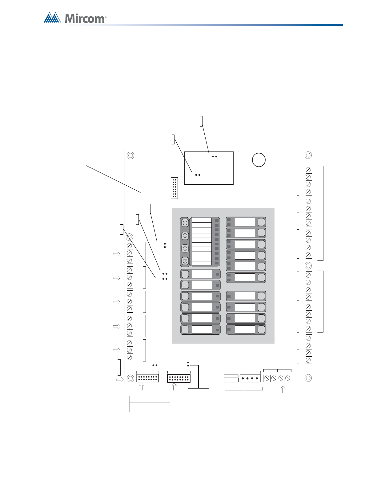
Figure 1 FR-320 Panel
All FR-320 Panels have the following features:
• Six Zone Pre-Action/Deluge and Agent Release Control Panel with LED display (red or
white door, black b ox.
• six Class B (Style B) initiating circuits, and four Class B (Style Y) output circuits
• Output circuits 1 & 2 are Class B (Style B) indicating circuits that can be converted to
Class A (Style Z) using an OCAC-302 Output Class A Converter adder module.
• Output circuits 3 & 4 are Class B (Style B) only releasing circuits.
• Each output circuit can draw 1.7A current, 5A tot al. A si x zone ICAC-306 Input Class A
Converter adder module may be used for Class A (Style D) wiring of Initiating circuits.
• The FR-320 contains Common Alarm, Common Supervisory & Common Trouble
Relays, auxiliary alarm relay (disconnectable), an RS-485 Interface for Remote
Annunciators and a Resettable Four Wire Smoke Detector Power Supply.
• Two batteries are required.
Additionally:
• FR-320-DW/R panels contain a dialer.
• FR-320 uses a BBX-1024DS or BBX-1024DSR enclosure.
Page 17
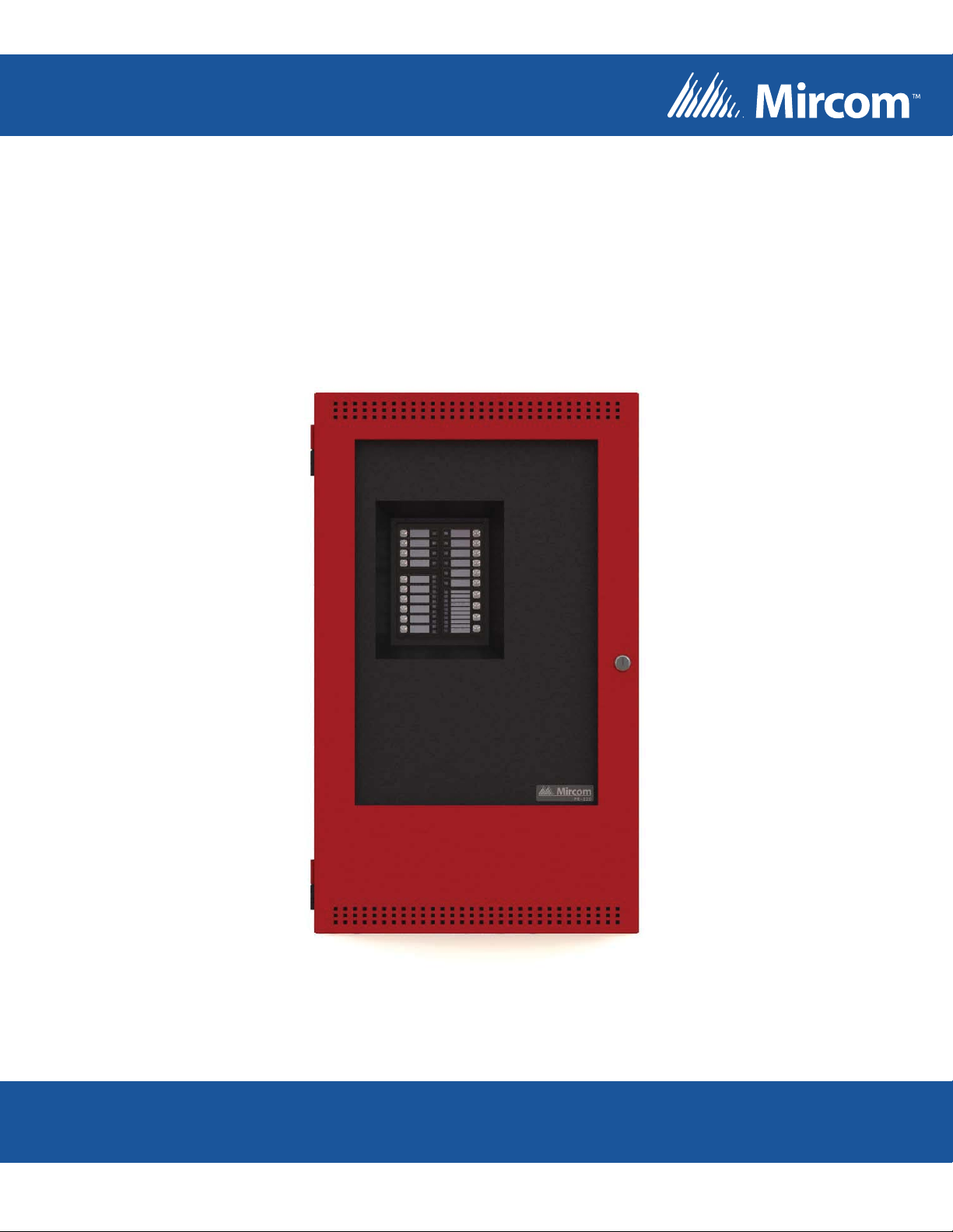
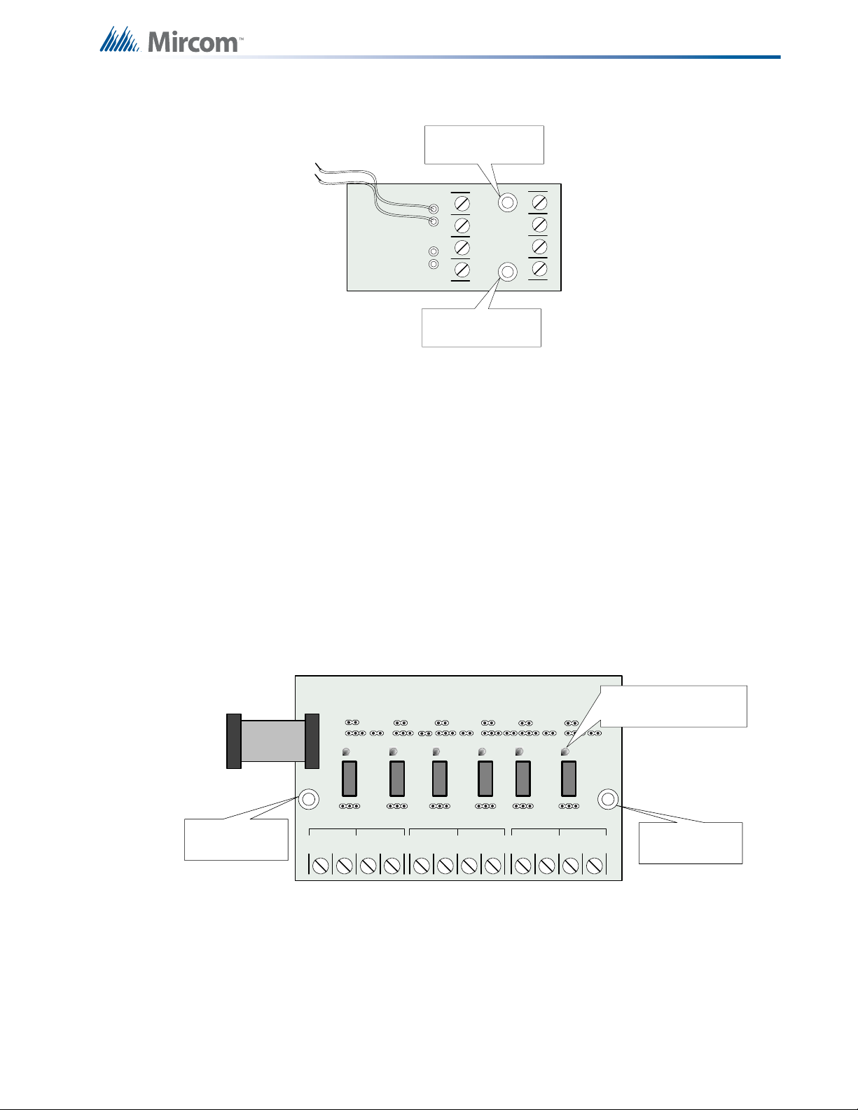
4.2 Relay Modules: Six Relays
NO/NC C
RELAY 1
NO/NC C
RELAY 2
NO/NC
C
RELAY 3
NO/NC C
RELAY 4CRELAY 5
NO/NC C
RELAY 6
NO/NC
POLARITY
REVERSAL
ALARM
POLARITY
REVERSAL
SUPV
CITY
TIE
+ | - + | - + | -
JW4
P1 P2
REMOTE RELAY
Advanced Life Safety Sol utions
FR-320 SERIES
BLK RED
BLK REDBLK REDBLK REDBLK REDBLK RED
- DET1 OUT+- DET2 OUT+- DET3 OUT+- DET4 OUT+- DET5 OUT+- DET6 OUT+
- DET1 RET+- DET2 RET+- DET3 RET+- DET4 RET+- DET5 RET+- DET6 RET+
Model Description
RM-306 Six-relay adder module
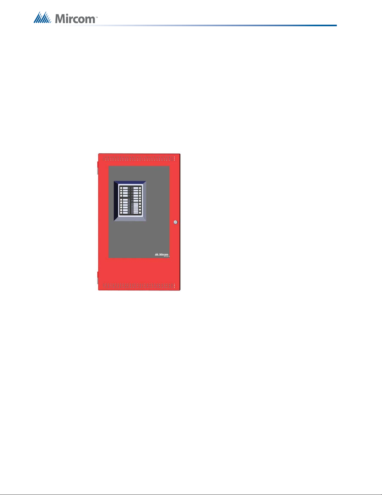
4.3 Polarity Reversal/City Tie
Model Description
PR-300 Polarity Reversal and/or City Tie Module
System Components
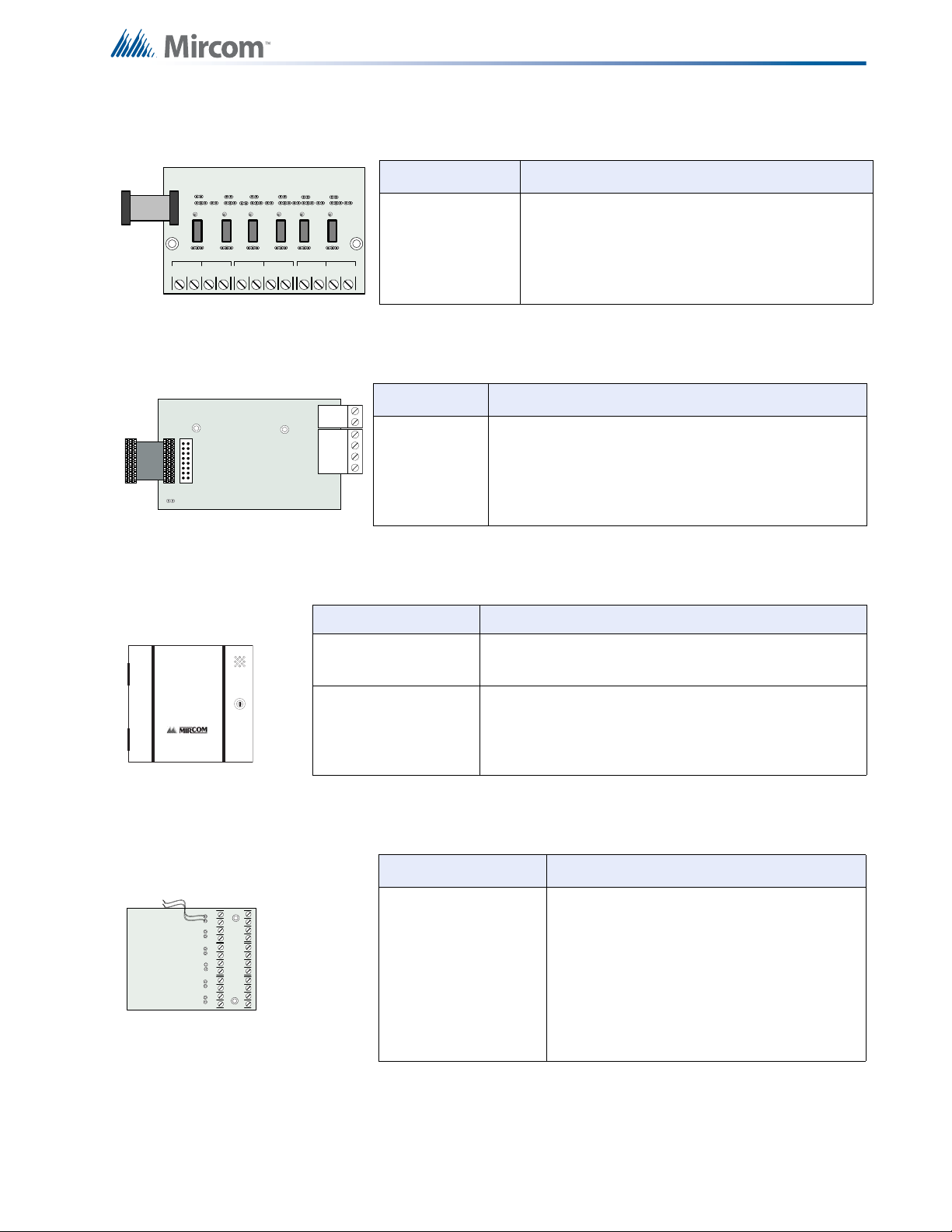
4.4 Smart Relay Module
Model Description
SRM-312W Smart Relay Module (12 relays) with white enclosure
SRM-312R Smart Relay Module (12 relays) with red enclosure
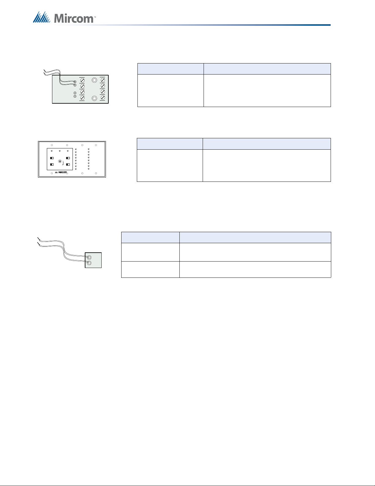
4.5 Input Class A Converter: Six Circuits
Model Description
Input Class A converter Module (six
ICAC-306
circuits). This module has built-in active
EOL resistors.
17
Page 18
4.6 Output Class A Converter: Two Circuits
- SIG1 OUT+- SIG2 OUT+
- SIG1 RET+- SIG 2 RET+
BLK RED
BLK RED
A.C.ONCOMMON
TROUBLE
SIGNAL
SILEBCE
BUZZER
SILENCE
SIGNAL
SILENCE
LAMP
TEST
SYSTEM
RESET
SWITCH
ENABLE
FIRE ALARM
ANNUNCIATOR
BLACK
RED
Model Description
System Components
OCAC-302
4.7 RAM-216 Ancillary Annunciator
Model Description
RAM-216 16 Zone ancillary annunciator
4.8 Active end-of-line
The ELRX-300R(W) are power-saving End-of-Line resistors that eliminate the need for an
additional battery cabinet or larger batteries in order to meet the 60 hour standby requirement.
Model Description
ELRX-300 Active end-of-line resistor without plate
Output Class A converter module (two
circuits)
ELRX-300R Active end-of-line resistor with end-of-line red plate
4.9 Additional System Accessories
RAM-208 Eight Zone Remote Annunciator (ULC and ULI Approved)
RTI-1 Remote Trouble Indicator (ULC and ULI Approved)
RAM-1016/TZ Remote Annunciator (ULC and ULI Approved)
RAM-1016TZDS Remote Annunciator (ULC and ULI Approved)
MP-300 EOL resistor plate, 3.9KΩ (ULC and ULI Approved)
MP-300R EOL resistor plate, red (ULC and ULI Approved)
BC-160 External Battery Cabinet (ULC and ULI Approved)
MP-1500R/W Current Limiter (ULC and ULI Approved)
MP-320R/W Solenoid EOL Module (ULC and ULI Approved)
18
Page 19
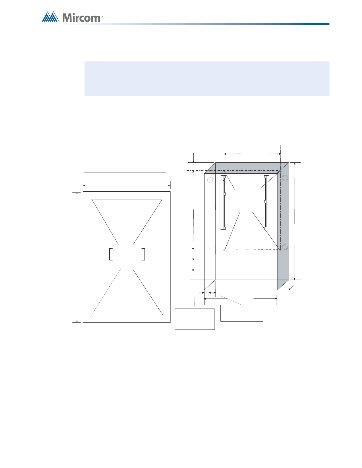
5.0 Mechanical Inst allation
i
17"
22.5"
Adhere trim ring to
wall surfac e around
the FR-320 bac kbox.
PLACE FR-320 TRIM RI NG OVER BACKBOX
14.5"
4
.
5
"
11"
20.0"
1.5"
5.425"
14.5"
3.5"
1"
3.5" is the maximum depth
for semi -flus h mounting
using the fl ush trim ri ng
1" is the mini mum depth
above the wal l requi red
for semi -flush mounting
using the fl ush trim ri ng
4 Mounting
Holes for
Surf ace
Mounting
Note: Installation, use and maintenance should be in accord a nc e with the
manufacturer’s documents and the National Electrical Code, ANSI/NFPA 70, and
the National Fire Alarm Code ANSI/NFPA 72.
5.1 Installing the Enclosure
Install the FR-320 Series panel enclosure as shown below. Mount enclosure surface mount
using the four mounting holes with the provided screws.
Figure 2 Box dimensions, semi-flush mounting and trim ring
Remove the door (also disconnect the gr ound str ap), the de ad front an d se mi-flush mo unt th e
backbox into the wall. Peel the adhesive cover from the trim ring and stick to the wall surface
around the backbox, after wall is finished.
19
Page 20
Mechanical Installation
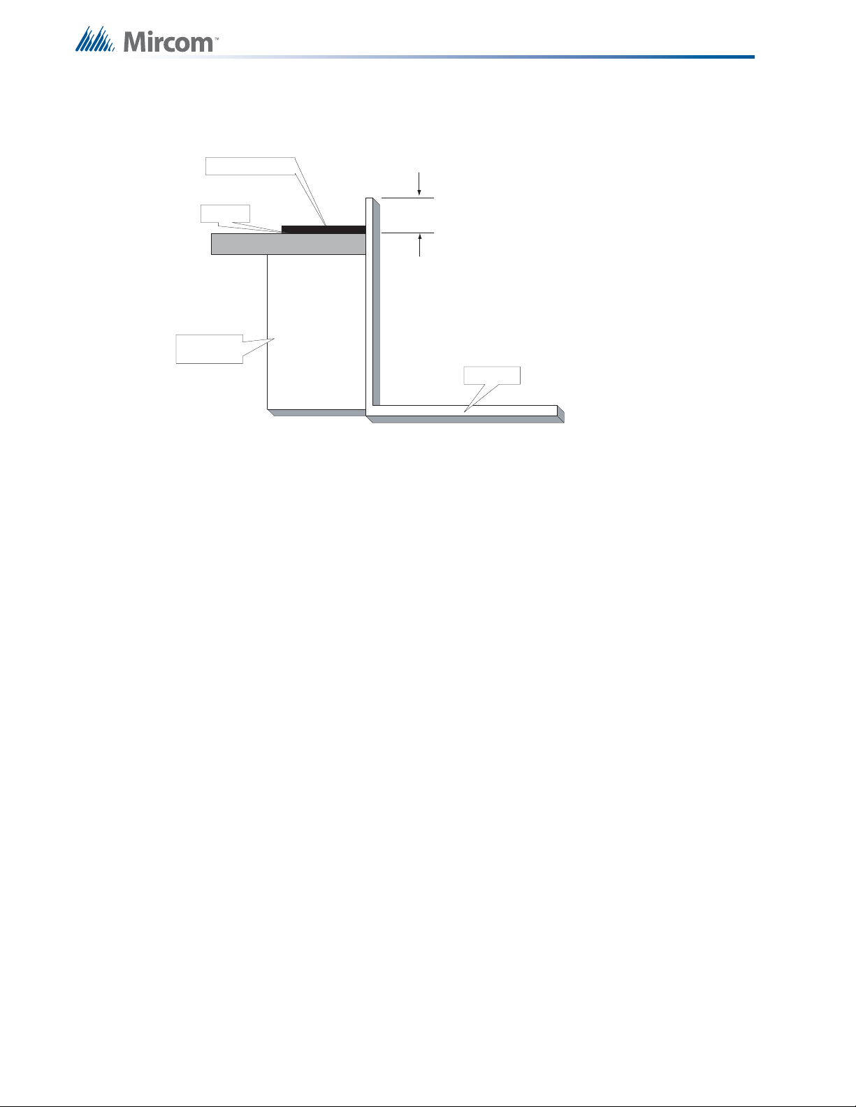
TRIM RING
MIN 1”
WALL
WOOD OR
METAL STUD
BACKBOX
Figure 3 shows a cross-section of the semi-flush mounted backbox and the trim ring. Make
sure to allow a minimum depth of 1” above the wall surface for proper door opening.
Figure 3 Flush Trim Detail
5.2 BBX-1024DS and BBX-1024DSR Mechanical Installation
The BBX-1024DS and BBX-1024DSR are suitable for flush or surface mounting, and have a
built-in trim ring.
Dimensions of Enclosure (minus built in trim ring) 14 1/2” x 4 1/4” x 26”
Distance between horizontal mounting screws 12”
Distance between vertical mounting screws 23 1/2”
Complete Dimensions of Enclosures 16 3/4” x 5 1/2” x 28”
20
Page 21
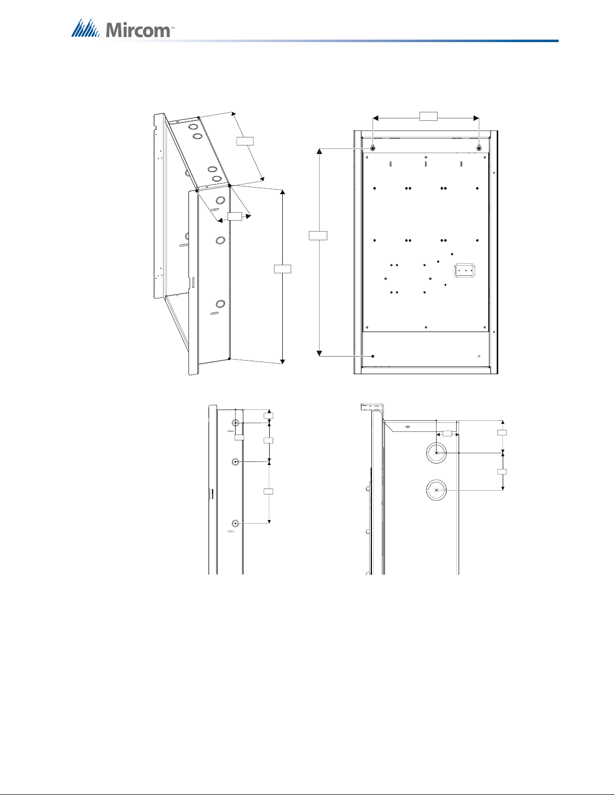
26.0 "
14.5 "
4.2 "
External Dimensions
23.5 "
1.3 "
1.7 "
2.0 "
Top View
2.1 "
1.3 "
6.0 "
9.5 "
Side View
Mechanical Installation
Mounting Dimensions
12.0 "
Figure 4 BBX-1024DS and BBX-1024DSR Installation Instructions and Dimensions
21
Page 22
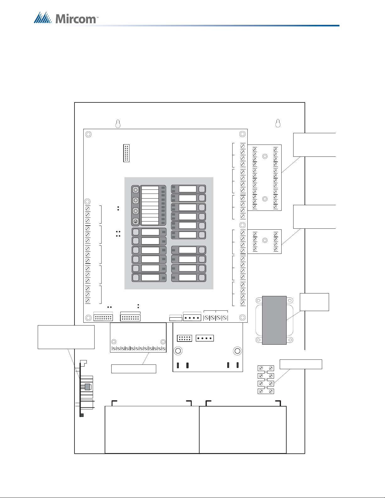
5.3 Installing the Adder Modules
The FR-320 Series panel comes pre-assembled with all components and boards except for
adder modules. Module installation locations are shown below. Refer to Figure 6 on the next
page for Jumper or DIP Switch settings and see 7.8 Wiring Tables and Information on page 35
for wiring specifications.
DET 1DET 2DET 3DET 4DET 5DET 6
-+-+-+-+-+-+
Mechanical Installation
CLASS-A con verter
board for detection
circuits ICAC-306 (6
circuits )
Reverse pola rity and city
tie module PR-300.
Mounted on hex spacer
with two screws provided
JW4
RS-4 85AUX. RELAYAL ARM RE LAY
S-+NC NOCNC NOCNC NOCNC NOC
JW7
JW5
JW6
RELAY
SUPERVISO RY
RELAY
TROU BL E
JW1
TO PR-30 0 MO DULE
Relay Module RM-306
X
M
?
JW2
TO RM-306 RELAY MOD ULE
AC ON
COMMON ALARM
COMMON SUPV
COMMON TROUBLE
BATTERY TROUBLE
REMOTE TROUBLE
GROUND FAULT
CPU FAIL
ABORT
RELEASED
SYSTEM
RESET
SIGNAL
SILENCE
AUXILIARY
DISCONNECT
LAMP
TEST
ALM/SUP/TBL/
BLDG AUDIBLE SIL
PRE
RELEASE
P6
(ZONE 1)
(ZONE 2)
(ZONE 3)
(ZONE 4)
POWER SUPPLY
SIGNAL
P6 P5
BAT TERY
+
P3
IAC1
(ZONE 1)
IAC2
(ZONE 2)
IAC3
(ZONE 3)
IAC4
(ZONE 4)
IAC5
(ZONE 5)
IAC6
(ZONE 1)
NAC1
NAC2
RAC1
RAC2
P4
POWER
-
RTI PORT
UNFLTD SPLY
COM- COM+TRB TRL
SEC TX
P1
SIG 1SIG 2SIG 3SIG 4
AUX
4-WIRE SPLY
-+-+-+-+-+-+
P2
CLASS-A con verter
board for indicating
circuits OC AC-302
(2 circuits)
Transformer
AC wiring terminal
22
BATTERY BATTERY
Figure 5 Installation of Adder Modules
Page 23
6.0 Cable and Jumper Connections for
Main Board, Core Board and Adder
Modules
6.1 Main Pre-Action/Deluge and Agent Release Control Board
JW4 -Factory Use Only
Always Short
JW5- Factory Use Only
Always Open
JW4
Main Board
JW6-Normally Open
RS-485 for
annunciators
Auxiliary Relay
Alarm Re lay
Supervisory
Relay
Trouble Relay
JW1 - ON- when
PR-300 not connected
Connect to PR-300
JW4 -Normally Short
5JW -Normally Open
Connect to
RM306 Relay
module
JW4
RS-4 85AUX. RELAYAL ARM RE LAY
S-+NC NOCNC NOCNC NOCNC NOC
JW7
JW5
JW6
RELAY
SUPERVISO RY
RELAY
TRO UB LE
JW1
TO PR-300 MODULE
P3 P4
TO RM-306 RELAY MODULE
Core Board
JW5
For front panel programming use CFG-300
configuration tool not UL-864 or ULC-S527
listed. Please refer to Document LT-922 for
details
AC ON
X
COMMON ALARM
COMMON SUPV
COMMON TROUBLE
M
BATTERY TROUBLE
REMOTE TROUBLE
?
GROUND FAULT
CPU FAIL
ABORT
RELEASE
SYSTEM
RESET
SIGNAL
SILENCE
AUXILIARY
DISCONNECT
LAMP
TEST
ALM/SUP/TBL/
BLDG AUDIBLE SIL
PRE
RELEASE
JW2
JW2 - ON- when
RM-306 not connected
control interface, including
AC power and battery supplies.
IAC1
(ZONE 1)
IAC2
(ZONE 2)
IAC3
(ZONE 3)
IAC4
(ZONE 4)
IAC5
(ZONE 5)
IAC6
(ZONE 1)
NAC1
(ZONE 1)
NAC2
(ZONE 2)
RAC1
(ZONE 3)
RAC2
(ZONE 4)
SIGNAL
POWER
Power supply and
UNFLTD SPLY
RTI PORT
COM- COM+TRB TRL
Unfiltered 24 V
supply
DET 1DET 2DET 3DET 4DET 5DET 6
-+-+-+-+-+-+
Initiating zones 1 to 6
SIG 1SIG 2SIG 3SIG 4
-+-+-+-+-+-+
AUX
4-WIRE SPLY
Indicating/Releasing zones 1 to 4
Figure 6 Main Control Board cable connector and jumper settings
23
Page 24

Cable and Jumper Connections for Main Board, Core Board and Adder Modules
BLK RED
BLK REDBLK R E DBL K RE DBLK REDBLK RED
- DET1 OU T+- DET2 OUT+- DET3 OUT +- DET4 OUT+- DET5 OUT+- D ET6 OUT+
- DET1 RET+- DET2 RET+- DE T 3 RE T +- DET4 RET+- DET5 RET+- DET6 RET+
mounting hole for
#6-32 scr ews
All these pins comes with
red a nd black w i res w hi ch
are connected to the
detection circuit on the
main fire al arm boa rd . R e d
is p o s itive and black is
negati ve
ICAC-306
mounting ho l e for
#6-32 screws
6.1.1 Connectors and Jumpers on the Main Fire Alarm Board
JW1
Remove this jumper if PR-300 is connected.
P4 Cable from connector P1 of the RM-306 Relay Adder Module connects here.
Otherwise not used.
JW2
Remove this jumper if an RM-306 Relay Adder Module is used.
JW4 Shorted if there is no external unit on RS485. This jumper works as ‘end of line’
jumper. If one or more units are connected on RS485, only short on the last
connected unit. JW4 on all other units should be left open.
JW5 Normally open. To reset the password, place jumper here and power down the
panel (both AC power and batteries). Then power up the panel again, the
password is restored to the default after system startup. Once the system has
reset, REMOVE the jumper from the pins at JW5.
JW6 Normally open to BLOCK configuration via modem, PC with a UIMA converter
module or a CFG-300 Configuration Tool. Place jumper here to ALLOW any type
of configuration.
6.1.2 Connectors and Jumpers on the Core Board
JW4
JW5
Factory Use Only. Always Short.
Factory Use Only. Always Open.
6.2 ICAC-306 Input Class-A Converter Adder Module
Figure 7 ICAC-306 Input Class-A Converter Adder Module
There are no jumpers or cables to set on this module, just wiring from the converter (wires are
fixed here) to the Main Fire Alarm Board.
Initiating circuits must be wired from the ICAC-306 module to the Main Fire Alarm board. For
example, Initiating circuit 1 positive (red) and negative (black) wires are connected to the
positive and negative terminals (respectively) of Initiating circuit 1 on the Main Fire Alarm
Board. From the ICAC-306 converter Initiating circuits are wired out to the devices from the
positive and negative terminals marked DET OUT and the circuit return wires are brought back
to the converter module to positive and negative terminals marked DET RET.
24
Page 25
Cable and Jumper Connections for Main Board, Core Board and Adder Modules
- SIG1 OUT+- SIG2 OUT+
- SIG1 RET+- SIG2 RET+
BLK RED
BLK RED
mounting hol e for
#6-32 screws
OCAC-302
mounting hol e for
#6-32 screws
NO/NC C
RELAY 1
NO/ NC C
RELAY 2
NO/NC C
RELAY 3
NO/NC C
RELAY 4CRELAY 5
NO/NC C
RELAY 6
NO/NC
mounting hol e
for #6-32 screws
mounting hol e
for #6-32 scr ews
INDIVIDUAL GREEN
RELAY S T AT U S LED s
Connect to P6 on the
main fire alarm board
6
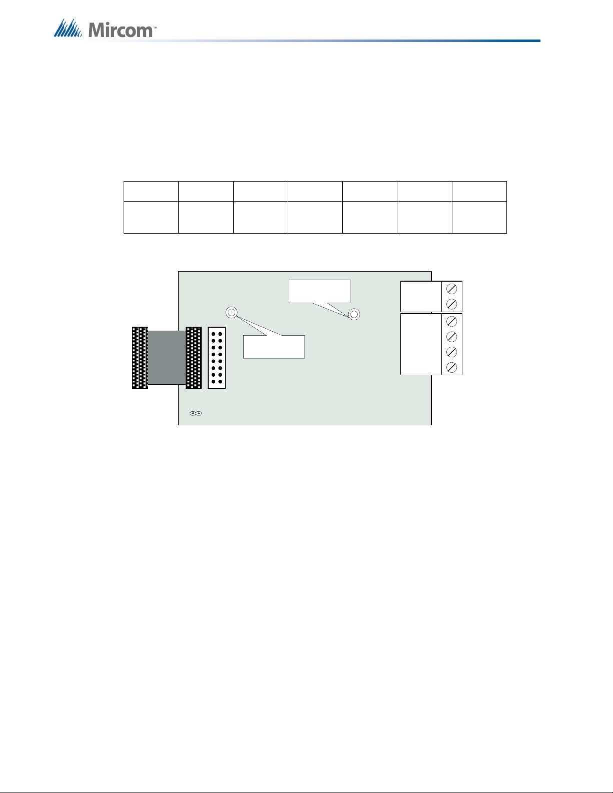
6.3 OCAC-302 Output Class-A Converter Adder Module
Figure 8 OCAC-302 Output Class-A Converter Adder Module
Indicating circuits must be wired from the OCAC-302 to the main Fire Alarm board. For
example indicating circuit 1 positive (red wire) and negative (black wire) is wired from the
Class A converter module to the positive and negative terminals of Indicating circuit 1 on the
Main Fire Alarm board.
The actual indicating zone is wired from the SIGNAL OUT positive and negative to the
signaling devices and then wired back to the SIGNAL RET positive and negative.
6.4 RM-306 Relay Adder Module
Cable from P1 of the RM-306 is connected to P4 on the Main Fire Alarm Board. The jumpers
located above each relay on the RM-306 are used to configure the relays. The jumpers
located below the relays are used to select either normally open contacts or normally closed
contacts.
Figure 9 RM-306 six relay adder module
25
Page 26
6.4.1 RM-306 Jumpers
POLARITY
REVERSAL
ALARM
POLARITY
REVERSAL
SUPV
CITY
TIE
+ | - + | - + | -
JW4
P1 P2
Mounting hole for
#6-32 screws
Mounting hole for
#6-32 screws
P1 Cable from RM-306 Relay Adder Module connects to P4 on Main Fire Alarm
Board.
6.4.2 RM-306 Correlations
The correlation of the relays are fixed and is as follows:
Relay1 Relay2 Relay3 Relay4 Relay5 Relay6
Cable and Jumper Connections for Main Board, Core Board and Adder Modules
Active
State
Hazard 1
Alert
Hazard 1
Alarm
Hazard 1
Release
Hazard 2
Alert
Hazard 2
Alarm
Hazard 2
Release
6.5 Polarity Reversal and City Tie Module (Model PR-300)
Figure 10 Polarity reversal and city tie module
The following hardware configuration must be performed before installing the PR-300.
6.5.1 PR-300 jumper settings
26
P1
P2 & JW4
The Alarm Transmit sign al to the PR-300 can be programmed to turn OFF when signal silence
is active. This allows the City Tie Box to be manually reset. On subsequent alarms the
silenceable signals will resound and the City Tie Box will be retriggered. See 8. Alarm Xmit-
Sil. on page 55 for more information.
The Trouble Transmit signal to the PR-300 can be programmed to delay AC power fail for 0, 1
or 3 hours if this is the only system trouble. See 9. Pwr Fail Tmr on page 55 for more
information.
Cable connects to P3 on the Main Board
Not used. Jumper JW4 remains on board.
Page 27
7.0 Field Wiring
!
+
-
STYLE B
WIRING
STYLE B
WIRING
INITIATING
CIRCUIT #1
INITIATING
CIRCUIT #2
INITIATING
CIRCUIT - 1
ALARM ZONE
INITIATING
CIRCUIT - 2
SUPERVISORY
ZONE
ION SMOKE
DETECTOR
PHOTO SMOKE
DETECTOR
HEAT
DETECTOR
PULL STATION
3.9K 1/2 WATT ELR
SUPERVISORY
FIRE ALARM MAIN BOARD
+
-
DET 1DET 2
NOTE: ACTIVE END OF LINE
RESISTORS MAY BE USED, BUT
THEY MUST BE USED ON ALL THE
INITIATING CIRCUITS.
Table 1 Settings permitted in CAN/ULCS527
NOTICE TO USERS, INSTALLERS, AUTHORITIES HAVING JURISDICTION, AND OTHER INVOLVED PARTIES
This product incorporates field-programmable software. In order for the product to comply with the
requirements in CAN/ULCS527, Standard for Control Units for Fire Alarm Systems, certain programming
features or options must be limited to specific values or not used at all as indicated below.
Program feature or
option
Permitted in CAN/
ULCS527? (Y/N)
System Reset and
Signal Silence on RAM-
N
208/216
7.1 Main Board Field Wiring
Wire devices to the terminals as shown in the figures that follow. Refer to 7.8 Wiring Tables
and Information on page 35 for wire gauges and 17.0 Appendix E: Specifications on page 101
for specifications.
Caution: Do not exceed power supply ratings.
Possible settings\methods
JW4 (Orange Wire) Intact =
Buzzer silence & Lamp Test
local function only. System
Reset & Signal Silence are
disabled.
Cut Jumper (Orange Wire) to
have all remote functions
operate.
Settings permitted in
CAN/ULCS527
Leave JW4 intact on
RAM-208/216
7.1.1 Initiating Circuit Wiring
Wiring diagrams for the initiating circuits are shown below. The panel supports Style B wiring
for the initiating circuits and Style D wiring for the indicating circuits. The initiating circuits are
supervised by a 3.9KΩ EOL resistor or an active EOL module.
Figure 11 Initiating circuit – Class B or Style B Wiring
27
Page 28
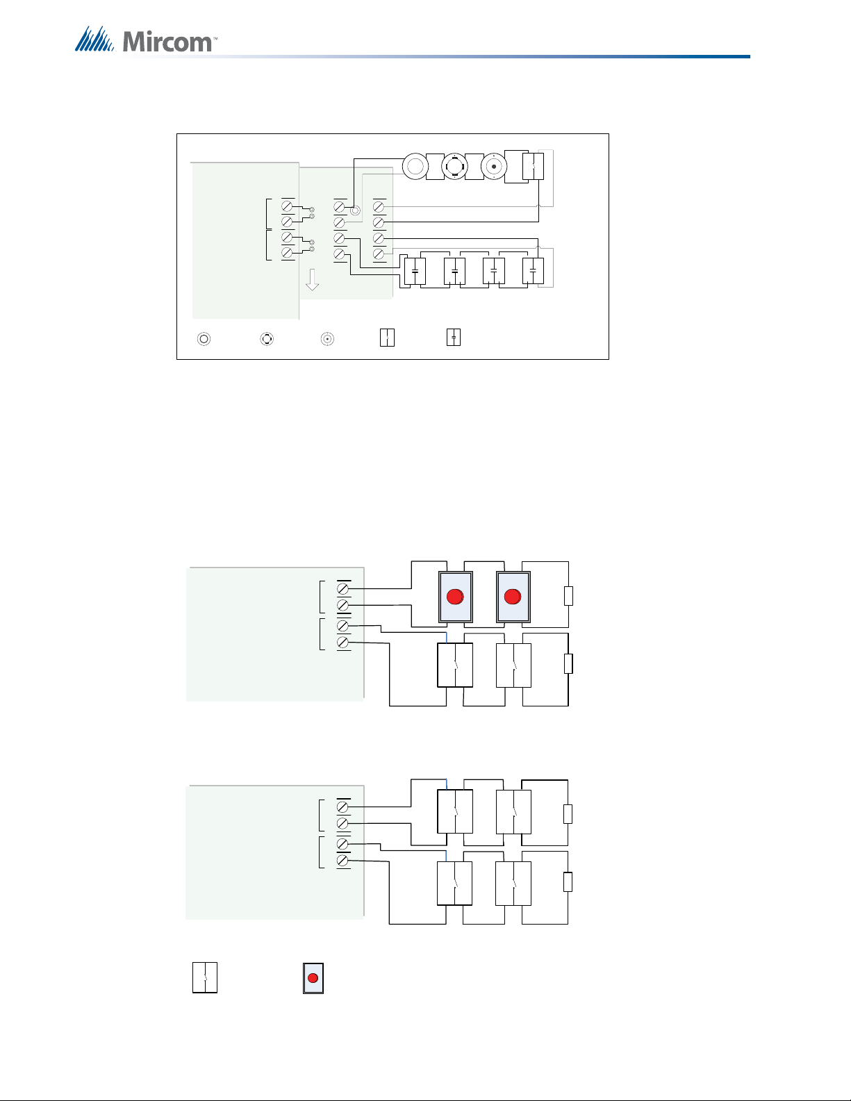
Figure 12 Initiating circuit– Class A or Style D Wiring
+
-
STYLE D
WIRING
STYLE D
WIRING
INITIATING
CIRCUIT #1
INITIATING
CIRCUIT #2
INITIATING
CIRCUIT - 1
ALARM
ZONE
INITIATING
CIRCUIT - 2
SUPERVISORY
ZONE
ION SMOKE
DETECTOR
PHOTO
SMOKE
DETECTOR
HEAT
DETECTOR
PULL STAT I O N
SUPERVISORY
4 MORE INITIATIN G
CIRCUITS NOT SHOWN
DCAC-306 CLASS A
CONVERTER MODULE
FIRE ALARM MAIN BOARD
BLK RED
BLK RED
- DET1
OUT+
- DET2
OUT+
- DET1 RET+- DET2 RET+
+
-
DET 1DET 2
ICAC-306
FIRE ALARM MAIN BOARD
+
-
+
-
DET 5DET 6
INITIATING
CIRCUIT #5
INITIATING
CIRCUIT #6
3.9K 1/2 WAT T EL R
OR ELRX-300/R
3.9K 1/2 WAT T EL R
OR ELRX-300/R
MANUAL RELEASE
SWIT CH
Use MS-403 ,404
USE ONLY NO
CONTACT
ABORT SWIT CH
CONNECT A UL /ULC LISTED ABORT STATION ACCEPTABLE TO
THE AHJ, COMPLYING WITH THE FOLLOWING SPECIFICATIONS:
MAXI MUM IMPEDANCE = 1.4K O HMS
RATED CURRENT = 45mA
RATED VOLTAGE= 24 V
Manual Release switches on separate circuits
Abort and Manual Release switches on separate circuits
FIRE ALARM MAIN BOARD
+
-
+
-
DET 5DET 6
INITIATING
CIRCUIT #5
INITIATING
CIRCUIT #6
3.9K 1/2 WAT T EL R
OR ELRX-300/R
3.9K 1/2 WAT T EL R
OR ELRX-300/R
7.2 Abort and Manual Release Switch Wiring
Field Wiring
Wiring for the abort and manual release switches is shown in Figure 13 and Figure 14. The
Abort and Manual release switches must be on different circuits. DET5 is used for the Abort
switch and DET6 is used for the manual release switch.
28
Figure 13 Abort and Manual Release Switch Class B or Style B Wiring
Page 29
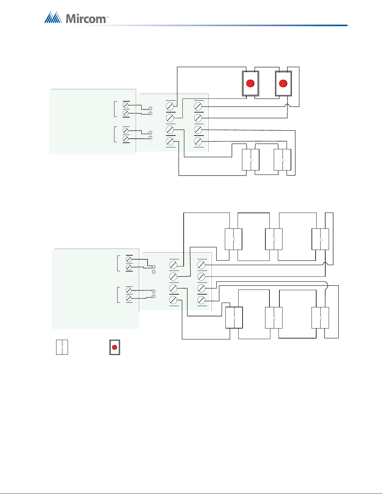
FIRE ALARM MAIN BOARD
+
-
+
-
DET 5DET 6
INITIATING
CIRCUIT #5
INITIATING
CIRCUIT #6
FIRE ALARM MAIN BOARD
+
-
+
-
DET 5
DET 6
INITIATING
CIRCUIT #5
INITIATING
CIRCUIT #6
MANUAL RELEASE
SWIT CH
USE MS -403 ,404
USE ONLY NO
CONTACT
ABORT SWITCH
CONNECT A UL /ULC LISTED ABORT STATION
ACCEPTABLE TO THE AHJ, COMPLYING WITH THE
FOLLOWING SPECIFICATIO NS:
MAXI MUM IMPEDANCE = 1.4K O HMS
RATED CURRENT = 45mA
RATED VOLTAGE= 24V
Abort and Manual Release switches on separate circuits
.
BLK RED
BL K R ED
-DET5 OUT+-DET6 OUT+
-DET5 RET+-DET6 RET+
BLK RED
BL K R ED
-DET5 OUT+-DET6 OUT+
- DET5 RET+-DET6 RET+
ICAC-306
CLASS A
CONVERTER
MODULE
ICAC-306
CLASS A
CONVERTER
MODULE
Manual Release switches on separate circuits
Field Wiring
Figure 14 Abort and Manual Release Switch Class A or Style D Wiring
29
Page 30
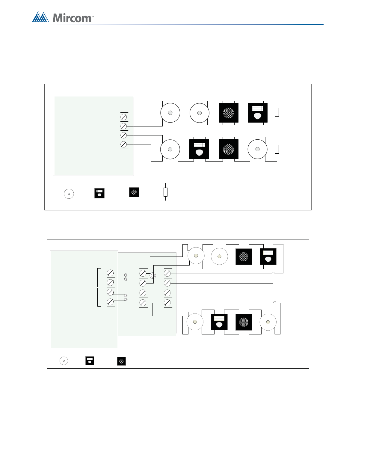
7.3 Indicating Circuit Wiring
-SIG 1 +
STYLE Y
WIRING
STYLE Y
WIRING
INDICATING
CIRCUIT - 1
INDICATING
CIRCUIT - 2
BELL STROBE 3.9K 1/2 WATT ELR
INDICATING
CIRCUIT #1
INDICATING
CIRCUIT #2
HORN
FR-320 Panel
-SIG 2 +
BELL STROBE HORN
+
-
STYLE Y
WIRING
STYLE Y
WIRING
INDICATING
CIRCUIT #1
INDICATING
CIRCUIT #2
INDICATING
CIRCUIT 1
INDICATING
CIRCUIT 2
OCAC-302 CLASS A
CONVERTER MODUL E
FR-320 Panel
BL K R ED
BL K R ED
-SIG1 OUT+-SIG2 OUT+
-SIG1 RET+-SIG2 RET+
+
-
SIG 1SI G 2
The FR-320 Series Fire Alarm supports Class B or Style Y and Class A Style Z wiring for its
indicating circuits. Each circuit is supervised by a 3.9KΩ EOL resistor or active EOL module.
Each indicating circuit provides up to 1.7 A, 5 A maximum total if no auxiliaries are used.
Field Wiring
Figure 15 Indicating circuit – Class B or Style Y wiring
30
Figure 16 Indicating circuit –Class A or Style Z wiring
Page 31

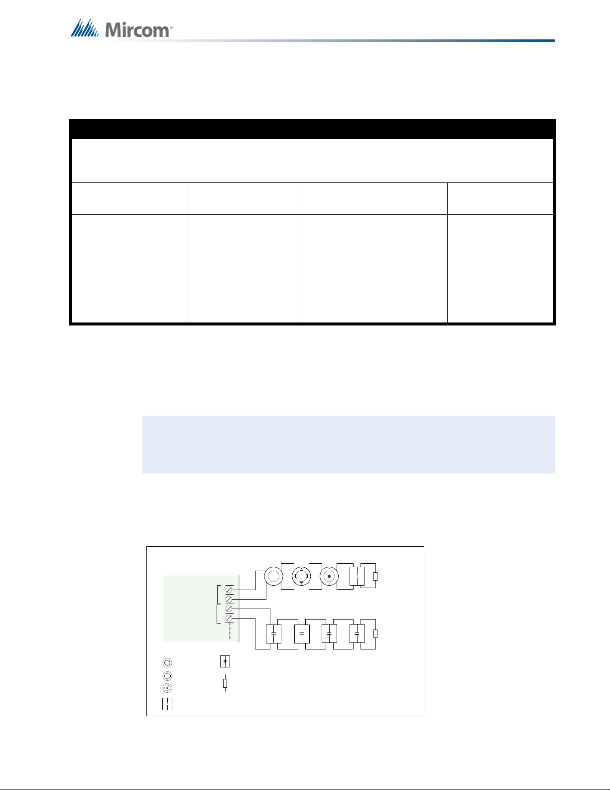
7.3.1 Releasing Circuit Wiring
FIRE ALARM MAIN BOARD
+
-
+
-
SIG 3SIG 4
Re leasing
circuit #1
Re leasing
circuit #2
Solenoid EOL
module
MP-320R/ W
Solenoid EOL
module
MP-320R/ W
Solenoid Coil (See
the list ing for the
approved solenoids)
WARNING: EOL has to be close nipple
connected to the solenoid coil.
TIPTIP RINGRING
premise telephone
IF permitted
TIPTIP RINGRING
LINE-1
LINE-2
1
23
4
8
5
76
Public switch
Telephone company
wiring
TIP
RING
TIP
RING
RJ31X
GREY
BROWN
RED
GREEN
COCO RESRES
Line 2 is Wired as shown for Line 1
FIRE ALARM MAIN
BOARD
Wiring for the releasing circuit is shown in F i gur e 17 below. SIG3 and SIG4 output circuits are
reserved for the releasing circuits. Solenoid EOL module (MP-320R/W) is used to supervise
the solenoid coil. If the solenoid is already fitted with the directional diode then only the 3.9KΩ
EOL resistor is used. The supervisory current passes through the solenoid coil thus confirming
the integrity of the solenoid coil for open coil. The wiring is supervised for the open and short
conditions.
Field Wiring
7.4 Dialer Wiring (US only)
Figure 17 Releasing Circuit Wiring
If you have an FR-320D, there is a dialer on board and terminals marked Line 1 and Line 2
must be wired as shown in Figure 18 below.
Figure 18 Dialer Wiring
31
Page 32

7.5 Four-Wire Smoke Detector Wiring
POWER
DETECTION
++
++
--
--
1
4
2
3
5
6
TO INITIATING
CIRCUIT
RESETTABLE 4-WIRE SMOKE
DETECTOR POWER SUPPLY
22VDC, 200mA
MAX. CURRENT - 300mA
MAX. RIPPLE VOL. 5mV
(POWER LIMITED)
4-WIRE DETECTION DEVICE
END OF LINE RELAY
LISTED S3403
MODEL A77-716B
MANUFACTURED BY
SYSTEM SENSOR
+
-
4-WIRE
SUPPLY
3.9K 1/2 WATT ELR
LEGEND
NOTES
ALL POWER LIMITED CIRCUITS
MUST USE TYPE FPL, FPLR,
OR FPLP POWER LIMITED
CABLE
FIRE ALARM M AIN BOARD
C
C
NO/NC
NO/NC
C
NO/NC
ALL RELAY CONTACTS
28V DC, 1 AMP
RESISTIVE LOAD
RM-306 6 RELAY ADDER MODULE
NORMALLY OPEN OR
NORMALLY CLOSED
CONNECTION IS
SELECTED BY JUMPER
ON RELAY BOARD.
NOTE: ALL RELAYS ARE POWER LIMIT ED
CIRCUITS AND MUST USE TYPE FPL, FPLR or
FPLP POWER LIMITED CABLE.
NORMALLY OPEN
CONNECTION
NORMALLY CLOSE
CONNECTION
RELAY
CIRCUIT #1
RELAY
CIRCUIT #2
RELAY
CIRCUIT #6
Field Wiring
7.6 Relay Adder Module Wiring
Figure 19 Four-wire smoke detector wiring
Wire relays on the relay adder module RM-306 as shown in Figure 20.
32
Figure 20 Relay per zone (RM-306) Terminal connection
Page 33

7.7 Polarity Reversal and City Tie Module (PR-300) Wiring
1
1
2
2
S
S
CITY TIE LOCAL ENERGY
RATED - 24VDC FILTERED
TRIP COIL - 14 Ohms, 250mA,
5mV RIPPLE
POLARITY REVERSAL ALARM
24VDC OPEN
12VDC AT 3.5mA
8mA MAX. SHORT
POLARITY REVERSAL SUPV.
24VDC OPEN
12VDC AT 3.5mA
8mA MAX. SHORT
PROTECTOR
1
1
2
2
S
S
1
1
2
2
S
S
PROCTECTOR
1
1
2
2
S
S
USE A SHORTING WIRE
WHEN THE CITY TIE IS
NOT USED
+
+
+
-
-
-
+
+
+
-
-
-
CONFIRMS TO NEMA STANDARD
SB3-1969 INTENDED FOR
CONNECTION TO POLARITY
REVERSAL CIRCUIT OF A REMOTE
STATION RECEIVING UNIT HAVING
COMPATIBLE RATINGS
DIN RAIL CONNECTION
TO EARTH GROUND
DIN RAIL CONNECTION
TO EARTH GROUND
POWER LIMITED
POWER LIMITED
POWER LIMITED
PR-300
PROCTECTEDPROCTECTED
UNPROCTECTEDUNPROCTECTED
POWER LIMITED CABLE TYPE
FPL, FPLR or FPLP MUST BE
USED FROM PR-300 TO
PROTECTORS.
Wire PR-300 Polarity Reversal and City Tie Mod ule (if used) as shown in Figure 21 below . See
17.0 Appendix E: Specifications on page 101 for module specifications. Power Limited cable
type FPL, FPLR or FPLP must be used.
For USA installation, the installer must use Atlantic Scientific (Tel: 407-725-8000), Model
#24544 Protective Device, or similar UL-Listed QVRG secondary protector, as shown.
For use in Canada, the Protective Device is not required but still recommended.
Field Wiring
Figure 21 Polarity reversal and city tie module terminal connection
33
Page 34

Field Wiring
!
BATTERY BATTERY
red
green
blk
yellow
P3
BAT TERY
P4
+
-
P1
P2
P6 P5
POWER SUPPLY
RAC2
(ZONE 4)
SPARE
RAC1
(ZONE 3)
P6
Deluge Panel Control Board
Power Supply Control Board
red
red
10A
slow blow
++
red
blk
NOTE: TO PREVENT SPARKING, CONNECT BATTERIES AFTER THE
SYSTEM MAIN A.C. POWER IS TURNED ON
240 VAC 50Hz
120 VAC 60Hz
N
GND
ALM/SUP/TBL/
BLDG AUDIBLE SIL
7.7.1 Power Supply Connection
The power supply is part of the Main Chassis. The ratings are:
Table 2 Power Supply Ratings
Type Rating
Electrical Input rating 120 VAC 60Hz 1.7A /240 VAC 50 Hz 0.85 A, 10A slow blow fuse on
secondary of transformer
Power supply total current
Battery fuse on Main module
Wire the power supply as shown below in Figure 22 using the proper wire gauge.
Caution: Do not exceed power supply ratings.
6.5A AC maximum @ secondary of transformer
10A, slow blow micro fuse
Figure 22 Power Supply Connection
34
Page 35

7.8 Wiring Tables and Information
i
i
Table 3 Initiating Circuit Wiring Distances
WIRE GAUGE MAXIMUM WIRING RUN TO LAST DEVICE
AWG FEET METERS
22 2990 910
20 4760 1450
18 7560 2300
16 12000 3600
14 19000 5800
12 30400 9200
Notes: For Class A the maximum wiring run to the last device is divided by two.
Maximum loop resistance should not exceed 100 ohms.
Maximum capacitance of 0.5uF total on each initiatin g circuit.
Field Wiring
Table 4 Indicating Circuit Wiring Distances
TOTAL
SIGNAL
LOAD
Amperes ftmftmftmftm Ohms
0.06 2350 716 3750 1143 6000 1829 9500 2895 30
0.12 1180 360 1850 567 3000 915 4720 1438 15
0.30 470 143 750 229 1200 366 1900 579 6
0.60 235 71 375 114 600 183 950 289 3
0.90 156 47 250 76 400 122 630 192 2
1.20 118 36 185 56 300 91 470 143 1.5
1.50 94 29 150 46 240 73 380 115 1.2
1.70 78 24 125 38 200 61 315 96 1.0
MAXIMUM WIRING RUN TO LAST DEVICE (ELR) MAX. LOOP
18AWG 16AWG 14AWG 12AWG
Notes: For Class A wiring the resistance in ohms is multiplied by two.
Maximum voltage drop should not exceed 1.8 volts.
RESISTANCE
7.9 Four-Wire Smoke Power (regulated)
Four-wire smoke power is provided for four-wire smoke detectors. This filtered supply is
supervised therefore a short will disconnect the power and the common trouble is active. The
power is reconnected after the 'RESET' key is pressed. See 17.0 Appendix E:
Specifications on page 101 for supply rating.
35
Page 36

7.10 Supervised Auxiliary Power (regulated)
Supervised auxiliary power is used to power the remote annunciators and smart relay
modules. This filtered circuit is supervised therefore a short will disconnect the power and the
common trouble is active. The power is reconnected after the 'RESET' key is pressed. See
17.0 Appendix E: Specifications on page 101 for supply rating.
7.11 Unfiltered Supply (full wave rectified)
This regulated supply is not supervised. If there is a short on this circuit, the auxiliary power
does not recover automatically when the short is removed. This power supply must be
disconnected, then reconnected and the panel reset to re-establish the auxiliary power supply.
See 17.0 Appendix E: Specifications on page 101 for supply rating.
Field Wiring
36
Page 37

8.0 System Checkout
i
8.1 Before turning the power “ON”
To prevent sparking, do not connect the batteries. Connect the batteries after powering the
system from the main AC supply.
1. C hec k that all modu les ar e installed in the proper location with the proper connections.
2. Check all field (external) wiring for opens, shorts, and ground.
3. Check that all interconnection cables are secure, and that all connectors are plugged in
properly.
4. Check all jumpers and switches for proper setting.
5. Check the AC power wiring for proper connection.
6. Check that the chassis is connected to EARTH GROUND (cold water pipe).
7. Make sure to close the front cover plate before powering the system from main AC
supply.
The best way to check out a panel first is to not connect any field wiring. Power up the panel
with an end of line. The panel should be free of trouble. Then connect one circuit at one time.
If a trouble occurs, correct the fault then continue the field wiring.
8.2 Power-up procedure
After completing the System Checkout procedures outlined above,
1. Power up the panel. The "AC ON" green LED and the “Common Trouble” LED shou ld
illuminate, and the buzzer should sound. Press the “System Reset” button. Since the
batteries are not connected, the trouble buzzer should sound intermittently and the
common trouble LED should flash.
2. Connect the batteries while observing correct polarity: the red wire is positive (+) and
black wire is negative (-). All indicators should be OFF except for normal power "AC ON"
green LED and green LED I4 (below the TROUBLE relay at left bottom of board).
Note: Green LED I4 is illuminated when the system is normal. This LED indicates that
the trouble relay is in normal standby condition.
3. Configure the Fire Alarm Control Panel as described in the Configuration section.
37
Page 38

8.3 Troubleshooting
Table 5 Troubleshooting
Symptoms Possible Cause
To correct the fault, check for open wiring on that particular circuit loop or if the Circuit
Circuit Trouble
Disconnect Button is active. Notes: (1) Bypassing a detection circuit or signal circuit will
cause a system trouble (off-normal status); (2) Bypassing a releasing circuit will cause a
supervisory signal.
System Checkout
Remote
Trouble
Ground Fault
Battery
Trouble
Common
Trouble
Remote Trouble will be indicated on the main panel display for any failure reported by,
or failure to communicate with a remote annunciator or other remote device.
This panel has a common ground fault detector. To correct the fault, check for any
external wiring touching the chassis or other Earth Ground connection.
Check for the presence of batteries and their conditions. Low voltage (below 20.4V) will
cause a battery trouble. If battery trouble condition persists, replace batteries as soon
as possible.
If only a common trouble is indicated on the main panel and none of the above
confirming trouble indicators are on, check the following for possible fault:
• Check for any missing interconnection wiring.
• Check for any Module missing that was part of the Configuration.
• Check for improperly secured cabling.
38
Page 39

9.0 Indicators, Controls and Operations
SYSTEM
RESET
AC ON
X
M
?
GROUND FAULT
CPU FAIL
ABORT
RELEASED
COMMON ALARM
COMMON SUPV
REMOTE TROUBLE
COMMON TROUBLE
BATTERY TROUBLE
SIGNAL
SILENCE
AUXILIARY
DISCONNECT
LAMP
TEST
PRE
RELEASE
RAC2
(ZONE 4)
RAC1
(ZONE 3)
NAC2
(ZONE 2)
NAC1
(ZONE 1)
IAC6
(ZONE 1)
IAC5
(ZONE 5)
IAC4
(ZONE 4)
IAC3
(ZONE 3)
IAC2
(ZONE 2)
IAC1
(ZONE 1)
ALM/SUP/TBL/
BLDG AUDIBLE SIL
i
Refer to Figure 23 below for LED Indicator and Control Button locations.
Figure 23 LED indicators and control buttons
The Main Display Panel on the Main Pre-Action/Deluge and Agent Release Control Board
consists of:
LED Indicators may be amber, red, or green, and may illuminate continuously (steady), or at
one of two flash rates.
• 16 common LED Indicators (left portion of display)
• Ten Common Buttons (left half portion of display)
• Up to six Initiating Circuit Alarm LEDs and six Initiating Circuit Trouble LED Indicators
• Four Indicating/Releasing Circuit LEDs (labeled NAC for Notifying Appliance Circuit or
RAC for Releasing Appliance Circuit)
• Up to ten disconnect buttons (six for initiating circuits & four for indicating/releasing
circuits)
• Fast Flash (Supervisory)- 120 flashes per minute, 50% duty cycle
• Trouble Flash (Trouble) - 20 flashes per minute, 50% duty cycle
Note: Each display is supplied with laser printer printable paper labels for sliding into
the plastic label template on the panel. For the Main Display, the paper label is
Mircom# NP-2056. This includes English and French versions.
39
Page 40

9.1 Common LED Indicators
9.1.1 AC On
The AC ON led is on steady green while the main AC power is within acceptable levels. It is
turned off when the level falls below the power-fail threshold.
9.1.2 Common Alarm
The common alarm led is illuminated steady red as a result of any active alarm present in the
system.
9.1.3 Common Trouble
The common trouble led in illuminated steady amber as a result of a trouble condition being
detected on the system.
9.1.4 Battery Trouble
Flashes amber at a slow rate, when the battery vo ltage is lower than th e specified threshold or
the battery is off line. Flashes amber at a fast rate when there is a trouble on the battery
charger circuit.
Indicators, Controls and Operations
9.1.5 Remote Trouble
Flashes amber at a slow rate as a result of any remote trouble condition.
9.1.6 Ground Fault
Flashes amber at a slow rate when there is a ground fault detected in the system.
9.1.7 CPU Fail
Flashes amber at a slow rate when the CPU is not working properly.
9.1.8 Abort
Illuminate steady amber when the abort circuit is active.
9.1.9 Released
Illuminate steady red when the releasing circuit(s) is active.
9.1.10 System Reset
Turn on steady amber during the system reset process.
9.1.1 1 Signal Silence
Flashes amber at a slow rate when the signal circuits are silenced.
9.1.12 Auxiliary Disconnect
Flashes amber at a slow rate when the auxiliary disconnect function is active.
9.1.13 Lamp Test
Illuminate amber steady when the lamp test button is pressed.
40
Page 41

Indicators, Controls and Operations
M
M
?
9.1.14 ALM/SUP/TBL/BLDG AUDIBLE SIL (Buzzer Silence)
Flashes amber at a slow rate when the buzzer is silenced.
9.1.15 Pre Release
Flashes red at a fast rate, when the release timer is started turns off when the release timer
expires or the system is reset.
9.2 Menu Buttons
To use the menu buttons you will need to install the CFG-300 configuration tool. See 10.1
Using the CFG-300 Tool on page 48 31 for details.
Menu Button
Menu
Button
Info
?
Button
Enter
Button
X
Cancel
Button
Pressing and entering the passcode will allow you to enter the command menu.
When the system is off-normal, press to display extra information of the event.
Pressing this button to select a menu option or to confir m a me n u op er a tion .
To return to previous menu in the configuration or command mode.
9.3 Switches and Common Indicators
The FR-320 Series panel is a six-zone panel with four output circuits. The circuits are
arranged in the following configuration:
Zone 1 Input circuit
Zone 2 Input circuit
Zone 3 Input circuit
Zone 4 Input circuit
Zone 5 Manual Release switches or Abort switches or individual switch
Zone 6 Manual Release switches or individual switch
Out 1 NAC1
Out 2 NAC2
Out 3 Releasing circuit 1
Out 4 Releasing circuit 2 or NAC3 in some applications
9.3.1 Zone 1 to Zone 4
• Alarm LED (red) turns on steady when an alarm is detected
• Supervisory LED (amber)turns on steady when the circuit is active
• Trouble LED (amber)turns on at slow flash rate when in trouble or bypassed
9.3.2 Zone 5 and Zone 6
• Alarm LED & Trouble LEDThe zone type and LED behavior varies upon the
configuration. Steady when turned on.
41
Page 42

9.3.3 Out1 and Out2 (NAC circuits)
• Trouble LED (amber)turns on at slow flash rate when in trouble or bypassed
9.3.4 Out3 and Out4 (Releasing circuits)
• Trouble LED (amber)turns on steady when the circuit is bypassed
turns on at slow flash rate when in trouble
9.3.5 Input Circuits Bypass Switch
These bypass switches are used to bypass the input circuit. Bypass is a toggle switch which
will bypass and un-bypass in a sequence whenever the switch is pressed. When the input
circuit is bypassed a trouble is generated and the system will not respond to any trouble or
alarm on the bypassed input circuit. If the bypassed input circuit is active and the Bypass
Switch is pressed for un-bypassing, the Alarm LED will flash at the fast rate for 10 seconds.
During these 10 seconds, pressing the Bypass Switch can bypass the active input circuit
again. After 10 seconds, the bypassed alarm will be processed.
9.3.6 Output Circuits Bypass Switch
The output circuit bypass switches bypasses the NAC circuit and the releasing circuit. The
switch is a toggle switch and pressing it again, will un-bypasses the output circuit the tr ouble
LED turns off.
Indicators, Controls and Operations
9.4 Common Controls
9.4.1 System Reset Button
The System Reset button resets the Fire Alarm C ontrol Panel and all Circuits. In particular, the
system reset button
• Resets all Latching Trouble Conditions
• Resets all Initiating and Releasing Circuits
• Resets 4-Wire Smoke Supply
• Turns off all Indicating Circuits
• Turns off Signal Silence Indicator
• Stops and resets all Timers
• Processes inputs as new events
• Does not affect Aux Disconnect
9.4.2 Signal Silence Button
Activation of the Signal Silence button when the panel is in alarm turns on the Signal Silence
indicator and deactivates any Silenceable Indicating Circuits. Non-Silenceable Circuits are
unaffected. Signals will re-sound upon any subsequent alarm. Subsequent operation of signal
silence resounds all Silenceable signals. This button does not function during any configured
Signal Silence Inhibit Timer period.
9.4.3 Auxiliary Disconnect Button
Activating the Auxiliary Disconnect button activates the Auxiliary Disconnect function. The
Auxiliary Alarm Relay is always disconnected with this button. The Common Alarm Relay, the
Common Supervisory relay and all correlated alarm relays may be disconnected as selected
through configuration. Activating the Auxiliary Disconnect button also causes the Common
Trouble LED to illuminate steady, the common trouble relay to send a trouble message and
the trouble buzzer to flash at the trouble flash rate. Pressing the Auxiliary Disconnect button
42
Page 43

Indicators, Controls and Operations
again de-activates this function and the system will go back to normal.
9.4.4 Lamp Test Button
Activation of the Lamp Test button causes all front panel Indicators to steadily illuminate and
turns the buzzer ON steady. If Lamp T est is active for more th an 10 seconds, Common T rouble
is activated.
9.4.5 ALM/SUP/TBL/BLDG AUDIBLE SIL Button (Buzzer Silence)
Activation of the ALM/SUP/TBL/BLDG AUDIBLE SIL button while the buzzer is sounding
silences the buzzer. The buzzer will resound if there is a subsequent event. Pressing the
button when the buzzer is not sounding has no effect.
9.5 Circuit (zone) disconnect buttons
Circuit (Zone) Disconnect pushbuttons are provided for all initiating indicating, and releasing
circuits on the Fire Alarm Control Panel. These pushbuttons are located beside their
respective indicating LED.
Pressing a Circuit Disconnect pushbutton by passes the associated circuit and turns on its
Trouble Indicator, activating Common Trouble. Pressing a releasing circuit disconnect
pushbutton bypasses the associated releasing circuit and turns on it s LED, activating common
supervisory. While a Circuit is disconnected, all changes in status (alarms and troubles) on
that circuit are ignored. The panel does not activate disconnected indicating circuits. Circuit
Disconnect pushbuttons are toggle switches; therefore, pressing an activated switch a second
time will un-bypass (reconnect) the circuit.
Disconnecting an active Latching Initiating Circuit (including Alarms, Water flow Alarm,
Sprinkler Alarm, Gen eral Alarm, and Latching Supervisory) does not affect its status until the
panel is reset. Disconnecting an active Non-Latching Initiating Circuit (including Non-Latching
Supervisory and Trouble-Only) causes them to behave as if the alarm situation has
disappeared. Disconnecting an active indicating circuit immediately deactivates the circuit.
When an Initiating Circuit Disconnect pushbutton is returned to the normal st ate (by pressing it
again in order to un-bypass the circuit), the panel checks the state of the circuit. If the circuit is
active, the Status Indicator flashes for 10 seconds at the Fast Rate without processing the
input. If the Circuit is not re-bypassed by then, it will be processed as a new input.
43
Page 44

9.6 Common Relays
i
i
Table 6 Relay Types
Relay Type Single Hazard Dual Hazard
Trouble Relay Trouble Trouble
Supervisory Relay Supervisory Supervisory
Alarm Relay Alarm Hazard1 (Alarm)
Aux Alarm Relay Alarm (Silence-able) Hazard2 (Alarm)
Note: Some troubles are latching once they are detected they remain active until
system reset. In this case the common trouble indicator will also remain active
until system reset. The common trouble is not bypassed by the auxiliary
disconnect function.
Indicators, Controls and Operations
9.7 Circuit Types
9.7.1 Initiating (Detection) Circuit Types
9.7.2 Non-Verified Alarm
A Non-Verified alarm is a “normal” type of alarm that can have pull stations, smoke detectors,
or heat detectors attached to it. Activation of any of these devices will immediately result in an
alarm condition in the Fire Alarm Control Panel. An Alarm cond itio n ca us es the as so ciat ed
Circuit Status LED and the Common Alarm LED to illuminate red.
9.7.3 Water Flow Alarm (Water flow Sensors)
Water Flow Alarms are identical to normal Non-Verified Alarms except that any indicating
circuits programmed to these circuits (all are by default) are Non-Silenceable. Also, if Water
Flow Retard Operation is enabled, these circuits are sampled every one second. If ten
samples are active within any 15-second interval, the Water flow Alarm is confirmed and
processed. An alarm condition causes the associated Circuit Status LED and the Common
Alarm LED to illuminate red.
Note: Do not use Retard Operation with any external retard ing device; maximum r etard
may not exceed 120 seconds.
9.7.4 Non-Latching Supervisory (For Supervisory Circuits)
Activation on these circuits will cause the Circuit Status LED and the amber Common
Supervisory LED to illuminate. The buzzer will sound at fast rate. If the circuit activation is
removed, the Supervisory condition will clear (as long as there are no other Supervisory
conditions in the system) and the Circuit Status LED will turn off.
44
Page 45

9.7.5 Latching Supervisory (For Supervisory Devices)
Activation on these circuits will cause the Circuit Status LED and the amber Common
Supervisory LED to illuminate. The buzzer will sound at fast rate. If the circuit activation is
removed, the Supervisory condition will NOT clear.
9.7.6 Abort Switch
When the hazard area is in alarm (pre-discharge) state and the r elease timer is running, the
activation of the corresponding Abort Switch will pause the releasing timer. The release
process is held while the Abort Switch is pressed. Releasing the Abort Switch will resume the
releasing timer and the corresponding hazard area goes into Alarm (pre-discharge) state
again. The value of the release timer after Abort Switch is released depends on the type of
Abort Delay in the configuration. When the release timer expires, the corr espo nd ing rele asing
circuit is activated. When the panel is in normal condition, activation of the Abort Switch will
cause a trouble signal and the corresponding zone amber LED turns on at slow flash rate.
9.7.7 Manual Release Switch
Activation of the Manual Release Switch of a hazard area will activate the corresponding
releasing circuit. If the corresponding Manual Release Delay is non-zero, the releasing circuit
will be activate after the Manual Release Delay expires.
Indicators, Controls and Operations
9.7.8 Indicating (Signal) Circuits Types
9.7.9 Silenceable Signal
The Silenceable Signal circuit is used for audible devices such as bells and piezo mini-horns
that may be silenced either manually or automatically.
9.7.10 Non-Silenceable Signal
The Non-Silenceable Signal Circuit is used for audible devices such as bells and piezo minihorns that may not be silenced either manually or automatically. While sounding, these
devices follow the evacuation code pattern that is configured by the user. For more information
on evacuation codes, refer to 9.8 Evacuation codes on page 46.
9.7.11 Silenceable Strobe
Silenceable strobes will be silenced when the “signal silence” key is pressed.
9.7.12 Non-Silenceable Strobes
Non-Silenceable Strobes will not be silenced when the “signal silence” key is pressed.
45
Page 46

9.8 Evacuation codes
CONTINUOUS
TEMPORAL CODE
0.5s
1.5s 1.5s
0.5s
0.25s 0.25s
0.5s
0.5s
1.5s
20 BPM
60 BPM
120 BPM
Continuous On 100% of the time
Temporal Code 3 of 0.5 second on, 0.5 second off then, 1.5 second pause
20 BPM 1.5 seconds on, 1.5 seconds off
60 BPM 0.5 second on, 0.5 second off
120 BPM 0.25 second on, 0.25 second off
Indicators, Controls and Operations
46
Figure 24 Evacuation and Alert Codes
Page 47

10.0 Configuration
Table 7 Settings permitted in CAN/ULCS527
NOTICE TO USERS, INSTALLERS, AUTHORITIES HAVING JURISDICTION, AND OTHER INVOLVED PARTIES
This product incorporates field-programmable software. In order for the product to comply with the
requirements in CAN/ULCS527, Standard for Control Units for Fire Alarm Systems, certain programming
features or options must be limited to specific values or not used at all as indicated below.
Program feature or
option
Temporal pattern in
conjunction with manual
alarm evacuation
control
Auto signal silence
timer
Abort and manual
release on same circuit
(unsupervised)
Table 8 Settings permitted in UL864
NOTICE TO USERS, INSTALLERS, AUTHORITIES HAVING JURISDICTION, AND OTHER INVOLVED PARTIES
This product incorporates field-programmable software. In order for the product to comply with the
requirements in UL864, Standard for Control Units and Accessories for Fire Alarm Systems, certain
programming features or options must be limited to specific values or not used at all as indicated below.
Program feature or
option
Permitted in CAN/
ULCS527? (Y/N)
Y
Y
N
Permitted in UL864?
(Y/N)
Possible settings\methods
Modes 1, 2, 3, 4, 5, 6, 7, 8, 9,
10, 11, 12, 13, 14
Disabled or 5, 10, 20, or 30
minutes
Modes 1, 2, 3, 4, 5, 6, 7, 8, 9,
10, 11, 12, 13, 14
Possible settings\methods
Settings permitted in
CAN/ULCS527
Modes 9, 11
Disabled
Modes 1, 2, 5, 6, 7, 8,
9, 10, 11, 12, 13, 14
Settings permitted in
UL864
AC power fail delay Y
Abort and manual
release on same circuit
(unsupervised)
Configure the FR-320 Series Panels using the CFG-300 LCD Tool (see further documentation
packaged with CFG-300 for configuration information).
0, 60, 180 minutes 60, 180 minutes
N
Modes 1, 2, 3, 4, 5, 6, 7, 8, 9,
10, 11, 12, 13, 14
Modes 1, 2, 5, 6, 7, 8,
9, 10, 11, 12, 13, 14
47
Page 48

10.1 Using the CFG-300 Tool
SYSTEM
RESET
AC ON
X
M
?
GROUND FAULT
CPU FAIL
ABORT
RELEASED
COMMON ALARM
COMMON SUPV
REMOTE TROUBLE
COMMON TROUBLE
BATTERY TROUBLE
SIGNAL
SILENCE
AUXILIARY
DISCONNECT
LAMP
TEST
PRE
RELEASE
RAC2
(ZONE 4)
RAC1
(ZONE 3)
NAC2
(ZONE 2)
NAC1
(ZONE 1)
IAC6
(ZONE 1)
IAC5
(ZONE 5)
IAC4
(ZONE 4)
IAC3
(ZONE 3)
IAC2
(ZONE 2)
IAC1
(ZONE 1)
0
QZ
8
TUV
7
PRS
9
WXY
1
2
ABC
3
DEF
4
GHI
5
JKL
6
MNO
This label
removed from
this location
represents t he
alternat e
func t ions of the
corresponding
butt ons in
service mode
*
(left shift)
#
(right shift)
ALM/SUP/TBL/
BLDG AUDIBLE SIL
Configuration
Connect the CFG-300 to the panel, then press (Menu button). The CFG-300 LCD display
M
will display the Main Menu. The function of different buttons on the front panel display is
shown in Figure 25 below.
Figure 25 FR-320 Configuration
10.2 Entering the Passcode
The programming section is passcode protected. The following screen shows the message
that is displayed to enter the passcode. The maximum allowable passcode is ten digits long,
and permits numerical values only. Press (Enter button) after entering the passcode. If
the passcode is correct, it will take you to the main command menu. If the passcode is wrong
the system will ask you to re-enter passcode. The system will be exhausted after three retries
and will then take you back to the Normal message display.
48
Page 49

Configuration
Enter passcode:
_
When the user presses “MENU” and enters the password, they should enter the password of
the level intended. If the user is in a lower level of access, attempts to operate func tio ns
requiring a higher level of access will be refused. The three levels of access are defined in
Table 9.
Tab l e 9 Acce s s Le ve ls
Access Level Description
Level 0 - Command The default password is for this level “1111” without quotes. In this le vel the
user can only perform regular testing and operation.
Level 1 - Configuration The default password is for this level “2222” without quotes. User can
change configuration and have access to command level.
Level 2 - Factory Currently not used.
10.3 How to Use the Keypad to Program the FR-320
1. Press (Menu button). You will be prompted to enter your password.
2. Enter your password, then press (Enter button) to continue.
3. Select a Command Menu option by pressing . The corresponding submenu will
display.
4. U se the up and do wn arr ow buttons to scroll through the submenu.
5. Press to select a submenu option.
6. Use the left or right arrow buttons to select/unselect an option (selected = “X
up and down arrows to scroll through the different menu options. When entering
numerical data, use the up and down arrows to increase or decrease the number.
7. Once you have made the correct selection, press to confirm the change. The
display will return to the submenu screen.
8. Press (Cancel button) to return to the previous menu.
M
X
”). Use the
49
Page 50

10.4 Command Menu
i
Access level Required
Configuration
Configuration
Configuration
Command
Command
Command
Configuration
Command
Command
The main command menu is shown in Figure 26. The first line of the LCD will always show
“-Command Menu-“, and the second line scrolls through dif ferent selections. Use the “UP” and
“DOWN” keys to scroll through the menu, and press the key to make a selection. To exit
Configuration
from the main command menu, select the “Exit” menu option and then press either the or
key.
Note: Command Menu Item 1 and 6 can only be accessed if jumper JW6 is placed on
the main board.
X
Figure 26 Command Menu
Pressing “LAMP TEST” at any time will show the information about the system and the
software version. The first line shows the panel mode number, pre-programmed mode and the
information if the panel has a dialer or not. The second line shows the software version
number. The version of the software is read as Major.Minor.Revision.
50
Page 51

10.5 1. Panel Config (Command-Menu)
i
Choose a mode:
1
The following is a detailed description of the FR-320 config u ra tio n me nu .
Note: Refer to 10.3 How to Use the Keypad to Program the FR-320 on page 49 for
detailed instructions on making menu selections.
-Panel Config-
1. Choose a mode
2. Hazard C onfig
3. Panel Features
4. Default Config
10.5.1 Command Menu-->Panel Config-->Choose a mode
Command Menu-->Panel Config--> Choose a mode
1. Choose a mode
1-->Default
Configuration
Use this function to choose a
pre-programmed panel
configuration.
Selections range from modes 1
to 14. Refer to 12.0 Pre-
Programmed Modes on page 69
for details on mode
configurations.
Note: changing the fixed
configuration of the panel will
cause all configuration data
set to default for that
particular mode.
51
Page 52

10.5.2 Command Menu-->Panel Config-->Hazard Config
i
Release timer(sec):
60
Abort Delay Type:
[X] Standard UL
-Hazard P aram .-
1. Release timer
2. Abort Delay
3. Manual Rls
Delay
4. Soak timer
Note: Refer to 10.3 How to Use the Keypad to Program the FR-320 on page 49 for
detailed instructions on making menu selections.
Configuration
Command Menu-->Panel Config--> Hazard Config
1. Release Timer
Command Menu-->Panel Config--> Hazard Config
2. Abort Delay
60->Default
Available options:
0,5,10,15,20,25,30,35,40,
45,50,55,60 seconds
[X] Standard UL->Default
[ ] IRI
[ ] NYC
[ ] Local Juris.
Use this function to set the
programmable timer that delays the
activation of the releasing application
circuits.
This timer starts immediately after
receiving a confirming alarm (crosszoned hazard area) or a single alarm
(non-cross-zoned hazard area).
When the timer expires, the releasing
circuit activates.
Value: 0 to 60 seconds in five-second
increments.
Use this function to set how the Abort
Switch operates with the Release
Timer.
Note that if the Release Timer is set
to zero, the Abort Switch does not
operate.
In Standard UL mode, the release
timer will stop and hold when th e
Abort Switch is pressed. When the
switch is released, the Release T imer
restarts from whichever is gr eater: the
remaining time on the timer or 10
seconds.
In IRI mode, the switch works in the
same way as it does in Standard UL
mode, except that the switch will
function only if it is pressed and held
before the second alarm comes in.
In NYC mode, pressing the Abort
Switch will reset to the Release Timer
and add 90 seconds to the configured
timer duration. After the Abort Switch
is released, the Release Timer will
restart.
In Local Juris. (Local Jurisdiction
Delay), pressing the Abort Switch will
reset the Release Timer back to its
configured value. After the switch is
released, the Release Timer will
restart.
52
Page 53

Command Menu-->Panel Config-->
i
Hazard Config
3. Man. Rls Delay
Man. Rls Delay(sec):
0
0->Default
Available options:
0, 5, 10, 15, 20, 25, 30
seconds
Configuration
Use this function to set the time delay
of activation of corresponding
releasing circuit(s) after activation of
the manual release switch.
Value: 0 to 30 seconds in five-second
increments.
Command Menu-->Panel Config--> Hazard Config
4. Soak timer
Man. Rls Delay(sec):
0
Command Menu-->Panel Config-->Features
-Panel Features-
1. Man. Sig. Sil
2. Wtr/Sprk. Retd
3. Aux Dis Corr
4. Sig-Sil Inh Tm
5. Aux Dis Alm&Sv
6. Auto Sil. Tmr
7. Rem. Annun.
8. Alm. Xmit. Sil.
0->Default (continuous)
The selectable values are
in seconds: 0, 10, 20, 30,
40, 50, 60, 120(2min),
180(3min), 240(4min),
300(5min), 360(6min),
420(7min), 480(8min),
540(9min), 600(10min),
660(11min), 720(12min),
780(13min), 840(14min),
900(15min)
Use this function to set the length of
time for which the releasing circuit is
active. When the soak timer expires,
the control panel automatically shuts
off the activated releasing circuit.
0 seconds means that the soak timer
is disabled and the releasing circuit is
active continuously.
9. Pwr Fail Tmr.
10. Com. Supv. Rly
11. Sig. Sil. Isol.
12. 1st Alarm Code
13. 2nd Alarm Code
14. Supv. Latching
15. Supv on NAC-2
16. Sig -Sil NAC
Note: Refer to 10.3 How to Use the Keypad to Program the FR-320 on page 49 for
detailed instructions on making menu selections.
53
Page 54

Command Menu-->Panel Config-->Features
Man. Sig. Sil.
[X] EN ABLE
Waterflow/Sprk Retd
[X] DISABLE
1. Manual Sig. Silence
[X] ENABLE ->Default
[ ] DISABLE
Configuration
Use this function to enable or
disable the Signal Silence
operation on the panel.
Command Menu-->Panel Config-->Features
2. Wtr/Sprk. Retd
Command Menu-->Panel Config-->Features
3. Aux Dis Corr
Aux Dis. Dis Corr
[X] EN ABLE
Command Menu-->Panel Config-->Features
4. Sig-Sil Inh Tmr
Sig- Si l . Inhi bit Ti mer
[X] DISABLE
Command Menu-->Panel Config-->Features
5. Aux. Dis. Dis Alam&Sv
Aux Dis. Dis Alm&Sv
[X] DISABLE
Command Menu-->Panel Config-->Features
6. Auto Sig-Sil. Tmr
Auto Sig-Sil. Tmr
[X] DISABLE
[ ] ENABLE
[X] DISABLE->Default
[X] ENABLE ->Default
[ ] DISABLE
[X] DISABLE->Default
[ ] 10sec
[ ] 20sec
[ ] 30sec
[ ] 1min
[ ] ENABLE
[X] DISABLE->Default
[X] DISABLE->Default
[ ] 5 Min
[ ] 10 Min
[ ] 20 Min
[ ] 30 Min
By default all the initiating circuits
configured as waterflow or
sprinkler act as non-verified
alarms. If enabled, a retard
operation is performed for initiating
circuits configured as waterflow or
sprinkler.
By default this function will
disconnect the auxiliary alarm
relay when the aux disconnect
button is pressed. If enabled, this
function will disconnect the
auxiliary alarm relay and all
correlated relays when the aux
disconnect button is pressed.
Correlated relays include: RM306 and SRM-312.
Use this function to inhibit the
signal silence switch for a desired
length of time. The time period
should expire before the signals
may be silenced. According to the
Canadian National Building Code ,
this timer should be set to one
minute.
If enabled the Common Alarm and
Common Supervisory relays will
be disconnected when Aux.
Disconnect is pressed. Also, the
PR-300 will not transmit a
supervisory or alarm event.If
disabled, the Aux disconnect
switch has no effect on the
Common Alarm relay, the
Common Supervisory relay, and
the PR-300.
Use this function to set the time
period for which the indicating
circuits will sound before they are
automatically silenced. For
Canadian installations, disable the
Auto Signal Silence Timer.
Command Menu-->Panel Config-->Features
7. Rem. Annun.
No. of Remote Annun.
[X] NONE
54
[X] NONE->Default
[ ] 1
[ ] 2
...
[ ] 6
Use this function to program the
number of remote annunciators.
Any combination of remote
annunciators or smart relays can
be used as long as the number
does not exceed 6. The
annunciators’ addresses should be
linear: without gaps and in
sequence.
Page 55

Command Menu-->Panel Config-->Features
8. Alarm Xmit-Sil.
Alm Xmit- Sil.
[X] DISABLE
Command Menu-->Panel Config-->Features
9. Pwr Fail Tmr
AC Pwr Fail Dly Tmr.
[X] None
[ ] ENABLE
[X] DISABLE->Default
[X] NONE->Default
[ ] 1 HRS
[ ] 3 HRS
Configuration
Use this function to allow the
alarm transmit and auxiliary alarm
relay to reset on the Signal Silence
rather than the Reset switch.
Use this function to delay the
reporting of AC power fail trouble
for a specific time period. If
disabled, the AC power fail will be
reported immediately.
Command Menu-->Panel Config-->Features
10. Com. Supv. Rly
Common Supv. Relay
[X] EN ABLE
Command Menu-->Panel Config-->Features
11. Sig-Sil. Isol.
Sig-Sil. Isol.
[X] DISABLE
Command Menu-->Panel Config-->Features
12.1st Alarm NAC Code
1st Alarm NAC Code
[X] Temporal
Command Menu-->Panel Config-->Features
13. 2nd Alarm NAC Code
2nd Alarm NAC Code
[X] 120 BPM
[X] ENABLE->Default
[ ] DISABLE
[ ] ENABLE
[X] DISABLE->Default
[X] Temporal ->Default
[ ] 20 BPM
[X] 120 BPM->Default
[ ] 60 BPM
[ ] Temporal
If disabled, the common
supervisory relay can be used as a
common alarm relay. It will act the
same way as a common alarm
relay. If enabled, it is used as a
common supervisory relay.
Enable this function only when
suite isolators are used (Canada
only).
Sets the NAC indicating code
when the 1st alarm comes in.
Choose the NAC indicating code
when the 2nd alarm comes in.
Command Menu-->Panel Config-->Features
14.Supv. Latching
S u pe r vi s o r y L a t c hi ng
[X] Non-latching
Command Menu-->Panel Config-->Features
15. Supv on NAC-2
Supv. Alert on NAC-2
[X] DISABLE
[ ] Latching
[X] Non-latching->Default
[ ] ENABLE
[X] DISABLE->Default
Use this function to set the
supervisory circuit as either
latching or non-latching.
NOTE: For ULC operation the
supervisory should be
programmed as latching
Use this function to enable/disable
the supervisory circuit indication
on NAC-2.
55
Page 56

Command Menu-->Panel Config-->Features
Load the default
Settings? Y
i
1. Daylight Save
2. Time Clock
3. Compensation
Daylight Saving
[X] DISABLE
HH:MM WKD YYYY-MM-DD
00:00 MON 2000-01-01
16. Sig-Sil NAC
[X] NAC-1->Default
Silenceable NAC
[X] NAC-2->Default
[X] NAC-1
Command Menu/FR-320 Config/Features/
17. Active EOL
Active EOL
[X] DISABLE->Default
[ ] ENABLE
[X] DISABLE
10.5.3 Command Menu-->Panel Config-->Default Config
Command Menu-->Panel Config--> Default Config
4. Default Config
Y-->Default
Configuration
Use this function to set which NAC
circuits are silenceable or nonsilenceable.
Enable this function if using an
Active EOL. If ICAC-306 is used,
this function should be enabled
since the Class A Converter has
built in Active EOL resistors.
Use this function to reset the panel
to the default configuration of the
chosen programming mode.
10.6 2. Set Time (Command-Menu)
Note: Refer to 10.3 How to Use the Keypad to Program the FR-320 on page 49 for
detailed instructions on making menu selections.
Command Menu/Set time Date
1. Daylight saving time
[X] DISABLE ->Default
[ ] ENABLE
Command Menu/Time Clock
2. Set time and date
Default
00:00 MON 2000-01-01
Use this function to enable daylight savin gs
time.
Use this function to set the time and date.
Use the “LEFT” and “RIGHT” keys to move
the cursor to the desired location in the
display and use the “UP” and “DOWN” keys
to increase or decrease the values. Press
the “ENTER” key to accept the changes and
the “CANCEL” key to ignore the changes.
Note: time is in 24hr format
56
Page 57

Command Menu/Time Clock
HH:MM WKD YYYY-MM-DD
00:00 MON 2000-01-01
Daily Compen. (Sec):
Panel Config Updated
Select Access Level
0
Enter new passcode:
Re-enter new passcode:
invalid passcode
passcode updated
2. Compensation
Configuration
Default: 0 seconds
(no compensation)
When value is entered the following message
will appear
• 3. Set password (Command-Menu)
First choose the level of password to be changed
Compensation values
can range from -15 to
+15 seconds.
Then
Use the up down arrow keys to select daily
compensation value and press ENTER. For
a fast clock adjust negatively. For a slow
clock adjust positively. For example: for a
clock which runs 5 minutes a month (based
on 30 days) fast select -10 seconds.
If the passcode does not match, the following message
appears and the system exit to the main menu
If the passcode is OK the following message appears
and exits to the main menu
The user can change the password only for the current access level as well as any lower
levels.
0 -> Default
Use this function to change the passcode. The minimum number of digits
is 4 and the maximum is 10. Only
numeric digits are allowed.
57
Page 58

10.7 4. View Event Log (Command-Menu)
EVENT
type
EVENT
01 of 09
"INFO" Key
Zone-1
OPEN TRB 01/09
ZONE
Message
NVERI F ALARM Z-01
11:45 THU 2005-3-31
Process
Type
Physical
Zone No.
DATE
TIME
The event log looks the same as the normal event queue. Pressing the “INFO” key has the
same effect that it does in the event queue. The illustration below provides an example of how
the “INFO” key works and shows the CFG-300 LCD Configuration tool display.
There are a maximum of 200 recent events saved in the event log. If the number of events
goes beyond 200, the oldest event is overwritten by the most recent one.
Configuration
10.8 5. Print Event Log
Select the type of log to print. Press the
“ENTER” key. The system will then print
the requested log
Use this function to print the Alarm or General log.
58
Page 59

10.9 6. Clear Event Log (Command-Menu)
i
-Select Log-
1. Alarm Log
2. General Log
3. All Logs
Clear all the
Selected log(s)? Y
Log(s) cleared
i
-Dialer Config-
1. Account Info
2. Telephone line
3. Report Options
4. Time Parameter
5. Enable/Disable
Note: Refer to 10.3 How to Use the Keypad to Program the FR-320 on page 49 for
detailed instructions on making menu selections.
Select the type of log to clear. Press the
“ENTER” key. The system will then
confirm before clearing logs.
Use this function to clear alarm logs, event logs, or both.
Configuration
Press the “ENTER” key to confirm or the
“CANCEL” key to cancel the operation.
10.10 7. Dialer Config (Command-Menu)
Note: Refer to 10.3 How to Use the Keypad to Program the FR-320 on page 49 for
detailed instructions on making menu selections.
The following illustration shows the dialer configuration menu. This menu will show up only if
there is a built-in dialer on the main board. Each item in th is menu is d escribed b elow in d etail.
59
Page 60

Command Menu-->Dialer Config
-Account Info-
1. Account#1 ID
2. Account#1 Tel
3. Accnt#1 Format
4. Account#2 ID
5. Account#2 Tel
6. Accnt#2 Format
Account#1 ID
123 45 6
Account#1 Telnum:
101
ACCOUNT#1 Format:
[X] CONTACT ID
ACCOUNT#2 ID:
654321
10.10.1 Account Info
Configuration
Command Menu/Dialer Config/Account Info
1.Account# 1 Identification
Command Menu/Dialer Config/Account Info
2.Account#1 Telephone Number
Command Menu/Dialer Config/Account Info
3.Account#1 Reporting Format
123456->Default
[101]->Default
[X] CONTACT ID-Default
[ ] SIA 300 Baud
[ ] SIA 110 Baud
Use this function to set the Account ID for
the monitoring station to which the dialer
reports events. The maximum # of digits
allowed is six. For contact ID, only the first
four digits are used; the last two are
truncated.
If you are using contact ID the allowed
digits for the account ID are simple digits 0
to 9 and hexadecimal digits A to F (the SIA
protocol only allows digits 0 to 9).
T o enter hexadecimal digits, press the INFO
button. The letter “A” will appear. To scroll
through the rest of the letters, press INFO
repeatedly. Press # to move the cursor to
the right or press * to move it to t he left.
Use this function to set the telephone
number of the monitoring station. The
maximum # of digits allowed is 19 including
“,” and numerals. The “,” will be treated as 1
sec delay. To enter “,” press the INFO
button. Press # to move the cursor to the
right or press * to move it to the left. An
example of a typical telephone # is
9,,12345678.
Set the reporting format that is recognized
or preferred by the monitoring station.
Command Menu/Dialer Config/Account Info
4. Account# 2 Identification
60
654321->Default
Same as Account#1.
Page 61

Command Menu/Dialer Config/Account Info
ACCOU NT#2 Telnum:
101
ACCOUNT#2 Format:
[X] CONTACT ID
i
-Telephone Line-
1. Line1 Dialtype
2. Line2 Dialtype
3. Line1 Dialtone
4. Line2 Dialtone
5. Num of Retries
Line#1 Dialing Type:
[X] DTMF Dial
Line#2 Dialing Type:
[X] DTMF Dial
5.Account# 2 Telephone Number
Configuration
Command Menu/Dialer Config/Account Info
6.Account# 2 Reporting Format
Command Menu-->Dialer Config
Note: Refer to 10.3 How to Use the Keypad to Program the FR-320 on page 49 for
detailed instructions on making menu selections.
10.10.2 Telephone Line
[ 101 ]->Default
[X] Contact ID-Default
[ ] SIA 300 Baud
[ ] SIA 110 Baud
Same as Account#1.
Same as Account#1.
Command Menu/Dialer-Config/Telephone
Line
1. Line#1 Dialing Type
Command Menu/Dialer-Config/Telephone
Line
2. Line#2 Dialing Type
[X] DTMF Dial->Default
[ ] Pulse Dial
[X] DTMF Dial->Default
[ ] Pulse Dial
Set the dialing type for line #1; this is th e
type recognized or preferred by the
telephone company.
Same as Line#1.
61
Page 62

Command Menu/Dialer-Config/Telephone
Line#1 Wait Dialtone
[X] ENABLE
Line#2 Wait Dialtone
[X] ENABLE
Number of Retries:
06
i
-Report Options-
1. Alarm Prio.
2. Trouble Prio.
3. Supv. Prio
4. Aux Dis Report
Alarm Report Prio:
[X] Account 1
Line
3. Line#1 wait for Dial tone
Command Menu/Dialer-Config/Telephone
Line
4.Line#2 wait for Dial tone
Command Menu/Dialer-Config/Telephone
Line
5.Number of retries
[X] ENABLE ->Default
[ ] DISABLE
[X] ENABLE ->Default
[ ] DISABLE
06 ->Default
Number of retries
ranges between 5 to 10
Configuration
Use this function to let the system know
whether or not to wait for a dial ton e b ef ore
dialing. Cell phone setup for the dialer
requires that the system not wait for dial
tone before dialing.
Same as Line#1.
Set the number of retries for both line#1
and line#2. This function lets the dialer
retry on either line if it is busy or not
available. If the retry count expires, the
panel reports a line trouble.
Command Menu-->Dialer-Config
Note: Refer to 10.3 How to Use the Keypad to Program the FR-320 on page 49 for
detailed instructions on making menu selections.
10.10.3 Report Options
Command Menu/Dialer-Config/Report
Options
1. Alarm Report priority
[X] Account 1->Default
[ ] Account 2
Use this function to set the account
priority for reporting alarms. If the
priority is set for account#1 then the
dialer will try account#1 first for
reporting.
62
Page 63

Command Menu/Dialer-Config/Report
Trouble Report Prio:
[X] Account 1
SUPV Report Prio:
[X] Account 1
AuxDis Alm/Supv Rpt.
[X] DISABLE
i
-Time Parameter-
1. AC-Loss Delay
2. Cellphone Date
3. Auto-Test Time
AC-Loss Delay(Hrs)
0
Options
2.Trouble priority
Command Menu/Dialer-Config/Report
Options
3. Supervisory priority
Command Menu/Dialer-Config/Report
Options
4. Aux Disc Alm/Supv Rpt.
[X] Account 1->Default
[ ] Account 2
[X] Account 1->Default
[ ] Account 2
[ ] ENABLE
[X] DISABLE ->Default
Configuration
Use this function to set the account
priority for reporting trouble. If the
priority is set for account#1 then the
dialer will try account#1 first for
reporting.
Use this function to set the account
priority for reporting supervisory
troubles. If the priority is set for
account#1 then the dialer will try
account#1 first for reporting.
If this function is enabled, the Aux
Disconnect feature (obtained by
pressing the Aux Disconnect button)
will block the alarm and supervisory
events from being repo rted through th e
built-in dialer.
Command Menu-->Dialer-Config
Note: Refer to 10.3 How to Use the Keypad to Program the FR-320 on page 49 for
detailed instructions on making menu selections.
10.10.4 Time Parameters
Command Menu/Dialer-Config/Time
Parameter
1. AC Loss delay
0 ->Default
The AC loss delay
ranges from 0 to 20
hours
Use this function to delay the reporting of AC
loss trouble on the dialer for the programmed
time period. Press UP or DOWN button to
increase or decrease the number of hours.
63
Page 64

Command Menu/Dialer-Config/Time
Cellular Report Date
0
Auto -Test (H H:MM):
00:30
i
Dialer Ena/Dis
[X] ENABLE
------WARNING----Dialer Disabled!!!
Parameter
2. Cellular report date
0 ->Default
The cellular report
date ranges from 0 to
28
Configuration
Use this function to set the test re port d ate
for the cell phone setup. If t he date is set to
0, this means there is no test reporting for
cell phone or the phone line is a regula r line.
Other settings could be anywhere from 0128, representing which day of the month the
test should be performed. Press the UP or
DOWN buttons to scroll through the days.
Command Menu/Dialer-Config/Time
Parameter
3. Auto test time
Command Menu-->Dialer-Config
Note: Refer to 10.3 How to Use the Keypad to Program the FR-320 on page 49 for
detailed instructions on making menu selections.
10.10.5 Dialer Enable/Disable
00:30 ->Default
[X] ENABLE ->Default
[ ] DISABLE
Use this function to set the time for auto test.
This test has to be performed once a day to
send the test report to the monitori ng st ation.
The time is in 24hr format, which means
00:30 is 30 minutes after mid-night. Press
the UP or DOWN buttons to increase or
decrease the time.
Please do not use the fo llowin g test
times: 00:00, 01:55, 02:00 and 0 3:00.
The dialer is enabled by default. When the
dialer is enabled or disabled, a warning
message appears.
Warning: The dialer cannot report any event
to the monitoring station if it is disabled.
64
Page 65

10.11 8. Test Dialer (C ommand-Menu)
-Dialer Test-
1. L#1 Manual test
2. L#2 Manual test
3. Reset Dialer
L#1 Manual test
L#2 Manual test
3. Reset Dialer
Dialer idle now
No DC Volt
Waitin g for D ialtone
Failed: No Dialtone
Press Enter to test Line #1. Press Cancel to exit this menu. For
a description of test messages, see Dialer Test Messages
below.
Press Enter to test Line #2. Press Cancel to exit this menu. For
a description of test messages, see Dialer Test Messages
below.
Configuration
10.1 1.1 Dialer Test Messages
The following messages will display during the test processes of Lines #1 and #2. The
messages that will appear depend on the status of the dialer and the test results that are
found.
The dialer is checking the line for voltage. This message
automatically displays when Manual Test is selected.
No DC line voltage. The line is dead or no phone line is connected.
The dialer is waiting for a dial tone.
This feature flushes all reportable events from the buf fer . Press
Enter to reset the dialer. Press Cancel to exit this menu.
This message may indicate a noisy telephone line.
65
Page 66

Configuration
Dialing Receiver Now
No DTMF tone
Waiting for Acktone
Failed no Acktone
Reporting Event Now
Waiting for Kissoff
No Kissoff
Passed: Manual Test
The dial tone was received and telephone number dialing is in
process.
This message indicates that the dialer failed to send a DTMF tone.
Waiting for availability of the receiver. The receiver confirms the
availability by sending an ack tone.
This message indicates that either the telepho n e num be r ma y be
wrong or the receiver is not available.
When sending events to the receiver, the display will toggle
between this message and “Waiting for Kissoff “ for all events sent.
The dialer is waiting for the kissoff tone. The kissoff tone indicates
that the receiver has received the event reports.
No Kissoff means receiver has not received any event reports.
The line passed the test; everything is OK.
10.12 9. Exit (Command-Menu)
Pressing, “ENTER” after selecting “Exit“ from the menu will return the panel to normal LCD
operation.
66
Page 67

11.0 Operating the Panel
11.1 Panel Operation During Various Hazard States
The escalating hazard zone states include Idle, Alert, Alarm and Release. They are defined
based on the status of Hazard Area input zone(s), correlated Abort Switch and Manual
Release Switch.
11.1.1 Hazard Idle
• No correlated alarm zone active.
• Release Timer is not started.
• Manual Release Delay Timer is not started.
• Abort Switch is off.
• Manual Release Switch is off.
• Corresponding NAC circuit is off.
• Releasing circuit(s) is off.
11.1.2 Hazard Alert (or equivalently first Alarm in Cross-zoned Application)
• The panel enters the Hazard Alert state when
• a single alarm comes in for a cross-zoned hazard. For non cross-zoned hazard area,
a single alarm will put hazard into Hazard Alarm state directly.
• the Abort Switch becomes active during Hazard Alarm state, so that the hazard area
state downgrades from Hazard Alarm to Hazard Alert.
• Release Timer is not started.
• Manual Release Delay Timer is not started.
• Correlated NAC circuit(s) turns on at alert rate.
11.1.3 Hazard Alarm (pre-discharge, or equivalently second Alarm in Crosszoned Application)
• The panel enters the Hazard Alarm state when
• it detects the confirming alarm for hazard area (single alarm active for the non cross-
zoned system, or 2nd alarm active in the cross-zoned system), or
• Manual Release Switch is active.
• Release Timer (RT) is started when the panel enters Hazard Alar m state after by
detecting the 2nd alarm in cross-zoned hazard or 1st alarm in non cross-zoned hazard.
• Manual Release Delay Timer is started when the panel enters Hazard Alarm state by
detecting the correlated Manual Release Switch active.
• Releasing circuit(s) will be activated after the Release Timer or Manual Release Timer
expires.
• Corresponding NAC(s) turns on at alarm rate.
• During Hazard Alarm State, when the release timer is running and the Abort Switch
turns on, the hazard area state will change from Hazard Alarm to Hazard Alert. Release
Timer is held and the corresponding NAC sounds the Alert rate. If the Abort Switch is
released, the hazard state will go back to Hazard Alarm and the Release Timer resumes
running. The value of release timer depends on Abort Delay Type. The corresponding
NAC sounds Alarm rate again.
67
Page 68

11.1.4 Hazard Release
• Panel enters Hazard Release when the Release Timer or Manual Release Timer
expires. The correlated releasing circuit is activa te d.
• NAC code for Hazard Release state is steady.
11.2 General Panel Operation
• Activation of Manual Release Switch starts the Manual Release Delay Timer. The
expiration of Manual-release Delay Timer (MDT) activates the releasing circuits
consequently. Manual Release Switch overrides the Abort Switch always and Manualrelease Timer (MDT) always overrides Release Timer (RT).
• When the manual release switch is active and the panel is in the Hazard Alarm (pre-
discharge) state, Abort Switch cannot override the Manual Release Switch. Only the
System Reset key can interrupt and reset the panel and hazard area.
• System Reset will reset all circuits, including releasing circuits.
• The supervisory circuit can be optionally indicated on NAC-2 circuit. The NAC code of
supervisory circuit should be different from those of Hazard Alert or Hazard Alarm. By
default, when the NAC code for Hazard Alert is Temporal, the NAC code for supervisory
circuit is 20 BPM or verse visa. This configuration change is automatically done by the
panel. If NAC code for alert is chosen other than 20 BPM and Temporal, Supervisory
NAC code will remain unchanged during the configuration.
• In some pre-programmed modes, the Alert Rate and the Alarm Rate are configured the
same. So the action of Abort Switch does not change the NAC rate.
• T o avoid the conflict of dif feren t NAC code on the same circuit, the prior ity of sign als are
defined as, Water-flow alarm has the highest pr iority, then hazard cadence. The
supervisory signal has the lowest priority.
• Soak Timer sets the time period how long the releasing circuits should be active. Upon
the expiration of soak timer, the releasing circuits will be shut off. Setting of 0 second
means the releasing circuits will be turned on without timer running. They will be shut off
upon system reset.
• Abort function is not applic ab le in pr e- action and deluge application.
Operating the Panel
68
Page 69

12.0 Pre-Programmed Modes
12.1 Mode 1: Agent Release, Single Hazard, Cross-zoned, Combined Release
Detection Zones Phantom Zones Release Timers
Z1 Z2 Z3 Z4 Z5 Z6 Zp1 Zp2
RT1
Exp
Alm Alm WF Sup AB MR Z1+Z2 Z3+Z4
Out1 Signal Steady XXX X
Out2 Signal Escalating X(X) X X
Out3 Rel. Releasing XX
Out4 Rel. Releasing XX
RLS TMR 1 St arted X
RLS Tmr 1 Interrupted X
RLS Tmr 1 Cancelled X
RLS Tmr 2 Started
RLS Tmr 2 Interrupted
RLS Tmr 2 Cancelled
RT2
Exp
12.1.1 Zone Configuration
• Detection Zone -1: Alarm (Hazard Area1, Cross-zoned)
• Detection Zone -2: Alarm (Hazard Area1, Cross-zoned)
• Detection Zone -3: Alarm (Pressure Switch or Water-flow)
• Detection Zone -4: Supervisory (Non-latching by default)
• Detection Zone -5: Abort Switch
• Detection Zone -6: Manual Release Switch
• NAC-1: Signal, will be on steady if there is any alarm zone or manual release switch
active.
• NAC-2: Signal, indicates the cadence of hazard area 1 state or supervisory circuit
(optional).
• RAC-1: Releasing Circuit (H az ar d Are a 1)
• RAC-2: Releasing Circuit (H az ar d Are a 1)
12.1.2 Hazard Configuration
• Default Release Timer Value: 60 seconds
• Default Manual Release Delay: 0 seconds.
• Default Abort Delay Type: Standard UL.
• Default Soak Timer Value: 0 seconds
12.1.3 NAC Configuration
• Default Escalating NAC code of Hazard Area State:
• Hazard Idle: Off
• Hazard Alert: Temporal (see Table 7)
69
Page 70

• Hazard Alarm: 120 BPM
• Hazard Release: Steady
• Default NAC code of Supervisory is 20 BPM.
12.1.4 How the Panel Works in Mode 1
• Activation of either Z-1or Z-2 turns NAC-1 on steady . Hazard Area 1 state changes from
Idle into Alert. NAC-2 turns on at Temporal.
• Activations of both Z-1 and Z-2 change the Hazard Area1 state from Alert into Alarm.
NAC-1 turns on steady. NAC-2 turns on at 120BPM. Release timer-1 (RT-1) is started.
• Expiration of Release Timer-1 change Hazard Area 1 state to Release. Both RAC- 1 and
RAC-2 turn on. NAC-2 sounds steady.
• Activation of Z-6 in any situation changes Hazard Area 1 state into Alarm. NAC-1 turns
on steady, NAC-2 turns on at 120BPM. The manual release delay timer 1 (MDT-1) is
started. Upon the expiration of MDT -1, Hazard Area 1 state changes to Release. RAC-1
and RAC-2 are activated. NAC-1 and NAC-2 turns on steady.
• When Hazard Area 1 state is in Alarm, if Z-5 is pressed, Release Timer-1 is held and
NAC-2 rate changes from 120BPM to Temporal. After releasing of Z-5, Release T imer-1
resumes running and NAC-2 goes back to 120BPM. Release Timer -1 value depends
on Abort Delay Type.
• Activation of Z-3 turns both NAC-1 and NAC-2 on steady.
• Activation of Z- 4 ca n be indic at ed on NAC- 2 at 20BPM, if en ab led .
Pre-Programmed Modes
70
Page 71

Pre-Programmed Modes
12.2 Mode 2: Agent Release, Single Hazard, Not Cross-zoned, Combined Release
Detection Zones Phantom Zones Release Timers
Z1 Z2 Z3 Z4 Z5 Z6 Zp1 Zp2
RT1
Exp
Alm Alm WF Sup AB MR Z1+Z2 Z3+Z4
Out1 Signal Steady XXX X
Out2 Signal Escalating X(X) X
Out3 Rel. Releasing XX
Out4 Rel. Releasing XX
RLS TMR 1 St arted XX
RLS Tmr 1 Interrupted X
RLS Tmr 1 Cancelled X
RLS Tmr 2 Started
RLS Tmr 2 Interrupted
RLS Tmr 2 Cancelled
RT2
Exp
12.2.1 Zone Configuration
• Detection Zone -1: Alarm (Hazard Area 1, not cross-zoned)
• Detection Zone -2: Alarm (Hazard Area 1, not cross-zoned)
• Detection Zone -3: Alarm (Water-flow or pressure switch)
• Detection Zone -4: Supervisory (default non-latching)
• Detection Zone -5: Abort Switch
• Detection Zone -6: Manual Release
• NAC-1: Signal, will be on steady if there is any alarm zone or manual release switch
active.
• NAC-2: Signal, indicates the cadence of hazard area 1 state or supervisory circuit
(optional).
• RAC-1: Releasing Circuit (H az ar d Are a 1)
• RAC-2: Releasing Circuit (H az ar d Are a 1)
12.2.2 Hazard Configuration
• Default Release Timer Value: 60 seconds
• Default Manual Release Delay: 0 seconds.
• Default Abort Delay Type: Standard UL.
• Default Soak Timer Value: 0 seconds
12.2.3 NAC Configuration
• Default Escalating NAC code of Hazard Area State:
• Hazard Idle: Off
• Hazard Alert: Temporal (see Table 7)
• Hazard Alarm: Temporal
• Hazard Release: Steady
• Default NAC code of Supervisory Signal is 20 BPM.
71
Page 72

12.2.4 How the Panel Works in Mode 2
• Activation of either Z-1 or Z-2 turns NAC-1 on steady.
• Activation of either Z-1 or Z-2 changes the Hazard Area 1 state from Idle into Alarm
directly. NAC-1 turns on steady. NAC-2 turns on Temporal. Release Timer-1 is started.
• Expiration of Release Timer-1 activates both RAC-1 and RAC-2. NAC-1 and NAC-2 turn
on steady.
• Activation of Z-6 starts Manual-release T imer 1 (MDT -1) in any situation. NAC-1 tu rns on
steady. NAC-2 turns on Tempora l. Upon the expiration of MDT-1, RAC-1 and RAC-2
turn on.
• During Hazard Alarm state, if Z-5 is pressed, Release Timer-1 is held. After releasing of
Z-5, Release Timer-1 resumes running and Release Timer value depends on Abort
Delay Type.
• Activation of Z-3 turns both NAC-1 and NAC-2 on steady.
• Activation of Z- 4 ca n be indic at ed on NAC- 2 at 20BPM, if en ab led .
Pre-Programmed Modes
72
Page 73

Pre-Programmed Modes
i
12.3 Mode 3: Agent Release, Dual Hazard, Cross-zoned, Split Release
Detection Zones Phantom Zones Release Timers
Z1 Z2 Z3 Z4 Z5 Z6 Zp1 Zp2
RT1
Exp
Alm Alm Alm Alm AB/MR AB/MR Z1+Z2 Z3+Z4
Out1 Signal Steady XX
Out2 Signal Escalating XX
Out3 Rel. Releasing XX
Out4 Rel. Releasing XX
RLS TMR 1 St arted X
RLS Tmr 1 Interrupted X
RLS Tmr 1 Cancelled X
RLS Tmr 2 Started X
RLS Tmr 2 Interrupted X
RLS Tmr 2 Cancelled X
RT2
Exp
Note: Dual hazard operation is not permissible for UL/ULC operation.
12.3.1 Zone Configuration
• Detection Zone -1: Alarm (Hazard Area 1, Cross-zoned)
• Detection Zone -2: Alarm (Hazard Area 1, Cross-zoned)
• Detection Zone -3: Alarm (Hazard Area 2, Cross-zoned)
• Detection Zone -4: Alarm (Hazard Area 2, Cross-zoned)
• Detection Zone -5: Abort/Manual Release Combination (Hazard Area 1)
• Detection Zone -6: Abort/Manual Release Combination (Hazard Area 2)
• NAC -1: Escalating Signal, indicates Hazard Area 1 state
• NAC -2: Escalating Signal, indicates Hazard Area 2 state
• RAC -1: Releasing Circuit (Hazard Area 1)
• RAC -2: Releasing Circuit (Hazard Area 2)
12.3.2 Hazard Configuration
• Default Release Timer Value: 60 seconds
• Default Manual Release Delay: 0 seconds.
• Default Abort Delay Type: Standard UL.
• Default Soak Timer Value: 0 seconds
12.3.3 NAC Configuration
• Default Escalating NAC code of Hazard Area State:
• Hazard Idle: Off
• Hazard Alert: Temporal (see Table 7)
73
Page 74

• Hazard Alarm: 120 BPM
• Hazard Release: Steady
12.3.4 How the Panel Works in Mode 3
• Activation of either Z-1 or Z-2 changes Hazard Area1 state from Idle into Alert. NAC-1
turns on at Temporal.
• Activations of both Z-1 and Z-2 change Hazard Area1 state from Alert into Alarm. NAC-
1 turns on at 120BPM. Release timer-1 is started.
• Upon the expiration of Release Timer-1, RAC-1 is activated. NAC-1 turns on steady.
• Short on Z-5 indicates Manual Release Switch active. Manual Release Delay Timer 1
(MDT-1) is started. NAC-1 turns on at 120 BPM while this timer is running. Upon the
expiration of MDT -1, NAC-1 turns on steady and RAC-1 is activated.
• A current limit on Z-5 means Abort Switch active. Hazard Area 1 state changes from
Alarm to Alert. Release Timer is held and NAC-1 changes from 120BPM to Temporal.
• Removal of the current limit on Z-5 means that Abort Switch is released. Hazard Area 1
state changes from Alert to Alarm. Release Timer -1 resumes running and NAC-1 goes
back to 120BPM. Release Timer-1 value depends on Abort Delay Type.
• Activation of either Z-3 or Z-4 changes Hazard Area 2 state from Idle into Alert. NAC-2
turns on at Temporal.
• Activations of both Z-3 and Z-4 turn the Hazard Area 2 state from Alert into Alarm. NAC-
2 turns on at 120BPM. Release timer-2 is started.
• Upon the expiration of Release Timer-2, RAC-2 is activated. NAC-2 turns on steady.
• Short on Z-6 indicates Manual Release Switch active. Manual Release Delay Timer -
2(MDT-2) is started. NAC-2 turns on at 120 BPM while this timer is running. Upon the
expiration of MDT-2, NAC-2 turns on steady and RAC-2 is activated
• A current limit on Z-6 means Abort Switch active. Hazard Area 1 state changes from
Alarm to Alert. Release Timer -2 is held and NAC-2 changes from 120BPM to Temporal.
• Removal of the current limit on Z-6 means Abort Switch is released. Hazard Area 1 state
changes from Alert to Alarm. Release Time r -2 resumes running and NAC-2 goes back
to 120BPM. Release Timer-2 value depends on Abort Delay Type.
Pre-Programmed Modes
74
Page 75

Pre-Programmed Modes
i
12.4 Mode 4: Agent Release, Dual Hazard, Not Cross-zoned, Split Release
Detection Zones Phantom Zones Release Timers
Z1 Z2 Z3 Z4 Z5 Z6 Zp1 Zp2
RT1
Exp
Alm Alm Alm Alm AB/MR AB/MR Z1+Z2 Z3+Z4
Out1 Signal Steady XX X
Out2 Signal Escalating XX X
Out3 Rel. Releasing XX
Out4 Rel. Releasing XX
RLS TMR 1 St arted XX
RLS Tmr 1 Interrupted X
RLS Tmr 1 Cancelled X
RLS Tmr 2 Started XX
RLS Tmr 2 Interrupted X
RLS Tmr 2 Cancelled X
RT2
Exp
Note: Dual hazard operation is not permissible for UL/ULC operation.
12.4.1 Zone Configuration
• Detection Zone -1: Alarm (Hazard Area 1, not cross-zoned)
• Detection Zone -2: Alarm (Hazard Area 1, not cross-zoned)
• Detection Zone -3: Alarm (Hazard Area 2, not cross-zoned)
• Detection Zone -4: Alarm (Hazard Area 2, not cross-zoned)
• Detection Zone -5: Abort/Manual Release Combination (hazard 1)
• Detection Zone -6: Abort/Manual Release Combination (hazard 2)
• NAC -1: Escalating Signal, indicates Hazard Area 1 state
• NAC -2: Escalating Signal, indicates Hazard Area 2 state
• RAC -1: Releasing Circuit (Hazard Area 1)
• RAC -2: Releasing Circuit (Hazard Area 2)
12.4.2 Hazard Configuration
• Default Release Timer Value: 60 seconds
• Default Manual Release Delay: 0 seconds.
• Default Abort Delay Type: Standard UL.
• Default Soak Timer Value: 0 seconds
12.4.3 NAC Configuration
• Default Escalating NAC code of Hazard Area State:
• Hazard Idle: Off
• Hazard Alarm: Temporal (see Table 7)
75
Page 76

• Hazard Release: Steady
12.4.4 How the Panel Works in Mode 4
• Activation of either Z-1 or Z-2 changes Hazard Area1 state from Idle to Alarm. NAC-1
turns on at Temporal. Release Timer-1 is started.
• Upon expiration of Release Timer-1. RAC-1 is activated. NAC-1 turns on Steady.
• A current limit on Z-5 means Abort Switch active. Release Timer-1 is held. NAC-1 turns
on at Temporal. Removal of the current limit on Z-5 means that Abort Switch is released.
Release Timer -1 resumes. Release Timer value depends on Abort Delay Type.
• Short on Z-5 indicates Manual Release active. Manual Release Delay Timer - 1 (MDT-1)
is started. NAC-1 turns on at Temporal. Upon the expiration of MDT-1, NAC-1 turns on
steady and RAC-1 is activated.
• Activation of either Z-3 or Z-4 turns the Hazard Area 2 state from Idle into Alarm. NAC-2
turns on at Temporal. Release timer-2 is started.
• Upon expiration of Release Timer-2, RAC-2 is activated. NAC-2 turns on steady.
• A current limit on Z-6 means Abort Switch active. Release Timer -2 is held. Removal of
the current limit on Z-6, means releasing Abort Switch. Release Timer -2 resumes
running. Release Timer 2 value depends on Abort Delay Type.
• Short on Z-6 indicates Manual Release active and Manual Release Delay Timer -
2(MDT-2) is st ar ted. NAC-2 turns on at Temporal. Upon the expiration of MDT-2, NAC-2
turns on steady and RAC-2 is activated.
Pre-Programmed Modes
76
Page 77

Pre-Programmed Modes
12.5 Mode 5: Pre-action/Deluge, Single Hazard, Cross-zoned, Combined Release
Detection Zones Phantom Zones
Z1 Z2 Z3 Z4 Z5 Z6 Zp1 RT1 Exp
Alm Alm Alm Alm Supv WF Z1+Z2+Z3+Z4
Out1 Signal Steady XXXX X
Out2 Signal Escalating (X) X
Out3 Rel. Releasing X
Out4 Rel. Releasing X
RLS TMR 1 St arted X
RLS Tmr 1 Interrupted
RLS Tmr 1 Cancelled
12.5.1 Zone Configuration
• Detection Zone -1: Alarm (Hazard Area 1, cross-zoned)
• Detection Zone -2: Alarm (Hazard Area 1, cross-zoned)
• Detection Zone -3: Alarm (Hazard Area 1, cross-zoned)
• Detection Zone -4: Alarm (Hazard Area 1, cross-zoned)
• Detection Zone -5: Supervisory
• Detection Zone -6: Water-flow Alarm.
• NAC -1: Signal, will be activated if there is any alarm zone active.
• NAC -2: Escalating Signal, indicates Hazard Area 1 status, Supervisory Optional.
• RAC -1: Releasing Circuit (Hazard Area 1)
• RAC -2: Releasing Circuit (Hazard Area 1)
12.5.2 Hazard Configuration
• Default Release Timer Value: 0 seconds
• Default Manual Release Delay: 0 seconds (not used)
• Default Abort Delay Type: S tandard UL (not used)
• Default Soak Timer Value: 0 seconds (continuous)
12.5.3 NAC Configuration
• Default Escalating NAC code of Hazard Area State:
• Hazard Idle: Off
• Hazard Alert: Temporal (see Table 7)
• Hazard Alarm: 120 BPM
• Hazard Release: Steady
• Default NAC code of Supervisory is 20 BPM.
12.5.4 How the Panel Works in Mode 5
• Activation of Z-1, Z-2, Z-3 or Z-4 changes Hazard Area 1 state from Idle to Alert. NAC-1
turns on steady. NAC-2 sounds Temporal.
77
Page 78

Pre-Programmed Modes
• Activations of any two of Z-1, Z-2, Z-3 and Z-4 change Hazard Area 1 state into Alarm.
Release Timer-1 is star ted. NAC-2 turns on at 120 BPM. Upon the expiration of Release
Timer 1, both RAC-1 and RAC-2 turn on. NAC-1 and NAC-2 turn on Steady
• Activation of Z-6 turns on both NAC-1 and NAC-2 steady.
• Activation of Z-5 is indicated on NAC-2 at 20 BPM, if configured.
78
Page 79

Pre-Programmed Modes
12.6 Mode 6: Pre-action/Deluge, Single Hazard, Not Cross-zoned, Combined Release
Detection Zones Phantom Zones
Z1 Z2 Z3 Z4 Z5 Z6 Zp1 RT1 Exp
Alm Alm Alm Alm Supv WF Z1+Z2+Z3+Z4
Out1 Signal Steady XXXX X
Out2 Signal Escalating (X)
Out3 Rel. Releasing X
Out4 Rel. Releasing X
RLS TMR 1 St arted XXXX
RLS Tmr 1 Interrupted
RLS Tmr 1 Cancelled
12.6.1 Zone Configuration
• Detection Zone -1: Alarm (Hazard Area 1, not cross-zoned)
• Detection Zone -2: Alarm (Hazard Area 1, not cross-zoned)
• Detection Zone -3: Alarm (Hazard Area 1, not cross-zoned)
• Detection Zone -4: Alarm (Hazard Area 1, not cross-zoned)
• Detection Zone -5: Supervisory
• Detection Zone -6: Water-flow.
• NAC -1: Signal, steady on any alarm.
• NAC -2: Supervisory optional.
• RAC -1: Releasing Circuit (Hazard Area 1)
• RAC -2: Releasing Circuit (Hazard Area 1)
12.6.2 Hazard Configuration
• Default Release Timer Value: 0 seconds
• Default Manual Release Delay: 0 seconds (not used)
• Default Abort Delay Type: S tandard UL (not used)
• Default Soak Timer Value: 0 seconds (continuous)
12.6.3 NAC Configuration
• Default Escalating NAC code of Hazard Area State:
• Hazard Idle: Off
• Hazard Alert: Temporal (see Table 7)
• Hazard Alarm: Temporal (see Table 7)
• Hazard Release: Steady
• Default NAC code of Supervisory is 20 BPM.
12.6.4 How the Panel Works in Mode 6
• Activation of any one among Z-1, Z-2, Z-3 and Z-4 changes Hazard Area 1 state into
Alarm. Release Timer-1 is started. NAC-1 turns on at Temporal. Upon the expiration of
Release Timer-1, NAC-1 turns on steady. RAC-1 and RAC-2 are activated.
• Activation of Z-5 can be indicated on NAC-2 at 20 BPM, if configured.
• Activation of Z-6 turns NAC-1 steady.
79
Page 80

Pre-Programmed Modes
12.7 Mode 7: Pre-action/Deluge, Dual Hazard, Cross-zoned, Split Release
Detection Zones Phantom Zones Release Timers
Z1 Z2 Z3 Z4 Z5 Z6 Zp1 Zp2
RT1
Exp
Alm Alm Alm Alm Supv WF Z1+Z2 Z3+Z4
Out1 Signal Steady XX
Out2 Signal Escalating XX
Out3 Rel. Releasing X
Out4 Rel. Releasing X
RLS TMR 1 Started X
RLS Tmr 1 Interrupted
RLS Tmr 1 Cancelled
RLS Tmr 2 Started X
RLS Tmr 2 Interrupted
RLS Tmr 2 Cancelled
RT2
Exp
12.7.1 Zone Configuration
• Detection Zone -1: Alarm (Hazard Area 1, cross-zoned)
• Detection Zone -2: Alarm (Hazard Area 1, cross-zoned)
• Detection Zone -3: Alarm (Hazard Area 2, cross-zoned)
• Detection Zone -4: Alarm (Hazard Area 2, cross-zoned)
• Detection Zone -5: Supervisory
• Detection Zone -6: Water-flow.
• NAC -1: Escalating Signal, indicates Hazard Area 1 status
• NAC -2: Escalating Signal, indicates Hazard Area 2 status
• RAC -1: Releasing Circuit (Hazard Area 1)
• RAC -2: Releasing Circuit (Hazard Area 2)
12.7.2 Hazard Configuration
• Default Release Timer Value: 0 seconds
• Default Manual Release Delay: 0 seconds (not used)
• Default Abort Delay Type: Standard UL (not used)
• Default Soak Timer Value: 0 seconds (continuous)
12.7.3 NAC Configuration
• Default Escalating NAC code of Hazard Area State:
• Hazard Idle: Off
• Hazard Alert: Temporal (see Table 7)
• Hazard Alarm: 120BPM
• Hazard Release: Steady
• Default NAC code of Supervisory is 20 BPM.
80
Page 81

12.7.4 How the Panel Works in Mode 7
• Activation of either Z-1 or Z-2 changes Hazard Area 1 state into Alert. NAC-1 turns on at
Temporal.
• Activations of both Z-1 and Z-2 change Hazard Area 1 state into Alarm. Release Timer-
1 is started. Upon the expiration of Release Timer-1, RAC-1 is active. NAC-1 turns on
steady.
• Activation of either Z-3 or Z-4 changes Hazard Area 2 state into Alert. NAC-2 turns on at
Temporal.
• Activations of both Z-3 and Z-4 changes Hazard Area 2 state into Alarm. Relea se Timer
2 is started. Upon the expiration of Release Timer 2, RAC-2 is active. NAC-2 turns on
steady.
• Activation of Z-6 turns both NAC-1 and NAC-2 steady.
• Activation of Z-5 can be indicated on NAC-2, if enabled.
Pre-Programmed Modes
81
Page 82

Pre-Programmed Modes
12.8 Mode 8: Pre-action/Deluge, Dual Hazard, Not Cross-zoned, Split Release
Detection Zones Phantom Zones Release Timers
Z1 Z2 Z3 Z4 Z5 Z6 Zp1 Zp2
RT1
Exp
Alm Alm Alm Alm Supv WF Z1+Z2 Z3+Z4
Out1 Signal Steady XX X
Out2 Signal Escalating XX X
Out3 Rel. Releasing X
Out4 Rel. Releasing X
RLS TMR 1 Started XX
RLS Tmr 1 Interrupted
RLS Tmr 1 Cancelled
RLS Tmr 2 Started XX
RLS Tmr 2 Interrupted
RLS Tmr 2 Cancelled
RT2
Exp
12.8.1 Zone Configuration
• Detection Zone -1: Alarm (Hazard Area 1, not cross-zoned)
• Detection Zone -2: Alarm (Hazard Area 1, not cross-zoned)
• Detection Zone -3: Alarm (Hazard Area 2, not cross-zoned)
• Detection Zone -4: Alarm (Hazard Area 2, not cross-zoned)
• Detection Zone -5: Supervisory
• Detection Zone -6: Water-flow.
• NAC -1: Escalating Signal, indicates Hazard Area 1 status
• NAC -2: Escalating Signal, indicates Hazard Area 2 status
• RAC 1: Releasing Circuit (Hazard Area 1)
• RAC -2: Releasing Circuit (Hazard Area 2)
12.8.2 Hazard Configuration
• Default Release Timer Value: 0 seconds
• Default Manual Release Delay: 0 seconds (not used)
• Default Abort Delay Type: Standard UL (not used)
• Default Soak Timer Value: 0 seconds (continuous)
12.8.3 NAC Configuration
• Default Escalating NAC code of Hazard Area State:
• Hazard Idle: Off
• Hazard Alert: Temporal (see Table 7)
• Hazard Alarm: Temporal (see Table 7)
• Hazard Release: Steady
• Default NAC code of Supervisory is 20 BPM.
82
Page 83

12.8.4 How the Panel Works in Mode 8
• Activation of either Z-1 or Z-2 changes Hazard Area 1 state into Alarm. Rele ase Timer 1
is started. NAC-1 turns on at Temporal. Upon the expiration of Release Timer 1, RAC-1
is active. NAC-1 turns on steady.
• Activation of either Z-3 or Z-4 changes Hazard Area 2 state into Alarm. Rele ase Timer 2
is started. NAC-2 turns on at Temporal. Upon expiration of Release Timer 2, RAC-2 is
active. NAC-2 turns on steady.
• Activation of Z-6 turns both NAC-1 and NAC-2 on steady.
• Activation of Z-5 can be indicated on NAC-2, if enabled.
Pre-Programmed Modes
83
Page 84

Pre-Programmed Modes
12.9 Mode 9: Agent Release, Single Hazard, Cross-zoned, NYC abort
Detection Zones Phantom Zones Release Timers
Z1 Z2 Z3 Z4 Z5 Z6 Zp1 Zp2
RT1
Exp
Alm Alm WF Supv AB MR Z1+Z2 Z3+Z4
Out1 Signal Steady X
Out2 Signal Escalating X(X) X X
Out3 Rel. Releasing XX
Out4 Strobe Steady XXX X
RLS TMR 1 Started X
RLS Tmr 1 Interrupted X
RLS Tmr 1 Cancelled X
RLS Tmr 2 Started
RLS Tmr 2 Interrupted
RLS Tmr 2 Cancelled
RT2
Exp
12.9.1 Zone Configuration
• Detection Zone -1: Alarm (Hazard Area 1, cross-zoned)
• Detection Zone -2: Alarm (Hazard Area 1, cross-zoned)
• Detection Zone -3: Alarm (Pressure Switch or Water-flow)
• Detection Zone -4: Supervisory
• Detection Zone -5: Abort Switch
• Detection Zone -6: Manual Release
• NAC-1: Escalating Signal, indicate Hazard Area 1 status.
• NAC-2: Escalating Signal, indicate Hazard Area 1 status, Supervisory Optional.
• RAC-1: Releasing Circuit (Hazard Area 1)
• NAC-3: Silenceable Strobe.
12.9.2 Hazard Configuration
• Default Release Timer Value: 60 seconds
• Default Manual Release Delay: 0 seconds
• Default Abort Delay Type: NYC
• Default Soak Timer Value: 0 seconds (continuous)
12.9.3 NAC Configuration
• Default Escalating NAC code of Hazard Area State:
• Hazard Idle: Off
• Hazard Alert: Steady
• Hazard Alarm: 120BPM
• Hazard Release: Steady
• Default NAC code of supervisory is 20 BPM
84
Page 85

12.9.4 How the Panel Works in Mode 9
i
• The activation of either Z-1 or Z-2 turns NAC-1 on steady.
• The activations of both Z-1 and Z-2 turn NAC-1 off, turn NAC-2 on at 120BPM, and turn
NAC-3 on steady. Hazard Area 1 state changes to Alarm. Release Timer-1 is started.
Upon the expiration of Release Timer 1, RAC-1 is active, NAC-1 and NAC-2 turn on
steady, and NAC-3 remains on steady.
• If Abort Switch Z-5 is active when Release Timer-1 is running, Hazard A rea 1 state
changes to Alert. NAC-2 turns off and NAC-1 turns on Steady. Release Timer-1 is held.
• If Abort Switch Z-5 is released, NAC-1 turns off and NAC-2 turns on 120BPM. Release
Timer resumes running. Release Timer-1's value depends on Abort Delay Type.
• Activation of Z-6 starts Manual Release Timer 1 (MDT-1). Upon the expiration of MDT-1,
NAC-2 and NAC-3 turn on steady. RAC-1 is active.
• Activation of Z-4 is indicated at 20BPM on NAC-2, if configured.
Note: NAC-3 is to be used only for unsynchronized strobes, such as a strobe installed
over a doorway to indicate that a hazard zone is in the alarm state.
Pre-Programmed Modes
85
Page 86

Pre-Programmed Modes
12.10 Mode 10: Agent Release, Single Hazard, Not Cross-zoned, Combined Release
Detection Zones Phantom Zones Release Timers
Z1 Z2 Z3 Z4 Z5 Z6 Zp1 Zp2
RT1
Exp
Alm Alm WF Supv AB MR Z1+Z2 Z3+Z4
Out1 Signal Steady XXX X
Out2 Signal Escalating X(X) X X
Out3 Rel. Releasing XX
Out4 Rel. Releasing XX
RLS TMR 1 Started X
RLS Tmr 1 Interrupted X
RLS Tmr 1 Cancelled X
RLS Tmr 2 Started
RLS Tmr 2 Interrupted
RLS Tmr 2 Cancelled
RT2
Exp
12.10.1 Zone Configuration
• Detection Zone -1: Alarm (Hazard Area1, not cross-zoned)
• Detection Zone -2: Alarm (Hazard Area1, not cross-zoned)
• Detection Zone -3: Alarm (Pressure Switch or Water-flow)
• Detection Zone -4: Supervisory
• Detection Zone -5: Abort Switch
• Detection Zone -6: Manual Release
• NAC -1: Signal, will be activated steady when there is any alarm zone active.
• NAC -2: Signal, indicate the Hazard Area1 status.
• RAC 1: Releasing Circuit
• RAC -2: Releasing Circuit
12.10.2 Hazard Configuration
• Default Release Timer Value: 60 seconds
• Default Manual Release Delay: 0 seconds.
• Default Abort Delay Type: Standard UL.
• Soak Timer Value: 0 seconds (continuous)
12.10.3 NAC Configuration
• Default Escalating NAC code of Hazard Area State:
• Hazard Idle: Off
• Hazard Alert: 20BPM
• Hazard Alarm: 60BPM
• Hazard Release: Steady
• Default NAC code of supervisory is Temporal (see Table 7)
86
Page 87

12.10.4 How the Panel Works in Mode 10
• Activation of either Z-1 or Z-2 turns NAC-1 on steady.
• Activation of either Z-1 or Z-2 turns NAC-2 on at 60BPM. Release Timer-1 is started.
• Expiration of Release Timer-1 activates both RAC-1 and RAC-2. NAC-1 and NAC-2 turn
on steady.
• Activation of Z-6 starts Manual Release Delay Timer -1(MDT-1). Upon the expiration of
MDT-1, both RAC-1 and RAC-2 are active. NAC-1 and NAC-2 turn on steady.
• If Z-5 is active, Release Timer-1 is held and NAC-2 is downgraded from 60BPM to 20
BPM.
• Releasing of Z-5 resumes Release Timer-1 and NAC-2 goes back to 60BPM. Release
Timer-1's value depends on Abort Delay Type.
• Activation of Z-3 turns both NAC-1 and NAC-2 on steady.
• Activation of Z-4 can be indicated on NAC-2 at Temporal, if configured.
Pre-Programmed Modes
87
Page 88

Pre-Programmed Modes
12.11 Mode 11: Agent Release, Single Hazard, Cross-zoned, Combined Release
Detection Zones Phantom Zones Release Timers
Z1 Z2 Z3 Z4 Z5 Z6 Zp1 Zp2
RT1
Exp
Alm Alm WF Supv AB MR Z1+Z2 Z3+Z4
Out1 Signal Steady X
Out2 Signal Escalating X(X) X X
Out3 Rel. Releasing XX
Out4 Rel. Releasing XX
RLS TMR 1 Started X
RLS Tmr 1 Interrupted X
RLS Tmr 1 Cancelled X
RLS Tmr 2 Started
RLS Tmr 2 Interrupted
RLS Tmr 2 Cancelled
RT2
Exp
12.11.1 Zone Configuration
• Detection Zone -1: Alarm (Hazard Area1, cross-zoned)
• Detection Zone -2: Alarm (Hazard Area1, cross-zoned)
• Detection Zone -3: Alarm (Pressure Switch or Water-flow)
• Detection Zone -4: Supervisory (Default non-latching)
• Detection Zone -5: Abort Switch
• Detection Zone -6: Manual Release
• NAC -1: Signal, indicate the Hazard Area1 status.
• NAC -2: Signal, indicate the Hazard Area1 status.
• RAC -1: Releasing Circuit
• RAC -2: Releasing Circuit
12.11.2 Hazard Configuration
• Default Release Timer Value: 60 seconds
• Default Manual Release Delay: 0 seconds
• Default Abort Delay Type: Standard UL.
• Soak Timer Value: 0 seconds (continuous)
12.1 1.3 NAC Configuration
• Default Escalating NAC code of Hazard Area State:
• Hazard Idle: Off
• Hazard Alert: Steady
• Hazard Alarm: 60BPM
• Hazard Release: Steady
• Default NAC code of supervisory is 20 BPM
88
Page 89

12.11.4 How the Panel Works in Mode 11
• The activation of either Z-1 or Z-2 turns NAC-1 on steady.
• The activations of both Z-1 and Z-2 turn NAC-1 off and turn NAC-2 on at 60BPM.
Release Timer-1 is started.
• Expiration of Release Timer-1 results in the activation of RAC-1 and RAC-2. NAC-2
turns on steady.
• If Z-5 is active, when the Release Timer-1 is running, NAC-2 turns off and NAC-1 turns
on Steady. The Release Timer is held.
• If Z-5 is released, NAC-1 turns off and NAC-2 turns on 60BPM. Release Timer-1
resumes running. Release Timer value depends on Abort Delay Type.
• Activation of Z-6 starts Manual Release Delay Timer-1(MDT-1). Upon the expiration of
MDT-1, RAC-1 and RAC-2 are active. NAC-2 turns on steady.
• Activation of Z-3 turns NAC-2 on steady.
• Activation of Z-4 can be indicated on NAC-2 at 20BPM, if configured.
Pre-Programmed Modes
89
Page 90

Pre-Programmed Modes
!
12.12 Mode 12: Pre-action/Deluge, Single Hazard, Cross Zoned, Combined Release
Attention: This mode of operation is not FM approved.
Detection Zones Phantom Zones
Z1 Z2 Z3 Z4 Z5 Z6 Zp1
Alm Alm Alm Supv Supv WF Z1+Z2+Z3
Out1 Signal Steady XXX X
Out2 Signal Escalating (X) (X) X X
Out3 Rel. Releasing X
Out4 Rel. Releasing X
RLS TMR 1 Started X
RLS Tmr 1 Interrupted
RLS Tmr 1 Cancelled
RT1
Exp
Zone Configuration
• Detection Zone -1: Alarm (Hazard Area 1, cross-zoned)
• Detection Zone -2: Alarm (Hazard Area 1, cross-zoned)
• Detection Zone -3: Alarm (Hazard Area 1, cross-zoned)
• Detection Zone -4: Supervisory
• Detection Zone -5: Supervisory
• Detection Zone -6: Water-flow Alarm.
• NAC -1: Signal, will be activated if there is any alarm zone active.
• NAC -2: Escalating Signal, indicates Hazard Area 1 status, Supervisory Optional.
• RAC -1: Releasing Circuit (Hazard Area 1)
• RAC -2: Releasing Circuit (Hazard Area 1)
12.12.1 Hazard Configuration
• Default Release Timer Value: 0 seconds
• Default Manual Release Delay: 0 seconds (not used)
• Default Abort Delay Type: Standard UL (not used)
• Default Soak Timer Value: 0 seconds (continuous)
12.12.2 NAC Configuration
• Default Escalating NAC code of Hazard Area State:
• Hazard Idle: Off
• Hazard Alert: Temporal (see Table 7)
• Hazard Alarm: 120 BPM
• Hazard Release: Steady
• Default NAC code of Supervisory is 20 BPM.
90
Page 91

12.12.3 How the Panel Works in Mode 12
• Activation of Z-1, Z-2 or Z-3 changes Hazard Area 1 state from Idle to Alert. NAC-1 turns
on steady. NAC-2 sounds Temporal.
• Activations of any two of Z-1, Z-2 and Z-3 change Hazard Area 1 state into Alarm.
Release Timer-1 is st arted. NAC-2 turns on at 120 BPM. Up on the expiration of Release
Timer 1, both RAC-1 and RAC-2 turn on Steady. RAC-1 and RAC-2 are activated.
• Activation of Z-6 turns on both NAC-1 and NAC-2 steady.
• Activation of Z-4 or Z-5 is indicated on NAC-2 at 20 BPM, if configured.
Pre-Programmed Modes
91
Page 92

Pre-Programmed Modes
12.13 Mode 13: Pre-action/deluge, Single Hazard, Not Cross Zoned, Combined Release
Detection Zones Phantom Zones
Z1 Z2 Z3 Z4 Z5 Z6 Zp1
Alm Alm Alm Supv Supv WF Z1+Z2+Z3
Out1 Signal Steady XXX X
Out2 Signal Escalating (X) (X) X X
Out3 Rel. Releasing X
Out4 Rel. Releasing X
RLS TMR 1 Started XXX
RLS Tmr 1 Interrupted
RLS Tmr 1 Cancelled
RT1
Exp
12.13.1 Zone Configuration
• Detection Zone -1: Alarm (Hazard Area 1, not cross-zoned)
• Detection Zone -2: Alarm (Hazard Area 1, not cross-zoned)
• Detection Zone -3: Alarm (Hazard Area 1, not cross-zoned)
• Detection Zone -4: Supervisory
• Detection Zone -5: Supervisory
• Detection Zone -6: Water-flow.
• NAC -1: Signal, steady on any alarm.
• NAC -2: Escalating signal, indicates Hazard Area 1 status, Supervisory Optional.
• RAC -1: Releasing Circuit (Hazard Area 1)
• RAC -2: Releasing Circuit (Hazard Area 1)
12.13.2 Hazard Configuration
• Default Release Timer Value: 0 seconds
• Default Manual Release Delay: 0 seconds (not used)
• Default Abort Delay Type: Standard UL (not used)
• Default Soak Timer Value: 0 seconds (continuous)
12.13.3 NAC Configuration
• Default Escalating NAC code of Hazard Area State:
• Hazard Idle: Off
• Hazard Alert: Temporal (see Table 7)
• Hazard Alarm: Temporal (see Table 7)
• Hazard Release: Steady
• Default NAC code of Supervisory is 20 BPM.
12.13.4 How the Panel Works in Mode 13
• Activation of any one among Z-1, Z-2 or Z-3 changes Hazard Area 1 state into Alarm.
Release Timer-1 is started. NAC-1 turns on at T emporal. Upon the expiration of Release
Timer-1, NAC-1 turns on steady. RAC-1and RAC-2 are activated.
• Activation of Z4 or Z-5 can be indicated on NAC-2 at 20 BPM, if configured.
92
Page 93

• Activation of Z-6 turns NAC-1 and NAC-2 steady .
i
• For the use of the system for pre-action, deluge releasing applications.
• Acceptable, Approved solenoids for the FR-320 are listed in Appendix B.
• Secondary power supply must provide for minimum of 90 hours of standby
operation followed by 10 minutes of releasing and alarm operation. See 18.0
Appendix F: Power Supply and Battery Calculations on page 104.
• Minimum secondary supply voltage for this application is 21.1 VDC. In order to
maintain required operating voltage at the so lenoid, wiri ng lengths must not be
as such as to exceed the maximum line resistance value of 1 Ohms at a
maximum load of 1A.
• Initiating device circuits must be Class A for this application, thus necessitating
use of the ICAC-306 Class A Converter Module.
Pre-Programmed Modes
93
Page 94

Pre-Programmed Modes
!
12.14 Mode 14: Pre-action/deluge, Single Hazard, Not Cross Zoned, Combined Release
Attention: This mode of operation is neither FM nor UL approved.
Detection Zones Phantom Zones
Z1 Z2 Z3 Z4 Z5 Z6 Zp1
Alm Alm Alm Alm Supv WF Z1+Z2+Z3
Out1 Signal Steady XXX X X
Out2 Signal Escalating (X) X X
Out3 Rel. Releasing X
Out4 Rel. Releasing X
RLS TMR 1 Started XXX X
RLS Tmr 1 Interrupted
RLS Tmr 1 Cancelled
RT1
Exp
12.14.1 Zone Configuration
• Detection Zone -1: Alarm (Hazard Area 1, not cross-zoned)
• Detection Zone -2: Alarm (Hazard Area 1, not cross-zoned)
• Detection Zone -3: Alarm (Hazard Area 1, not cross-zoned)
• Detection Zone -4: Alarm (Hazard Area 1, not cross-zoned)
• Detection Zone -5: Supervisory
• Detection Zone -6: Water-flow.
• NAC -1: Signal, steady on any alarm.
• NAC -2: Escalating Signal, indicates Hazard Area 1 status, Supervisory Optional.
• RAC -1: Releasing Circuit (Hazard Area 1)
• RAC -2: Releasing Circuit (Hazard Area 1)
12.14.2 Hazard Configuration
• Default Release Timer Value: 0 seconds
• Default Manual Release Delay: 0 seconds (not used)
• Default Abort Delay Type: Standard UL (not used)
• Default Soak Timer Value: 0 seconds (continuous)
12.14.3 NAC Configuration
• Default Escalating NAC code of Hazard Area State:
• Hazard Idle: Off
• Hazard Alert: Temporal (see Table 7)
• Hazard Alarm: Temporal (see Table 7)
• Hazard Release: Steady
• Default NAC code of Supervisory is 20 BPM.
94
Page 95

12.14.4 How the Panel Works in Mode 14
• Activation of any one among Z-1, Z-2, Z-3 or Z4 changes Hazard Area 1 state into
Alarm. Release Timer-1 is started. NAC-1 turns on steady. NAC-2 turns on Temporal if
the release timer is non-zero. Upon the expiration of Release Timer-1, both NAC-1 and
NAC-2 turns on steady. RAC-1 and RAC-2 are activated.
• Activation of Z-5 can be indicated on NAC-2 at 20 BPM, if configured.
• Activation of Z-6 turns NAC-1 and NAC-2 steady .
Pre-Programmed Modes
95
Page 96

13.0 Appendix A: Compatible Receivers
The dialers that are built into select models of the FR-320 Series Pre-Action/Deluge Panels
are compatible with the following Digital Alarm Communicator Receivers (DACR):
DACR Receiver Model Protocols
SurGard MLR2 Multi-Line Receiver (ULC, ULI approved) SIA-DCS and Ademco Contact ID
SurGard SLR Single-Line Receiver (ULC, ULI approved) SIA-DCS and Ademco Contact ID
Osborne-Hoffman Quickalert! II Receiver (ULI approved) SIA-DCS and Ademco Contact ID
Osborne-Hoffman OH-2000 Receiver (ULI Approved) SIA-DCS and Ademco Contact ID
Silent Knight Model 9500 Receiver (ULI Approved) SIA-DCS and Ademco Contact ID
Radionics Model D6500 Receiver (ULI Approved) SIA-DCS and Ademco Contact ID
Radionics Model D6600 Receiver (ULI Approved) SIA-DCS and Ademco Contact ID
96
Page 97

14.0 Appendix B: Reporting
14.1 Ademco Contact-ID
14.1.1 FR-320 Event Codes
Event Description Event Family Qualifier Code Group # Contact #
Phone Line #1 trouble detected Trouble New event 1 351 00 000
Phone Line #2 trouble detected Trouble New event 1 352 00 000
Phone Line #1 trouble restored Trouble Restore 3 351 00 000
Phone Line #2 trouble restored Trouble Restore 3 352 00 000
Failure to report to an Account Trouble New event 1 354 Acct # Acct #
Report to an Account successful Trouble Restore 3 354 Acct # Acct #
Periodic (24 hr) T est Event (NORMAL) Test New event 1 602 00 000
Periodic (24 hr) Test Event (OFF
NORMAL)
Manually initiated dialer test Test Ne w ev en t 1 601 00 000
Zone Fire Alarm Alarm New event 1 110 00 000
Zone Fire Alarm restored Alarm Restore 3 110 00 000
Zone Trouble detected Trouble New event 1 300 00 000
Zone Trouble restored Trouble Restore 3 300 00 000
Zone Supervisory condition Supervisory New event 1 200 00 000
Zone Supervisory restored Supervisory Restore 3 200 00 000
Waterflow Alarm New event 1 113 00 000
Waterflow restored Alarm Restore 3 113 00 000
Indicating Zone Trouble Trouble New event 1 320 00 000
Indicating Zone Trouble restored Trouble Restore 3 320 00 000
AC power lost Trouble New event 1 301 00 000
AC power restored Trouble Restore 3 301 00 000
Test New event 1 608 00 000
Battery Low Trouble New event 1 302 00 000
Battery Low restored Trouble Restore 3 302 00 000
Ground Fault Trouble New event 1 310 00 000
Ground Fault restored Trouble Restore 3 310 00 000
97
Page 98

14.2 Security Industries Association SIA-DCS
SIA protocol does not define indicating zone troubles, but lists it as Untyped Zone Trouble/
Restore.
14.2.1 FR-320 Event Codes
Appendix B: Reporting
Event Description Event Family Qualifier SIA Event
Code
Phone Line #1 trouble detected Trouble New event LT 001
Phone Line #2 trouble detected Trouble New event LT 002
Phone Line #1 trouble restored Trouble Restore LR 001
Phone Line #2 trouble restored Trouble Restore LR 002
Failure to report to an Account Trouble New event RT Acct #
Report to an Account successful Trouble Restore YK Acct #
Periodic (24 hr) Test Event (Norma l) Test New event RP 0 00
Periodic (24 hr) Test Event (Off-normal) Test New event RY 000
Manually initiated dialer test Test New event RX 000
Zone Fire Alarm Alarm New event FA 000
Zone Fire Alarm restored Alarm Restore FH 000
Zone Trouble detected Trouble New ev en t FT 000
Zone Trouble restored Trouble Restore FJ 000
Parameter
Zone Supervisory condition Supervisory New event FS 000
Zone Supervisory restored Supervisory Restore FR 000
Waterflow alarm Alarm New event WA 000
Waterflow alarm restored Alarm Restore WH 000
Indicating Zone Trouble (*) Trouble New event UT 000
Indicating Zone Trouble restored (*) Trouble Restore UR 000
AC power lost Trouble New event AT 000
AC power restored Trouble Restore AR 000
Battery Low Trouble New event YT 000
Battery Low restored Trouble Restore YR 000
Ground Fault Trouble New event YP 000
Ground Fault restored Trouble Restore YQ 000
98
Page 99

15.0 Appendix C: Compatible Solenoids
Manufacturer Description
ASCO 8210 series
T8210A107 24VDC
R8210A107 24VDC
8210A107 24VDC
AMEREX
17014 Actuator
BSCO
510006 Actuator
Kidde Fenwal Protection Systems
486500-01 Actuator
Parker
73212 Valve Solenoid
Parker Skinner Valve Division Cardox 7-061-0006
V5L 72750 Valve Solenoid
SIEMENS
CPYEC-2-24
CPYEC-24
TSP
17842 Actuator
99
Page 100

16.0 Appendix D: Compatible
i
i
Synchronized Modules and Horn/
Strobes (UL/ULC)
Note: Do not mix and match sync modules with strobes from different manufacturers
because each manufacturer uses different synch r on iza tio n pr ot oco ls.
Manufacturer Brand Sync. Module Horns/Strobes Maximum # of
Horns/Strobes
Cooper Wheelock
Gentex Secutron AVS44-R MRA-HS3-24 Horn/Strobe 8
SpectrAlert System Sensor MDL P1224 MC Horn/Strobe 12
Amseco/Potter Mircom SDM-240 FHS-240-110 Horn/Strobe 9
Faraday Siemens DSC(-W)
Faraday Faraday DSC
Cooper
Wheelock
DSM-12-24
NS-24MCW-FW/-FR
Horn/Strobes
ZR-MC-R/-W,
ST-MC-R-AR,
MTH-MC Strobes
ZH-MC-R/-W Horn/
Strobes
ZH-R/-W Horns 22
6234 Series Horn/Strobes
Note: Separate Circuit for
Horn & Strobe
13
15
12
16.1 Compatible Bells
9
Brand Bells Maximum # of
Bells
MBDC-6, -10 Bells 30
Siemens
100
B10-115-R Bell 14
B6-24AC-R Bell 2
Note: Synchronization is on a NAC zone basis.
 Loading...