

Page 1

Flex-Net Phase II
Application Guide
Application Guide
LT-6045 Rev. 1
October 2012
Page 2

Page 3

1.0 Purpose 7
2.0 Ethernet Port Usage 8
2.1 Wiring/IP Settings .......................................................................................................... 8
3.0 Web Server 9
3.1 Web Browser Setup ....................................................................................................... 9
3.2 Using the Web Server .................................................................................................... 9
3.2.1 Queue Status ................................................................................................................. 10
3.2.2 Panel Info ....................................................................................................................... 10
3.2.3 CPU Status .................................................................................................................... 11
3.2.4 Alarm Logs ..................................................................................................................... 11
3.2.5 General Logs ................................................................................................................. 12
3.2.6 Live Trace ...................................................................................................................... 12
3.2.7 Network Status - TCP .................................................................................................... 13
3.2.8 Network Status - UDP .................................................................................................... 13
3.2.9 Network Status - ARP, Route and Devices .................................................................... 14
3.2.10 Current Level ................................................................................................................. 15
4.0 BACnet 16
4.1 Flex-Net Configuration for BACnet ................................................................................ 17
4.2 CAS BACnet Explorer .................................................................................................... 21
4.3 Visual Test Shell ............................................................................................................ 22
4.3.1 Configuring Device, Port and Name Settings ................................................................ 22
4.3.2 Setting up Filters ............................................................................................................ 23
4.3.3 Acknowledging Alarms ................................................................................................... 23
4.3.4 Monitoring Objects ......................................................................................................... 23
4.4 Wireshark ....................................................................................................................... 24
5.0 Job Details XML Report 25
5.1 Generating an XML Report ............................................................................................ 25
6.0 Mass Notification System Introduction 26
7.0 Boolean Equations for Mass Notification 28
7.1 Advanced Logic Editor ................................................................................................... 28
7.1.1 Device Status ................................................................................................................. 29
7.1.2 Eligible Input List ............................................................................................................ 29
7.1.3 Equation Dialog Box ...................................................................................................... 30
7.1.4 Comment Box ................................................................................................................ 30
7.2 Advanced Logic Example .............................................................................................. 30
7.2.1 Objective ........................................................................................................................ 30
7.2.2 Procedure ...................................................................................................................... 30
3
Page 4

8.0 Digital Messages 32
9.0 Relay Pulsing 34
9.1 Relay Pulsing Sequence ................................................................................................ 34
9.2 Producing a Relay Pulsing Sequence ............................................................................ 34
10.0 Zone Latching 36
10.1 Zone Latching Sequence ............................................................................................... 36
10.2 Producing a Zone Latching Sequence ........................................................................... 37
11.0 Autonomous Control Unit and Local Operating Consoles 38
11.1 Broadcast Priority ........................................................................................................... 38
11.2 ACU and LOC Configuration .......................................................................................... 38
11.3 ACU Operation ............................................................................................................... 40
11.4 LOC Operation ............................................................................................................... 40
12.0 Firmware Loading 41
12.1 Main Board Firmware ..................................................................................................... 41
12.2 Audio Card Firmware ..................................................................................................... 41
12.3 Quad-Loop Adder Firmware ........................................................................................... 42
12.4 RAXN-LCD and RAXN-LCDG Firmware ........................................................................ 42
13.0 Configuration Loading 43
14.0 Hardware Layouts 44
14.1 Display Modules ............................................................................................................. 44
14.2 Paging and Fire Fighter Telephone Modules ................................................................. 45
14.3 Adder Modules ............................................................................................................... 45
14.4 BBX-1024 Fire Node Backbox ....................................................................................... 46
14.5 BBX-1072 Fire Node Backbox ....................................................................................... 46
14.6 BB-5008 Fire Node Backbox .......................................................................................... 47
14.7 BB-5014 Fire Node Backbox .......................................................................................... 48
14.8 BBX-FXMNS Mass Notification Node Backbox ............................................................. 50
14.9 QBB-5000XT Audio Signaling Cabinet .......................................................................... 51
14.10 FX-LOC Local Operating Console ................................................................................. 52
Appendix A: Hardware Changes .................................................................................... 53
Appendix B: Using the Configurator ............................................................................... 56
4
Page 5

1.0 Purpose
The purpose of this document is to describe the major changes from the Flex-Net Phase I Fire
Alarm Control System to the Flex-Net Phase II Fire Alarm Control System. It is intended
primarily for application engineers who build and configure these fire alarm control systems.
Familiarity with the Flex-Net Phase I Fire Alarm Control System is assumed. The following
topics will be discussed:
• Ethernet Port Usage for Network Capability
• Setting up and using a Web Server
• BACnet implementation and functionality
• Mass Notification System implementation and functionality
• Use of Boolean Equations to operate Virtual Zones
• Voice Evacuation and Digital Message Preparation
• Relay Pulsing
• Zone Latching
• Autonomous Control Unit (ACU) and Local Operating Consoles (LOCs)
• Firmware Loading
• Configuration Loading
• Hardware Layouts
5
Page 6
2.0 Ethernet Port Usage
The Flex-Net FACP has built in network capability which can connect to larger networks via
Ethernet. This capability allows for further annunciation and control of the system through the
Open Graphical Network (OpenGN) software, the integrated web server and Building
Automation and Control Networks (BACnet) software. It is recommended that connections
only be made to secure networks.
2.1 Wiring/IP Settings
An Ethernet connection can be found in each node on the main board (MD-871A). The port is
labelled P7 and can be found in the bottom left corner of a mounted board. An Ethernet cable
can be connected from here directly to the required network through a router or switch.
Each node connected directly to the network requires its own Internet Protocol (IP) address to
identify it. The IP address must be unique to the node and it must not be used by any other
terminal or device on the network. This information is configured in the job file using the
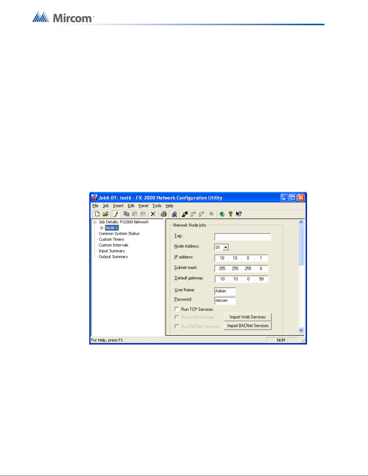
configurator. Refer to the figure below.
Ethernet Port Usage
In the configurator select the node from the Job Details tree on the left to display the Network
Node Info on the right. Each node requires a separate reserved static IP. Enter the IP address,
subnet mask and default gateway to complete the required networking information. The
subnet mask is a number that combined with the IP address identifies which network segment
the node resides on. The default gateway is the address of the router that the node connects
to. Contact your network administrator if you require assistance setting up a reserved static IP
or inputting correct values for the subnet mask and default gateway.
To allow an application, such as OpenGN or BACnet explorer, to connect and receive events
ensure that the check box "Run TCP Services" is selected.
To actively monitor the Ethernet connection for connectivity scroll down and select the
"Supervise Ethernet Connection" check box. This will create a trouble event if the node does
not detect an Ethernet connection.
6
Page 7

3.0 Web Server
The web server feature allows monitoring of the system remotely using any PC that resides on
the same network as the FACP. The web server displays much of the same information that
appears on any annunciator connected to the FACP.
3.1 Web Browser Setup
Before this feature can be accessed the job file must be configured to include the network
information described above in 2.1 Wiring/IP Settings and the "Run Web Services" check box
needs to be selected. If this box is greyed out then a CodeMeter key must be used to activate
a license using the Import Web Services button. A user name and password may also be set
in the configuration job file under the Network Node Info. If a user name and password are not
set the user name will be "admin" and the password will be "mircom" by default.
For optimal performance use the Internet Explorer browser version 6 or later, although other
web browsers are also supported. The web browser used to access the server must be set to
not cache web pages. Requiring the browser to request new information each time the server
page is accessed will ensure that the browser will not display old information that may be out
of date. To remove web site caching in Internet Explorer:
Web Server
1. Go to the browser's menu bar and select Tools, then select Internet Options at the
bottom of the drop down menu. The Internet Options dialogue box appears.
2. Under the General tab there is a section called Browsing History. From the Browsing
History section press the Settings button. A Temporary Internet Files and History
Settings dialogue box appears.
3. This dialogue box offers several options for when to check for newer versions of stored
pages. Select "Every time I visit the webpage" and press OK.
To access the webpage in an Internet Explorer web browser:
1. Enter the IP assigned to the specific panel followed by "/index.html" in the address bar.
For example if the IP address was “192.168.0.1” the full address would be “192.168.0.1/
index.html”.
2. Press enter and a prompt to enter the user name and password appears.
3. Enter the user name and password and press enter. The FACP can now be monitored
remotely.
3.2 Using the Web Server
The Web Server displays multiple pages that provide various types of information about the
function and operation of the Flex-Net system. In addition, there is information that is primarily
intended for network administrators. It allows them to access the Flex-Net system remotely for
monitoring or troubleshooting purposes. Each of these pages are described below with
accompanying screenshots.
7
Page 8
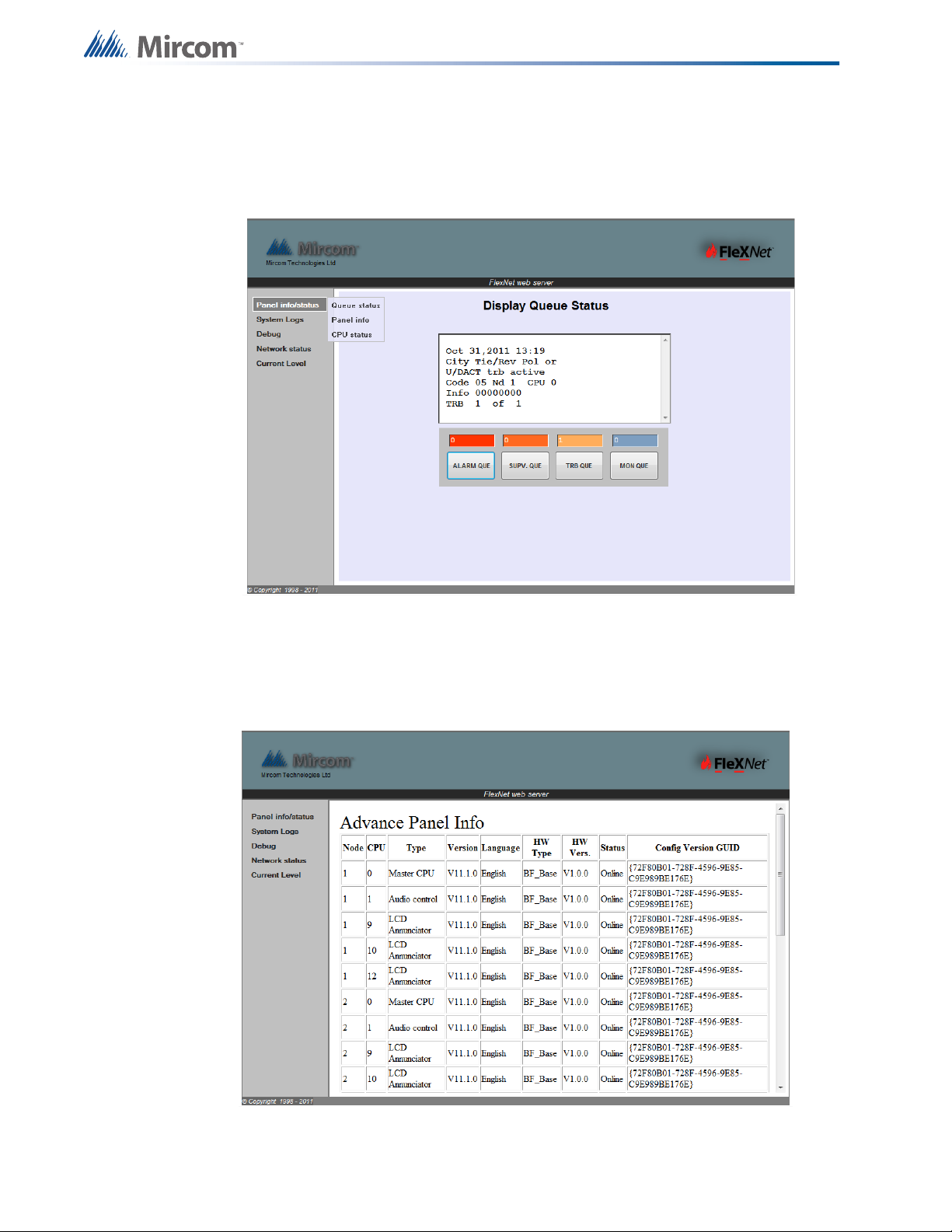
3.2.1 Queue Status
The Queue Status selection under Panel Info/Status displays the Display Queue Status page.
The Display Queue Status page shows the alarm, supervisory, trouble and monitor queues. To
browse through these queues press the corresponding button to display the list of events.
Web Server
3.2.2 Panel Info
The Panel Info selection under Panel Info/Status displays the Advanced Panel Info page. The
Advanced Panel Info page shows information about the CPUs connected to each node in the
system including firmware version and the current job via the GUID.
8
Page 9
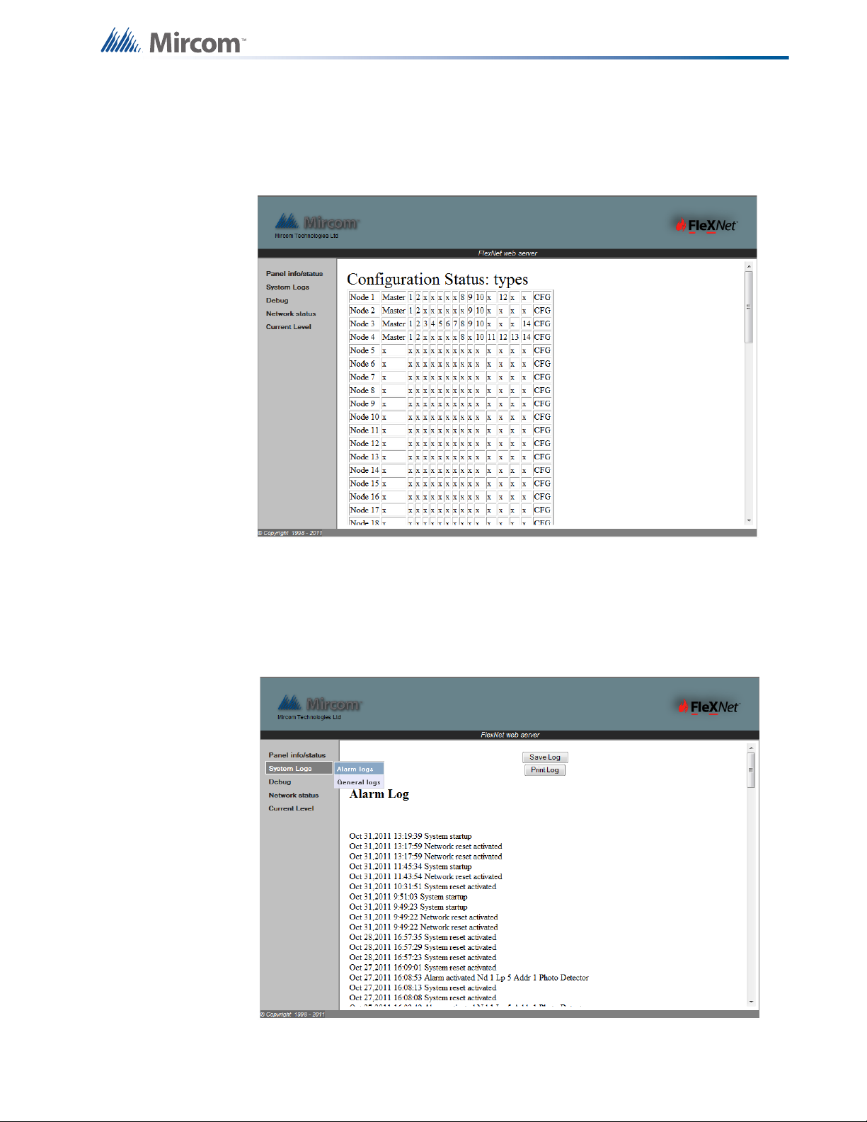
3.2.3 CPU Status
The CPU Status selection under Panel Info/Status displays the Configuration Status: Types
page. This page shows a list of the nodes that comprise the Flex-Net system. For each node
the CPUs that are in use are indicated by a CPU number beside their associated node.
Web Server
3.2.4 Alarm Logs
The Alarm Logs selection under System Logs displays the Alarm Log page. This page
displays the list of all Alarms that occur including network and system restarts. This log can be
saved to a file or printed using the appropriate buttons at the top of the page. Note that there is
a delay of a few minutes before the logs update, they are not updated in real time.
9
Page 10
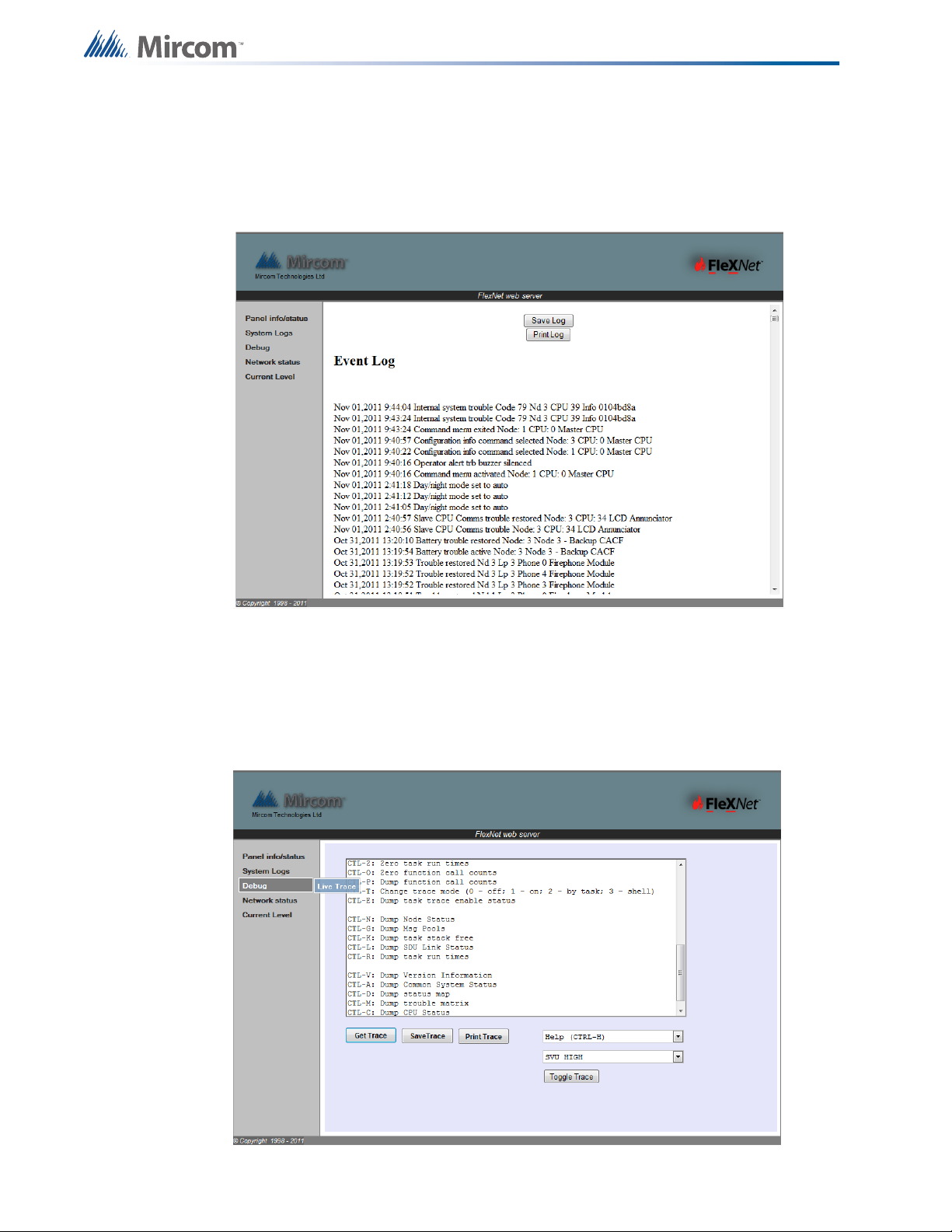
3.2.5 General Logs
The General Logs selection System Logs displays the Event Log page. This page displays a
list of all events that occur including troubles and alarms/ This log can be saved to a file or
printed using the appropriate buttons at the top of the page. Note that there is a delay of a few
minutes before the logs update, they are not updated in real time.
Web Server
3.2.6 Live Trace
The Live Trace selection under Debug displays a page that can be used by developers to
remotely monitor and debug the Flex-Net system. The type of trace can be selected from the
drop down menus and the level of the trace can be set by using the Toggle Trace button.
Press Get Trace to initiate the trace. The trace data can be saved or printed using the Save
Trace and Print Trace buttons respectively.
10
Page 11

3.2.7 Network Status - TCP
The TCP selection under Network Status displays the TCP Socket Table page. This page
displays a list containing all the connections currently being made to the web server from
remote locations. Each entry after the first represents a unique connection to the web server.
Web Server
3.2.8 Network Status - UDP
The UDP selection under Network Status displays the UDP Socket Table page. This page
displays a list containing all the BACnet applications currently connecting to the Flex-Net
system from remote locations. Each entry after the first represents a unique connection to the
web server.
11
Page 12
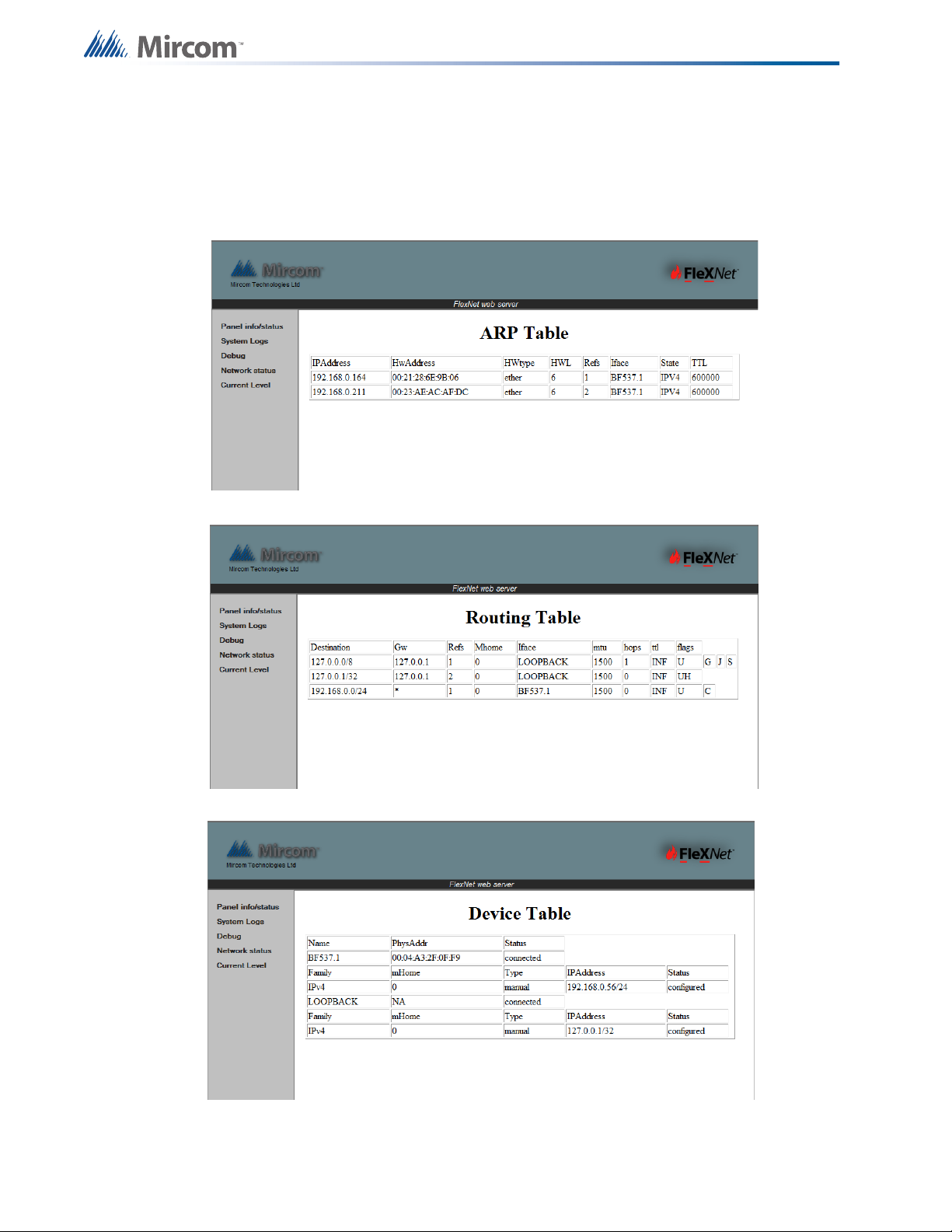
3.2.9 Network Status - ARP, Route and Devices
The ARP, Route and Devices selections under Network Status display the ARP Table,
Routing Table and Device Table pages respectively. Each of these pages contain information
intended to aid network administrators in remotely monitoring, troubleshooting and configuring
the network connection of the Flex-Net system.
Web Server
12
Page 13
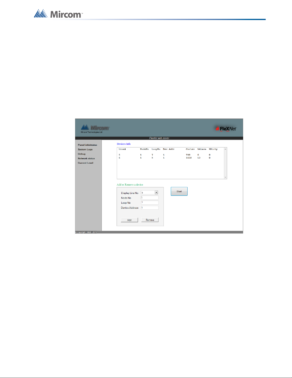
3.2.10 Current Level
The Current Level selection displays a page that can monitor individual devices. To add a
device for current level monitoring:
1. Use the Display Line No. drop down to select the line for the device to be placed on.
2. Then enter the values for the node the device is on, the loop on that node it is on and the
device address in the fields labelled Node No, Loop No and Device Address
respectively.
3. Press Add and enter information for a second device or press Start to begin monitoring.
4. The Device Info window will update with current level readings and the percentage that
the current level is at before it reaches alarm level at or beyond 100%.
Web Server
13
Page 14
4.0 BACnet
BACnet stands for Building Automation and Control NETworks (http://www.bacnet.org). It is
an object-oriented communications protocol designed to consolidate different building
regulation systems to allow for collective monitoring and control through a single application.
Building regulation systems that can support the BACnet standard include heating, ventilation,
lighting control, access control as well as fire detection and alarm systems.
The Flex-Net system is capable of interfacing with other systems that communicate through
BACnet to provide centralized control and monitoring of a building’s regulation systems. The
BACnet protocol works by adapting different communication systems into a common
communication format.
The consolidation of different communication systems is accomplished through the use of
“objects”. An object is defined as a collection of information related to a particular function that
can be uniquely identified and accessed over a network in a standardized way. The BACnet
protocol represents all information using these object data structures. Each object is defined
by a set of properties.
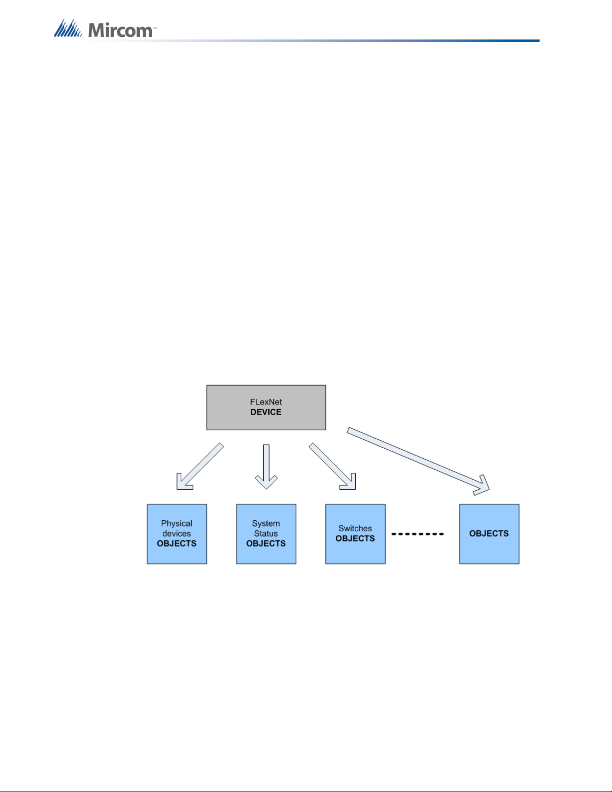
A confusion of terminology may arise when describing Flex-Net under the BACnet model.
Traditionally in the fire alarm industry the term “device” refers to things such as detectors,
strobes and alarms. For BACnet implementation, the entire Flex-Net system is modeled as a
“device” with many “objects”. The term “objects” refers to all the fire devices, system statuses
and switches connected to the Flex-Net system. This is illustrated in the figure below.
BACnet
14
Objects are all assigned properties that help define them and allow them to be monitored and
controlled. Objects can be classified into one of several different types. For example fire
devices can be subdivided into categories such as binary inputs, binary outputs, analog inputs
and analog outputs. In addition to an object type every object must be assigned an object
identifier and an object name. Depending on the type of BACnet device that the object is
associated with there will be more required properties that need to be assigned and others
that are optional.
BACnet uses a peer to peer architecture where any device can send service requests to any
other device. Protocol services include Who-Is, I-Am, Who-Has and I-Have for the purpose of
BACnet device and object discovery. These discovery service requests can be performed by
any BACnet device or object. BACnet services can provide event notifications such as
troubles or input activations. The services can also request current values from the Flex-Net
system.
Page 15
4.1 Flex-Net Configuration for BACnet
Note that the Flex-Net system is treated as a BACnet field panel and not a workstation. It does
not poll or query other BACnet field panels. Instead it replies to requests from workstations or
sends out notifications of new events.
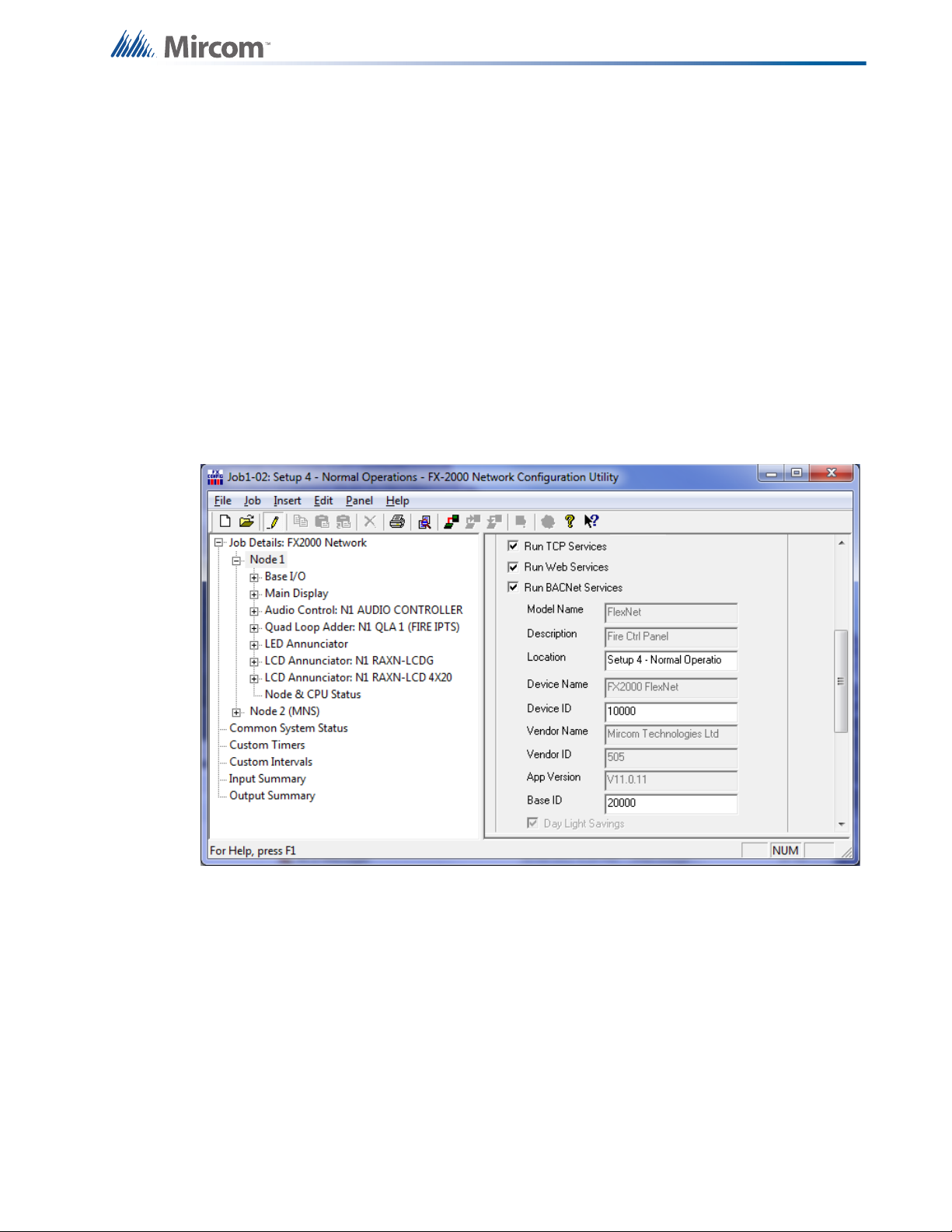
Before BACnet services can be used with the Flex-Net system, the system must be configured
correctly. Network settings must first be set up as explained in 2.1 Wiring/IP Settings. The rest
of the configuration is performed using the configurator. In the configurator select the node
from the Job Details tree on the left to display the Network Node Info on the right.
From the Network Node Info window pane on the right select Run BACnet Services and Run
TCP Services to enable BACnet. If Run BACnet Services is greyed out then a CodeMeter key
must be used to activate a license using the Import BACnet Services button. Enter a Device ID
and a Base ID in the fields that become available. The value for the Base ID is where object ID
values will start from. To ensure that the value entered for the Device ID is outside the range of
possible object IDs enter a value lower than that of the Base ID. The Device ID defines the ID
of a BACnet device meaning the FACP. Refer to the figure below.
BACnet
As an example, the following points describe how addresses are assigned to addressable
devices by the configurator:
• The BACnet protocol specifies (2
22
- 1) or 4,194,303 available address IDs.
• Out of these, each FACP node reserves 24,000 IDs.
• Out of these 24,000 IDs, 13,000 are reserved for physical devices and 11,000 are for
statuses and switches.
• Node numbering starts from 0.
• Each node can support 7 CPUs (0-6) with 1,600 IDs available per CPU.
• Each CPU can support 4 loops (0-3) with 400 IDs available per loop.
• The method for identifying fire device address IDs is described by the following:
Base ID + (Node# x 24000) + (CPU# x 1600) + (Loop# x 400) + Fire Device ID
15
Page 16
BACnet
This is for informational purposes only and is not intended to be used to identify objects or their
location. Instead the configurator can generate a BACnet XML report that includes the
address ID of each object as well as other identifying information such as node, CPU and loop
number. To generate an XML report:
1. Navigate to the configurator menu bar and select the Job drop down menu. From the
drop down menu select Export Job, the Export Current Job to a File window appears.
2. In this new window choose a location to save the file under the “Save in” drop down
menu.
3. Enter a name for the file under the “File name” drop down menu, and select “XML files
(*.xml)” under the “Save as type” drop down menu.
4. Press Save and a new window appears. In this new window select “BACnet Report Excel” and press OK.
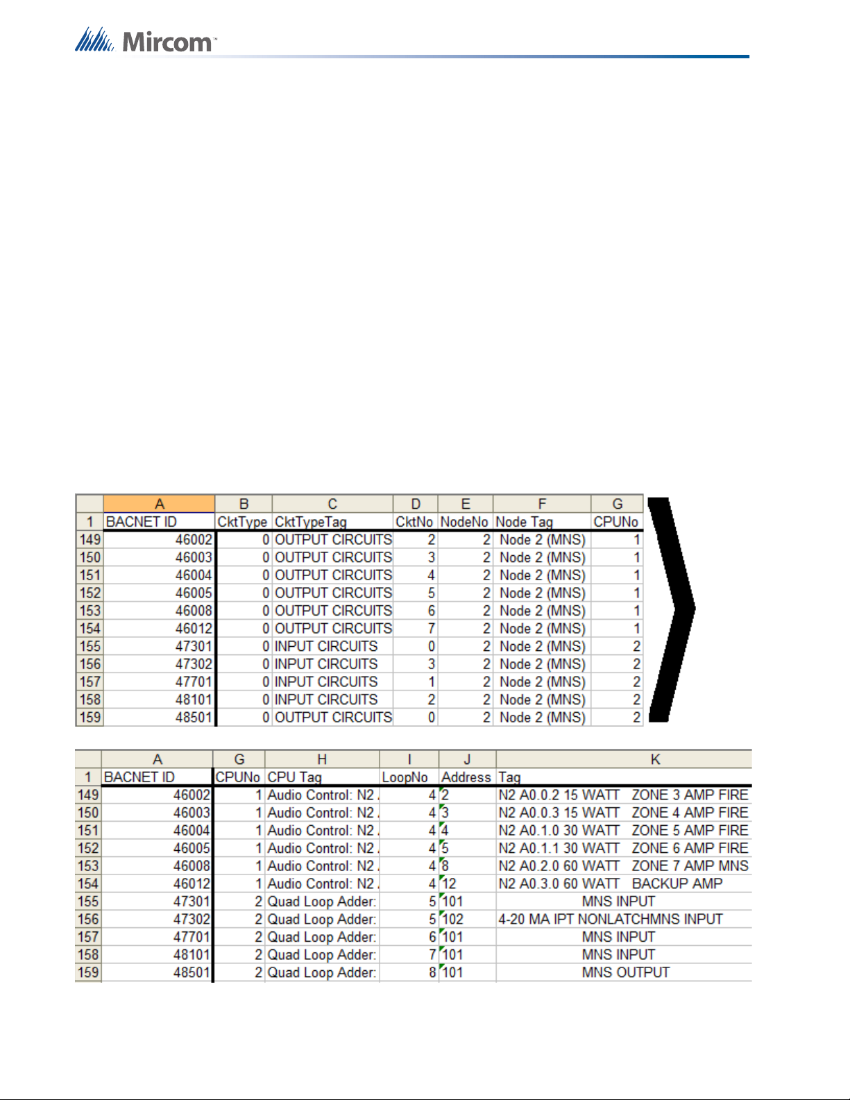
The report will appear as shown below. The first column will list the BACnet ID of each object
in the Flex-Net system. Following this column other identifying information for the object will be
listed. The NodeNo, CPUNo and LoopNo columns describe which Node, CPU and Loop
each object exists on. The Node Tag and CPU Tag columns are descriptions of the Node and
CPU respectively. The Address column lists the fire device address and the Tag column
provides a description of the object. The CktType, CktTypeTag and CktNo columns contain
information that is used internally by the Flex-Net firmware to identify the object.
16
Page 17

BACnet
The object types that Flex-Net uses are binary input, analog input, multi-state input, life safety
point and binary output. The following table identifies which fire devices are classified under
which BACnet object types.
Object Type Fire Device Types
Binary Input Conventional Input, System Status, Page Select Switches, Manual
Control Switches, Miscellaneous Input Circuits
Object
Type
Object
Properties
Analog Input and
Multi-State Input
Ion Detector, Photo Detector, Heat Detector, Laser Detector,
COPTIR, 4-20mA Module, Acclimate Detector
Life Safety Point Fire Phone, Telephone Line, Generic Input
Binary Output Amplifier, Addressable Relay, Conventional Relay, Conventional
Signal, Control
Each of these object types have an associated set of properties. These properties identify the
object and the state it is in. The table below lists the properties associated with each BACnet
object that are used by the Flex-Net system. Some of the properties below are static, while
others are dynamic and are used to determine the state the object is in. The dynamic
properties in the table are bolded.
Binary Input Analog Input Multi-State
Life Safety Point Binary Output
Input
Object
Identifier
Object Name
Object Type
Present Value
Status Flags
Event State
Out of Service
Polarity
Description
Object
Identifier
Object Name
Object Type
Present Value
Status Flags
Event State
Out of Service
Units
Description
Object
Identifier
Object Name
Object Type
Present Value
Status Flags
Event State
Out of Service
Number of
States
Description
State Text
Object Identifier
Object Name
Object Type
Present Value
Status Flags
Event State
Out of Service
Reliability
Mode
Accepted Modes
Silenced
Operation
Expected
Description
Object Identifier
Object Name
Object Type
Present Value
Status Flags
Event State
Out of Service
Polarity
Priority Array
Relinquish
Default
Description
Active Text
Inactive Text
Each dynamic object property uses different types of information to describe the state of the
property. The type of information reported can also vary between different object types for the
same object property. The following discussion describes the different values each dynamic
object property can have for the different object types.
BINARY INPUTS: The Present Value property can be in one of two states: active or inactive.
For the Status Flags property a Boolean array [_,_,_,_] is displayed with each value in the
array representing the presence (1) or absence (0) of an Alarm, Fault, Override or Out of
Service respectively. For example a signal of 1,1,0,0 indicates the presence of an alarm and a
fault. Note that for Flex-Net override is never used. For the Event State property one of three
states is possible: normal, fault or off normal.
ANALOG INPUTS: The Present Value property is represented by a raw analog value in the
form of a pulse width PW4 signal. For the Status Flags property a Boolean array [_,_,_,_] is
displayed with each value in the array representing the presence (1) or absence (0) of an
17
Page 18
BACnet
Alarm, Fault, Override or Out of Service respectively. Note that for Flex-Net override is never
used. For the Event State property one of three states is possible: normal, fault or off normal.
MULTI-STATE INPUTS: The Present Value property ranges from 0-7 and each value
indicates one of the eight possible states. For the Status Flags property a Boolean array
[_,_,_,_] is displayed with each value in the array representing the presence (1) or absence (0)
of an Alarm, Fault, Override or Out of Service respectively. Note that for Flex-Net override is
never used. For the Event State property one of three states is possible: normal, fault or off
normal.
LIFE SAFETY POINTS: The Present Value property can be in one of three states: quiet, fault
or alarm. For the Status Flags property a Boolean array [_,_,_,_] is displayed with each value
in the array representing the presence (1) or absence (0) of an Alarm, Fault, Override or Out of
Service respectively. Note that for Flex-Net override is never used. For the Event State
property one of three states is possible: normal, fault or off normal.
BINARY OUTPUTS: The Present Value property can be in one of two states: active or
inactive. The Status Flags property a Boolean array [_,_,_,_] is displayed with each value in
the array representing the presence (1) or absence (0) of an Alarm, Fault, Override or Out of
Service respectively. Note that for Flex-Net override is never used. For the Event State
property one of three states is possible: normal, fault or off normal.
Now that BACnet has been enabled and configured in the job file to be sent to the panel other
software can be used to monitor and interact with the Flex-Net system using BACnet.
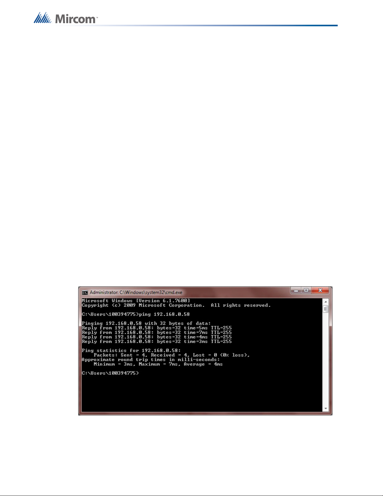
Before attempting to connect to the Flex-Net system using BACnet software ensure that there
is a network connection between the computer the software is located on and the FACP. To do
this open a command prompt window using your computer. Press Start, select Run, type
“cmd.exe” and press OK. In the command prompt window type “ping ” followed by the IP of the
FACP. If the destination host is unreachable check the network connection and make sure that
the computer and the FACP are on the same subnet with different IPs.
18
Page 19
4.2 CAS BACnet Explorer
There are many applications that can interface with BACnet devices. Three of these programs
will be described. The first program is called CAS BACnet Explorer. This program is useful for
testing, debugging and discovering BACnet networks and devices. The program can be
downloaded from the internet from: http://www.chipkin.com/cas-BACnet-explorer but it
requires a license to use. The license comes in the form of a USB key which must be plugged
into the computer the software is being used on. When installing the software the installer will
prompt for the installation of WinPcap. Allow this to install as it is part of the CAS BACnet
Explorer package.
BACnet
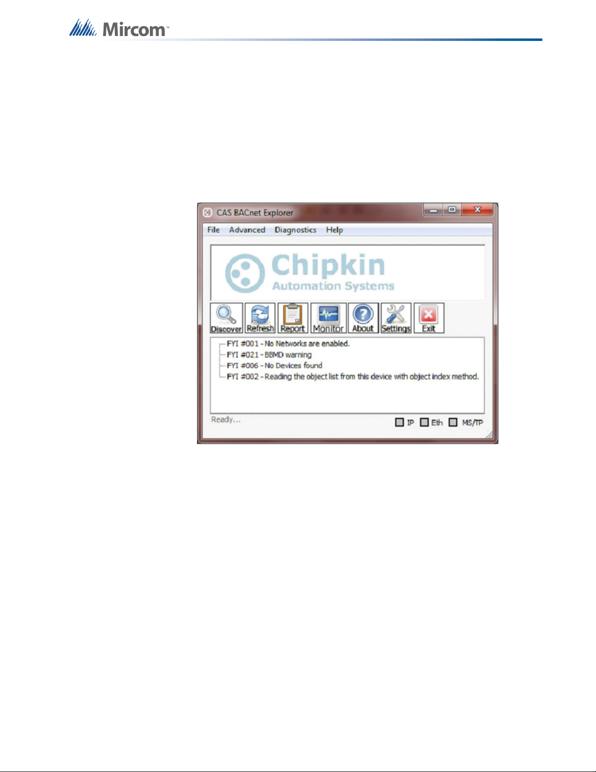
Once CAS BACnet Explorer is installed start the program. Some settings require
configuration:
1. Press the Settings button and a Settings dialogue box will appear.
2. In the Settings dialogue box press the Network tab on the left and check the BACnet IP
and the BACnet Ethernet check boxes.
3. Select the network card being used and then press OK.
The Discover function of the program identifies all objects associated with the Flex-Net
system. These objects include inputs, outputs, switches and system statuses. This function is
useful for confirming the presence and availability of all the objects associated with the FACP
and it must be performed before any FACP devices can be monitored.
1. Press the Discover button and a Discover dialogue box will appear.
2. Ensure that all check boxes on the left are selected. Select the All check box beside the
Network field.
3. In the Low Device Instance field enter the Device ID of the FACP that was set in the
configuration.
4. In the High Device Instance field enter a value one greater than the Device ID. Setting
this range ensures that only objects associated with the FACP will be discovered.
19
Page 20
BACnet
5. Press Send to begin the discovery process.
Note that sometimes the software will report errors while discovering, this will not affect the
outcome of the discovery. Once the discovery is complete the main window should display a
populated tree consisting of all the objects associated with the FACP. If the list does not
appear or is incomplete repeat the discovery process with all options selected.
The CAS BACnet explorer can also be used to monitor any changes in the properties of any of
the objects associated with the FACP. Once objects have been discovered the populated tree
can be expanded and individual objects can be selected. Each object can be expanded to
view its parameters and properties. To monitor an object right click on it and select “Add this
object to monitor list”. Repeat this for each object that needs to be monitored.
Objects will be monitored using default properties however the list of default properties may
not included all required properties. To set properties to be monitored click on the settings icon
and the Settings window appears. Use the Add and Remove buttons to select properties.
Press OK to confirm the settings.
Once objects and properties to be monitored are selected press the Monitor button in the main
window. All the objects to be monitored will be displayed in a new window titled Monitor List.
This window will display any changes in properties as they happen in real time.
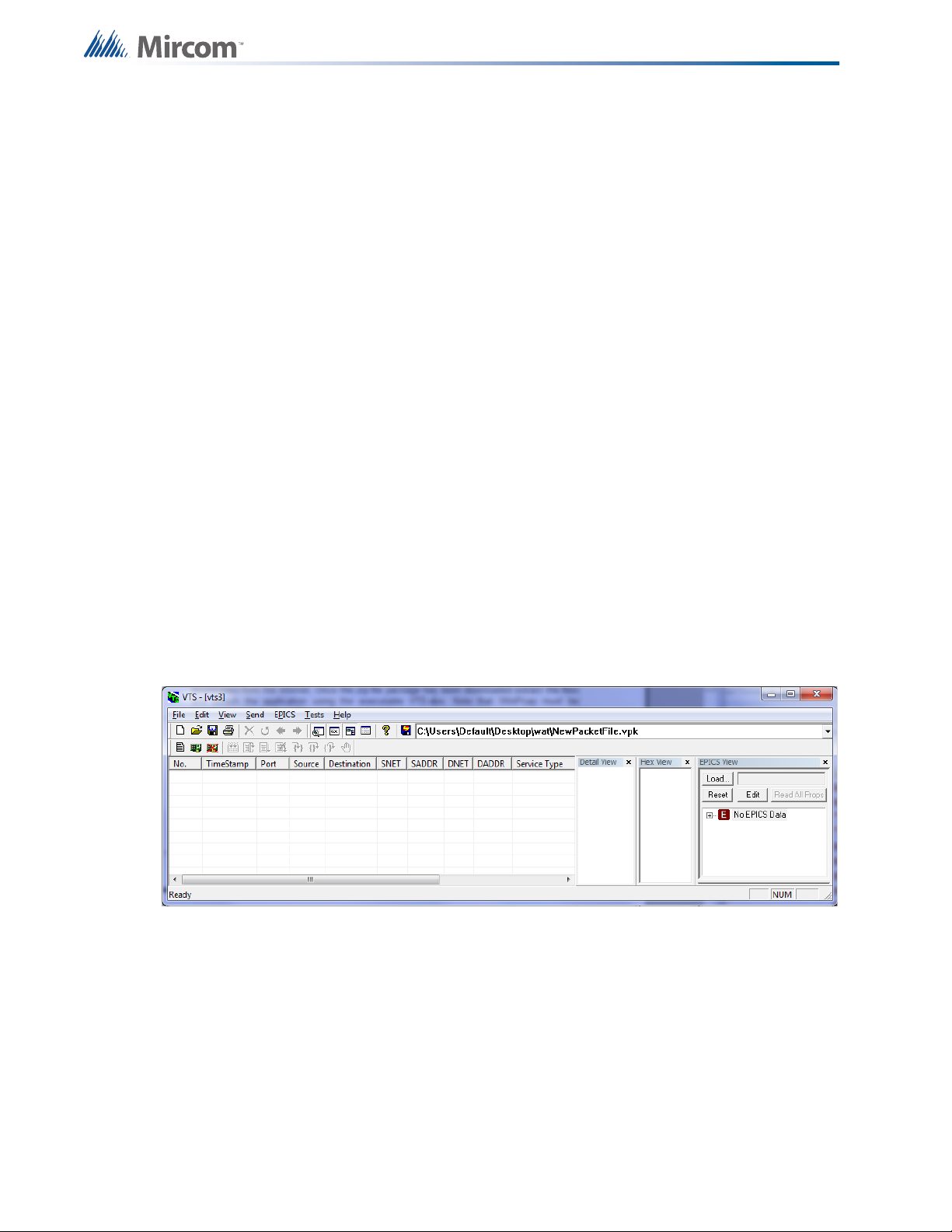
4.3 Visual Test Shell
The Visual Test Shell (VTS) is an application that is able to monitor BACnet objects and
communicate with BACnet devices to acknowledge alarms. It is freeware and can be
downloaded from: http://sourceforge.net/projects/vts/. Once the zip file package has been
downloaded extract the files and launch the application using the executable VTS.exe. Note
that WinPcap must be installed in order for the VTS application to launch.
4.3.1 Configuring Device, Port and Name Settings
1. From the taskbar select Edit then select Device. The Device Configuration window
appears.
20
2. Enter a name for the BACnet device in the Name field and its Device ID in the Instance
field.
3. Press OK to confirm your settings.
4. From the task bar select Edit then select Ports. The Port Configuration window appears.
5. Press the New button and in the Name field enter a name for the port.
6. Select the Enable check box and use the Network drop down box to select the device
that was configured in the Device Configuration window.
Page 21

7. Press the IP tab and ensure that the Interface drop down box displays the correct
network adapter.
8. Press OK to confirm your settings.
9. From the task bar select Edit then select Names. The Names window appears.
10. Press the New button and set the Address Type to Local Station if the FACP is on the
same subnet.
11. Use the Port drop down box to select the port created using the Ports menu. Enter a
name for the FACP. Enter the IP address assigned to the FACP in the configuration in
the Address field along with the port number.
12. Press OK to confirm your settings.
4.3.2 Setting up Filters
Navigate to the Edit menu and select either Capture Filter or Display Filter. The setup for each
filter type is the same, the difference being that the display filter changes what is displayed and
does not affect the log file while the capture filter directly affects what appears in the log file. To
create a new filter:
BACnet
1. Click the New button in the Filters window.
2. Select options for accepting or rejecting packets and set the Port, Address and Address
Type as before in 4.3.1 Configuring Device, Port and Name Settings.
3. Press OK to confirm your settings.
4.3.3 Acknowledging Alarms
1. Navigate to the menu bar and select Send. From the drop down menu navigate to Alarm
and Event then Acknowledge Alarm. The Acknowledge Alarm dialogue box will appear.
2. The majority of information to be filled in under the Acknowledge Alarm tab is only for log
file purposes and can be replaced with placeholder information. For the Acknowledging
Process Identifier, Event Object Identifier and Acknowledgement Source fields enter
placeholder text such as “1”.
3. Press both Time Stamp buttons and the Time Stamp window appears, enter placeholder
text such as “1” in the Time field for both windows and press OK.
4. For the Event State Acknowledged drop down select normal.
5. Select the IP tab in the Acknowledge Alarm window and select the destination FACP
using the Destination drop down menu.
6. Press Send to Acknowledge the alarm.
4.3.4 Monitoring Objects
Objects can be monitored by retrieving the current value of any property associated with an
object. This is accomplished by sending read property commands. To send a read property to
the FACP:
1. Navigate to the menu bar and select Send. From the drop down menu navigate to Object
Access then Read Property. The Read Property dialogue box will appear.
2. Under the Read Property tab press the ID button beside the Object ID field. The Object
ID dialogue box appears.
21
Page 22

3. In this dialogue box select the Object Type using the drop down menu and enter the
object’s BACnet ID under the Instance field. This is the ID described by the expression in
4.1 Flex-Net Configuration for BACnet.
4. Press OK and switch to the IP tab in the Read Property dialogue box.
5. Select the destination FACP using the Destination drop down menu.
6. Press Send to send the read property request. The request should be responded to by
the FACP with information about the object in the main VTS window.
4.4 Wireshark
Wireshark is an application that monitors and analyzes network packets. As streams of data
pass through a network the application captures the data and decodes the information
contained therein. This function can be used to troubleshoot and analyze network information.
The software is free and can be downloaded from http://www.wireshark.org/download.html.
Once the software is installed run the Wireshark application. From the menu bar select
Capture and from the drop down menu that appears select Interfaces. A new window will
appear where the network device being used can be selected. Select the appropriate network
card and press Start.
BACnet
All packets traveling through the network will now be monitored and displayed in the main
application window. To monitor BACnet packets only type “bacnet” into the filter field below the
menu bar and press Enter on your keyboard. Now only BACnet packets will be shown and all
other network traffic will be filtered out.
Select any packet to view details on its contents. The information in these packets can now be
used for troubleshooting or debugging purposes.
22
Page 23
5.0 Job Details XML Report
The job details XML is a representation of the job created in the configurator. It contains all the
CPUs and fire devices that make up the job as well as the correlations between them. The
XML format allows the job configuration to be read by a wider range of applications and
provides an alternative way to present the details of the configured job.
5.1 Generating an XML Report
1. Navigate to the configurator menu bar and select the Job drop down menu. From the
drop down menu select Export Job, the Export Current Job to a File window appears.
2. In this new window choose a location to save the file in under the “Save in” drop down
menu, enter a name for the file under the “File name” drop down menu, and select “XML
files (*.xml)” under the “Save as type” drop down menu.
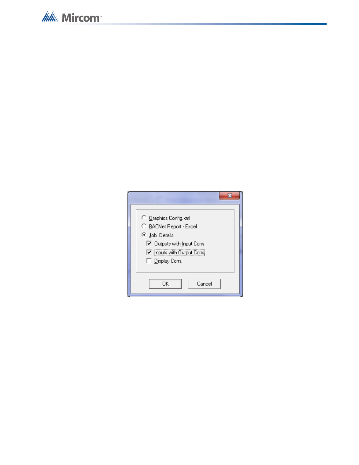
3. Press Save and a new window appears. In this new window select “Job Details”. Select
the types of correlations to include in the job details XML by selecting from the check
boxes and press OK to generate and save the file.
Job Details XML Report
23
Page 24

Mass Notification System Introduction
6.0 Mass Notification System
Introduction
The Flex-Net Mass Notification System (MNS) allows announcements and notifications to be
made to the occupants of a facility. It is intended for notification outside of regular fire
evacuation messages and signals. The MNS is able to override the fire control system in case
there is a need to communicate higher priority information. Conversely, it is possible for the fire
control system to have communication priority over MNS.
The MNS comes integrated with the fire control and monitoring system. A single MNS panel
can display both MNS and fire events but each type of event will appear separately on different
annunciator displays. The modules on the MNS panel used for MNS and fire functionality are
arranged independently from each other and are accessed via two separate doors on the
same panel. Refer to the figure below.
24
Even though the MNS panel has a fire monitoring component, fire devices cannot be
controlled by the MNS panel. Inputs for the MNS and the fire control system must reside on
loops connected to their respective nodes.
Page 25
Mass Notification System Introduction
Fire Input
- Manual Stations
- Switches
- Detectors
MNS Input
- Manual Stations
- Switches
- Other
Fire Zone
MNS Zone
Advanced Logic Equations
Fire Virtual Zone
MNS Virtual Zone
Output Hardware
- Speakers
- Horns
- Strobes
Output Hardware
- Speakers
- Horns
- Strobes
FIRE GROUP PRIORITY LEVEL 1
MNS GROUP PRIORITY LEVEL 2
MNS and the fire control and monitoring systems exist together on a single network, but it is
required that they be grouped separately on a software level. The input and output devices for
fire and MNS must be assigned to different zones and these zones must be in different groups.
Since input zones cannot activate outputs directly across a group, the MNS input zones will
not activate fire output signals and fire input zones will not activate MNS output signals.
To assign a group to a node select the node in the configurator using the Job Details tree on
the left. Create a new group or add it to an existing group by using the Network Node Info
window that appears on the right. Once the node has been assigned to a group membership,
common control switches such as system reset and total evacuation should be assigned to the
appropriate groups. This can be accomplished by selecting the node group that the switch has
been assigned to and selecting the appropriate group.
However, sometimes inputs from one group require the use of hardware present in a different
group. For example, the fire group may have inputs that require the use of amplifiers present
in the MNS panel. To communicate to the output zone across a group, virtual zones must be
used.
A virtual zone is a zone that is not correlated to any physical devices but is instead used to
communicate across groups through the use of advanced logic. Virtual zones are local to the
group that contains the outputs they intend to signal. They can monitor inputs across groups
and activate their associated outputs if the required conditions are met. The advanced logic
that drives these virtual zones consists of Boolean equations.
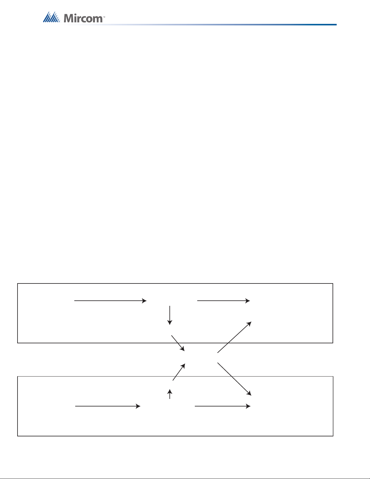
However, there may be situations where conflicts can occur. For example, two inputs may
attempt to activate the same output simultaneously. This is remedied by assigning priority to
either MNS or fire such that one will take precedence over the other. For example, if MNS has
a higher priority and a fire input is activated first then the fire output will remain active until an
MNS input is activated in which case the MNS output will take over and silence the fire output.
Fire output will resume to completion once the MNS output is cleared. Refer to the
supplementary diagram below.
25
Page 26
Boolean Equations for Mass Notification
7.0 Boolean Equations for Mass
Notification
Boolean equations are used to control the virtual zones that drive the activation of outputs
across groups. Using the Advanced Logic Editor dialog, an equation can be composed and
applied to an output circuit or a local input zone. This is done by specifying any number of local
and remote inputs zones and local input circuits (operands) and Boolean expressions
(operators).
When the result of the equation from an evaluation of the TRUE/FALSE state of all inputs is
TRUE the associated output will be energized. Note that applying an equation directly to an
output bypasses all of the regular input to output correlation processing.
Also note that the use of advanced logic does not modify the code at an executive level. These
equations are parsed and checked for syntax before being sent to the panel. The virtual input
is correlated to signals or other outputs as usual and the standard fire alarm processing is
performed by the executive control routine.
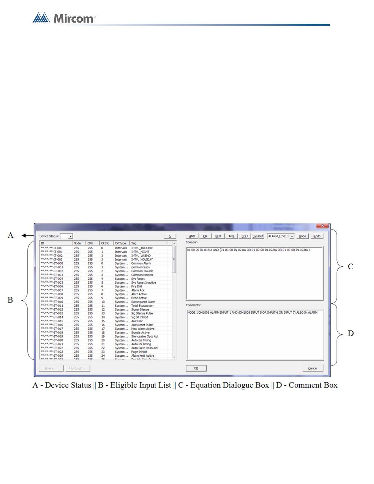
7.1 Advanced Logic Editor
The following image is a screen capture of the Advanced Logic Editor dialogue.
26
To access the Advance Logic Editor select any zone or output such as a relay and click the
Advanced Logic tab in the bottom right window then press the Edit button. The Advanced
Logic Editor dialogue appears.
Page 27

7.1.1 Device Status
The Device Status allows a user to apply a mask to any device. Masks include:
“:A" – Alarm
“:B” – Bypass
“:F” – Fault
“:L” – Level
If a mask is applied to a device then the equation will only become TRUE when the specific
status changes. For Example “07-02-01-IZ-001:B”, this alarm zone will only become TRUE
when this zone is bypassed.
To apply a mask, use the drop down and select the desired mask before moving the input into
the Equation Dialog Box. If no mask is applied, any change in status will result in the equation
becoming TRUE.
7.1.2 Eligible Input List
Boolean Equations for Mass Notification
A list of all eligible inputs that can be referenced by equations. The list consists of local input
circuits and zones, remote zones, intervals, timers, and switches.
The ID column lists identification values for all eligible inputs. An ID is assigned to each input,
interval, timer, or switch to aid in identification when referenced in the equation dialog. The
address of each is used to structure the ID.
The ID is structured in the following manner:
Node No._CPU No._Loop No._CKt Type_CKt No.
Node No. – The numerical value assigned to the node.
CPU No. – The numerical value assigned to the CPU within the node
Loop No. – The numerical value assigned to the SLC where the device is physically
connected, if applicable
CKt Type – The circuit type. This is used to distinguish between an input circuit, zone, interval,
timer or status. The following are the abbreviations used for each circuit type:
IN – Input circuit
IZ – Input zone
SW – Switch
ST – System status
IT – Interval
TM – Timer
27
Page 28

CKt No. – The numerical value assigned to each status, switch, timer, interval, zone or input
by the Flex-Net Configurator
A double asterisk “**” is used if there is no applicable value for certain ID components such as
a Loop No. for a system status.
The Node and CPU columns list the numerical value of the node pertaining to each input
device or zone. A default value of 255 is applied to system statuses, control switches, timers,
and intervals as they are global inputs which apply to the entire network.
The Ckt No column consists of numerical values assigned by the Flex-Net Configurator to
each input.
The Ckt Type column identifies the type of input. Inputs can vary from system statuses,
switches, intervals, timers, input devices, and input zones.
The Tag column includes a general description of each input that helps identify it. This aids in
constructing an equation.
7.1.3 Equation Dialog Box
Boolean Equations for Mass Notification
The Equation Dialog Box is where the logic equations are structured. To insert an input, select
the input from the Eligible Input List and click the > button above the list.
To insert an operand, select the appropriate button above the Equation Dialog Box. To insert a
System Define, use the drop down to select the appropriate system define and then click the
Sys Def button. The Undo button removes the last change to the equation. The Redo button
reapplies the last removed change to the equation.
7.1.4 Comment Box
The comment box is used to attach comments to the advanced logic equation. Comments are
important for quickly explaining the intended function of an equation. This will allow for easier
troubleshooting and quicker review of the configuration later on.
7.2 Advanced Logic Example
7.2.1 Objective
To create an advanced logic equation using a combination of operators. The advanced logic
equation will be part of a virtual input zone. It will reference inputs that exist in a separate
group from the equation's virtual input zone. This virtual input zone will be referenced by an
output in its group that will activate when the equation that drives the zone becomes true.
28
7.2.2 Procedure
1. Create an alarm input zone in the same group as the outputs that are to be activated.
Tag the zone "Virtual Alarm Zone 1".
2. Create three input devices and tag them appropriately.
3. Select the alarm input zone and then select the Advanced Logic tab. Click the Edit
button and the Advanced Logic Dialog Box appears.
4. Select the Device Status mask ":A" for alarm.
Page 29
Boolean Equations for Mass Notification
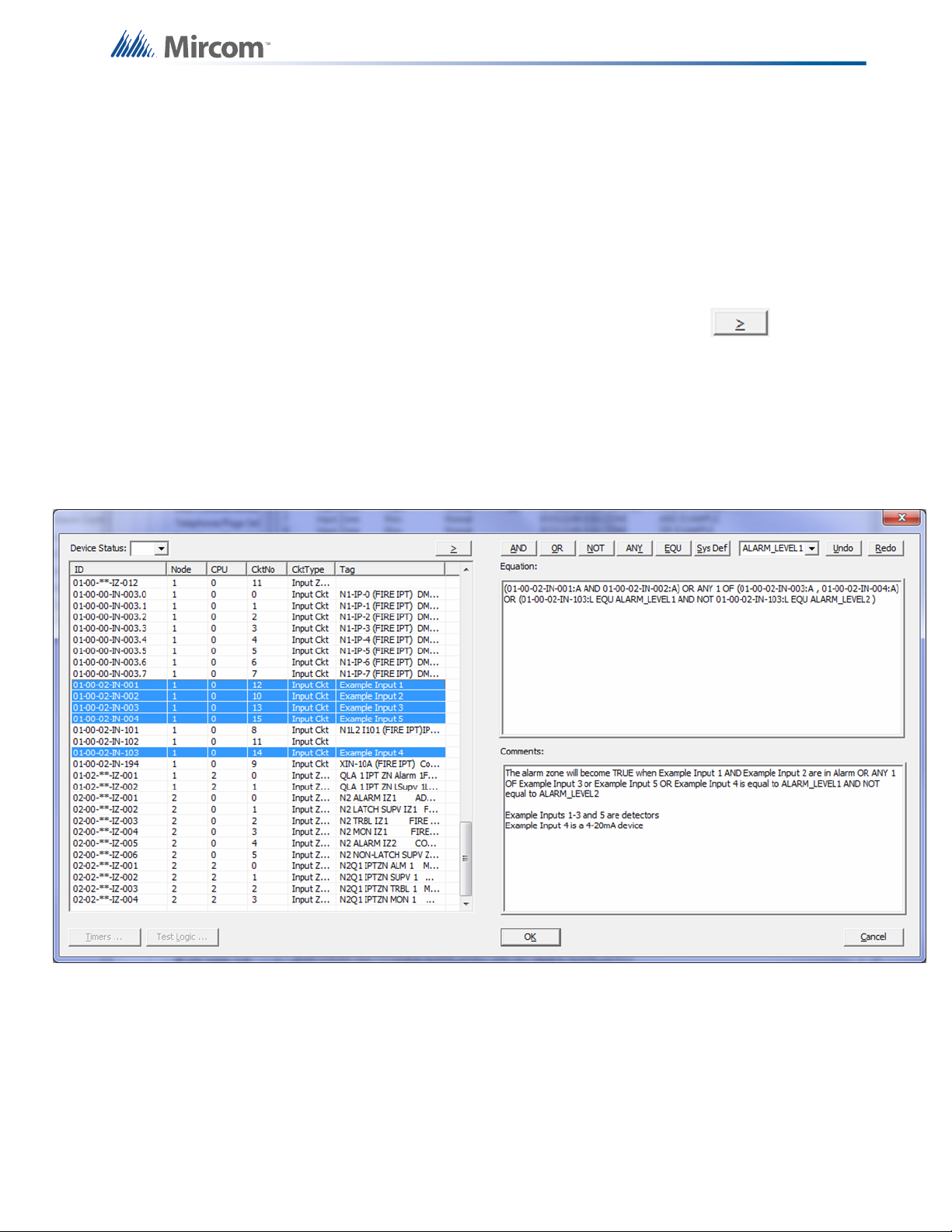
5. Select the device tagged Example Input 1 and the device tagged Example Input 2 by
holding down the CTRL key and press the AND operator. Complete with brackets.
6. Press the OR operator
7. Select the devices tagged Example Input3 and Example Input 5 by holding down the
CTRL key followed by the ANY operator. The number in the ANY operator can be
modified to require more than 1 input state to become true. Change this value to 2.
8. Press the OR operator and insert an open bracket.
9. Select the Device Status mask ":L" for level.
10. Select the device tagged Example Input 4 and press the chevron button.
11. Press the EQU operator then select ALARM_LEVEL1 and press the Sys Def operator.
12. Press the AND operator and then press the NOT operator.
13. Select the device tagged Example Input 4 and press the chevron button.
14. Press the EQU operator then select ALARM_LEVEL2 and press the Sys Def operator.
15. Insert a close bracket.
16. Add a comment in the comment box and press OK.
The alarm zone will become TRUE when Example Input 1 AND Example Input 2 are in Alarm
OR ANY 1 OF Example Input 3 or Example Input 5 OR Example Input 4 is equal to
ALARM_LEVEL1 AND NOT equal to ALARM_LEVEL2. Example Inputs 1-3 and 5 are
detectors and example Input 4 is a 4-20mA device.
17. Select an output in the same group as the virtual zone, right click on it and Add
Correlations.
18. Select the virtual input zone and press Add. This output will now activate every time the
virtual input zone activates due to the equation being satisfied.
29
Page 30
8.0 Digital Messages
Digital messages can be created in the Job Details section of the configurator. To create a
digital message go to the Audio section of the Job Details window and press the Set Up
button. The Audio Setup window appears. In this window press the Manage Messages button.
The Manage Messages menu lists each of the digital messages that can be used for the job
being configured. A new digital message can be created and added to the list using the Add
button. An existing digital message can be modified by selecting it and pressing the Edit
button. A digital message can be deleted from the list by pressing the remove button.
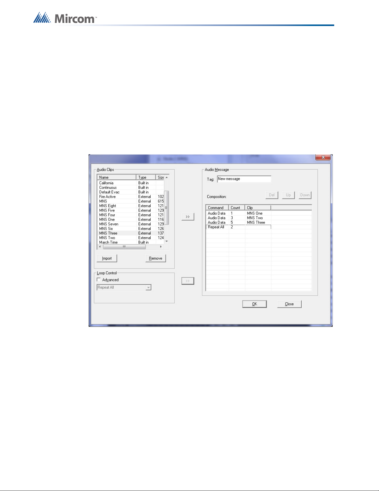
In the Manage Messages window press the Add button or select a message to edit then press
the Edit button. Refer to the figure below.
Digital Messages
30
In the new window either press the Import button and select an audio file to include in the
message or select an audio clip from the files already imported into the Audio Clips menu. All
audio files must be in .wav format. The .wav format must be sampled at 11.025 KHz, 16-bit
mono, ADPCM 4-bit. This format is suited for compressing voice. Alternatively, PCM (RAW) 16-
bit mono can be used for non-voice messages such as a whoop signal or sweep. A program
called Audacity is able to convert most audio file formats into the required .wav format. The
software is freeware and can be downloaded from http://audacity.sourceforge.net/.
Once an audio clip has been imported into the Audio Clips list it can be used to compose a
message. A message can be composed out of a single or out of multiple audio files. Select the
audio clip and move it over to the Composition list by pressing the dual chevron button beside
the Audio Clips list. The audio files in the Composition list can be reordered by selecting them
in the list and pressing the Up and Down buttons. The audio clips can be removed from the
Composition list by selecting them and pressing the Del button. An audio clip can also be set
to repeat a certain number of times, to do this double-click on the count column beside the
audio clip in the Composition list and enter the number of times to repeat it. The entire
Page 31

Digital Messages
composition can also be set to repeat by pressing the dual chevron button beside the Loop
Control menu.
More advanced methods of ordering audio files in a composition exist. Check the Advanced
option under Loop Control to enable it. With Advanced mode selected the Loop Control drop
down now has 4 loop levels that can be applied to audio clips in a nested loop format. The
Advanced mode also adds the Seq and Loop Base columns to the Composition window on the
right.
The inner most loop command is the highest loop level used in the composition. As audio clips
and loop commands are added to the composition they are given a sequence number in the
Seq column starting from 0. Loop commands are applied to audio clips above them starting
from the sequence number specified in the Loop Base column. Loop commands that are at an
outer level compared to the inner most used loop are applied to the entire composition above
that contains inner level loops. Loop levels and audio clips can be reorganized in the
composition window using the Up and Down buttons. They can be removed using the Del
button. Enter a name for the audio message in the Tag field and press OK to finalize the
composition, add it to the list of messages and to exit the menu. Refer to the figure below
where the entire composition is repeated once more.
31
Page 32

9.0 Relay Pulsing
Relay pulsing may be required for various setups where a relay will turn ON (close) and then
OFF (open) after a single switch press. An example of relay pulsing is to activate a prerecorded digital message using the first pulse and then to deactivate the message with the
second pulse, simulating a maintained switch.
9.1 Relay Pulsing Sequence
The sequence is initiated by either a switch or input circuit changing to an active state. The
changing of state from standby to active satisfies the first condition resulting in an input zone
tagged “Latch A” to become active and maintain its state. Maintaining the state or latching is
performed through advanced logic. See 10.0 Zone Latching.
Once “Latch A” is active, a timer called “Latch A Timer” is started. The timer is used to turn ON
the output relay once it starts running. Once the timer expires, the output relay will turn OFF.
Therefore, the timer is usually set for a short period of time in order to simulate a pulse such as
3 seconds.
Relay Pulsing
The second pulse is generated by the second press or the input circuit changing state to
inactive standby. This will satisfy the second condition and activate “Latch B”. “Latch B” will
start a second timer called “Latch B timer” in a similar manner as before. This will pulse the
relay for the second time.
9.2 Producing a Relay Pulsing Sequence
1. Create a monitor input zone. This zone will be activated based on the status of the
switch or input circuit. It will also be referenced in the advanced logic equations for both
latching zones. Tag the zone appropriately such as “Input Switch”
2. Create two (2) timers; Latch A timer and Latch B timer. Specify a time in seconds, for
example 3 seconds. Tag each timer appropriately
3. Create another monitor input zone. This zone will be “Latch A”. Highlight the zone and
select the advanced logic tab. Create an equation as shown:
01-00-**-IZ-007 OR (01-00-**-IZ-011 AND NOT **-**-**-TM-021 EQU TIMER_EXPIRED)
Where,
01-00-**-IZ-007 – Input Switch Zone
01-00-**-IZ-011 – Latch A Zone
**-**-**-TM-021 – Latch B Timer
Note – Latch B timer is referenced in the equation in order to un-latch the zone during
the second pulse
32
4. Create another monitor input zone. This zone will be “Latch A”. Highlight the zone and
select the advanced logic tab. Create an equation as shown:
**-**-**-TM-020 EQU TIMER_EXPIRED AND (NOT 01-00-**-IZ-007 OR 01-00-**-IZ-
012)
Where,
**-**-**-TM-020 – Latch A Timer
Page 33

Relay Pulsing
01-00-**-IZ-007 – Input Switch Zone
01-00-**-IZ-012 – Latch B Zone
5. Highlight Latch A Timer and click the edit button for Advanced Logic. Select the Latch A
Zone. This will start the timer once the Latch A Zone becomes active.
6. Highlight Latch B Timer and click the edit button for Advanced Logic. Select the Latch B
Zone. This will start the timer once the Latch B Zone becomes active.
7. Highlight the output relay and select the Advanced Logic tab. Create an equation that will
be true if either Latch A Timer or Latch B Timer is running.
**-**-**-TM-020 EQU TIMER_RUNNING OR **-**-**-TM-021 EQU TIMER_RUNNING
Where,
**-**-**-TM-020 – Latch A Timer
**-**-**-TM-021 – Latch B Timer
8. Correlate the input ckt or switch to the monitor zone “Input Switch”. If multiple switches
are to be used, an equation can be added to the monitor zone to reduce interference
between switches. Refer to the example below:
01-00-00-IN-008 AND NOT ANY 1 OF ( 01-00-**-IZ-007 , 01-00-**-IZ-009 , 01-00-**-IZ010 )
Where,
01-00-00-IN-008 – Input ckt 1
01-00-**-IZ-007 – Input Switch 2
01-00-**-IZ-009 – Input Switch 3
01-00-**-IZ-010 – Input Switch 4|
This equation is optional however this will reduce interference between switches. For
example, if the first switch is pressed generating the first pulse and then, while switch 1
is maintained, switch 2 is pressed. This could cause issues if the pulses were turning
ON/OFF digital messages as the first message would be overridden
33
Page 34

10.0 Zone Latching
Zone latching is a useful technique that can be applied to latch normally non-latching zones
such as monitor, trouble, and non-latching supervisory zones. Latching zones can be used to
maintain outputs or timers even if the original input is no longer active.
An example of when a latching zone is used would be to add a strobe delay for a period of
time after a page has occurred. The input being the page active status would initially activate a
zone. This zone is correlated to the output strobes that would activate with the activation of the
zone. However, the zone would need to remain active once the page active status is
deactivated therefore latching the zone is required. A timer can also be used to unlatch the
zone upon expiring.
10.1 Zone Latching Sequence
The basic sequence involves an initiating device, status, or zone and the zone used to latch
itself. The “latching zone” must have multiple methods of becoming active, either by the
activation of the initiating device/status/zone or by the “latching zone” itself. This is done
through advanced logic. Refer to the example below.
Zone Latching
The equation shown is specified in the advanced logic tab of the latching zone, 01-00-**-IZ011
01-00-00-IN-007 OR 01-00-**-IZ-011
01-00-00-IN-007 – Initiating device
01-00-**-IZ-011 – Latching Zone
Note: the latching zone is referenced in the advanced logic equation for the latching zone. This
allows the zone to latch itself.
Once the initiating device becomes active, the latching zone will become active as the
advanced logic equation would be satisfied. If the initiating device becomes de-active or is
restored, the latching zone will remain active as the equation would still be satisfied. Thus the
zone is latched. A system reset would be required to unlatch the zone similar to a normally
latching zone such as alarm.
By modifying the advanced logic equation with a timer, the latch can be set to unlatch upon the
expiration of the timer. For example,
01-00-00-IN-007 OR (01-00-**-IZ-011 AND NOT **-**-**-TM-021 EQU TIMER_EXPIRED)
The equation would remain satisfied as long as timer 21 does not expire. Upon expiration of
timer 21, and the initiating device is restored, the equation will no longer be satisfied and the
latching zone would be restored.
34
Page 35

10.2 Producing a Zone Latching Sequence
1. Create an initiating device. This can be a monitor zone, input circuit, or a status such as
All Call.
2. Create a non-latching zone such as a monitor zone. This will be used as the “Latching”
zone.
3. Highlight the “Latching” zone, and select the Advanced logic tab.
4. Create an equation that will activate the “Latching” zone by the initiating zone, input, or
status OR by the “Latching” zone itself.
Advanced Logic Equation shown for the “Latching” zone, 01-00-**-IZ-011
**-**-**-SW-017 OR 01-00-**-IZ-011
**-**-**-SW-017 – All Call Common switch
01-00-**-IZ-011 – Latching Zone
The Latching Zone, 01-00-**-IZ-011, will latch once the All Call switch is activated. If the
All Call is restored, the latch will remain latched until a system reset is initiated.
Zone Latching
35
Page 36

Autonomous Control Unit and Local Operating Consoles
11.0 Autonomous Control Unit and Local
Operating Consoles
The Flex-Net Mass Notification System (FX-MNS) interfaces with the user through the use of
the Autonomous Control Unit (ACU) or any one of multiple Flex-Net Local Operating Consoles
(FX-LOCs). Each FX-LOC is located remotely from the main FX-MNS panel allowing
messages to be sent from multiple locations in a building. The ACU and FX-LOCs are able to
monitor FX-MNS events and can broadcast announcements and pre-recorded digital
messages throughout a building.
Each FX-LOC contains switching and input module combination to broadcast pre-recorded
digital messages. The ACU contains a switch adder module to broadcast pre-recorded digital
messages. In addition to this each unit contains a paging module to broadcast
announcements and a display to monitor FX-MNS events.
11.1 Broadcast Priority
Broadcasting announcements or digital messages using an ACU overrides any broadcast
already in progress by an FX-LOC. Broadcasting announcements or digital messages using
an FX-LOC occurs on a first come first serve basis between the different FX-LOC terminals. If
one FX-LOC is being used to broadcast, another FX-LOC cannot be used until the first is no
longer in use. The following list identifies broadcast priorities from highest to lowest.
1. ACU announcement via paging microphone
2. ACU highest priority digital messages (priority is set on a software level)
3. ACU lowest priority digital messages (priority is set on a software level)
4. FX-LOC announcement via paging microphone
5. FX-LOC highest priority digital messages (priority is set on a software level)
6. FX-LOC lowest priority digital messages (priority is set on a software level)
11.2 ACU and LOC Configuration
The paging microphone for the ACU connects directly to the main board through a ribbon
cable connection and is given priority over the FX-LOC paging microphones and all digital
messages on a firmware level.
The ACU broadcasts digital messages using an IPS switch adder module. Each button on the
switch adder module can be configured as a zone switch in the configurator. For each zone
switch a priority level can be assigned and a digital message can be attached. The switch
adder module takes precedence over the switching and input module combination used by the
FX-LOC. For example, a priority of 10% assigned to a zone switch on the IPS switch adder
module used by the ACU will have a higher priority than a priority of 90% assigned to a zone
correlated to the input module used by the FX-LOC. Refer to the figure below.
36
Page 37

Autonomous Control Unit and Local Operating Consoles
The paging microphones used by the FX-LOCs are hardwired to the board belonging to the
ACU paging microphone. Their hierarchy is configured on a firmware level to have lower
priority than the IPS switch adder module messages used by the ACU but a higher priority
than the FDS switching module messages used by the FX-LOC.
The FX-LOC broadcasts digital messages using an FDS switching module. Each switch on
this switching module is hardwired to inputs on an input module that are correlated to input
zones in the configuration. Each input is correlated to its own input zone with a digital
message attached to each zone. Priority for FX-LOC digital messages is set between the input
zones. For example, an input zone with an assigned priority of 70% will over ride an input zone
with an assigned priority of 50%. Refer to the figure below.
37
Page 38

11.3 ACU Operation
To broadcast a pre-recorded digital message press a button on the selector with the
appropriate message. Buttons should be labelled to indicate the content of the message that
will play. The message will be broadcasted and loop continuously until the system is reset or a
higher priority operation is performed.
To broadcast an announcement remove the paging microphone from its receiver and key the
microphone to activate the amplifiers. Speak into the microphone to broadcast the
announcement. The Page Ready LED will be on to indicate it is in use as soon as the
microphone is keyed. The ACU paging microphone has the highest priority and will override all
other operations upon activation.
11.4 LOC Operation
To broadcast a pre-recorded digital message select a switch with the appropriate message
and move it to the ON position. Switches should be labelled to indicate the message that they
will play. The message will be broadcasted and loop continuously until the system is reset or a
higher priority operation is performed.
Autonomous Control Unit and Local Operating Consoles
To broadcast an announcement remove the paging microphone from its receiver and key the
microphone to activate the amplifiers. Speak into the microphone to broadcast the
announcement. Only one microphone can be used at a time.
If the Page Ready LED is on before the microphone is removed from the receiver then another
microphone is in use. If the LED is off then there isn’t a microphone in use indicating that they
are all available. If the LED turns on only after the paging microphone is removed then that
microphone is now active.
38
Page 39

12.0 Firmware Loading
The following items are required in order to load the firmware onto a panel:
• PC with a serial port
• Serial Cable
• QX-5000N RS-232 Debug Tool
•HyperTerminal
Before loading a new firmware onto the panel ensure that the PC being used has
HyperTerminal installed. Firmware needs to be individually loaded onto each board that
contains a CPU: the main board, the audio card, the quad-loop adder and the RAXN-LCD.
Refer to Appendix A: Hardware Changes for information about changes in component
positions from Flex-net Phase I.
12.1 Main Board Firmware
1. Connect the serial cable from the PC directly to the main board.
Firmware Loading
2. Run the HyperTerminal software on the PC.
3. In the HyperTerminal start up prompt set the correct communications port and select a
baud rate of 115200.
4. Reset the processor on the main board by shorting the reset jumper. The jumper only
needs to be shorted momentarily, it should be normally open. During the reset process
press any key in HyperTerminal to enter the Flex-Net shell.
5. Input the following set of commands after the "flexnet>" prompt appears and press enter
after each one: "sf probe 1", "sf erase 0x200000 0x600000", and "run sflash".
6. Navigate to the HyperTerminal menu bar and select Transfer, then select Send File. A
Send File window appears.
7. Specify the location of the binary file that contains the new main board firmware by
entering the file path or by pressing the Browse button and searching for the file. Set the
Protocol to "Ymodem" and press Send.
8. When the "flexnet>" prompt reappears type in "reset" and press enter.
12.2 Audio Card Firmware
1. Connect the serial cable from the PC to the QX-5000N RS-232 Debug Tool and connect
the 8-pin head to the P4 RS-232 Debug port on the audio card. Ensure that the keyed
extrusion on the connector lines up with the one on the port.
2. Run the HyperTerminal software on the PC.
3. In the HyperTerminal start up prompt set the correct communications port and select a
baud rate of 115200.
4. Reset the processor on the audio card by shorting the reset jumper, JW4. The JW4
jumper is the closest one to the 8-pin port and only needs to be shorted momentarily, it
should be normally open. During the reset process press any key in HyperTerminal to
enter the Flex-Net shell.
5. Input the following set of commands after the "flexnet>" prompt appears and press enter
after each one: "sf probe 1", "sf erase 0x200000 0x600000", and "run sflash".
39
Page 40

6. Navigate to the HyperTerminal menu bar and select Transfer, then select Send File. A
Send File window appears.
7. Specify the location of the binary file that contains the new audio card firmware by
entering the file path or by pressing the Browse button and searching for the file. Set the
Protocol to "Ymodem" and press Send.
8. When the "flexnet>" prompt reappears type in "reset" and press enter.
12.3 Quad-Loop Adder Firmware
1. Connect the serial cable from the PC to the QX-5000N RS-232 Debug Tool and connect
the 8-pin head to the P5 RS-232 Debug port on the quad loop adder board. Ensure that
the keyed extrusion on the connecter lines up with the one on the port.
2. Run the HyperTerminal software on the PC.
3. In the HyperTerminal start up prompt set the correct communications port and select a
baud rate of 115200.
4. Reset the processor on the quad-loop adder by shorting the reset jumper JW1 on the
quad-loop adder main board. The jumper only needs to be shorted momentarily, it
should be normally open. During the reset process press any key in HyperTerminal to
enter the Flex-Net shell.
Firmware Loading
5. Input the following set of commands after the "flexnet>" prompt appears and press enter
after each one: "sf probe 1", "sf erase 0x200000 0x600000", and "run sflash".
6. Navigate to the HyperTerminal menu bar and select Transfer, then select Send File. A
Send File window appears.
7. Specify the location of the binary file that contains the new quad-loop adder firmware by
entering the file path or by pressing the Browse button and searching for the file. Set the
Protocol to "Ymodem" and press Send.
8. When the "flexnet>" prompt reappears type in "reset" and press enter.
12.4 RAXN-LCD and RAXN-LCDG Firmware
1. Connect the serial cable from the PC directly to the main board.
2. Run the HyperTerminal software on the PC.
3. In the HyperTerminal start up prompt set the correct communications port and select a
baud rate of 115200.
4. Reset the processor on the quad-loop adder by shorting the reset jumper JW1. The
jumper only needs to be shorted momentarily, it should be normally open. During the
reset process press any key in HyperTerminal to enter the Flex-Net shell.
5. Input the following set of commands after the "flexnet>" prompt appears and press enter
after each one: "sf probe 1", "sf erase 0x200000 0x600000", and "run sflash".
40
6. Navigate to the HyperTerminal menu bar and select Transfer, then select Send File. A
Send File window appears
7. Specify the location of the binary file that contains the new annunciator firmware by
entering the file path or by pressing the Browse button and searching for the file. Set the
Protocol to "Ymodem" and press Send.
8. When the "flexnet>" prompt reappears type in "reset" and press enter.
Page 41

13.0 Configuration Loading
The following items are required in order to load a configuration onto a panel:
• PC with a serial or USB port
• Serial Cable or USB Cable
•UIMA Tool
• Registered CodeMeter Key
• FX-2000 Network Configuration Utility V11 or greater
Before loading a configuration job ensure that the PC being used has the FX-2000 Network
Configuration Utility software installed. Plug in the registered CodeMeter key to the PC and
start the Configuration Utility.
If an RS-232 cable is used in conjunction with a serial port to communicate between the panel
and the PC then the correct communications port needs to be set. To set the communications
port open the Network Configuration Utility and select File from the menu bar and select User
Preferences from the drop down menu. A new dialogue box appears. In the drop down box
labelled Serial Port select the port the RS-232 uses to connect to the PC. Press OK to confirm
the selection.
Configuration Loading
Connect the RS-232 cable or the USB cable to the UIMA then connect the 10-pin head of the
UIMA to the last CPU in the CPU chain that starts from the main board.
Establish a connection between the CPUs in the FACP and the PC. To do this press the
Connect icon in the task bar or navigate from the menu bar to Panel then select Connect from
the drop down menu. Once this connection has been established the configuration can be
loaded onto the panel. To load the active configuration onto the panel select the Send icon in
the task bar or navigate to the menu bar and select Panel then from the drop down menu
select Send Job. Specify which node to send the job to in the dialogue box that appears. Once
the job is verified and sent the software will prompt if you wish to make it the active job on the
panel. Each CPU on the panel can hold up to 3 jobs, if there are already 3 jobs on a CPU one
must first be removed to make room for the new one. To remove one of the 3 jobs stored on a
CPU use the configurator and select Panel from the menu bar. From the drop down menu
select Manage Jobs. Use the new dialogue box to delete one of the jobs.
If a job is not set as the active job from the configuration loading stage it can later be set to be
the active job using the interface on the FACP. To change the active job using the FACP
access the main display on any node or an annunciator for any node in the system. Press the
Menu button and scroll down using the arrow keys to the option titled "11 Choose Config".
Scroll through the available configurations using the arrow keys and confirm a selection by
pressing the Enter button. This will use change the configuration for all the nodes in the
system. To set configurations for individual nodes the Network Configuration Utility must be
used.
41
Page 42

14.0 Hardware Layouts
RAX-1048TZ
Programmable Zone
LED Annunciator Module
IPS-2424
Programmable Input
Switches Module
Display Modules
FDX-008
Fan Damper Module
Each of these Display Modules occupy one display
position and mount to the display cutouts on the
following chassis:
FX-2017-12N Mid-Size Main Chassis
FX-2009-12N Large Main Chassis
ECX-0012 Expander Chassis for FX-2009-12
These modules can also be mounted in the standard
BB-5000 cutouts (with brackets), as well as in the
BB-1000 enclosures (requires RAX-LCD as a driver)
.
DSPL-420
Narrow Main
Display Module
DSPL-2440
RAXN-LCD
Network Remote LCD
Annunciator Module
Narrow Graphic
Display Module
RAXN-LCDG
Graphic Remote LCD
Annunciator Module
The Flex-Net Phase II Fire Alarm Control System contains two major types of nodes: Fire
Nodes and Mass Notification Nodes. The entire system is modular and any number of
combinations are possible when building a system. The Fire Nodes can use the BBX-1024,
the BBX-1072, the BB-5008 and the BB-5014 model backboxes. The Mass Notification Node
uses the BBX-FXMNS model backbox.
The system can also include Audio-Signalling Enclosure Cabinets that are able to connect to
either node and use the QBB-5000XT backbox. Local Operating Consoles use the FX-LOC
backbox and are used with Mass Notification Nodes.
14.1 Display Modules
These modules can be installed on the door of any node with display module slots. The
specific number and combination of display modules varies depending on the application and
requirements of the job.
Hardware Layouts
42
Page 43

14.2 Paging and Fire Fighter Telephone Modules
Paging and FireFighter Telephone Modules
QMP-5101N
QAZT-5302
Addressable Telephone
Selector Module
QMP-5101NV
QMT-5302NV
Vertical Network
Paging Control Unit
Vertical Network
Telephone Control Unit
Network Paging
Control Unit
QMT-5302N
Network Telephone
Control Unit
These modules can be installed on the door or inside any node with paging module slots. The
specific number and combination of paging and fire fighter telephone modules varies
depending on the application and requirements of the job.
Hardware Layouts
14.3 Adder Modules
These modules can be installed inside any node with adder module slots. The specific number
and combination of adder modules varies depending on the application and requirements of
the job.
Adder Modules
ALCN-792M
Quad Loop Adder
Motherboard*
DM-1008A
Eight Initiating
Circuit Module
Polarity Reversal/City Tie Module
(Mounts above the ribbon cable on the Main Board)
PR-300A
ALCN-792D
Quad Loop Adder
Daughter Board*
SGM-1004A
Four Indicating
Circuit Module
Each of these Adder modules occupy one module
slot and mount inside the following chassis unless
otherwise specified:
FX-2003-12N Compact Main Chassis
FX-2017-12N Mid-Size Main Chassis
FX-2009- 12N Large Main Chassis
ECX-0012 Expander Chassis.for FX-2009-12
FNC-2000
Network Interface
Controller Module
RM-1008A
Eight Relay
Circuit Module
FOM-2000-SP
Single Port Digital
Network Fiber
Optic Module
UDACT-300A
Digital Alarm
Communicator
Module
* The ALCN-792D
mounts directly onto
the ALCN-792M
43
Page 44
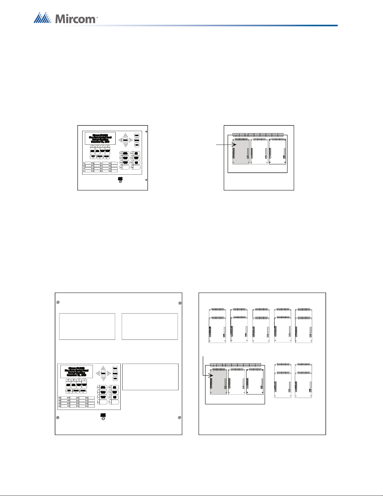
14.4 BBX-1024 Fire Node Backbox
FX-2003-12N Compact Main Chassis
(Mounts in the BBX-1024 Enclosure)
FleXNet Main Board
Exterior View Interior View
Slot is reserved for PR-300A.
If none is required, this slot
can be used to mount any of
the adder modules.
Supports 3
Adder Modules.
123
The BBX-1024 is the smallest enclosure available. It contains the FX-2003-12N Compact
Main Chassis along with batteries for emergency operation. The FX-2003-12N Compact Main
Chassis contains the main display, mother board, adder modules and the transformer. It fits
directly into the BBX-1024 backbox. The outer dimensions of the BBX-1024 fit within 26.3” X
14.8” X 4.6”.
Hardware Layouts
14.5 BBX-1072 Fire Node Backbox
The BBX-1072 enclosure is larger than the BBX-1024. It contains the FX-2017-12N Mid-Size
Main Chassis along with the batteries for emergency operation. The FX-2017-12N Mid-Size
Main Chassis contains the main display, mother board, adder modules and the transformer. It
fits directly into the BBX-1072 backbox. The outer dimensions of the BBX-1072 fit within 33.9”
X 26.4” X 6.5”.
FX-2017-12N Mid-Size Main Chassis
(Mounts in the BBX-1072 Enclosure)
Exterior View Interior View
Cutout to mount
display module
Cutout to mount
display module
Cutout to mount
display module
Slot is reserved for PR-300A. If none is required, this slot
can be used to mount any of the adder modules.
1
23
89101112
1314151617
45
67
Supports 3 Display Modules. Supports 17 Adder Modules.
44
FleXNet Main Board
Page 45

14.6 BB-5008 Fire Node Backbox
Cutout to mount
display module
Cutout to mount
display module
FX-2009-12N Large Main Chassis
(Mounts and occupies 4 display positions in BB-5008 or BB-5014 Enclosures)
Exterior View
Interior View
Slot is reserved for PR-300A. If none is required, this slot
can be used to mount any of the adder modules.
Supports 2 Display Modules.
Supports 9 Adder Modules.
4
231
56
789
FleXNet Main Board
ECX-0012 Expander Chassis for FX-2009-12N
(Mounts and occupies 2 display positions in BB-5008 or BB-5014 Enclosures)
Supports 2 Display Modules. Supports 12 Adder Modules.
Cutout to mount
display module
Cutout to mount
display module
Exterior View Interior View
1
2
34
56
789101112
The backplate can support 12 Adder Modules or any 2
of the following 3 options: 6 Adder Modules, 1 Main Board
and 3 Adder Modules, 1 Telephone Network Card
and 1 Audio Network Card
The Paging and FireFighter Telephone Modules mount in the BB-1000 or BB-5000 series enclosures. These modules require brackets
for mounting. The brackets are attached to the backplates of the enclosures. The FX-2017-12N Mid-Size Main Chassis does not have
provisions for these brackets since adder module are mounted to the backplate. The same is true for the FX-2009-12N Main Chassis
and ECX-0012 Expander Chassis since there are adder modules mounted on the backplate. In order to mount the Paging and
FireFighter Telephone modules, order the CCH-5008 or CCH-5014 Custom Mounting Kits which will provide the proper dead front as
well as the brackets on the backplate. These modules can also be mounted int he BB-1000 enclosures.
Mounting of Paging and FireFighter Telephone Modules
Exterior View
Interior View
The BB-5008 enclosure is larger than the BBX-1072. It can use the FX-2009-12N Large Main
Chassis combined with ECX-0012 Expander Chassis for additional display modules and the
CCH-5008/CCH-5014 Custom Mounting Kits for paging and fire fighter telephone modules.
The FX-2009-12N Large Main Chassis can be substituted for two ECX-0012 Expander
Chassis with the main display being replaced by the DSPL-420 Narrow Main Display module.
The outer dimensions of the BB-5008 fit within 38.0” X 32.5” X 7.5”.
Hardware Layouts
45
Page 46

Hardware Layouts
Exterior View
Interior View
Cutout to mount
any display module
BB-5008 Sample Layout
FleXNet
Cutout to mount
any display module
Cutout to mount
any display module
Cutout to mount
any display module
Cutout to mount
any display or
paging module
Cutout to mount
any display or
paging module
Cutout to mount
display module
Cutout to mount
display module
FX-2009-12N Large Main Chassis
(Mounts and occupies 4 display positions in BB-5008 or BB-5014 Enclosures)
Exterior View
Interior View
Slot is reserved for PR-300A. If none is required, this slot
can be used to mount any of the adder modules.
Supports 2 Display Modules.
Supports 9 Adder Modules.
4
231
56
789
FleXNet Main Board
The modular nature of a fire node allows for many different configurations and combinations of
modules depending on the requirements of the job. The figure below is a sample layout for the
BB-5008 although many other layouts are possible.
14.7 BB-5014 Fire Node Backbox
46
The BB-5014 enclosure is the largest available backbox. It can use the FX-2009-12N Large
Main Chassis combined with ECX-0012 Expander Chassis for additional display modules and
the CCH-5008/CCH-5014 Custom Mounting Kits for paging and fire fighter telephone
modules. The FX-2009-12N Large Main Chassis can be substituted for two ECX-0012
Expander Chassis with the main display being replaced by the DSPL-420 Narrow Main
Display module. The outer dimensions of the BB-5014 fit within 61.5” X 32.5” X 7.5”.
Page 47

Hardware Layouts
ECX-0012 Expander Chassis for FX-2009-12N
(Mounts and occupies 2 display positions in BB-5008 or BB-5014 Enclosures)
Supports 2 Display Modules. Supports 12 Adder Modules.
Cutout to mount
display module
Cutout to mount
display module
Exterior View Interior View
1
2
34
56
789101112
The backplate can support 12 Adder Modules or any 2
of the following 3 options: 6 Adder Modules, 1 Main Board
and 3 Adder Modules, 1 Telephone Network Card
and 1 Audio Network Card
The Paging and FireFighter Telephone Modules mount in the BB-1000 or BB-5000 series enclosures. These modules require brackets
for mounting. The brackets are attached to the backplates of the enclosures. The FX-2017-12N Mid-Size Main Chassis does not have
provisions for these brackets since adder module are mounted to the backplate. The same is true for the FX-2009-12N Main Chassis
and ECX-0012 Expander Chassis since there are adder modules mounted on the backplate. In order to mount the Paging and
FireFighter Telephone modules, order the CCH-5008 or CCH-5014 Custom Mounting Kits which will provide the proper dead front as
well as the brackets on the backplate. These modules can also be mounted int he BB-1000 enclosures.
Mounting of Paging and FireFighter Telephone Modules
Exterior View
Interior View
The modular nature of a fire node allows for many different configurations and combinations of
modules depending on the requirements of the job. The figure below is a sample layout for the
BB-5014 although many other layouts are possible.
BB-5012 Sample Layout
Exterior View
Cutout to mount
any display or
paging module
Cutout to mount
any display
module
Cutout to mount
any display
module
Cutout to mount
any display
module
Cutout to mount
any display or
paging module
Cutout to mount
any display or
paging module
Cutout to mount
any display or
paging module
Cutout to mount
any display
module
Cutout to mount
any display
module
Cutout to mount
any display
module
Cutout to mount
any display or
paging module
Cutout to mount
any display or
paging module
Interior View
47
Page 48

14.8 BBX-FXMNS Mass Notification Node Backbox
Cutout to mount
any display
module
Cutout to mount
any display
module
Cutout to mount
any display
module
Cutout to mount
any display
module
Cutout to mount
any display
module
Cutout to mount
any display
module
Cutout to mount
any display
module
Exterior View
Interior View
FX-MNS Sample Layout
Audio and Telephone
Network Cards and
Audio Ampliers
Main Board and 9
Adder Modules
Transformer
Batteries
The BBX-FXMNS backbox is used for the mass notification node. It can be populated with 2
paging modules, 9 adder modules and 7 display modules as indicated by the figure below. It
also supports the addition of 4 audio amplifiers along with audio and telephone networking
cards. The outer dimensions of the BBX-FXMNS fit within 63.5” X 22.5” X 9.5”.
Hardware Layouts
48
Page 49

14.9 QBB-5000XT Audio Signalling Cabinet
This future audio cabinet can provide additional audio amplification for speakers using audio
amplifiers and increased power output for strobes and other signalling devices using a booster
power supply. It can be connected to and controlled by any other node. The outer dimensions
of the QBB-5000XT fit within 63.5” X 28.0” X 9.5”.
Hardware Layouts
Audio and Telephone
Network Cards and
Audio Ampliers
INX-10AC
Booster Power
Supply
49
Page 50

14.10 FX-LOC Local Operating Console
IM-10
Input Module
RAXN-LCD
LCD Network
Annunciator
QMP-5101N
Network Paging
Microphone
FDS-008
Fan/Damper
Switching Module
These operating consoles are intended for use in mass notification. They can mount 3
modules on the deadfront door. These modules are usually a RAXN-LCD annunciator and a
QMP-5101N paging microphone in conjunction with either a QAZT-5302 selector panel or a
FDS-008 switch module and IM-10 input module combination. The paging microphone is for
broadcasting announcements, while pre-recorded digital messages can be played using the
selector panel or the switch/input module combination. The figure below shows the setup with
the switch/input module combination.
Note that the deadfront and door can be installed such that they open either to the left or to the
right as required. The outer dimensions of the FX-LOC fit within 25.0” X 15.0” X 7.0”.
Hardware Layouts
50
Page 51

Hardware Layouts
51
Page 52

Flex-Net Phase II brings along both new modules and expanded capabilities for existing ones.
Some components involved in loading of the configuration or troubleshooting operations have
been moved to new locations on some of the boards. Updates have been made to the RAXNLCD Annunciator and the ANC-5000 Audio Network Controller. The ALCN-792M Quad Loop
Adder is a new module which will also be described.
RAXN-LCD Annunciator
The two terminal blocks labelled P6 and P7 each require a jumper to prevent a display
mismatch trouble. The jumper locations are outlined in the figure below.
Appendix A: Hardware Changes
Appendix A: Hardware Changes
Jumper Locations
RAXN-LCD
Network Remote LCD
Annunciator Module
51
Page 53

JW7
JW8
IN
OUT
JW5
JW4
P13
P11
P3 For Future Use
P6 RS-485
P10 RS-485
P4 RS-232 Debug
Ethernet Port
P7
P8 H_Speed Audio
Plugs into the
QMB-5000N
Backplane
Connect
RS-485 cable
from P3 on the
main fire alarm
board to P6 IN
on this board
(daisy chain
fashion) and
from P10 OUT
to next main
fire alarm
board or to
next adder
board
Connects to TNC-5000 Telephone
Network Controller Module
+ - + - + - S
+ - S + - L
+ - S+ - S
Alternate
Power
IN
G.A.
Input
IN
RS-485
PAGING BUS
MIC
PTT
IN OUT
SW1
1
8
ON
Heartbeat
FX-2000 COMM RX
FX-2000 COMM TX
QX-5000/CLASS D RX
QX-5000/CLASS D TX
QX-5000 RX
Status Page Bus IN
Status Page Bus OUT
System OK
RESET/CPU Fail
Input Level
Jumper s JW7 and
JW8 normally shorted
to be removed for
microphone input
LEDs for
Information
P13 Ethernet
Port for Future Use
JW4 Jumper Factory
Use Only, Leave Open
JW5 Jumper Watchdog , Leave Shorted
NOTE: All connectors not shown on this drawing are for factory use only.
P4 For Factory
Use Only
High Speed Audio
Bus Connects to
Main Board P16
G.A. Input and
RS-485 are for
Future Use
ANC-5000 Audio Network Controller
The main change to this module is the addition of an Ethernet port. Affected components are
the DIP switch, the watchdog jumper and the reset jumper. The DIP switch has been reversed
from its previous position such that switch 1 is where switch 8 used to be. The positions of the
watchdog jumper and the reset jumper have been swapped with each other. Refer to the
figure below.
Appendix A: Hardware Changes
52
Page 54
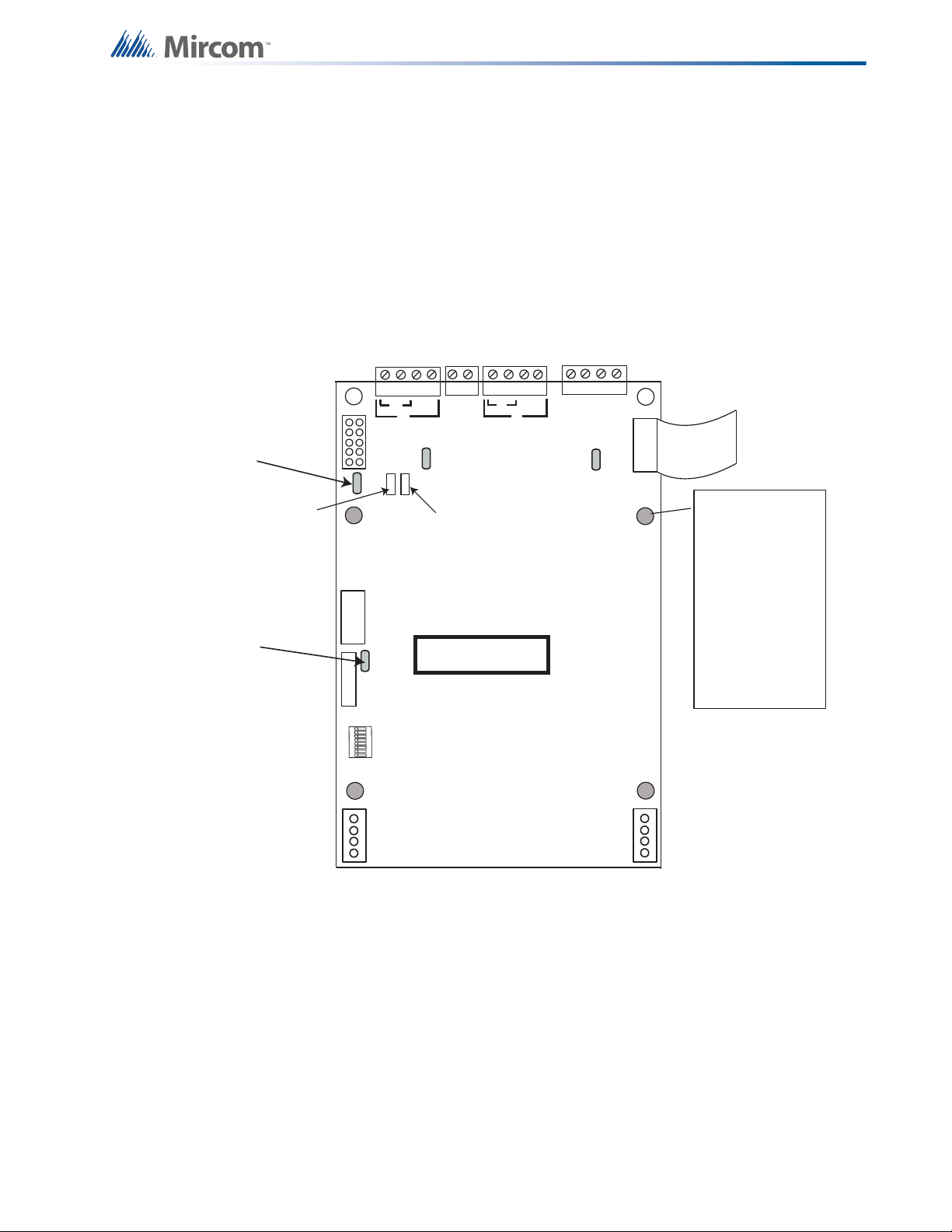
ALCN-792M Quad Loop Controller Module
+ - + -
S S + - + -
ALARM OUT
LOOP 1
LOOP 2
RS-485
P4
P2
P6
P1
P3
RS-485
ADDRESS
DIP SWITCH
RS-232
Debug
Interface
Loop 1
Active LED
Loop 2
Active LED
Four shaded
mounting holes are
for Daughter board
ALCN-792D
Top 2 holes and
bottom 2 holes are
used for the ALCN792 Quad Loop
Adder module
mounting
JTAG PORT
DIP SWITCHES ARE FOR THIS
BOARD’S ADDRESS. SW1-1
IS THE LEAST SIGNIFICANT
DIGIT (BINARY). ACTIVE POSITION IS ON. REFER TO LT-894.
P5
SW1
POWER CABLE
(OUT)
POWER CABLE
(IN)
JW2- normally shorted, a
jumper is here to enable
watchdog timer.
JW1- normally open,
pins are momentarily
shorted to reset
hardware.
B
A
A
B
8
1
Green ashing
RS-485 heartbeat
LED
Green ashing
heartbeat LED for
on board processor
OUT
CABLE IN
Daughter Board
Connector
COM (-)
Note: The RS-232 and JTAG
Ports are for factory use only
This is a new module that supports four loops as opposed to the two loops that were be
supported by the ALC-396S Dual Loop Controller Module. The changes described are
compared to the ALC-396S. The P2 Power OUT connector has been moved. The watchdog
and the rest jumpers have also been relocated. There are module additions that did not exist
before such as the JTAG port and the RS-232 Debug Interface. The ALCN-792M is paired with
another board called the ALCN-792D. This is a daughter board which mounts on top of and
connects directly to the ALCN-792M. Refer to the figure below for component positions on the
ALCN-792M.
Appendix A: Hardware Changes
53
Page 55

Appendix B: Using the Configurator
Appendix B: Using the Configurator
Overview
In order to operate as a fire alarm, a fire alarm panel must be loaded with firmware and
configuration data. A set of configuration data, to uniquely describe and control a given set of
hardware, is called a Job. The Configurator allows the user to create and manage jobs. It also
allows the user to send firmware to a panel and all its related nodes and CPUs
On the first use of the configurator the user is prompted for the paths and file names where
jobs, backups, the database, etc. are to be stored. Registry entries remember many of the
user’s preferences.
The configurator is typically run on a portable notebook or lap top computer that is taken to the
job site and connected to the panel. The technician prepares a job using the configurator’s
Graphical User Interface. The job can then be sent to the panel. The same or a different
authorised technician can later retrieve the job from the panel, modify it and send it back.
The job repository is a Relational Database (MS-Access). Jobs can be imported or merged
from another database, copied, deleted, and archived in various formats. A job can be printed,
or two versions of a job can be compared.
GUI - Major Components
The configurator uses a familiar Microsoft Windows Graphical User Interface (GUI) to present
a job. The screen is divided into (max.) three panes.
On the left of the screen, the job is represented as a tree, similar to a file explorer. At the
highest level in the tree are the Nodes and CPUs. Under each node are its components Annuniciators, Loop Controllers, etc. Some items are further subdivided, for example, an
annunciator into display adders and a loop controller into loops.
Some items in the tree do not directly represent a physical component. For example, tree
nodes exist for input and output summaries and for common controls.
The top right pane is used to display the details of the currently selected tree node. This can
be a form view or a list view. For example, this pane is used to list the devices on a loop
controller (list view) and to display the options and messages of a main display (form view).
The third, bottom right pane is used to show correlations from an item selected in the top right
pane, where appropriate. For example, when a loop is selected in the tree, the top right pane
would show all of its devices or circuits. When one or more input circuits are selected in the
list, then the bottom pane would show the output circuit(s) to which this is correlated.
In addition to standard menus (File, Edit, etc), a specialised menu hierarchy (Job, Panel,
Tools) is provided for such functions at Create New Job, Delete Job, Connect to Panel, etc.
54
A tool bar provides convenient short cuts to the more frequently used functions
Standard keyboard short cuts and mouse operations are supported for such oprations as copy
and paste, drag and drop, etc.
Page 56

Appendix B: Using the Configurator
Edit Menu
The Edit Menu contains the following commands.
Some commands may be disabled (greyed) depending on what items are selected on the user
interface.
Name Short cut Description
Delete Item Del Deletes the currently selected item.
Modify Item Ctrl+M
If the currently selected item is a row in an editable list, then
the first changeable cell is selected and prepared for editing.
Copy Ctrl+C Copies the selected item(s) to the clipboard.
Paste Ctrl+V Pastes items from the clipboard to the selected destination.
Paste Special Ctrl+Shift+V
Similar to Paste: Opens the Paste Special dialog to allow
defaults to be changed before pasting.
File Menu
The File Menu contains the following commands:
Name Short cut Description
Backup database makes a copy of the Master Database in
the File folder specified in the User Preferences. The backup
file will have a name of the form YYYY-MM-DD.mdb. The
Backup
Database
back up can be used by the Restore Database command to
recover all of the jobs in the database. The Import command
can be used to recover selected jobs from a backup. Backup
your Master Database often and store a copy of the resulting
file on a CD or other media.
Restore
Database
Restores the database from a backup copy. Note: This
operation will replace the entire contents of the current,
working datbase with the backup.
To ensure optimal performance, you should compact and
Compact
Database
repair your database on a regular basis. If you have purged
job versions or deleted jobs, Compacting the Database will
regain the space occupied by those records.
User
Preferences
Specifies User Preferences, such as the location of
database, backups, job files, etc.
Print Ctrl+P Print the active job.
Print Preview Display a Print Preview of the active job.
Print Setup Select the printer, paper size and orientation for a print job.
Exit Closes the configurator.
55
Page 57

Appendix B: Using the Configurator
Insert Menu
The Insert Menu contains the following commands.
Some commands may be disabled (greyed) depending on what items are selected on the user
interface.
Some items may be suppressed depending on the product.
Name Description
Add Network
Nodes
Add Loop
Controllers
Add
Annunciators
Add Display
Adder
Nodes Add a network node to the job.
Add an Addressable or Conventional Loop Controller to the selected
network node.
Add an LCD or LED Annunciator to the selected network node.
Add a Display Adder to an Annunciator or Base Panel.
Add UDACT Add UDACT capability to the selected network node.
Context Dependent
Add Device If the selected tree item is a device loop, add a device or circuit.
Add Message
Add
Correlations
Add a Message if the selected tree item is a remote annunciator that can
accept Custom Messages.
Launch a dialog that allows correlations to be added to the selected
devices or display items.
Job Menu
The Job Menu contains the following commands:
56
Name Short cut Description
This command will open the Create Job dialog which will
New Job Ctrl-N
allow you to start a new job. The new job can be based on a
supplied template or on an existing job.
Open Job Ctrl+O This command will open an existing job from your database.
Imports a selected job/version from an external database or
Import Job
serialized job archive and converts the job to the current
version if necessary.
Export Job Ctrl+E
Exports the current job in one of two formats: A single job
database file, or a compact, serialized archive format.
Make a copy of the current job, assigning it the next highest
version number. The user is prompted for mandatory
New Version Ctrl+W
comments and may also override the Author field. The Job
Name cannot be changed. The new version is un-locked for
editing.
Page 58

Name Short cut Description
Appendix B: Using the Configurator
Delete Job
Version
Version
History
Compare Job
Version s
Convert Job
Validate Job
Edit Job
Ctrl+D
This command permanently deletes the current Job / Job
Version from the database
Display the Version History (Date, Author, Comments) for
the current job.
Compare two versions of the same job, or two similar jobs of
different lineage.
Convert a job between two models. Produces a new version
of the current job.
This action performs all of the steps normally performed
when preparing to send a job to the panel.
Toggle the lock on a job that is protected against
unintentional edits or has been down loaded to a panel.
Panel Menu
The Panel Menu contains the following commands.
Name Short cut Description
This command will establish a connection between the
configuration tool and the panel, enabling most of the other
Connect Ctrl+L
commands in this menu. Remember to disconnect when you
are finished, as a trouble will be indicated on the fire alarm
panel as long as the laptop is connected.
Send Job Ctrl+S Build the job and send the configuration to the panel.
Get the job from the panel and store it on the configuration
Get Job Ctrl+G
tool's database. The job becomes the current job, shown in
the user interface.
Panel
Information...
Displays detailed information about the panel to which the
configuration tool is connected.
Displays information about the security key for those
Security Key
Information...
products that support a key. The user must have entered the
correct PIN when prompted - either when configurator was
started or when the key was inserted - to enable this
command.
Upgrade
Firmware...
BDM
Upload...
Loads firmware to the panel from a firmware archive file.
Upgrade the firmware using the BDM interface. Only used
for upgrading Ver 7.XX to Ver 2.X.X FX2000 firmware.
57
Page 59

Appendix B: Using the Configurator
Tools Menu
The items under the Tools Menu are used mainly for troubleshooting and diagnostic purposes
by the factory.
Name Short cut Description
Extract All DB
Extracts the latest version of every job to individual database
files.
Validate All Ctrl+S Validates the latest version of every job on the database.
Build Job Ctrl+B
Build Job (old
version)...
Builds the job, assuming the latest product version, creating
a ".c" file in the Job Build folder.
Builds the job ".c" file for a specified, older product version.
Link Statistics Displays the connection link statistics
Toggle the current state of the "dump on send" option.
Log Send
Causes the ".c" file to be produced and dumped on a Get
Job.
Log Get
Toggle the current state of the "dump on get" option. Causes
the ".c" file to be produced and dumped on a Send Get.
Log Comms Toggles logging of serial communications.
Trace
Display
Structure
Toggles the current state of the trace option. When turned on
this causes debug information to be written to a trace file.
This command will display a dialog that will allow you to view
and log panel data structures.
Toggles the "Use External Bus" setting. When turned on, this
External Bus
signals that the configurator is connected to the External
Bus of the panel.
Note: The Tools menu is only available if you checked the Show Tools Menu option. See User
Preferences
Add Amplifier
This dialog is displayed in response to an Add Amplifier command.
58
Page 60

Appendix B: Using the Configurator
Select the amplifier type. Choose from a single 60 Watt amp., 2*30 Watt or 4*15.
Choose the bin and slot for the location of the amplifiers. The program will suggest the next
available, suitably aligned location, but you can choose another that does not immediately
follow those amplifiers that are already configured.
Check the silencable box if the new amplifiers can be silenced.
Click the add button to add the amplifiers. The dialog remains open so that you can add more.
The Slot and Bin locations are recalculated.
Add Audio
This dialog is displayed in response to an Add Audio command.
Master Hand Set: You must specify whether the Audio Controller will support a master
handset (there must be at least one per job). If you choose to support a master handset, it will
consume one of the five lines of the controller.
Conventional Phones or Voice Lines: You must specify whether the four (or five) lines are to
be configured as conventional phones or as voice lines to serve addressable phone modules.
After the Audio Controller is added you can still edit these attributes, or change just some of
the lines between voice and conventional.
Add Circuit Adder
This dialog is displayed in response to an Add Circuit Adder command, or an Add Device
when the selected tree item is a conventional (hard wired) loop.
Examples:
Add 8 Input Adder - 8 Ckts: Will add additional DM-1008A Input Module with 8 Class B (4
Class A) Input Circuits
Add Supv Opt.adder 4 Ckts: Will add a SGM-1004A Signal Module with 4 Supervised Output
Circuits
Add Relay Opt - 8 ckts: Will add RM-1008A Relay module with 8 Relay circuits.
After the operation is complete the dialog remains open for re-use. The Close button
dismisses the dialog.
59
Page 61

Appendix B: Using the Configurator
Note: Some products have a fixed number of conventional circuits and the user cannot delete
them or add more.
Add Correlations
This dialog is displayed in response to the Add Correlations command.
The dialog shows a tab for every category of circuit or display item, etc. that can be correlated
to the items selected in the top, right pane view of the user interface. The tab categories mirror
those of the Correlations View.
The content of each tab is dynamically updated as correlations are added or deleted so that
the dialog always shows the items that are available.
The correlation view and the add correlations dialog are also synchronized: when a tab is
selected on one the corresponding tab is activated on the other.
Select the items to be correlated (hold down the Ctrl key and right click the mouse to select
multiple rows) and click the Add button.
The dialog remains open and more correlations can be made, selecting items from other tabs
if necessary. The dialog remains open when another target is selected in configurator's top,
right pane.
Click the Close button to dismiss the dialog.
60
Page 62
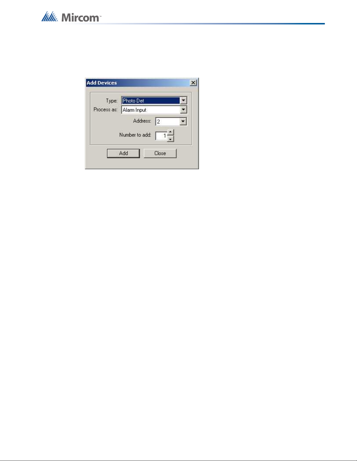
Appendix B: Using the Configurator
Add Device
This dialog is displayed in response to an Add Device command. Input zones are also treated
as a special kind of device and are added using the same dialog.
Type is the major device type, with choices such as Photo Det, Ion Det, Supv Opt Mod, etc.
The list of available process types in the Process as: combo box is adjusted according to the
device type.
In the Address field you can specify the address for the new device. This defaults to the lowest
available address for the chosen type. It takes into consideration that some types (Dual
Acclimate and Fire Phone) require two addresses, one at the chosen address and one at the
address + 100. An address appears in the list only if its paired address is also free.
You can specify how many devices to add by changing the Number to add value. The
configurator will attempt to allocate the devices sequentially, starting with the address you
selected. If there are insufficient sequential addresses you will be shown a message with three
options.
Click Yes to continue - The configurator will add the remaining devices where ever empty
addresses exist. The warning message will not appear again for this transaction.
Click No to stop - The block of sequential devices added so far will be committed. No further
devices will be added. A second message will tell you how many devices were successfully
added.
Cancel to abort - The entire transaction will be rolled back. No devices will have been added.
If at any time during the transaction there are no more available addresses, the entire
transaction is rolled back. No devices will have been added.
After the operation is complete the dialog remains open for re-use. The Address value is
adjusted to account for the devices just added.
If there are no available addresses for the chosen Type then the Add button is disabled. You
can select another type, or close the dialog.
The Close button dismisses the dialog.
61
Page 63

Appendix B: Using the Configurator
Add Display Adder
This dialog is displayed in response to an Add Display Adder command.
Select Adder Type - This control lists valid adder types.
The list only shows adder types that are allowed for the chosen annunciator.
Select Header - This control lists the headers (connectors) of the annunciator.
You may distribute display adders among the headers if an annunciator lists more than one.
Add - Press Add to insert an adder of the selected type. The Job Tree will be updated to show
the new adder. If the frame limit for the annunciator/header is exceeded an error message will
be displayed. Some Adders consume two or three frames.
The dialog remains open for adding more Display Adders. Press Close to dismiss the dialog.
Add Loop Controller
This dialog appears in response to an Add Loop Controller command.
62
Type - Choose the type of adder you want to add. Different products may list different options.
You can typically choose between an Addressable Loop and a Conventional.
Number to add - Enter the number of loop controllers you want to add.
Tag - Enter the optional tag to describe the loop controller.
Page 64
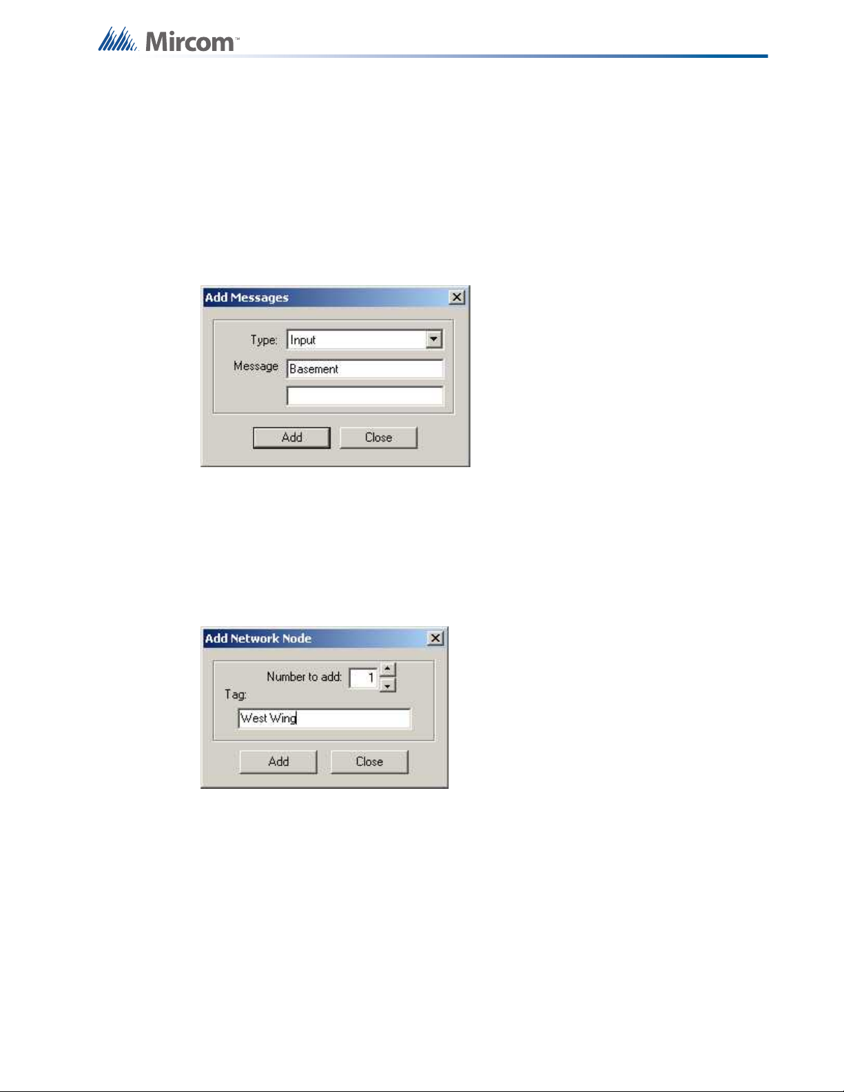
Appendix B: Using the Configurator
Click Add. Loop controllers will be added, up to the capacity of the target panel. If the capacity
would be exceeded a message is displayed and the operation is stopped. If a tag was
specified and more than one loop controller was added, they will all receive the same tag.
Tags can be edited in the Loop Controller Information view
Press Close to dismiss the dialog.
Add Message
This dialog is displayed in response to an Add Message command.
You can select from Input or Output Type. The Add button is disabled until you type at least
one character into the first row of the Message fields. You can type a maximum of 40
characters - 20 in each of the two fields.
Add Network Node
This dialog is displayed in response to an Add Network Node command.
Number to Add - Select the number of network nodes to add. Defaults to one.
Tag - the name or description for the new network node.
The next available Node Address will be allocated. This can be edited later.
Add UDACT
This dialog is displayed in response to an Add UDACT command.
63
Page 65

Appendix B: Using the Configurator
Report Format - Choose from Contact ID, SIA300 and SIA110. This is used only to set limits
on the UDACT Ref ranges.
Auto Assign - This option will automatically assign a UDACT group of the correct type for
every Input Zone and Output Circuit.
Advanced Panel Information Dialog
This dialog polls all the nodes and CPUs on the panel and checks their status against the
configuration.
The following information is displayed:
• Node - address
•Cpu No
• Type - CPU Type
• Version - current firmware version (n/a for RA1000)
• Language - language in firmware (standard messages/menu etc.)
• System Type - one of the following
• Compact Build
• Large Build
• HW Type - "base" or "Exp. Master" for the Large board
• HW Vers - currently always VX.X.X
• Status - one of the following
• Online
• Not responding
• Wrong type (configured as "xxxx" )
• Unconfigured CPU
• Firmware version mismatch.
• Address mismatch (configured as node xx).
• Offline trouble: xxx xxx
64
Audio Compose
Digitized messages are composed using WAV files. A sequence of commands describes how
the wave sounds are to be combined. For example, a message could be composed of a sound
that is played once, followed by sound that is repeated three times, and finally, a sound to
conclude the message.
Page 66

Appendix B: Using the Configurator
This dialog is displayed in response to an Audio Edit Message command.
There are two modes, regular (the default) and advanced.
In regular mode each clip or WAV file has an implicit loop that repeats the clip 'n' times. The
sequence can be concluded with a Repeat All command.
In advanced mode the user has complete control over four levels of nested loop commands
that can go around multiple clips.
Once a sequence uses advanced constructs it cannot revert to regular mode. A message is
considered advanced if:
• The sequence contains more than two levels of nested loops.
• An Audio Clip isn't followed immediately by a level 2 loop.
• The level 2 loop does not apply to the single audio clip.
• The outer most, level 1 loop doesn't apply to the whole message.
Audio Clips
This pane is common to Advanced and Regular mode. It lists all of the available clips, or WAV
files. Some are built in to the firmware of the Audio Controller, and are listed here to be used in
messages. Others were recorded by the user and imported.
Import When this button is pressed a standard file chooser is launched. Browse to the location
of a WAV file. This can be a file you have recorded, or any other suitable wave file.
They must be (.wav) files sampled at 11.025 KHz, 16-bit mono, ADPCM 4-bit. It is also
possible to use RAW (or PCM) in addition to ADPCM, but since this format is not compressed
it takes up more serial flash memory.
The file will copied to the database and given a unique name (a Microsoft GUID). The file will
receive another RIFF section, to include some naming and versioning information. Once a
WAV file has been imported, it will be listed in the Audio Clips and is available for use in
digitized messages.
Remove When this button is pressed the selected clip is removed from the database. The
deletion will not succeed if the clip is referenced by any message in any job on the database.
Once the clip is deleted it is no longer available for use in any job.
Audio Message
This pane lists the WAV files and commands that comprise a message.
You can give the message a name. Refer to this name when configuring a Digitized Message
switch, or for use as Alert or Evac, etc.
65
Page 67

Appendix B: Using the Configurator
Composition
Commands in the Composition list view can be added, deleted and moved up and down.
Select a WAV file in the Audio Clips pane and press the >> button to move it into the message.
It will initially have a count of 1. Edit the count to specify how many times the clip is to be
played. A value of 0 means repeat for ever. Repeat for ever should be used with care. If there
are following clips, they will never be played.
To repeat the entire sequence, insert a Repeat All command at the end of the list.
Commands in the Composition list view have the following columns.
Name Description
Command
Count
The command type. Either Audio Data (from the Audio Clips pane) or a
Loop Control command.
The number of times the clip is to be repeated. A count of zero means loop
for ever.
Wave The name of the wave file, as moved from the Audio Clips list.
Loop Control
66
In regular mode you specify the repeat count for a clip in its count field. You can use the >> key
to insert a Repeat All command. It must be the last command in the sequence.
Page 68

Appendix B: Using the Configurator
Standard Audio Example
This example plays an initial Your attention please two times. This is followed by a message
instructing occupants not to use the elevator, played only once. The entire sequence is
repeated 5 times.
Command Count Clip
Audio Data 2 Your Attention
Audio Data 1 Dont Use Elevator
Repeat All 5 -
Composition
Commands in the Composition list view can be added, deleted and moved up and down.
Select a WAV file in the Audio Clips pane and press the >> button to move it into the message.
Select a Loop Command and press the >> button to move it into the message. Loops can be
nested up to four deep. A Loop 1 command specifies an outer-most loop, etc.
Commands in the Composition list view have the following columns.
67
Page 69

Name Description
Appendix B: Using the Configurator
Seq
Command
Count
The command sequence number. Beginning with zero. Refer to this
number when specifying the base for a looping command
The command type. Either Audio Data (from the Audio Clips pane) or a
Loop Control command.
The number of times a loop is to be repeated (applies only to a Loop
Control command). A count of zero means loop for ever.
Wave The name of the wave file, as moved from the Audio Clips list.
This specifies the base command for a loop control. For example, a Loop
Loop Base
1 command in row 5 could specify Seq 1 as its base. This means that the
commands in rows 1,2,3 and 4 are repeated Count times. The user is
responsible for correct nesting of loops.
Loop Control
Select a Loop Control (level 1, 2, 3 or 4) to move into an Audio Message Composition. Loop 1
is used for the outer most loop. Loop 2 can be nested inside of a Loop 1,etc.
Advanced Audio Example
This example plays an initial Your attention please two times. This is followed by a message
instructing occupants not to use the elevator, played only once. Next, a whoop sound is played
3 times. The entire sequence is repeated 5 times.
Seq Command Count Clip Loop Base
0 Audio Data - Your Attention -
1 Loop 2 2 2 0
2 Audio Data - Dont Use Elevator -
3 Audio Data - Whoop -
4 Loop 2 3 3 3
5 Loop 1 5 5 0
68
Page 70

Appendix B: Using the Configurator
Audio Setup
This dialog is displayed in response to an Audio Setup command.
Alert 1, Alert 2, and Evac state options – press the ... (ellipsis) button to launch the Manage
Message Dialog to select which audio tone or digitized message to broadcast when the
system reaches that state. You can select an existing message or create a new one. On return
the selected message is assigned to the chosen Alert or Evac state. The controls associated
with Alert 2 will be disabled if the option "Sound pre-announce tone when paging" is enabled.
Manage Messages - also launches the Manage Message Dialog allowing you to add, delete or
edit messages. These message then become available for use here (for Alert 1, Alert2, etc.) or
to be assigned to a Digitized Message switch.
Sound pre-announce tone when paging – when enabled, a 900Hz pre-announce tone is
sounded (using the Alert 2 channel) for 2 seconds before the paging audio source is applied.
This special tone will un-silence speakers that are currently silenced.
Silence telephone buzzer when handset off hook – when enabled, the call-in buzzer on the
audio controller will be silenced when the local master handset is off hook.
69
Page 71

Backup Database
Backup database makes a copy of the Master Database.
Appendix B: Using the Configurator
By default the backup is made in the File folder specified in the User Preferences. The backup
file will have a name of the form YYYY-MM-DD.mdb.
After the Backup is complete, if the Keep Only Latest Versions After Backup option of User
Preferences is enabled, old versions of each job in your main database will be deleted,
retaining only the latest version of each job.
The backup can be used by the Restore Database command to recover all of the jobs in the
database. You can also use the Import command to recover selected jobs from a backup.
Backup your Master Database often and store a copy of the resulting file on a CD or other
media.
BDM Load
This dialog appears in response to the BDM Load command, after you have selected a
firmware archive.
70
Page 72

Appendix B: Using the Configurator
View Archive... - clicking this button opens the Firmware Archive Contents dialog, which lists
all of the files in the archive. There should be a file for every combination of System Type
(Compact and Large), Node Type and where appropriate, Language.
System Type - Choose the System Type to match the CPU you wish to load. Choose from
Compact and Large.
Select firmware to load - The list view shows all of the combinations of CPU Type and
language (for main CPUs and Annunciators). Select the row corresponding to the firmware to
be loaded.
Upgrade - click this button to start the firmware upgrade and follow the on screen instructions
Audio Choose Message
This dialog is displayed in response to Manage Message button on the Audio Setup dialog.
It lists all of the available messages.
Some standard messages and tones are built into the firmware and can be chosen for use as
Alert 1, Alert 2 or Evac. They can also be built into custom messages.
Custom messages are those that the user composed by combining recorded WAV files, built in
tones and looping commands.
Add - launches the Audio Compose Dialog where you can create a new message.
Edit - launches the Audio Compose Dialog where you can view or modify the selected custom
message.
Remove - deletes the selected message. Built in messages cannot be deleted.
71
Page 73

Appendix B: Using the Configurator
Compact Database
A database that has been the subject of many deletions and additions can become
fragmented and occupy more space than required. Compact Database executes a standard
MS-Access utility to recover the space and improve performance.
Note: This may take several minutes for a large database
Select Job to Compare
72
Primary Job - This field reminds you which job you have already established as primary job:
the base job against which the secondary job will be compared.
Select Secondary Job: Select Version - Use the combination of Job and Version to select the
secondary job. The job defaults to the same one you established as Primary. Normally you will
only need to choose a newer version of the same job. You are prevented from choosing the
same Job and Version for Primary and Secondary.
Just as when establishing the primary job, you can sort the list of secondary jobs by Job
Number, Description or Product.
Show Identical Items - Check this box if you want to see not only changes, but also those
items that stayed the same. Normally you will leave this un-checked. Differences are easier to
see and Print generates less output if identical items are not included.
Advanced Options - When you press this button the Advanced Options dialog is launched.
Here you can change some of the more advanced filtering options. They are normally all
checked by default and in most situations do not need to be changed.
Page 74

Appendix B: Using the Configurator
Advanced Compare Options
Modified - Check this box to include any item that has been modified. (Modified means that it
is the same adder, circuit, switch, etc. but some attribute has been changed.) This box is
checked by default. You would only un-check this box if you did not want to see items that
have been modified.
Present only in Secondary Job - Check this box to include items that are only present in the
secondary job. This means that Loop Adders, Annunciators, Display Adders, circuits, etc. that
were not on the base job will be included. This box is checked by default. You would only uncheck this box if you did not want to have new additions reported.
Present only in Primary Job - Check this box to include items that were only present in the
primary job. This means that that Loop Adders, Annunciators, Display Adders, circuits, etc that
were removed from the primary job will be included. This box is checked by default. You would
only un-check this box if you did not want to have deletions reported.
Note: Filtering of 'Present only in Secondary' and 'Present only in Primary' do not apply when
presenting the tree. The tree is shown in its entirety, regardless of these settings. The filtering
is only applied to the Device, Display Item and similar lists. It is intended to make it easy to see
what components have been physically added or removed from the job.
Correlations are not considered to be items in this context. If a correlation was added, then
that is effectively a modification to the item that received the correlation.
If you chose to check Present only in Secondary Job and/or Present only in Primary Job, but
you do not check Modified, then the circuits, etc. that have only had correlation changes will
not be included.
73
Page 75

Appendix B: Using the Configurator
Connect
This dialog is displayed in response to a Panel Connect command if the job has a Dialler
component.
Select a connection type
• Direct Serial - Select this option if you have connected a serial cable directly from the
serial port (or USB / UIMIA) of your computer to the fire alarm panel.
• Modem - Select this option if the fire alarm panel is capable of being programmed
remotely. The combo-box will list the modem(s) found on your computer.
• Telephone Number - Enter the phone number to which the fire alarm panel is
connected. The text field will show the last number you entered.
Create Job
• Enter a description for new job This name, which should be unique, will identify the job
throughout its lifetime. Note that in a multi-product environment the same job name
cannot be used for jobs of different products, even if you don't currently have access to
all possible products. An error message is displayed if the name is not unique. The error
message will help you identify duplicates that belong to other products or brands.
• Author The technician who is creating the new job. The default is automatically inserted
but can be overridden.
• Comments (Must be entered) Enter a comment. It can span multiple lines. This will
become part of the job's version history.
• Model Choose the Panel Model for your new job.
• Select Job Template After you have selected a model the list view will show only
templates jobs for the that model. The list view has the following columns.
• Agency There are two copies of most template jobs: one for ULI and one for
ULC. The new job will be pre-configured for the chosen agency, but can be
subsequently changed.
• Description A short description of the template job. For a given combination of
Product, Agency, System Type and Language there may be more than one
template job. Each is pre-configured with different features. The Description
field summarizes the features.
74
Page 76

Appendix B: Using the Configurator
• Language If the panel firmware supports it, there may be template jobs for more
than one language. e.g. English or French. For panels with multiple CPUs, this
is the language of the Main CPU. The firmware must match otherwise the job
cannot be sent to the panel.
• Copy current job data As an alternative to choosing a standard template, check this box
to make a copy of the current job (which is presently open in the configurator). In this
case the Panel Model and Job Template controls are disabled.
Note: This dialog is also shown when Get Job is used to retrieve a job from the panel and no
previous version of the job is stored on the database. The same dialog is used if the job name
on the panel and the database are the same, but the Product is different. You will be prompted
for a new, unique name. In these cases the Panel Model, Job Template and Copy current job
data controls are disabled.
Display Structure
This utility allows you to view the contents of a panel data structure. You have the option of
continually retrieving and displaying the same structure at a refresh rate you specify. You can
also log the results to a file.
To display a structure proceed as follows.
• Connect to the panel and click Display Structure under the Tools menu (you must have
selected Show Tools Menu under preferences). The following dialog appears.
75
Page 77

Appendix B: Using the Configurator
• Choose the Node and CPU.
• Choose the Structure on that CPU. Loop structures are qualified with a loop number.
e.g. gLCUPollData - Loop 2.
• Choose the entry (for Poll Data there is one entry per device, other structures may be
organised differently).
• Choose how many entries to display. The maximum is adjusted automatically to
compensate for the selected start entry. Note: The actual entries on the panel may be
less than the maximum. If you choose a start entry higher than the actual number of
entries on the panel you will get an error message. If you choose a number of entries
greater than those actually on the panel, you will receive only those that are present.
• You can get a "one shot" display by pressing Refresh.
• To run continuously, select a refresh rate and press Start.
• To log to file check the Log To File box and specify a destination file.
You can adjust the refresh rate, the start entry and the number of entries while the display is
running. They will take effect after the next interval has expired.
To view a different structure you must first press stop.
76
Page 78

Appendix B: Using the Configurator
Edit Job
This command toggles the edit lock on a job.
A newly created job or a new version of an existing job can be edited immediately.
An existing job, freshly opened can be locked at two levels. A job that has never been loaded
to a panel is locked against accidental change. The locking of such a job can be simply
toggled by using the Edit Job menu option. If a job is locked and the user enters keystrokes on
any of the editable forms or lists, a dialog will be shown, asking the you to confirm your intent
to edit the job.
If you answer Yes, the job is unlocked (as if the menu option had been selected). The GUI's list
and forms then allow editing, with changes taking immediate effect. If you answer No, all
subsequent keystrokes (or mouse clicks) on that form or list are ignored.
A job that has been loaded to the panel has a harder level of locking. It is intended to prevent
the database and panel copies of the job diverging. If the user attempts to toggle the lock from
on to off, then the following message appears.
If you choose to proceed, the job is unlocked. If an attempt is made to edit the same job on
one of its lists or forms, a similar dialog is shown but without the option to unlock the job.
Once a hard locked job has been unlocked, it can only be toggled between soft locked and
unlocked.
Export Job
This command exports the current job in one of two formats.
The user is presented with a File Chooser dialog.
77
Page 79

Appendix B: Using the Configurator
If Type MDB is chosen, a Microsoft Access database containing a single job is produced.
If Type Job Archive File (fx2Job - serialized data structures) is chosen, then a compact archive
file is produced.
By default, the file is given a name “Jobnn-vv” where nn is the job number and vv is the
version. You can change the name to make it easier to identify the job.
Either of these formats can be the subject of a Job Import.
Export is used to exchange a single job, for example between technicians. The fx2job format
results in a very small file, suitable for electronic transmission.
Shortcut Keys: Ctrl-E
78
Page 80

Firmware Archive Contents
Appendix B: Using the Configurator
This dialog is launched from the Upgrade Firmware dialog.
It lists all of the files in the archive.
Type- Either Firmware (the firmware image) of Dnld Program (a small boot strap program sent
by Upgrade Firmware).
System Type - For products with more than one system type. For example Compact and
Large.
NodeType - The Node or CPU Type for which the firmware file is intended.
Language - For Annunciators or Base Panels, the language of the built in system messages.
HW Type -
HW Vers -
About Dialog
Displays the copyright notice and version number of your copy of the Configuration Utility.
79
Page 81

Appendix B: Using the Configurator
Holidays
This dialog allows you to add and remove holiday definitions for use when a panel is
configured with the After Hours option.
Compose a new holiday definition in the YYYY MM DD edit boxes and press Add Holiday. You
can specify recurring holidays by using wild cards.
Enter 9999 for the year to specify that the holiday happens every year.
• e.g. 9999 01 01 for New Years Day.
Enter 99 for a month or day to specify a recurring holiday.
• e.g. 9999 99 01 to specify that the first of every month is a holiday.
• e.g. 9999 07 99 to specify that the site is shut down for the whole of July for summer
vacations.
By default the holiday has a Duration of 1 day. Change this to specify a longer holiday.
• e.g 9999-12-25 2 to specify a two day break beginning on December 25th.
Note: The program prevents you from entering duplicate holidays, but does not check for
"nested" holidays.
As holidays are added or removed, the list on the "parent" form is maintained to be in
agreement. An error message is displayed if the limit for the total number of holidays would be
exceeded.
80
Page 82

Appendix B: Using the Configurator
To remove a holiday, select it in the lower Holidays defined list and press Delete Selected
Holiday
Press Close to return to the Job Details form.
Import Job
This command imports a selected job/version from an external database or serialized job
archive as created by the export or Backup Database commands and converts the job to the
current version if necessary. The user chooses the type (MDB or Serialized Archive) and
location of the file to read. The location defaults to the Job File folder specified in User
Preferences
If the selected type is MDB, then the Microsoft Access database (usually a database that
resulted from a Backup Database) is opened. A list view, similar to the Open Job dialog,
displays jobs contained in the database. The list will be restricted to the Products for which the
user is authorized.
The chosen job is read and copied to the current database using logic common to Restore
Database. If the version of the source database is not too old (no forward conversion is
possible) and is not younger than the current database, then any necessary conversion is
performed. If the database version is not compatible, an error is displayed.
If the selected type is fx2job (a serialized archive, usually the result of Export) then the Jobs
found in the archive's index are listed. The data structures are de-serialized and treated very
much as if they had been downloaded from a panel. The program adjusts older versions of
data structures to the current standard, extracts the data and stores the job on the database.
If the same job (identified by its name) is already on the database, then the next highest
version is assigned to the job.
If a job with the same name is not on the database, then a new job is created.
81
Page 83

Appendix B: Using the Configurator
Logic Editor Dialog
Displays in response to the Edit button on the Advanced Logic correlation tab.
Using this dialog the user can compose an equation to be applied to a local, dummy input
zone. The input zone is then correlated, using regular IO corrs, to the output which is
ultimately the object of the equation. This is done by specifying any number of local and
remote inputs zones, local input circuits, timers and intervals (operands) and boolean
expressions (operators).
When the result of the equation, evaluating the TRUE/FALSE state of all inputs, is TRUE the
associated output will be energized. The equation overrides any other Input/Output
correlations.
WARNING: Applying an equation directly to an output bypasses all of the regular input to
output correlation processing. That is - coded inputs are not processed, etc. Use of a dummy
input zone as the intermediary is the preferred method.
The operands recognized by the equation builder are
•AND
•OR
•NOT
•EQU
• ANY x OF( inputs )
Examples:
Turn on a relay if a smoke detector in the lobby is in alarm, but not if the smoke detector in the
elevator machine room is detecting smoke.
= 01-00-L2-SM-001 AND NOT 01-00-L2-SM-002
Release halon in a semiconductor clean room only if three of the 10 verified alarms in the area
are active.
= ANY 3 OF ( 01-00-L2-SM-001 , 01-00-L2-SM-002 , 01-00-L2-SM-003 , 01-00-L2-SM-004 ,
01-00-L2-SM-005 , 01-00-L2-SM-006 , 01-00-L2-SM-007 , 01-00-L2-SM-008 , 01-00-L2-SM009 , 01-00-L2-SM-010 , 01-00-L2-SM-011 )
Associate an equation with a dummy input and then reference that input in several equations
attached to outputs. In this example zone 3 will be TRUE if smoke detectors 5, 6 and 7 are
active. Zone 3 is then re-used in the equations for four different relays. Relay 1 will be
energized if the equation for zone 3 is TRUE and smoke detector 8 is not active. The simplifies
the relays' equations, which would otherwise all have to include zone 3's equation.
82
// Common to activation of relay #1,2,3,4.
01-00-**-IZ-003 = 01-00-L0-SM-005 AND 01-00-L0-SM-006 AND 01-00-L0-SM-007
// First relay
01-00-L1-RL-001 = 01-00-01-00-**-IZ-003 AND NOT 01-00-L0-SM-008
// 2nd relay
01-00-L1-RL-002 = 01-00-01-00-**-IZ-003 AND NOT 01-00-L0-SM-009
Page 84

Appendix B: Using the Configurator
// 3rd relay
01-00-L1-RL-003 = 01-00-01-00-**-IZ-003 AND NOT 01-00-L0-SM-010
// 4th relay
01-00-L1-RL-004 = 01-00-01-00-**-IZ-003 AND NOT 01-00-L0-SM-011
The left hand pane lists all of the elligible inputs. These are currently limited to
• Local input circuits
• Local input zones
• Remote input zones
• Custom Intervals
• Custom Timers
• Switches
The columns of the list view include an ID. This is a short hand form of the circuit's location. It
is contructed from the input's Node, CPU, loop (if any), a two character code indicating the
type and the address or number of the input.
The ID is intended to assist the user in recognizing the input when it appears in the final
equation.
The remaining columns are the Node, CPU and Tag of the input.
The circuit, timer or switch can be simply tested for TRUE and FALSE, or a particular Device
Status can be tested. If a status is selected in the Device Status drop down, it will be appended
in the form of :x to the device ID when it is inserted into the equation. Each one applies a
different mask to the device's state.
The right hand pane shows the current equation, if any, on entry or the equation under
construction.
Although the user can type into the right hand pane, it is recommnended that they insert
operands and operators using the controls.
To enter an input, double click it in the left hand list or select it and press the insert button “>”.
The ID of the input will be inserted in the equation at the current cursor location.
To enter an operator, click one of the operator buttons.
To enter multiple inputs separated by commas, select them in the list by using the mouse in
combination with the Ctrl key or Shift key. Press the insert button. If an operation is to be
applied on the inputs, such as “Ckt1 OR Ckt2 OR …”, select the inputs from the list and then
press the operator button. The complete expression, enclosed with parentheses, will be
inserted into the equation.
The EQU operand is used in combination with a System Define (a constant). It tests a device's
state and produces a TRUE|FALSE result. You may have to apply a device mask to isolate the
states you want to test.
e.g. **-**-**-TM-016 EQU TIMER_RUNNING Test for a timer running.
e.g. 01-00-02-IN-003:L ALARM_LEVEL2 Test an input's alarm level
Note: not all Sys Defs can be applied to all circuit types. The user is repsonsible for choosing a
valid combination of device mask and Sys Def.
83
Page 85
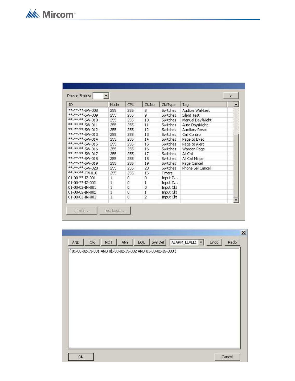
Appendix B: Using the Configurator
The Sys Def button inserts a named constant into the equation. You can select a named
System Def in the drop down list before pressing the button.
The OK button causes the equation to be parsed and verified. If there are syntax errors an
error message will indicate the location of the error in the string.
Press the cancel button to dismiss the dialog without making any changes.
84
Page 86

Appendix B: Using the Configurator
New Job Version Information
Displays in response to the New Version command
Also when a job is uploaded from the panel and a job with the same name already exists on
the database.
Default user spec'd in user preferences (may be changed).
Note: A Comment MUST be entered for the Version history when you create a new Version of
a Job.
Open Job
This dialog, which appears in response to the Open Job command, allows the user to select a
job and job-version in the database and open it in the user interface.
The Select Job list view shows all of the jobs on the database. By clicking on the column
heading you can sort the jobs by
• Job Number
• Job Description
• Product (where more than one product is supported)
The Select Version list view shows all of the versions of the selected job. This includes the
date and a description.
Click OK after you have selected a job and version.
85
Page 87

Appendix B: Using the Configurator
Panel Information Dialog
Displays in response to the Panel Information command.
This dialog displays a summary of panel and the configurator information, with options to view
more detail. The information includes:
• The Product Version
• Name and Version of the job currently loaded on the panel.
• Model (deduced from Product, System (build) Type and Hardware Features).
• The Date it was sent
• The ESD and Tech who sent / owns the job. (For products secured with a key)
• Security Key SIN. (For products secured with a key)
• FXConfig Version
• Date and Time Last Changed
• Number of times auto config'd.
• The Panel Time.
An Advanced button launches Advanced Panel Info which retrieves and displays the Type,
Product Version, Language, on line status, etc. of all Nodes and their CPUS.
86
An Update button allows the panel time to be corrected/updated from the configurator for
those products that support the feature.
Page 88

Appendix B: Using the Configurator
Paste Special
This dialog appears in response to a Paste Special when pasting circuits, conventional adders
or entire loops.
The text summarizes what is being pasted and its destination.
e.g Copying Node 1, or Pasting 3 devices to loop 2.
Number of copies - specifies the number of copies to make. The paste operation will attempt
to make the specified number of copies. If the capacity of the destination is exceeded a
message will be displayed to inform the user how many were successfully made.
Copy I/O correlations - If this box is checked the copied device(s) will have the same I/O
correlations as the original.
87
Page 89

Appendix B: Using the Configurator
Copy display correlations - If this box is checked the copied device(s) will have the same
display correlations as the original.
Retain Address - Check this box to retain the same addresses on the copied devices. A
message will inform the user if this is not possible. Retain Address can fail if the destination
loop controller does not have sufficient free addresses. Retain Address will always fail if the
source and destination are the same loop.
Paste Special
This dialog appears in response to a Paste Special when pasting display items, display adders
or entire annunciators.
The text summarizes what is being pasted and its destination.
e.g Copying Node 33, or Pasting 3 display items to frame 0.
• Number of copies - specifies the number of copies to make. The paste operation will
attempt to make the specified number of copies. If the capacity of the destination is
exceeded a message will be displayed to inform the user how many were successfully
made.
• Make New Copy - Choose this option to make an unrelated replica of the source.
• Copy I/O Correlations - If this option is checked, the new display item(s) will be
correlated to the same circuits and devices as the source.
• Make Reference Copy - Choose this option to make a reference copy of the source.
A regular copy is defined as follows.
• The LEDs and/or switches are copied and become separate entities from the orignal
LEDs or switches.
• Common Control Status LEDS are an exception - all similar types operate in parallel.
e.g. A copied and pasted Signal Silence would retain the internal LED Grp of the source.
• All attributes (tags, flags, etc.) are replicated.
• If IO Corrs is checked, then these too are assigned to the new copy. This is a "deep"
copy.
88
• If IO Corrs is not checked they are not copied. This is the "shallow" copy.
Page 90

Appendix B: Using the Configurator
A Reference copy is defined as follows.
• New LEDs and switches are defined, but they are linked closely to the original source.
• If any 3 POSITION SLIDE SWITCH is encountered while attempting a "Reference
Copy" of individual items, a complete adder or an entire annunciator, an error message
is displayed and a roll back of the operation occurs.
• Both the new copy and the source (and any subsequent reference copies) will be
marked with an asterisk to warn the user that the items are 'linked" or cross referenced.
A change to one (e.g addition of CORRS) affects the others.
Print Dialog
When you initiate either Print or Print preview, the following dialog is displayed.
Print Range - You can specify the range or scope of the print job using these controls
Complete Job - Regardless of what item in the Job Tree you currently have selected, the
complete job will be printed. The print program will iterate through the network nodes. This
process continues in a depth first manner, until the entire job has been traversed and printed.
Each major item of the tree is started on a new page.
Current Item - If you choose this option, the print job is restricted to details of the tree item or
job component that you currently have selected in the Job Tree. No details of contained loops,
etc. are printed.
Current Item and Sub Items - this option prints details of the currently selected tree item and all
of its sub-items (and those items' sub-items, if any).
Outputs with Input Corrs - If this box is checked, then the Inputs correlated to Output circuits
are printed in addition to the regular print. This is done for any relevant tree items / loops that
are included in the scope of the print job.
Inputs with Output Corrs - If this check box is checked, then the Outputs correlated to Input
circuits are printed. Status correlations are included with this option. This is done for any tree
items / loops that are included in the scope of the print job.
89
Page 91

Appendix B: Using the Configurator
Display Corrs - If this check box is checked, then the Display correlations are printed. This is
done for any relevant tree items / loops that are included in the scope of the print job.
General Note - Correlations
If a tree item has no correlations, then it is skipped entirely by the print program. If a tree item
has correlations, then a header is printed for every "correlated from" device. Beneath it, and
tabbed, are all of the devices correlated to it. If it has none, the major header is still printed.
Setup - This button launches the standard Windows © printer setup dialog. You may choose a
printer other than the default, or select a different paper size. The print program is designed to
fit all information on Letter sized paper (8 ½ by 11) in portrait orientation. You may also choose
Legal sized paper (8 ½ by 14). The print program will take advantage of the longer paper and
fit more devices on one page for list views and correlations. If you choose smaller paper the
font will be scaled down accordingly (within practical limits).
Pages - this check box is only available when performing a print. It is disabled for print
preview.
During preparation of a print preview or a print you will notice that the program makes one first
pass through the tree items and loops that are in scope. It does this to calculate the page
count. However, the program cannot insert the Max Page Number into the dialog because it is
not known at that time.
If you need to repeat part of a print job (e.g. because the printer jammed part way through a
job), then you must note the start page and the end page - up to the maximum number of
calculated pages - and enter them in the From and To fields.
Generally, you can more easily control which portions of a job you wish to have printed by
selecting an item in the tree and printing only that item.
Print Setup
Launch the standard Windows Print Setup dialog to specify the printer, paper size and
orientation, etc.
90
Page 92
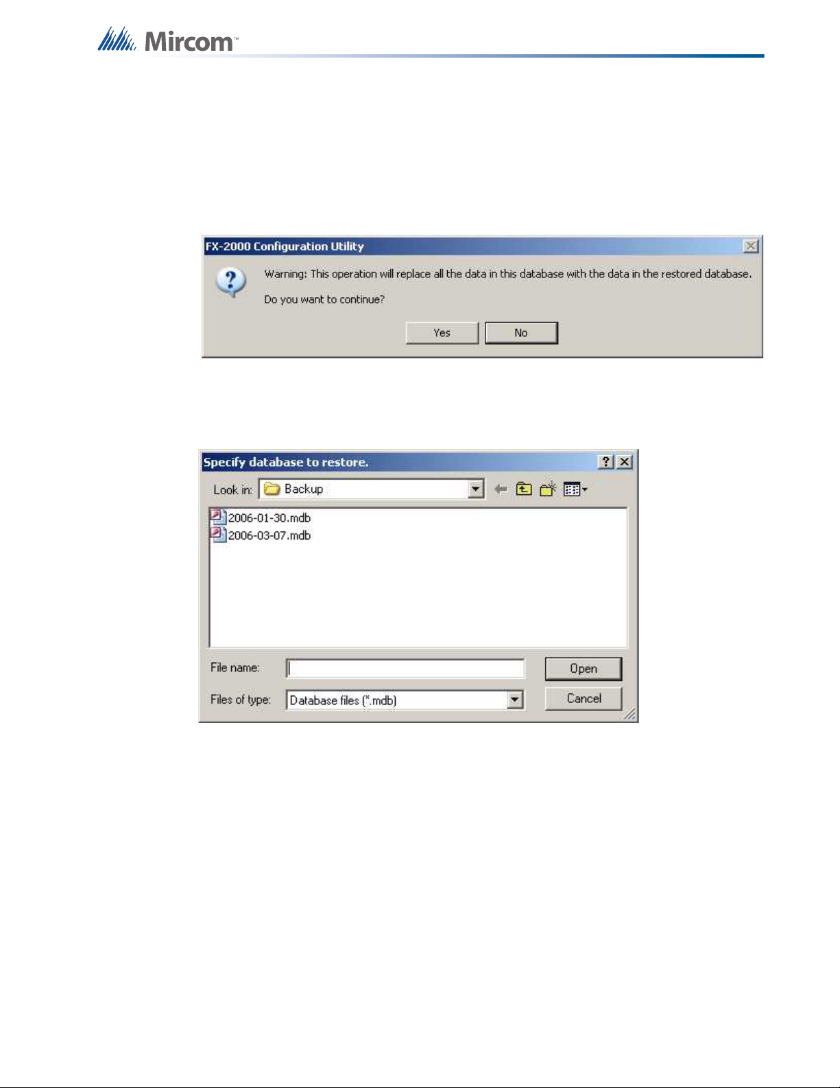
Appendix B: Using the Configurator
Restore Database
Restore database reads a database file and imports every job found there, after first deleting
all of the jobs in the current database.
Warning: When you restore from an older backup you will lose any changes that have been
made since the time of the backup.
If you choose to continue the following dialog will open. By default backups are stored in the
Backup File folder specified in the User Preferences. The backup file will have a name of the
form YYYY-MM-DD.mdb.
The backup database could have been produced by an older version of the configuration tool,
in which case all necessary conversion is performed. Conversion is sometimes necessary
when a new version of the configuration tool is released. The install program will make a
backup and instruct you to run Restore Database to convert all of your jobs.
Security Key Logon
This dialog appears if the Security Key is present when the configurator is first started. It also
appears if the key is inserted at a later time while the configurator is running.
91
Page 93

Appendix B: Using the Configurator
When the dialog appears, enter your PIN and press OK. If the PIN is accepted all future,
privileged operations will proceed with no further prompting as long as the key is still inserted.
If the user dismisses the dialog (by pressing escape) or removes the key, then any attemp to
perform a secure operation will fail with the message
You need a valid security key to perform this operation.
You must reinsert the key and enter the correct PIN. Also see: Security Key Information
Upgrade Firmware
This dialog appears in response to the Upgrade Firmware command, after you have selected
a firmware archive.
92
View Archive... - clicking this button opens the Firmware Archive Contents dialog, which lists
all of the files in the archive. There should be a file for every combination of System Type
(Compact and Large), Node Type and where appropriate, Language.
View Panel Info... - clicking this button opens the Advanced Panel Information dialog, which
lists all of the CPUs actually present (Online or Not Responding) on the panel.
Page 94

Appendix B: Using the Configurator
The configurator interrogates the panel to which it is connected and lists all of the CPUs
actually present and on-line. The list view shows the CPU Number and Type and other
information, including the current language for main CPUs and Annunciators.
By clicking in the Language field you can select a different language. The CPU will be loaded
with firmware for the chosen language, assuming the firmware archive contains the file.
Selected CPUs Only - check this box and select the CPUs you wish to upgrade. You can
select multiple rows by holding down the Ctrl key and right clicking anywhere in the row. If this
box is not checked all of the CPUs will be upgraded.
Upgrade - click this button to start the firmware upgrade
User Preferences
This dialog is displayed in response to the File menu's User Preferences command.
• User Name - used for the Author of all new jobs and job versions
• Serial Port - designates which COM port (or USB pseudo COM port) the configurator will
use to connect to the panel.
• Security Key port - Specifies the port where a WiBu key will be inserted. The drop down
list shows the ports that have been registered by the WiBu software. The list will include
LPTn if the computer has a printer port. The list may include USB, but only if a USB
WiBu key has been inserted and the New Hardware Wizard has been run to install the
required drivers. Further, a USB key must have been plugged in since the last restart of
the computer, else USB will not appear as an option. If neither LPT nor USB are
registered, a warning will be issued. The user cannot perform any privileged operations
until a valid choice has been made. If only LPT is registered a warning will be issued
since most computers would be expected to use USB for the security key.
• BDM Port - designates which parallel port the Background Debugging Module will use
(for those products that support this interface).
• Database Folder - specifies where the main configurator.mdb database file resides.
Usually the folder where the configurator is installed.
93
Page 95

Appendix B: Using the Configurator
• Backup Folder - specifies where backup database files are written to and restored from.
• Job Edit Folder - specifies where individual job files are extracted to/imported from.
• Job Build Folder - specifies where the 'C' file output files are written by Job Validate and
other trace or debug facilities.
• Show Tools Menu - display or hide an additional Tools menu. This menu contains trace
and debug facilities and some features that Technical Support may require a user to turn
on to gather diagnostic information.
• Keep Only Latest Versions After Backup - if enabled, only the latest versions of all jobs
will be kept after a successful Backup Database command, all older versions are
removed from the current database.
• Show Advanced Features - if disabled, some of the more advanced features are hidden.
These values are stored in the registry (per configurator version) so that a returning user
operates in the same folders, etc.
On the first execution of the configurator this dialog is popped up automatically to establish
these values.
Update Panel Time
This dialog can be displayed from the Panel Information Dialog.
It is also displayed when the configuration tool detects that the panel time is significantly
different from the PC time.
New Time: defaults to the current PC time. Adjust this time if necesary and presss OK to
update the panel time
Version History
This dialog appears in response to the Version History command.
94
The version history of the current job is displayed in list form, beginning with the most recent
version.
Page 96

Appendix B: Using the Configurator
Number - The version number. Each time a new version is created, either with the New
Version command or by getting a job from the panel or an archive, a new version number is
allocated.
Date - The date and time the version was created.
Changed by - The user who created the version.
Description - The description, as entered when the new job version was created.
Type - Uploaded- the new job version was a result of a Get Job. New Job - the user created a
new version manually.
Status - Either Locked- the job has been sent to the panel and is locked against editing or
Editable.
Audio Controller Details
This form view appears in the top, right pane when an Audio Controller item is selected in the
Job Tree view.
• Tag: Enter a desciption for the audio controller. This will appear in the Job Tree view.
• CPU Number: Enter the CPU address for the audio controller. A drop down combo box
lists the available addresses.
• QMB-5000 in Bin 0: check this box if the amplifier bin arrangement is that of the QMB-
5000. The legacy QMB-5000 has seven amplifier slots. If the box is not checked the
QMB-5000N is assumed. It has only four amplifier slots. During conversion from QMB5000N to QMB-5000 any existing amplifiers in expansion bins are re-arranged to first fill
95
Page 97

Appendix B: Using the Configurator
the additional bins of the QMB-5000. During conversion from QMB-5000 to QMB-5000N
any existing amplifiers in the base unit's extra slots are moved to the expansion bins.
• QBC-5000 Charger in use: check this box if the amplifier battery charger is a legacy
QBC-5000. Leave the box un-checked if a QBC-5000N charger is in use. Selecting the
wrong charger can affect battery supervision and charging.
• Silenceable Speakers: check this box if the speakers connected to the controller can be
silenced.
• Microphone present: check this box if there is a microphone installed on this audio
controller. If there are two or more microphones on the job, then one must be flagged as
Master and the control enable required option must be checked on every node with a
microphone.
• Master microphone: check this box if there is a microphone installed on this audio
controller and it is to be designated as the Master. If there are two or microphones on
the job, then one (and only one) must be designated as master.
• Control Enable required for mic press to talk: if this box is checked the operator must
enable use of the microphone (through the menu or a key switch). This option must be
checked if there is a microphone present on this node, and there is at least one other
microphone on another audio controller on the job.
• Master Handset: If you specify a master handset, the first telephone line is used for that
purpose. The line will be hidden from view and cannot be used.
• If line 0 is currently in use (either as a voice line serving addressable phone modules, or
as a conventional phone) and you check this box you will be asked for confirmation
before the line is removed.
• If you remove the master handset, line 0 will become available for use. If there is a
correlation from a telephone selector switch to Call Control at this network node, you will
be asked for confirmation before the master handset is removed.
• Call in buzzer: Select to enable the call in buzzer
• Control Enable required for master handset: if this box is checked the operator must
enable use of the master handset (through the menu or a key switch Control Enable).
System/Node/CPU Status
This list view appears in the top, right pane when either the Common System Status, Node &
CPU Status or Annun Status item is selected in the Job Tree.
System Statuses are pseudo inputs that can be correlated to outputs. For example:
• Correlate a signal circuit to operate as a power supply. (using Init Done).
• Customize the Fire Drill operation.
• Correlate a relay to operate on Reset Command (using Sys Reset)
System Statuses are can also be correlated to LEDs.
System statuses can have three different scopes.
• Common System Status - as the name suggests, their scope is system wide. Common
Alarm,Fire Drill and Signals active are some examples. They need no further
qualification.
• Node Status - Node Active and AC On are examples of Node status. The list view
appears once for each network node on the system. When you choose one and
96
Page 98

Appendix B: Using the Configurator
correlate to it, you are specifying, for example, the AC On status of the selected Node.
The Scope column specifies the Node of the status.
• CPU Status - These fall into two categories.
• The list view containing the special Annunciator Statuses, Control Enabled and
its complement, appears in the job tree for every CPU that has a LCD (Main
Display and LCD Annunciators).
• The list view containing the other CPU statuses appears in the job tree for each
network node and is combined with the Node Statuses. These CPU Statuses
are assumed to be associated with the main CPU of the Node.
The Scope column specifies the Node and CPU of the status. You must have defined a
suitable LED to accept the correlation from the Node or Node/CPU specific status.
Some columns containing advanced or internal information are normally hidden. They are
listed as Visible / No in the following table.
Name Visible Description
Item No The database status number. For debugging purposes.
F/W Status Yes The firmware status number.
Node No The Node Number (only applicable for Node and CPU statuses).
CPU No The CPU Number (only applicable for CPU statuses).
Scope Yes
Either Common for system wide statuses or the Node name, or
Node CPU combination of the status.
Status Yes A short description of the status.
F1 Yes Flag field: NS for Non-Silenceable or blank.
97
Page 99

Appendix B: Using the Configurator
Name Visible Description
Flag field: GA for General Alarm or blank.
The GA flag is only applicable in a Two Stage system. The
outputs correlated to a Common System Status with the GA flag
set will sound at the General Alarm (aka Evac) rate, else they
sound at the Alert Rate.
F2 Yes
In a single stage system, where all outputs correlated to alarm
inputs sound at the Evac rate, the column is hidden.
The actual tone sequences or digitized messages to be used for
Evac and Alert are specified on the Job Details and Audio Setup
dialogs.
Some System Statuses can also be correlated to a switch. Examples are Signal Silence, Fire
Drill, Aux Disc, Total Evacuation. When one of these items is selected the Switches tab will
appear on the associated Correlation View. This will show any display adder switches that
have been correlated to the System Status. Note however, that this does not include remote
switches (input circuits or devices of type Input Module that are assigned to a Common
System Status).
When correlating from a Common System Status to display items and switches, the behaviour
is different from correlating to Signals and Relays. The Add Correlations dialog will only show
unassigned LEDs and Switches as available to be correlated. Correlating the Common
System Status to a display item changes the display item's type and assignment.
Correlations
Most of the primary list views (shown in the top right pane) are used in combination with a
correlation view in the bottom right pane. The correlation view is a tabbed pane. Each tab
shows a different category of circuit, display LED, etc.
98
Output Circuit Correlations
If the currently selected circuit(s) is/are outputs then the correlation view typically has tabs for:
•Alarm Zones
• Supv Zones
Page 100

Appendix B: Using the Configurator
•Trouble Zones
• Monitor Zones
• Display Points (Output Zones and Bypass LEDs etc.).
Input Circuit Correlations
If the currently selected circuit(s) is/are inputs then the correlation view has a tab for Input
Zones only. Input Circuits must be combined into input zones before they can be correlated to
outputs or LEDs, etc.
When the user selects Add Correlations a non-modal dialog is used to display the circuits and
display items that are eligible to be correlated to the selected items in the top, right pane. It has
the same set of tabs as the correlation view. It is kept synchronized with the correlation view: if
a certain tab category is selected on one, its counterpart is automatically selected on the other.
As correlations are added to the current set, they are removed from the available set.
If multiple items are selected in the top pane, then the correlations view will only show those
correlations that are common to all of them. This means the set of displayed correlations can
shrink to the empty set. If the user selects a mix of input and outputs no correlations can be
shown.
Advanced Logic
Individual outputs ciruits or inputs zones can also be assigned an equation. If only one of
these items is selected in the top pane, an Advanced Logic tabbed pane appears. If an
advanced logic equation has been composed the text string will appear on the tab. To create a
new equation or edit an existing one, use the Edit... button to launch the Advanced Logic
Editor.
If an equation is associated with an output there should be no other IO correlations driving the
output. If an equation is associated with an input zone there should be no input circuits
correlated to the input zone.
Interval List View
This list view appears in the top, right pane when the Custom Interval item is selected in the
Job Tree view.
Custom intervals complement the system intervals (HOLIDAYS, WEEKEND, EVENING, etc.).
Unlike system intervals, which can have begin and end calendar dates, custom intervals are
only comprised of start and end times (HH:MM) and optionally a day of the week. Thus, they
can be used to turn on a dedicated air handling system once a week for testing for example, or
to reduce sensor sensitivity during certain hours of the day.
Custom intervals can be referenced by equations. If an interval appears on the right hand side
of an equation controlling an output or an input zone, it can be tested for TRUE (current
system time is within the bounds of the interval) to affect the result of the equation.
A custom interval has only one time range. If you need to test for multiple ranges, you must
create multiple intervals and OR them using an equation.
For example:
06:00 to 09:00 "Kitchen in use - breakfast."
11:00 to 13:00 "Kitchen in use - lunch."
99
 Loading...