

Mircom FA-300, FA-300-6DDR, FA-300-6DR, FA-301-12DDR, FA-300-6DDR-CG Installation And Operation Manual
Page 1
FA-300 Series
LCD Fire Alarm Control Panel
Installation and Operation Manual
LT-906 Rev. 10.2
June 2017
Page 2

Page 3

Table of Contents
1.0 Industry Canada and FCC Notice 9
1.1 Notice for all FA-300 Series Built-In UDACTs Sold in Canada ...................................... 9
2.0 Introduction 11
2.1 Overall Features ............................................................................................................ 11
3.0 Conventions 12
3.1 Circuits ........................................................................................................................... 12
3.2 Zone ............................................................................................................................... 12
3.3 Events ............................................................................................................................ 12
3.4 Wiring Styles .................................................................................................................. 12
4.0 System Components 13
4.1 Main Fire Control Panel ................................................................................................. 13
4.2 Relay Module: 12 Relays ............................................................................................... 14
4.3 Relay Modules: Six Relays ............................................................................................ 14
4.4 Polarity reversal/city tie .................................................................................................. 14
4.5 Remote Annunciator ...................................................................................................... 14
4.6 Smart Relay Module ...................................................................................................... 15
4.7 Input Class A converter: Six Circuits .............................................................................. 15
4.8 Output Class A converter: Four Circuits ........................................................................ 15
4.9 Output Class A converter: Two Circuits ......................................................................... 15
4.10 Active end-of-line resistor .............................................................................................. 16
4.11 RAM-216 Remote Annunciator ...................................................................................... 16
4.12 Additional Fire Alarm System Accessories .................................................................... 16
5.0 Mechanical Installation 17
5.1 Installing the Enclosure .................................................................................................. 17
5.2 BBX-1024DS and BBX-1024DSR Mechanical Installation ............................................ 19
5.3 Installing the Adder Modules .......................................................................................... 20
6.0 Connections, DIP Switches, and Jumpers 22
6.1 Main Fire Alarm Board ................................................................................................... 22
6.2 ICAC-306 Input Class A Converter Adder Module ......................................................... 24
6.3 OCAC-304/302 Output Class A Converter Adder Module ............................................. 25
6.4 Relay Adder Modules (Models RM-312 and RM-306) ................................................... 25
3
Page 4

Table of Contents
6.5 RM-306 Six Relay Adder Module .................................................................................. 27
6.6 Polarity Reversal and City Tie Module (Model PR-300) ................................................ 27
7.0 Field wiring 29
7.1 Main Fire Alarm Board Field Wiring ............................................................................... 29
7.2 Relay Adder Module Wiring ........................................................................................... 32
7.3 Connecting to a 3G4010CF Interface Device ................................................................ 34
7.4 Polarity Reversal and City Tie Module (PR-300) Wiring ................................................ 35
7.5 Power supply connection ............................................................................................... 36
7.6 Wiring Tables and Information ....................................................................................... 37
7.7 Supervised Auxiliary Power (regulated) ......................................................................... 38
7.8 Auxiliary Power (unregulated) ........................................................................................ 38
8.0 Turning on the Panel 39
8.1 Before Connecting the Power ........................................................................................ 39
8.2 Connecting the Power .................................................................................................... 40
8.3 Troubleshooting ............................................................................................................. 41
9.0 Indicators, Controls and Operations 42
9.1 Common Indicators ........................................................................................................ 42
9.2 Common Controls .......................................................................................................... 43
9.3 Common Relays ............................................................................................................. 44
9.4 Circuit Types .................................................................................................................. 45
9.5 Evacuation Codes .......................................................................................................... 48
9.6 Fire Alarm Operation ...................................................................................................... 48
10.0 Supported Protocols and Devices 50
10.1 Synchronous Strobes ..................................................................................................... 50
10.3 System Sensor’s i3 Devices ........................................................................................... 50
11.0 Configuration 52
11.1 Accessing Configuration Mode ...................................................................................... 53
11.2 Command Menu ............................................................................................................. 53
11.3 Panel Config (Command Menu) ..................................................................................... 55
11.5 Config. Info. (Command Menu) ...................................................................................... 62
11.6 Set Time (Command Menu) ........................................................................................... 63
11.7 Set Password (Command Menu) ................................................................................... 64
11.8 View EventLog (Command Menu) ................................................................................. 64
11.9 Clear EventLog (Command Menu) ................................................................................ 65
4
Page 5

Table of Contents
11.10 Walk Test (Command Menu) ......................................................................................... 65
11.11 I3 Loop Test (Command Menu) ..................................................................................... 66
11.12 Dialer Config (Command Menu) .................................................................................... 67
11.13 Test Dialer (Command Menu) ........................................................................................ 73
11.14 Bypass Det Ckt (Command Menu) ................................................................................ 74
11.15 Bypass NAC Ckt (Command Menu) .............................................................................. 75
11.16 Aux. Disc. (Command Menu) ......................................................................................... 75
11.17 Exit (Command Menu) ................................................................................................... 75
12.0 Appendix A: Compatible Receivers 81
13.0 Appendix B: Reporting 82
13.1 Ademco Contact-ID ........................................................................................................ 82
13.2 Security Industries Association SIA-DCS ...................................................................... 83
14.0 Appendix C: Specifications 84
15.0 Appendix D: Power Supply and Battery Calculations 87
16.0 Warranty and Warning Information 89
5
Page 6

List of Figures
Figure 1 FA-300 LCD ................................................................................................................... 13
Figure 2 Enclosure dimensions, surface mount ........................................................................... 17
Figure 3 Enclosure dimensions, semi-flush mounting and trim ring ............................................. 18
Figure 4 Flush trim detail (from above) ........................................................................................ 18
Figure 5 BBX-1024DS and BBX-1024DSR installation instructions and dimensions .................. 19
Figure 6 Installation of adder modules for FA-301 LCD ............................................................... 20
Figure 7 Installation of adder modules for FA-300 LCD ............................................................... 21
Figure 8 Main fire alarm board connections, DIP switches and jumpers for FA-301 LCD ........... 22
Figure 9 Main fire alarm board connections, DIP switches and jumpers for FA-300 LCD ........... 23
Figure 10 ICAC-306 Input Class A converter adder module .......................................................... 24
Figure 11 OCAC-304/302 Output Class A converter adder module .............................................. 25
Figure 12 RM-312 twelve relay adder module ............................................................................... 26
Figure 13 RM-312/306 Relay programming ................................................................................... 26
Figure 14 RM-306 six relay adder module ..................................................................................... 27
Figure 15 Polarity reversal and city tie module .............................................................................. 27
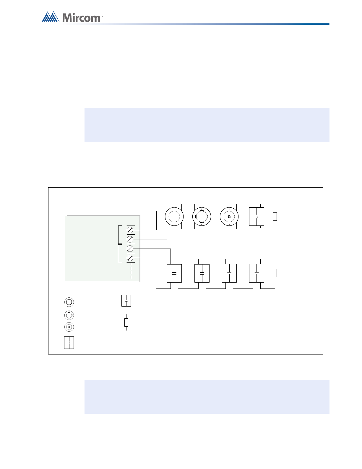
Figure 16 Initiating circuit – Class B or Style B wiring .................................................................... 29
Figure 17 Initiating circuit– Class A or Style D wiring ..................................................................... 30
Figure 18 Indicating circuit – Class B or Style Y wiring .................................................................. 30
Figure 19 Indicating circuit –Class A or Style Z wiring ................................................................... 31
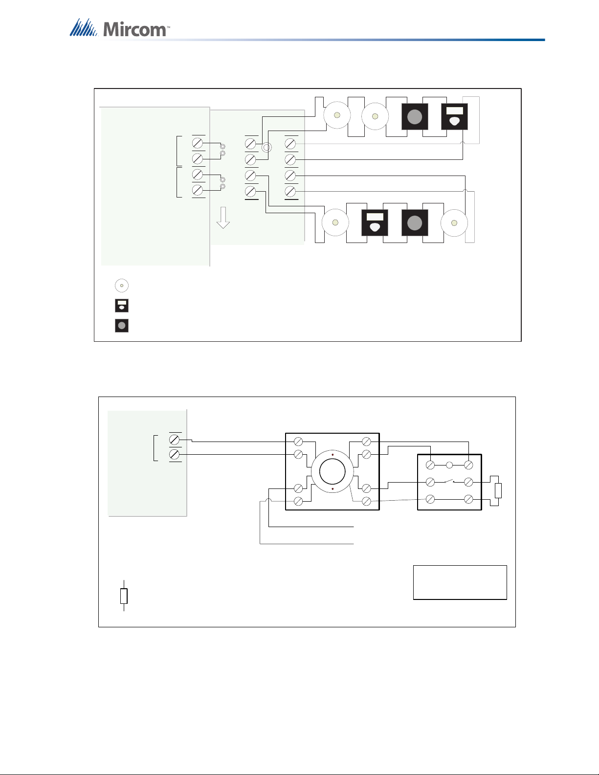
Figure 20 Four-wire smoke detector wiring .................................................................................... 31
Figure 21 Dialer wiring ................................................................................................................... 32
Figure 22 Relay per zone (RM-312) Terminal connection ............................................................. 32
Figure 23 Relay per zone (RM-306) Terminal connection ............................................................. 33
Figure 24 Connecting an FACP to a 3G4010CF Interface Device ................................................. 34
Figure 25 Polarity reversal and city tie module terminal connection .............................................. 35
Figure 26 Power supply connection ............................................................................................... 36
Figure 27 Battery connections ........................................................................................................ 40
Figure 28 LCD Display and control buttons .................................................................................... 42
Figure 29 Lamp test ....................................................................................................................... 44
Figure 30 Evacuation Codes .......................................................................................................... 48
Figure 31 FA-300 main LCD display .............................................................................................. 52
Figure 32 Enter passcode ......................................................................................................
Figure 33 Command Menu ............................................................................................................. 54
Figure 34 FA-300 Config menu ...................................................................................................... 55
Figure 35 Feature Config menu ..................................................................................................... 55
Figure 36 The event log ................................................................................................................. 64
Figure 37 Walk test confirmation .................................................................................................... 65
Figure 38 Walk test zones .............................................................................................................. 65
Figure 39 Walk test active .............................................................................................................. 65
Figure 40 i3 loop test confirmation ................................................................................................. 66
Figure 41 i3 test zones ................................................................................................................... 66
Figure 42 i3 test not ready .............................................................................................................. 67
Figure 43 The selected zone is not i3 type ..................................................................................... 67
........ 53
6
Page 7

List of Figures
Figure 44 Dialer Config menu ........................................................................................................ 67
Figure 45 Account Info menu ......................................................................................................... 68
Figure 46 Telephone Line menu .................................................................................................... 69
Figure 47 Report Options menu ..................................................................................................... 70
Figure 48 Time Parameter ............................................................................................................. 71
Figure 49 Dialer Test menu ............................................................................................................ 73
Figure 50 Detection circuit message .............................................................................................. 76
Figure 51 Indicating circuit message .............................................................................................. 76
Figure 52 AC Power Fail message ................................................................................................ 77
Figure 53 Battery trouble message ................................................................................................ 77
Figure 54 Ground Fault message .................................................................................................. 78
Figure 55 Remote Annunciator message ....................................................................................... 78
Figure 56 Four-wire smoke detector supply message ................................................................... 79
Figure 57 Supervised auxiliary supply message ............................................................................ 79
Figure 58 Module missing message .............................................................................................. 80
Figure 59 Module trouble message ................................................................................................ 80
7
Page 8

List of Tables
Table 1 FA-300 LCD Series Comparison Chart .......................................................................... 13
Table 2 Power Supply Ratings .................................................................................................... 36
Table 3 Initiating Circuit Wiring ................................................................................................... 37
Table 4 Indicating Circuit Wiring ................................................................................................. 37
Table 5 Troubleshooting ............................................................................................................. 41
Table 6 i3 detector LEDs ............................................................................................................. 51
Table 7 Feature Config menu ..................................................................................................... 56
Table 8 i3 Detector LEDs while in test mode .............................................................................. 67
Table 9 Compatible Receivers .................................................................................................... 81
Table 10 Ademco Event Code ...................................................................................................... 82
Table 11 SIA Event Codes ............................................................................................................ 83
Table 12 FA-300 LCD Series Specifications ................................................................................. 84
Table 13 FA-300 LCD System Modules and Annunciators ........................................................... 85
8
Page 9

1.0 Industry Canada and FCC Notice
!
i
1.1 Notice for all FA-300 Series Built-In UDACTs Sold in Canada
Mircom's FA-300 SERIES BUILT-IN UDACT Communicator described in this manual is listed
by Underwriters Laboratories Canada (ULC) for use in slave application in conjunction with a
Listed Fire Alarm Control Panel under Standard ULC-S527 (Standard for Control Units for Fire
Alarm Systems) and ULC/ORD-C693-1994 (Central Station Fire Protective Signalling Systems
and Services). These Communicators should be installed in accordance with this manual; the
Canadian / Provincial / Local Electrical Code; and/or the local Authority Having Jurisdiction
(AHJ).
1.1.1 Industry Canada Notice
Repairs to certified equipment should be made by an authorized Canadian maintenance
facility designated by the supplier. Any repairs or alteration made by the user to this
equipment, or equipment malfunctions, may give the telecommunications company cause to
request the user to disconnect the equipment. Users should ensure for their own protection
that the Earth Ground connections of the power utility, telephone lines and internal metallic
water pipe system, if present, are connected together. This is necessary both for proper
operation and for protection.
Caution: Users should not attempt to make such connections themselves, but
should contact the appropriate electric inspection authority, or
electrician, as appropriate.
1.1.2 Notice for all FA-300 Series Built-in UDACTs Sold in the U.S.A.
Notes: The Ringer Equivalence Number (REN) assigned to each terminal device
provides an indication of the maximum number of terminals allowed to be
connected to a telephone interface. The termination on an interface may consist
of any combination of devices subject only to the requirement that the sum of the
Ringer Equivalence Numbers of all the devices does not exceed 5.
The REN for this product is part of the product identifier that has the format
US:AAAEQ##TXXXX. The digits represented by ## are the REN without a
decimal point (e.g., 03 is a REN of 0.3). For earlier products, the REN is
separately shown on the label.
Mircom's FA-300 SERIES BUILT-IN UDACT Digital Communicator described in this manual
is listed by Underwriters Laboratories Inc. (ULI) for use in slave application in conjunction with
a Listed Fire Alarm Control Panel under Standard 864 (Control Units for Fire Protective
Signalling Systems). These Communicators comply with the National Fire Protection
Association (NFPA) performance requirements for DACTs and should be installed in
accordance with NFPA 72 Chapter 4 (Supervising Station Fire Alarm System). These
Communicators should be installed in accordance with this manual; the National Electrical
Code (NFPA 70); and/or the local Authority Having Jurisdiction (AHJ).
9
Page 10

1.1.3 FCC Notice
This equipment complies with Part 68 of the FCC rules and the requirements adopted by the
ACTA. On the telco transformer of this equipment is a label that contains, among other
information, a product identifier in the format US:AAAEQ##TXXXX. If requested, this number
must be provided to the telephone company. This equipment is capable of seizing the line.
This capability is provided in the hardware.
Type of Service: The Communicator is designed to be used on standard device telephone
lines. It connects to the telephone line by means of a standard jack called the USOC RJ-11C
(or USOC FJ45S). Connection to telephone company provided coin service (central office
implemented systems) is prohibited. Connection to party lines service is subject to state tariffs.
Telephone Company Procedures: The goal of the telephone company is to provide you with
the best service it can. In order to do this, it may occasionally be necessary for them to make
changes in their equipment, operations or procedures. If these changes might affect your
service or the operation of your equipment, the telephone company will give you notice, in
writing, to allow you to make any changes necessary to maintain uninterrupted service.
In certain circumstances, it may be necessary for the telephone company to request
information from you concerning the equipment which you have connected to your telephone
line. Upon request of the telephone company, provide the FCC registration number and the
ringer equivalence number (REN); both of these items are listed on the equipment label. The
sum of all of the REN’s on your telephone lines should be less than five in order to assure
proper service from the telephone company. In some cases, a sum of five may not be usable
on a given line.
Industry Canada and FCC Notice
If Problems Arise: If any of your telephone equipment is not operating properly, you should
immediately remove it from your telephone line, as it may cause harm to the telephone
network. If the telephone company notes a problem, they may temporarily discontinue service.
When practical, they will notify you in advance of this disconnection. If advance notice is not
feasible, you will be notified as soon as possible. When you are notified, you will be given the
opportunity to correct the problem and informed of your right to file a complaint with the FCC.
Contact your telephone company if you have any questions about your phone line. In the
event repairs are ever needed on the Communicator, they should be performed by Mircom
Technologies Ltd. or an authorized representative of Mircom Technologies Ltd. For information
contact Mircom Technologies Ltd. at the address and phone numbers shown on the back page
of this document.
10
Page 11

2.0 Introduction
i
Mircom's FA-300 Series Fire Alarm Control Panel is a Digital Signal Processor (DSP) based
fire panel. The FA-300 provides a maximum of 12 supervised Class B or A (style B or D)
Initiating circuits, and maximum of four supervised Class B or A (Style Y or Z) indicating
circuits. All circuits are supervised for opens and ground faults, and indicating circuits are
supervised for shorts. Optional modules include relay, polarity reversal and city tie and Class A
Converters for initiating and indicating circuits. Semi-flush or surface mountable backboxes
can be used for retrofits and on new installations.
Note: Installation of the FA-300 series fire alarm control panel should be in accordance
with Canadian Electrical Code Part 1, ULC-S524 installation of Fire Alarm
System, National Electrical Code NFPA 70 and NFPA 72. Final acceptance
subject to the Local Authority Having Jurisdiction (AHJ).
2.1 Overall Features
• The basic unit has six Class B (Style B) initiating circuits, which may be configured as
Class A (Style D) using input Class A converter adder module. Each initiating circuit can
be configured as alarm, verified alarm, water flow alarm, sprinkler alarm, latching or
non-latching supervisory, monitor or trouble circuits.
• The basic unit has two power limited Class B (Style Y) indicating circuits. Each
indicating circuit may be configured as Class A (Style Z) using an output Class A
converter adder module. Each indicating circuit may be configured as silenceable
signal, non-silenceable signal, silenceable strobe, non-silenceable strobe. The audible
signal may be Steady, Temporal Code, California Code, or March Time.
• Each initiating and indicating circuit can be individually disconnected via the keypad and
LCD display with password access.
• Configurable signal silence inhibit, auto signal silence, and one-man walk test.
• Four-wire resettable smoke power supply 300 mA maximum.
• Relay contacts for common alarm, common supervisory and common trouble all non-
disconnect-able and auxiliary alarm relay (disconnectable).
• RS-485 interface for RA-1000 series remote multiplex Annunciators, LCD Annunciators
and smart relay adder.
• Optional modules for additional relay circuits, city tie and polarity reversal signaling.
• Extensive transient protection.
• With or without built-in UDACT (Digital Alarm Communicator Transmitter).
• Easy configuration of the panel using front LCD display and keypad.
• Remote dial up (with built-in UDACT version) for event log checking and/or configuration
changing.
• Laptop programmer for direct configuration changing and log checking.
11
Page 12

3.0 Conventions
3.1 Circuits
Refers to an actual electrical interface for initiating (detection) and indicating (signal or NAC)
or relays
3.2 Zone
Is a logical concept for a Fire Alarm Protected Area, and consists of at least one circuit.
Often the terms zone and circuit are used interchangeably, but in this manual circuit refers
only to a physical electrical loop.
3.3 Events
There are events associated with every initiating, indicating and common circuit of the fire
panel displayed via the LCD.
3.4 Wiring Styles
Initiating and indicating circuits are Class B (Style B and Y).
Changing the initiating circuits to Class A requires an ICAC-306 adder board which will convert
six initiating zones from Class B (Style B) circuits to Class A (Style D). This is done without
decreasing the number of circuits, which remains the same as in Class B (Style B).
Changing the indicating circuits to Class A requires an OCAC-304 adder board which will
convert four indicating zones from Class B (Style Y) circuits to Class A (Style Z) or an OCAC302 adder board which will convert two indicating zones from Class B (Style Y) circuits to
Class A (Style Z).
12
Page 13

4.0 System Components
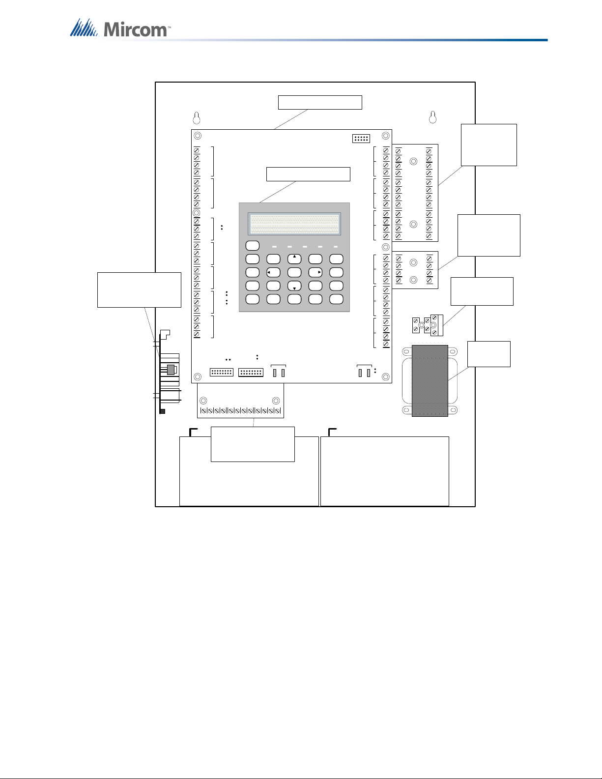
4.1 Main Fire Control Panel
Figure 1 FA-300 LCD
All FA-300 LCD series panels have the following features:
• LCD display
• Two six-zone ICAC-306 Input Class A converter adder modules may be used for
Class A (Style D) wiring of Initiating circuits.
• One OCAC-304 Output Class A converter adder module may be used for Class A
(Style Z) wiring of the indicating circuits.
• Common alarm, common supervisory and common trouble relays, auxiliary alarm relay
(disconnectable), an RS-485 interface for Remote Annunciators and a resettable four
wire smoke detector power supply.
• Used with BA-110 (10 Ah) (Sota Enertech model SA12120) batteries (two required).
Table 1 FA-300 LCD Series Comparison Chart
Model Number of
zones
FA-300-6DDR 6 6 y red
FA-300-6DR 6 6 n red
FA-301-12DDR 12 12 y red
Number of
initiating
circuits
On board Dialer Door Color
FA-300-6DDR-CG
Marine Fire Alarm
Control Unit
66 y red
13
Page 14
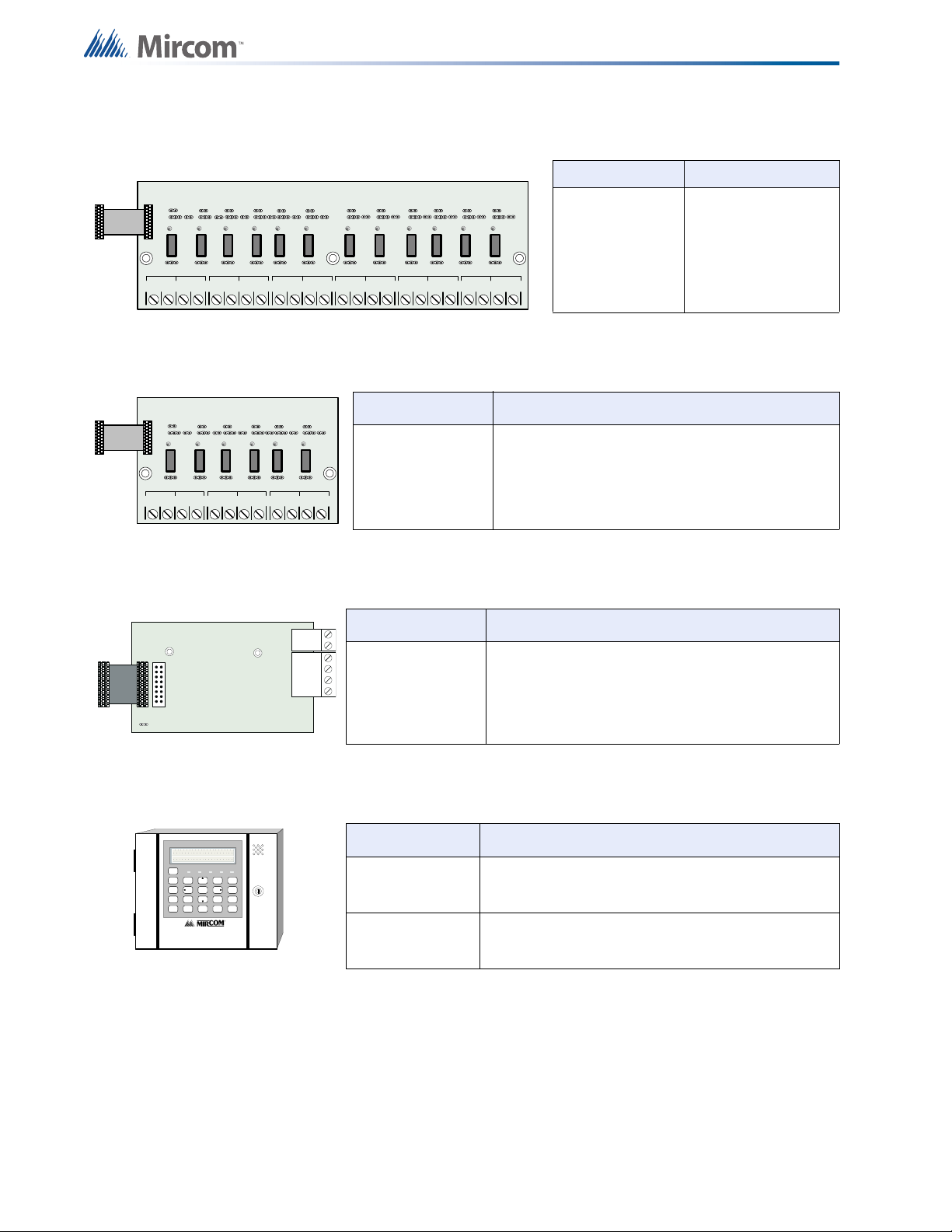
4.2 Relay Module: 12 Relays
NO/NC C
RELAY 1
NO/NC C
RELAY 2
NO/NC
C
RELAY 3
NO/NC C
RELAY 4CRELAY 5
NO/NC C
RELAY 6
NO/NC
C
RELAY 7
NO/NC C
RELAY 8CRELAY 9
NO/NC C
RELAY 10
NO/NC
C
RELAY 11
NO/NC C
RELAY 12
NO/NC NO/NC
NO/NC C
RELAY 1
NO/NC C
RELAY 2
NO/NC
C
RELAY 3
NO/NC C
RELAY 4CRELAY 5
NO/NC C
RELAY 6
NO/NC
POLARITY
REVERSAL
ALARM
POLARITY
REVERSAL
SUPV
CITY
TIE
+ | - + | - + | -
JW4
P1 P2
FA-300 SERIES
Remote Annunciator
SYSTEM
RESET
SIGNAL
SILENCE
FIRE
DRILL
BUZZER
SILENCE
LAMP
TEST
1
4
7
*
2
5
8
0
3
6
9
#
ENTER
MENU
CANCEL
INFO
ABC DEF
GHI JKL MNO
PRS
TUV
WXY
QZ
A.C. ON ALARM SUPV TRBL CPU FAIL
SYSTEM NORMAL
18:01 MON 2003-04-05
Advanced Li fe Safety Sol utions
System Components
Model Description
4.3 Relay Modules: Six Relays
Model Description
RM-306 Six relay adder module
4.4 Polarity reversal/city tie
Model Description
RM-312
12 relay adder
module
14
4.5 Remote Annunciator
PR-300 Polarity reversal and/or city tie module
Model Description
RAM-300LCDW
RAM-300LCDR
Remote annunciator module, LCD display, white
painted box
Remote annunciator module, LCD display, red
painted box
Page 15
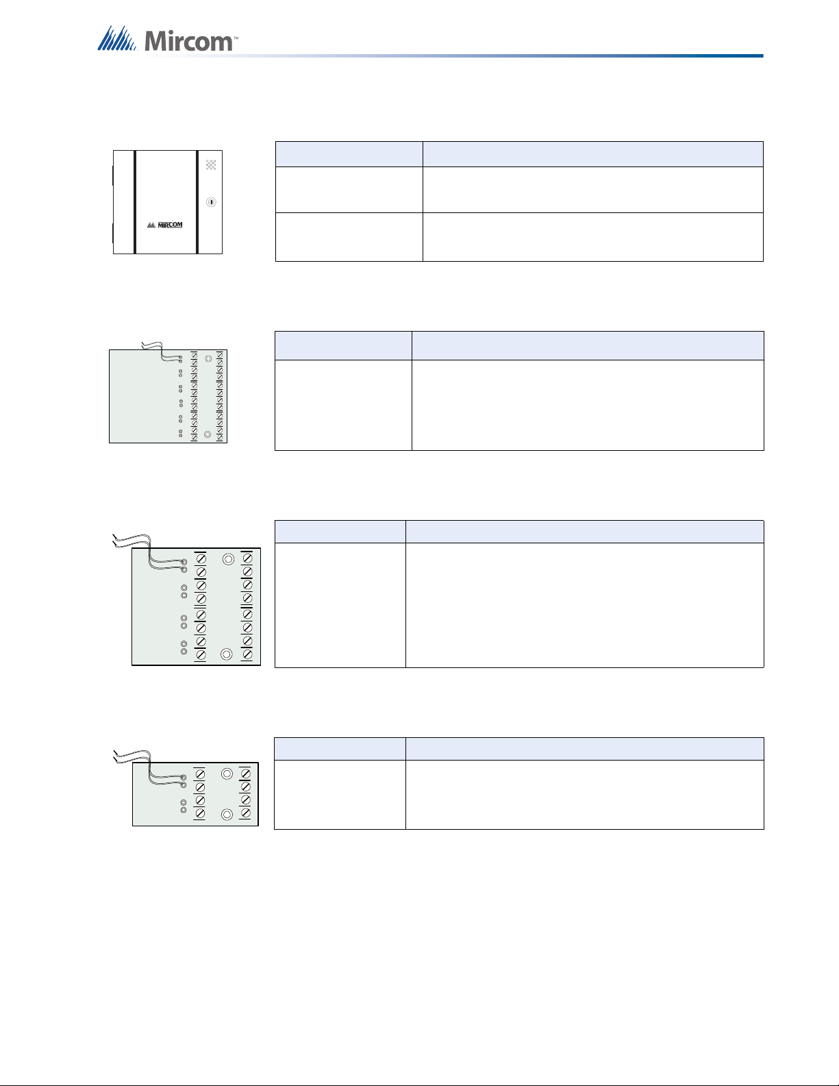
4.6 Smart Relay Module
REMOTE RELAY
Advanced Life Safety Sol utions
FR-320 SERIES
BLK RED
BLK REDBLK REDBLK REDBLK REDBLK RED
- DET1 OUT+- DET2 OUT+- DET3 OUT+- DET4 OUT+- DET5 OUT+- DET6 OUT+
- DET1 RET+- DET2 RET+- DET3 RET+- DET4 RET+- DET5 RET+- DET6 RET+
- SIG1 OUT+- SIG2 OUT+
- SIG1 RET+- SIG 2 RET+
BLK RED
BLK RED
- SIG3 OUT+- SIG4 OUT+
- SIG3 RET+- SIG 4 RET+
BLK RED
BLK RED
- SIG1 OUT+- SIG2 OUT+
- SIG1 RET+- SIG2 RET+
BLK RED
BLK RED
Model Description
SRM-312W Smart relay module (12 relays) with white enclosure
SRM-312R Smart relay module (12 relays) with red enclosure
4.7 Input Class A converter: Six Circuits
Model Description
System Components
ICAC-306
Input Class A converter module (six circuits). This
module has built in active end-of-line resistors.
4.8 Output Class A converter: Four Circuits
Model Description
OCAC-304 Output Class A converter module (four circuits)
4.9 Output Class A converter: Two Circuits
Model Description
OCAC-302 Output Class A converter module (two circuits)
15
Page 16
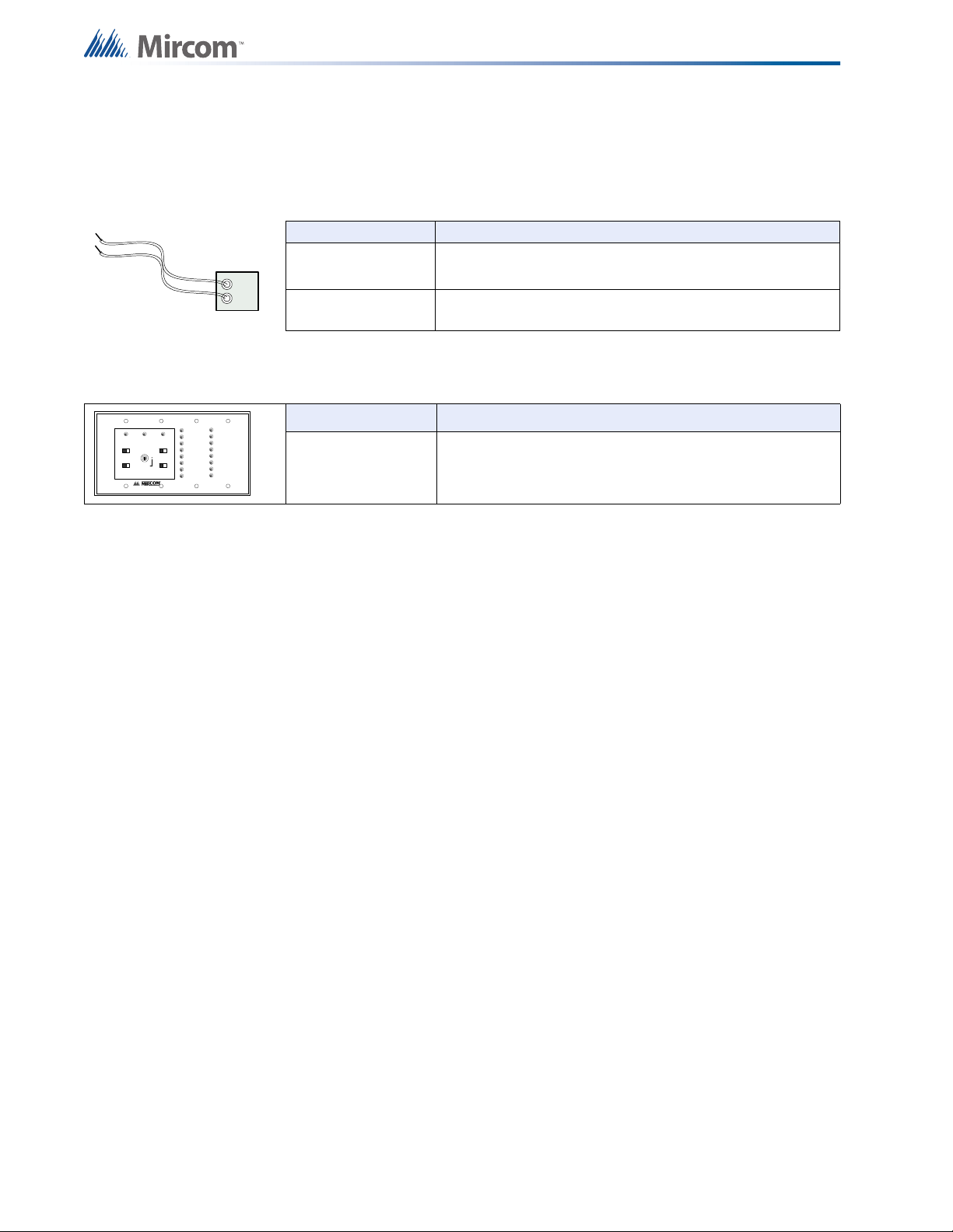
4.10 Active end-of-line resistor
BLACK
RED
A.C.ONCOMMON
TROUBLE
SIGNAL
SILEBCE
BUZZER
SILENCE
SIGNAL
SILENCE
LAMP
TEST
SYSTEM
RESET
SWITCH
ENABLE
FIRE ALARM
ANNUNCIATOR
The ELRX-300 are power-saving end-of-line resistors that eliminate the need for an additional
battery cabinet or larger batteries in order to meet the 60 hour standby requirement.
Model Description
ELRX-300 Active end-of-line resistor without plate
ELRX-300R Active end-of-line resistor with end-of-line red plate
4.11 RAM-216 Remote Annunciator
Model Description
RAM-216 16 zone remote annunciator
System Components
4.12 Additional Fire Alarm System Accessories
RAM-208 Eight zone remote annunciator (ULC and ULI approved)
RTI-1 Remote trouble indicator (ULC and ULI approved)
MP-300
End-of-line resistor plate, 3.9 k
Ω
MP-300R End-of-line resistor plate, red (ULC approved)
BC-160 External battery cabinet (ULC and ULI approved)
(ULC and ULI approved)
16
Page 17
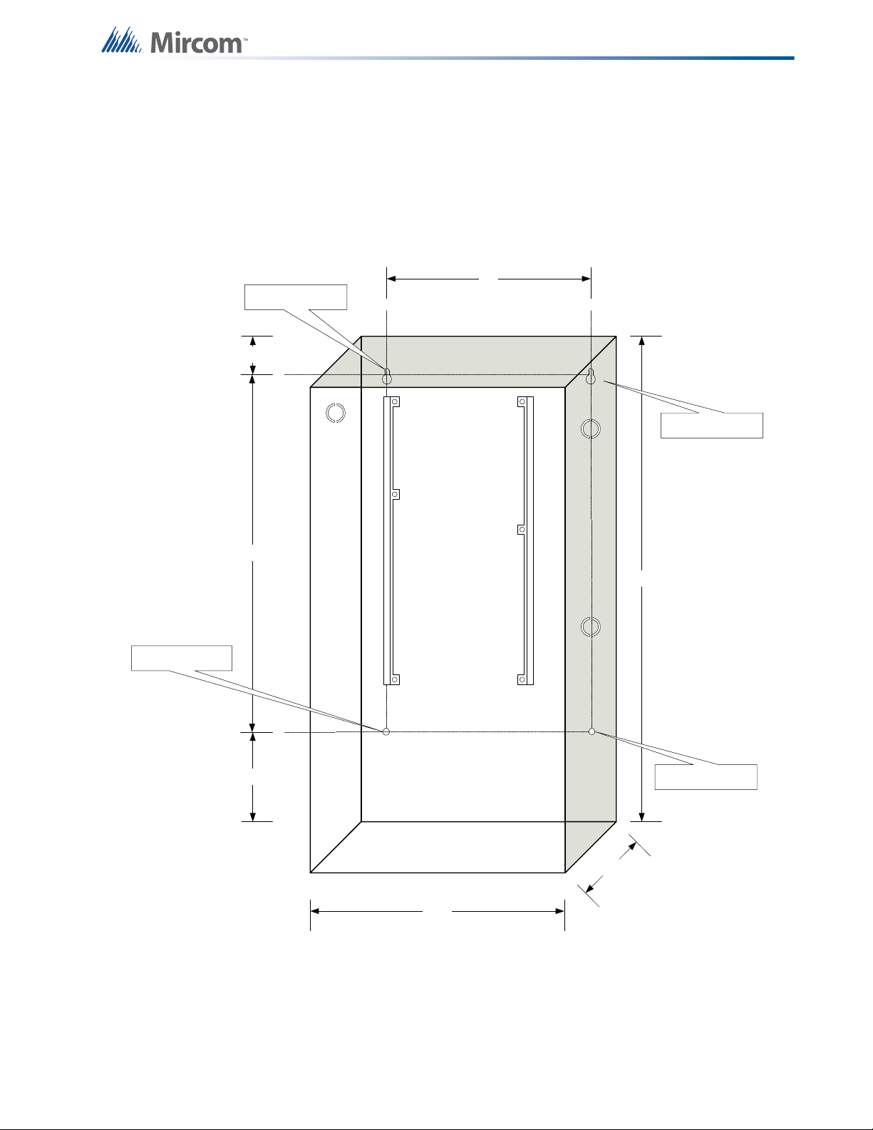
5.0 Mechanical Installation
11"
14.5"
1.5"
20.5"
5.4"
4.5"
25.9"
Mounting Hole
Mounting Hole
Mounting Hole
Mounting Hole
5.1 Installing the Enclosure
Install the FA-300 series fire alarm panel enclosure as shown below for the 12 zone, eight
zone, and six zone models. Mount enclosure surface mount using the four mounting holes, as
shown and the screws provided.
Figure 2 Enclosure dimensions, surface mount
The enclosure may be semi-flush mounted using the trim ring model FA-UNIV-TRB (BLACK),
see Figure 3. Remove the door (also disconnect the ground strap), the dead front and semi-
17
Page 18
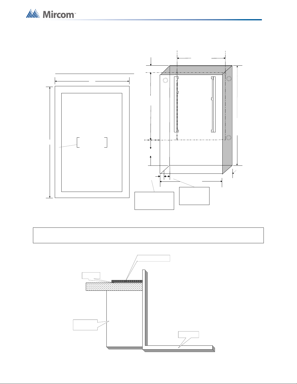
Mechanical Installation
14.5"
4
.
5
"
11"
26"
1.5"
5.4"
20.5"
3.5"
1"
3.5" i s the max imum
depth for semi -flus h
mounting usi ng the
flush tr im ri ng
1" is the mi nimum depth
above the wall required for
semi- flus h mounting usi ng the
flus h trim ri ng
17"
28.5"
Adhere tr im ri ng to
wall surfac e around
FA- 300 backbox .
PLACE FA-UNIV-TRB TRIM RING OVER BACKBOX
TRIM RING
WALL
WOOD OR
METAL STUD
BACKBOX
flush mount the enclosure into the wall. Peel the adhesive cover from the trim ring and stick to
the wall surface around the enclosure, after the wall is finished.
Figure 3 Enclosure dimensions, semi-flush mounting and trim ring
Figure 4 shows a cross-section of the semi-flush mounted enclosure and the trim ring. Make sure to allow
a minimum depth of 1” above the wall surface for proper door opening.
Figure 4 Flush trim detail (from above)
18
Page 19
Mechanical Installation
26.0 "
14.5 "
4.2 "
External Dimensions
1.3 "
1.7 "
2.0 "
Top View
2.1 "
1.3 "
6.0 "
9.5 "
Side View
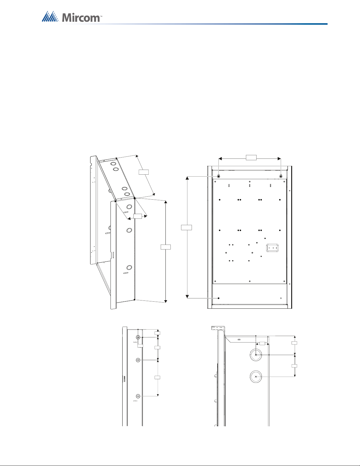
5.2 BBX-1024DS and BBX-1024DSR Mechanical Installation
The BBX-1024DS and BBX-1024DSR are suitable for flush or surface mounting, and have a
built-in trim ring.
Dimensions of enclosure (minus built-in trim ring) 14.5” x 4.2” x 26”
Distance between horizontal mounting screws 12”
Distance between vertical mounting screws 23.5”
Complete dimensions of enclosures 16.3” x 5.5” x 27.5”
Mounting Dimensions
12.0 "
23.5 "
Figure 5 BBX-1024DS and BBX-1024DSR installation instructions and dimensions
19
Page 20
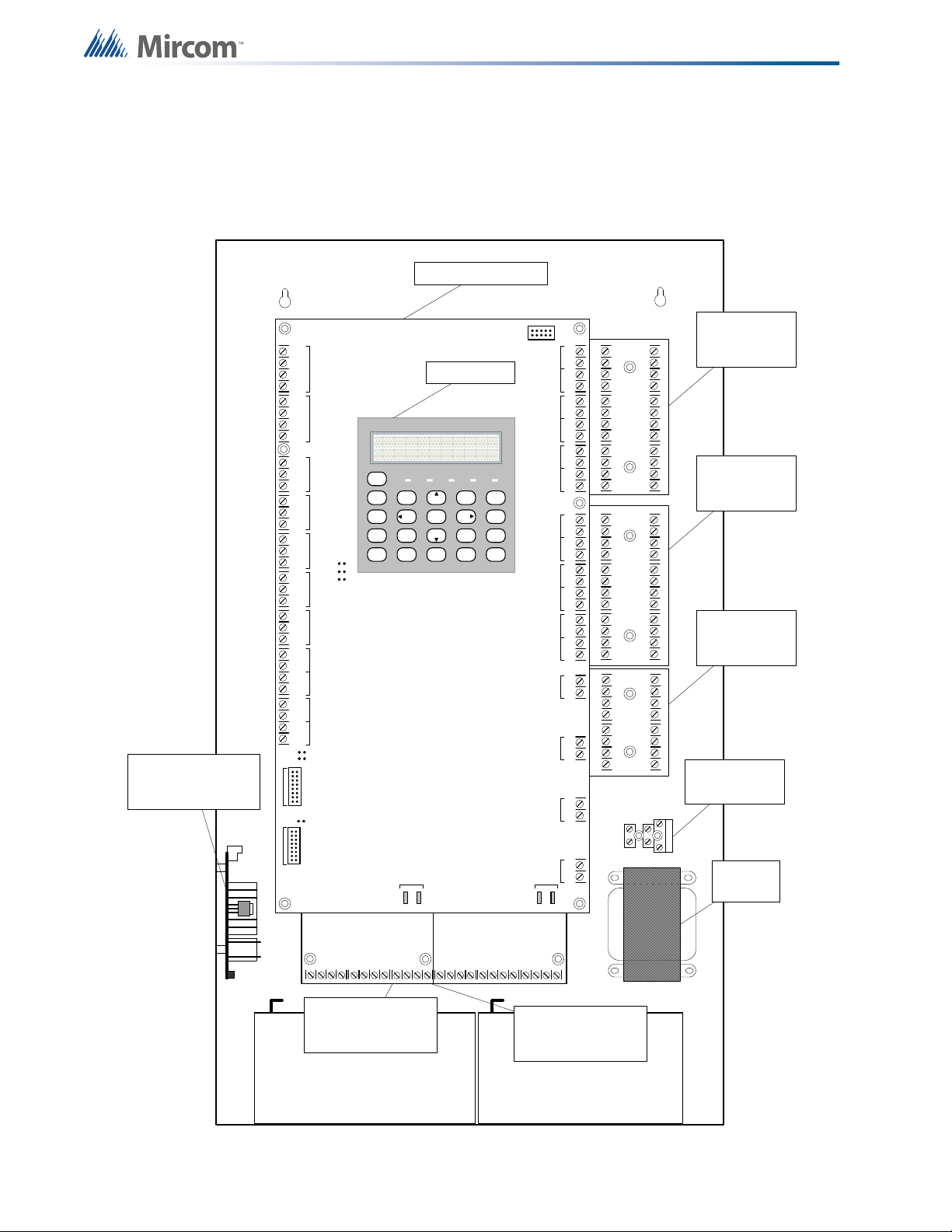
5.3 Installing the Adder Modules
S-+NC N OCNC NOCNC NOCNC NOC
+-+-COM(+)
COM(-)
TRLTRB RTRT RTR T
RES CO RES CO
LINE1LINE2
JW3
JW2
JW1
-+-+-+-+-+-+-+-+-+-+-+-+-+-+-+-+
DET 1DET 2DET 3DET 4DE T 5DET 6DET 7DE T 8DET 9DET 10DET 11DET 12SI G 1SIG 2SIG 3SIG 4
JW6
JW5
JW4
TO PR-300 MODULE
TO RM -312/RM-306 RELAY
MODULE
RS-
485
AUX. RELA YALARM
RELAY
SUP E RVIS O R Y
RELAY
TROU BLE
RELAY
AUX
SUPPLY
4-W I R E
SUPPLY
UNFILTERED
RTI
PORT
P1P
2
P3P
4
+
_
BATTERY SEC. TX
BATTERY BATTERY
CLASS -A con verter
board for detection
circui ts ICAC-306 (6
cir cuits )
CLASS -A con verter
board for detection
circui ts ICAC-306 (6
cir cuits )
CLASS -A con verter
board for indicating
circui ts OC AC-304
(4 circuits )
Reverse po larity a nd city
tie module PR -300.
Mounted on hex spacer
with two screws provid ed
Relay Module RM-306
Mount relay module on the
left side using two screws
provided .
Relay M odule RM-312
centre under main fire
alarm board using three
screws pro vided .
Transformer
Fuse and AC wirung
termina l
MAIN FIR E PANEL BOAR D
SYST EM
RESET
SIGNAL
SILEN C
E
FIR E
DRILL
BU ZZER
SILEN C
E
LAMP
TEST
1
4
7
*
2
5
8
0
3
6
9
#
ENT ER
MENU
CANCEL
INFO
ABC DEF
GHI JKL MNO
PRS
TUV
WXY
QZ
A.C. ON ALAR M SUPV TR BL CPU FAIL
SYSTEM NORMAL
18:01 MON 2003-04-05
LCD DISPLAY
Fuse and AC
wiring terminal
FA-300 series fire alarm panels come pre-assembled with all components and boards except
for adder modules. Module installation locations are shown in Figures 6 and 7. Refer to "6.1.1
Connectors and Jumpers on the Main Fire Alarm Board" on page 24 for jumper or DIP switch
settings and see "7.6 Wiring Tables and Information" on page 37 for wiring information.
Mechanical Installation
20
Figure 6 Installation of adder modules for FA-301 LCD
Page 21
Mechanical Installation
BATTERY BATTERY
CLASS-A
converter board
for detection
circuits IC AC-306
(6 cir cuits )
CLASS-A con verte r
board for indicating
circuits O CA C-302
(2 cir cuits )
Reverse polarity an d city
tie mo dule PR-300.
Mounted on hex spacer
with two screws provided
Relay Mo dule RM-306
Mount rela y module on the
left side usin g two screw s
provided .
LCD configuration
tool - C FG-300
plugged i nto the
socket sh own .
Transformer
Fuse and AC wirung
termin al
MAIN FIRE PANEL BOARD
S-+NC N OCNC NOCNC NOCNC NOC
COM(+
)
COM(-)
TRLTRB
RTRT RT RT
RES CO RES CO
LINE1LINE2
JW2
JW1
-+-+-+-+-+-+-+-+-+-+
DET
1
DET
2
DET
3
DET
4
DET
5
DET
6
SIG 1SIG 2
TO PR-300
MODULE
TO RM-312/RM-306 RELAY
MODULE
RS-
485
AUX. REL AY
ALARM
RELAY
SUPERVISORY
RELAY
TROUBLE
RELAY
AUX
SUPPLY
4-WIRE
SUP PLY
UNFI LTERED
RTI
PORT
P1 P 2P3 P4
+
_
BATTERY SEC. TX
SYST EM
RESET
SIGNAL
SILEN C E
FIRE
DRILL
BUZZER
SILEN C E
LAMP
TEST
1
4
7
*
2
5
8
0
3
6
9
#
ENT ER
MENU
CANCEL
INFO
ABC DEF
GHI
JK
L
MNO
PRS
TUV
WXY
QZ
A.C. ON ALARM SUPV TRBL CPU FAIL
SYSTEM NORMAL
18:01 MON 2003-04-05
AUX
SUPPLY
P5 P6
JW3
JW4
JW5
JW7
LCD DISPLAY
Figure 7 Installation of adder modules for FA-300 LCD
21
Page 22

S-+NC NOCNC NOCNC NOCNC NOC
+-+-
COM(+)
CO M(- )
TRLTRB RTRT RTRT
RES CO RES CO
LINE1LINE2
JW3
JW2
JW1
-+-+-+-+-+-+-+-+-+-+-+-+-+-+-+-+
DET 1DET 2DET 3DET 4DET 5DET 6DET 7DET 8DET 9DET 10DET 11DET 12SIG 1SIG 2SIG 3SIG 4
JW6
JW5
JW4
TO PR-300 MODUL E
TO RM-312/RM-306 RELAY MODULE
RS-4 85AUX. RELAYAL ARM RE LA Y
SUPERVISO RY
RELAY
TRO UBL E
RELAY
AUX
SUPPLY
4-WIRE
SUPPLY
UN FILTERED
RTI
PORT
P1 P 2P3 P4
+
_
BA TTER Y SEC. TX
Telephon e line
#1
Telephon e line
#2
RS-485 for
annunciators
Auxiliary Relay
Alar m Relay
Supervisory Rela y
Troub le Relay
Auxiliary Supply
4-w ir e Su pp ly
Unfiltered 24V
supply
conne ct to Remo te
trouble indicator
Initiating zone 1 TO 12
Indicating zone 1 TO 4
Connect to RM-312/
RM306 Relay
module
Connect to PR-3 00
To Batte ry To seco ndary of AC
transformer
JW2 - ON- when
RM312/RM306 not
connected
JW1 - ON- when
PR- 300 not connected
JW3- Remove d all th e time
JW6 -Open all the time
JW5 -Normally Open
SYSTEM
RESET
SIGNAL
SILENCE
FIRE
DRILL
BUZZER
SILENCE
LAMP
TEST
1
4
7
*
2
5
8
0
3
6
9
#
ENTER
MENU
CANCEL
INFO
ABC DEF
GHI JKL MNO
PRS
TUV
WXY
QZ
A.C. ON ALARM SUPV TRBL CPU FAIL
SYSTEM NORMAL
18:01 MON 2003-04-05
JW4 -No rmally Open
JW7
JW7- Normally Open
For PC programming use UIMA
interface module not UL-864 or
ULC-S527 listed. Please r efer to
Document LT-929 for details
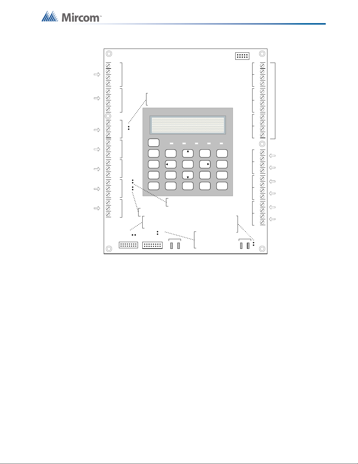
6.0 Connections, DIP Switches, and
Jumpers
6.1 Main Fire Alarm Board
22
Figure 8 Main fire alarm board connections, DIP switches and jumpers for FA-301 LCD
Page 23
Connections, DIP Switches, and Jumpers
S-+NC NOCNC NOCNC NOCNC NOC
CO M(+ )
CO M(- )
TRLTRB
RTRT RTRT
RES CO RES CO
LINE1LINE2
JW2
JW 1
-+-+-+-+-+-+-+-+-+-+
DET 1DET 2DET 3DET 4DET 5DET 6
SIG 1SIG 2
TO PR-300 MO DULE TO RM-312/RM-306 RELAY MODULE
RS-4 85AUX. RELAYAL ARM RE LA Y
SUPERVISORY
RELAY
TROU BL E
RELAY
AUX
SUPPLY
4-WIRE
SUPPLY
UNFIL TERED
RTI
PORT
P1 P 2P3 P4
+
_
BA TTERY SEC. T X
Teleph one line
#1
Teleph one line
#2
RS-48 5 for
annunciators
Auxiliary Rela y
Alarm Rela y
Superviso ry Rela y
Trouble Relay
Initiating zone 1 TO 6
To Batte ry To secondary of AC
tran sformer
JW2 - ON- when
RM312/RM306 not
connected
JW1 - ON- when
PR-300 not connected
SYSTEM
RESET
SIGNAL
SILENCE
FIRE
DRILL
BUZZER
SILENCE
LAMP
TEST
1
4
7
*
2
5
8
0
3
6
9
#
ENTER
MENU
CANCEL
INFO
ABC DEF
GHI JKL MNO
PRS
TUV
WXY
QZ
A.C. ON ALARM SUPV TRBL CPU FAIL
SYSTEM NORMAL
18:01 MON 2003-04-05
AUX
SUPPLY
P5 P6
JW 3
JW3
Remo ved all
the time
JW4
JW5
JW7
JW7
Normally open
JW4 - Nor mally Open
JW5 - Nor mally Open
For PC progr amming use UIMA
interface module not UL-864 or
ULC-S527 listed . Please refer to
Document LT-929 for details
Signal Circuit- 1
Signal Circuit- 2
Auxilia ry
Supply
4-w ir e S up pl y
Unfiltered 24V
supply
Connect to
Remote Troub le
Indicator
Figure 9 Main fire alarm board connections, DIP switches and jumpers for FA-300 LCD
23
Page 24
Connections, DIP Switches, and Jumpers
BLK RED
BLK REDBLK REDBLK REDBLK REDBLK RED
- DET1 OUT+- DET2 OUT+- DET3 OUT+- DET4 OUT+- DET5 OUT+- DET6 OUT+
- DET1 RET+- DET2 RE T+- DET3 RET+- DET4 RET+- DET5 RET+- DET6 RE T+
mounting hole for
#6-32 screws
All these pins comes with
red and black wires which
are connected to the
detection circuit on the
main fire alarm board. Red
is positive and black is
negative
ICAC-306
mounting hole for
#6-32 screws
6.1.1 Connectors and Jumpers on the Main Fire Alarm Board
P5 Cable from P1 of the PR-300 polarity reversal and city tie module connects here.
Otherwise not used.
P6 Cable from connector P1 of the RM-312 or RM-306 relay adder module connects
here. Otherwise not used.
JW1
Remove this jumper if a PR-300 polarity reversal and city tie module is installed.
JW2
JW3
Remove this jumper if an RM-312 or RM-306 relay adder module is installed.
Removed all the time.
JW4 Normally open. Place jumper here and power down (AC and batteries) then power
back to restore the default passcode (1111 ). After the system restarts, remove the
jumper from JW4.
JW5 Normally open to prevent configuration with a modem, a PC with a UIMA
converter module, or a CFG-300 configuration tool. Place a jumper here to allow
any type of configuration.
JW6
JW7
Not used, open.
Not used, open.
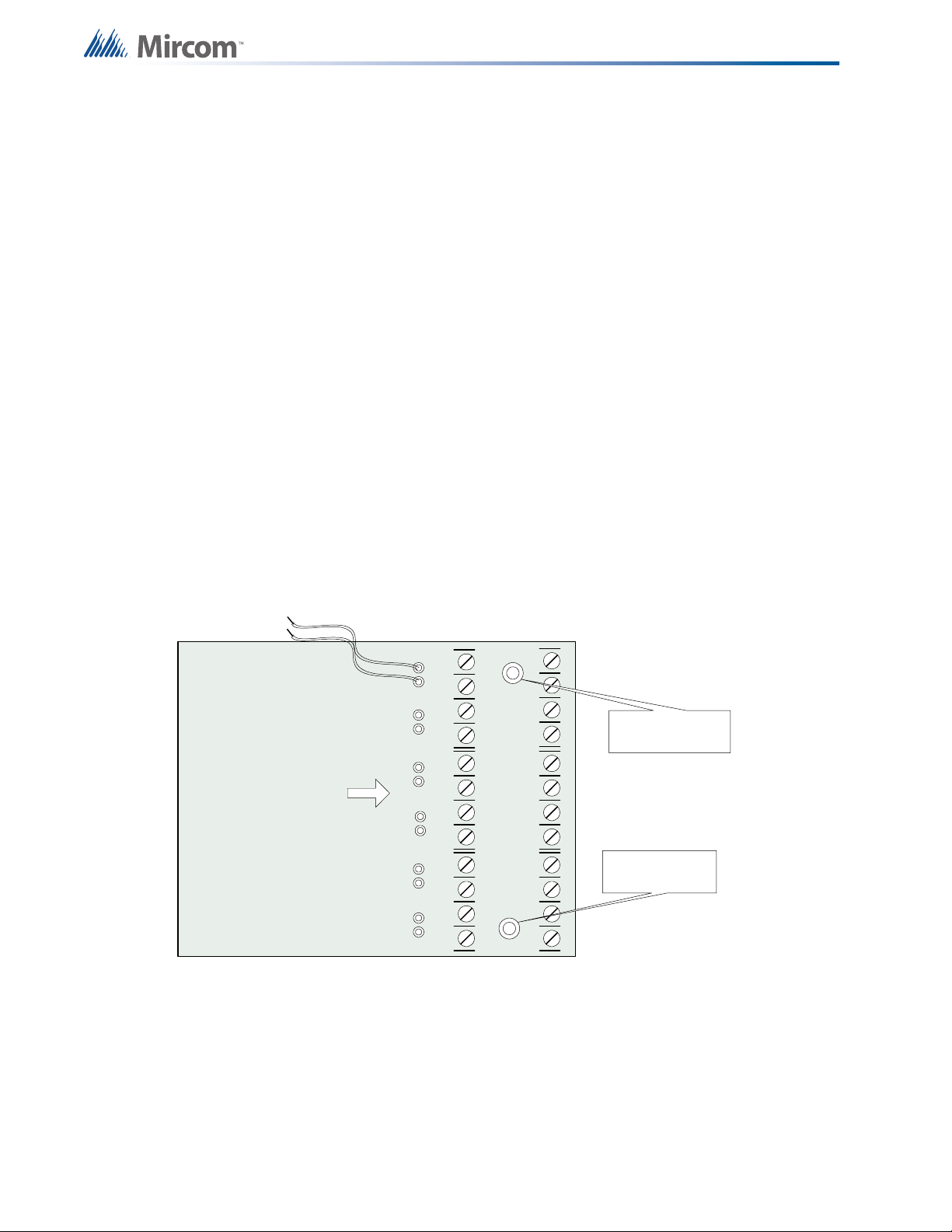
6.2 ICAC-306 Input Class A Converter Adder Module
24
Figure 10 ICAC-306 Input Class A converter adder module
There are no jumpers or cables to set on this module, just wiring from the converter (wires are
fixed here) to the Main Fire Alarm Board.
Initiating circuits must be wired from the ICAC-306 module to the Main Fire Alarm board. For
example, Initiating circuit 1 positive (red) and negative (black) wires are connected to the
positive and negative terminals (respectively) of Initiating circuit 1 on the Main Fire Alarm
Board. From the ICAC-306 converter Initiating circuits are wired out to the devices from the
Page 25
Connections, DIP Switches, and Jumpers
i
- SIG1 OUT+- SIG2 OUT+
- SIG1 RET+- SIG2 RET+
BLK RED
BLK RED
mounting hole for
#6-32 screws
OCA C-302
mounting hole for
#6-32 screws
- SIG1 O UT+- SIG2 OUT+
- SIG1 RET+- SIG2 RET+
BLK RED
BLK RED
- SIG3 OUT+- SIG4 OUT+
- SIG3 RET+- SIG4 RET+
BLK RED
BLK RED
mounting hol e for
#6-32 scr ews
OCA C -304
mounting hol e for
#6-32 screws
positive and negative terminals marked DET OUT and the circuit return wires are brought back
to the converter module to positive and negative terminals marked DET RET.
To convert all 12 initiating circuits of a FA-312 Fire Alarm Panel, two of these ICAC-306 input
Class A converter adder modules are required.
Note: This module has built in active end-of-line resistors and so the fire alarm system
should be configured to enable active end-of-line. See "11.0 Configuration" on
page 52.
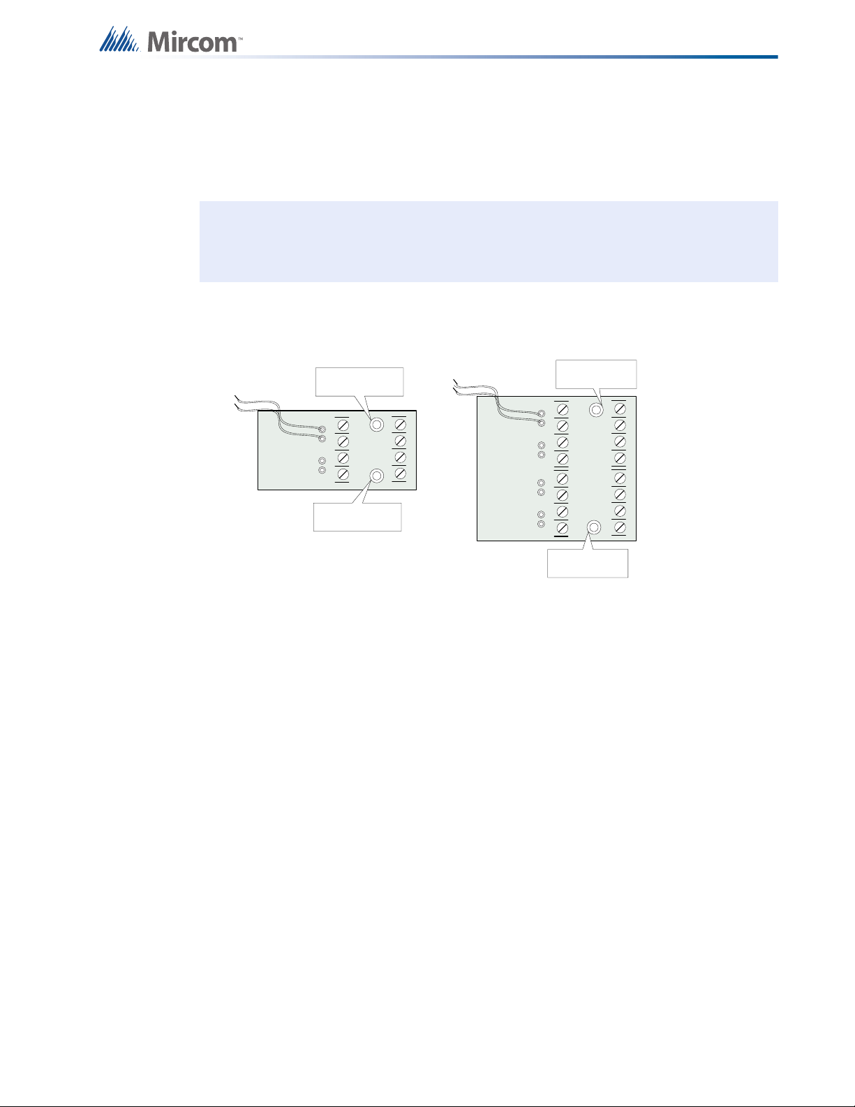
6.3 OCAC-304/302 Output Class A Converter Adder Module
Figure 11 OCAC-304/302 Output Class A converter adder module
Indicating circuits must be wired from the OCAC-304/302 to the main Fire Alarm board. For
example indicating circuit 1 positive (red wire) and negative (black wire) is wired from the
Class A converter module to the positive and negative terminals of Indicating circuit 1 on the
Main Fire Alarm board.
The actual indicating zone is wired from the SIGNAL OUT positive and negative to the
signaling devices and then wired back to the SIGNAL RET positive and negative.
6.4 Relay Adder Modules (Models RM-312 and RM-306)
6.4.1 RM-312 Twelve Relay Adder Module
The ribbon cable from P1 of the RM-312 is connected to P6 on the Main Fire Alarm Board.
The jumpers located above each relay on the RM-312 are used to configure the relays. The
25
Page 26
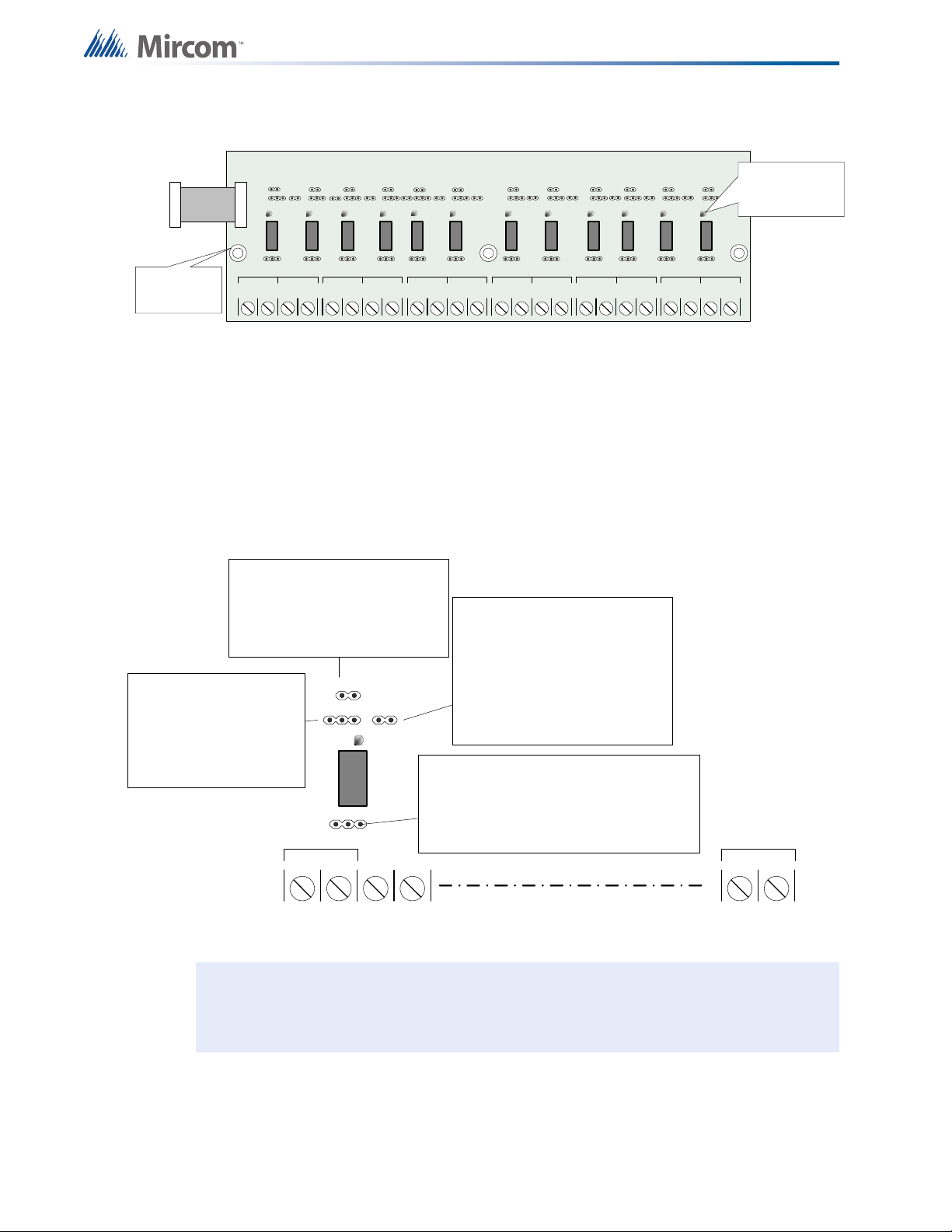
jumpers located below the relays are used to select either normally open contacts or normally
NO/NC C
RELAY 1
NO/NC C
RELAY 2
NO/NC C
RELAY 3
NO/NC C
RELAY 4CRELAY 5
NO/NC C
RELAY 6
NO/NC C
RELAY 7
NO/NC C
RELAY 8CRELAY 9
NO/NC C
RELAY 1 0
NO/NC C
RELAY 1 1
NO/NC C
RELAY 1 2
NO/NC NO/NC
Three mounting
holes for #6-32
screws
INDIVIDUAL
GREEN RELAY
STATUS LEDs
Connect to P6 on the
main fire alarm board
NO NC
SA
Z1
1&2
NO/ NC C
RELAY 1
NC/NO CONNECTION
NC: terminal provides normally closed contacts
NO: terminal provides normally open contacts
Default: jumper is installed on normally open (NO)
Note: if the jumper is not installed on any selection
then the relay is not connected to the terminals
SUPV/ALARM SELECTION
S: Relay turns ON when common
supervisory is active
A: Relay turns ON when common
alarm is active
Default: No jumper installed,
con nect e d on cent e r pin o nly
ZONE JUMPER
installed: turns ON relay when the zone
(1) i s act i ve
removed: does not turn ON the relay when
zone (1) i s act ive
Default: Jumper is installed
LOGICAL OR WITH ADJACENT ZONE
jumper installed: this relay 1 works in
conjunction with relay 2
jumper removed: relay 1 does not
operate with the adjacent relay 2
chaining example:if jumper is installed
on 1&2 and 2&3 then all the three relays
will be ON if any one of relays 1,2 and 3 is
active
Default: No jumper installed, connected
on one pin only
NO/ NC C
RELAY 12
RELAY
LED (G RE EN)
i
closed contacts.
Figure 12 RM-312 twelve relay adder module
P1 Cable from RM-312 Relay Adder Module connects to P6 on Main Fire Alarm
Board.
6.4.2 Programming the relays
Connections, DIP Switches, and Jumpers
26
A typical relay circuit is shown in Figure 13 with the jumper locations and descriptions.
Figure 13 RM-312/306 Relay programming
Note: Relay programming should be done before installing the board.
Page 27
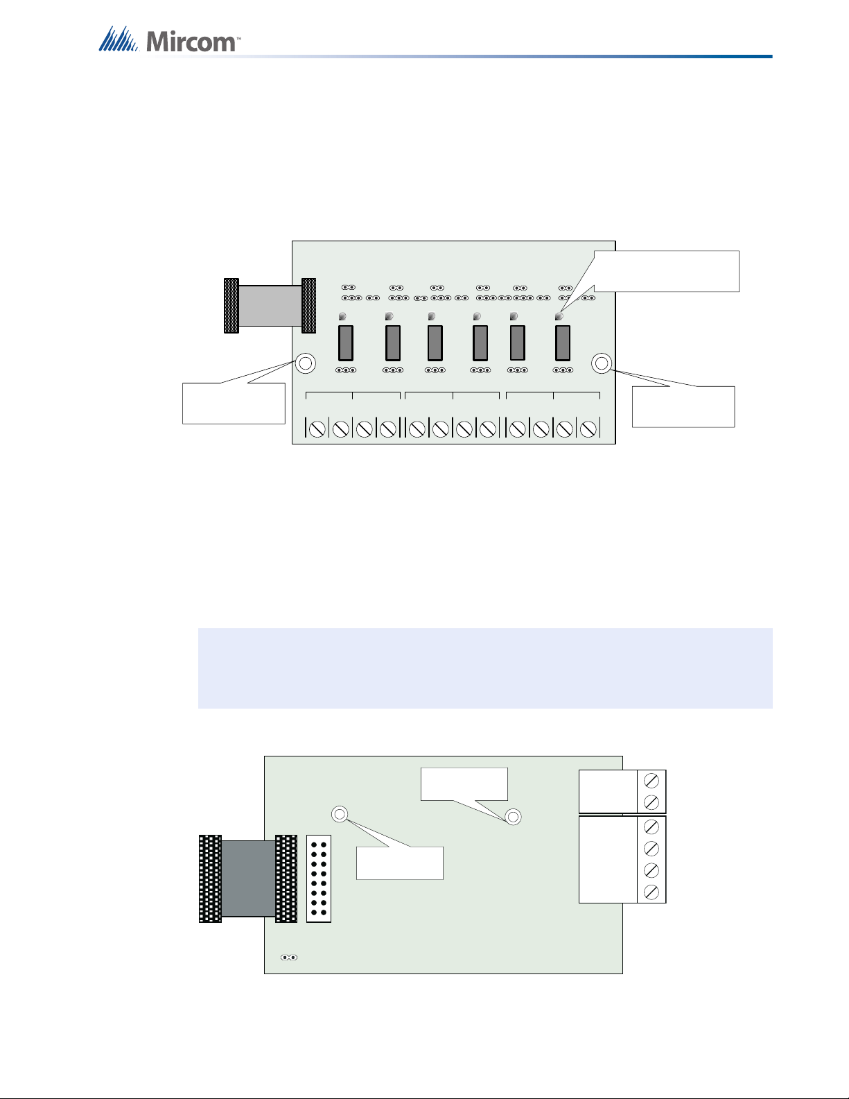
6.5 RM-306 Six Relay Adder Module
NO/ NC C
RELAY 1
NO/ NC C
RELAY 2
NO/NC C
RELAY 3
NO/NC C
RELAY 4CRELAY 5
NO/ NC C
RELAY 6
NO/NC
mounting hole
for #6-32 screws
mounting hole
for #6-32 screws
INDIVIDUAL GREEN
RELAY STAT US LEDs
Connect to P 6 on the
main fire alarm board
i
Cable from P1 of the RM-306 is connected to P6 on the Main Fire Alarm Board. The jumpers
located above each relay on the RM-306 are used to configure the relays. The jumpers
located below the relays are used to select either normally open contacts or normally closed
contacts.
Connections, DIP Switches, and Jumpers
Figure 14 RM-306 six relay adder module
P1 Cable from RM-306 Relay Adder Module connects to P6 on Main Fire Alarm
Board.
6.5.1 Programming the relays
See the explanation in Figure 13.
Note: Relay programming should be done before installing the board.
6.6 Polarity Reversal and City Tie Module (Model PR-300)
Mounting hole for
#6-32 screws
P1 P2
Mounting hole for
#6-32 screws
+ | - + | - + | -
TIE
ALARM
SUPV
CITY
REVERSAL
POLARITY
REVERSAL
POLARITY
JW4
Figure 15 Polarity reversal and city tie module
27
Page 28

The following hardware configuration must be performed before installing the PR-300.
6.6.1 PR-300 jumper settings
Connections, DIP Switches, and Jumpers
P1
P2 & JW4
Cable connects to P3 on the Main Board
Not used. Jumper JW4 remains on board.
The Alarm Transmit signal to the PR-300 can be programmed to turn OFF when signal silence
is active. This allows the City Tie Box to be manually reset. On subsequent alarms the
silenceable signals will resound and the City Tie Box will be retriggered.
The Trouble Transmit signal to the PR-300 can be programmed to delay AC power fail for 0, 1
or 3 hours if this is the only system trouble.
28
Page 29
7.0 Field wiring
!
+
-
STYLE B
WIRING
STYLE B
WIRING
INITIATING
CIRCUIT #1
INITIATING
CIRCUIT #2
INITIATING
CIRCUIT - 1
ALARM ZONE
INITIATING
CIRCUIT - 2
SUPERVISORY
ZONE
ION SMOKE
DETECTOR
PHOTO SMOKE
DETECTOR
HEAT
DETECTOR
PULL STATION
3.9K 1/2 WATT ELR
SUPERVISORY
FIRE ALARM MAIN BOARD
+
-
DET 1DET 2
NOTE: ACTIVE END OF LINE
RESISTORS MAY BE USED, BUT
THEY MUST BE USED ON ALL THE
INITIATING CIRCUITS.
i
7.1 Main Fire Alarm Board Field Wiring
Wire devices to the terminals as shown in the figures that follow. Refer to the Wiring Tables for
wire gauges and to Appendix C: Specifications for specifications.
Caution: Do not exceed power supply ratings.
7.1.1 Initiating Circuit Wiring
Wiring diagrams for the initiating circuits are shown below. The panel supports Style B wiring
for the initiating circuits and Style D wiring for the indicating circuits. The initiating circuits are
supervised by a 3.9 k
Ω end-of-line resistor or for power saving an active-end-of-line.
Figure 16 Initiating circuit – Class B or Style B wiring
Note: Depending on configuration, end-of-line resistors on initiating circuits must be all
Ω or all active end-of-line resistors.
3.9 k
29
Page 30

Field wiring
+
-
STYLE D
WIRING
STYLE D
WIRING
INITIATING
CIRCUIT # 1
INITIATING
CIRCUIT # 2
INITIATING
CIRCUIT - 1
ALARM
ZONE
INITIATING
CIRCUIT - 2
SUPERVI SORY
ZONE
ION SMOKE
DETECTOR
PHOTO
SMOKE
DETECTOR
HEAT
DETECTOR
PULL STAT ION
SUPER VISOR Y
4 MOR E INITIATIN G
CIRCU ITS NOT SHOWN
DCAC-306 CLASS A
CONVERTE R MODULE
FIRE ALARM MAIN BOARD
BLK RED
BLK RED
- DE T1
OUT+
- DET2
OUT+
- DET1 RET+- D ET 2 R ET +
+
-
DET 1DET 2
ICAC
i
- SIG 1 +
STYLE Y
WIRING
STYLE Y
WIRING
INDICATING
CIRCUIT - 1
INDICATING
CIRCUIT - 2
BELL STROBE 3.9K 1/2 WATT ELR
INDICATING
CIRCUIT #1
INDICATING
CIRCUIT #2
HORN
FIRE ALARM MAIN BOARD
- SIG 2 +
7.1.2 Indicating Circuit Wiring
Figure 17 Initiating circuit– Class A or Style D wiring
The FA-300 Series Fire Alarm supports Class B or Style Y and Class A Style Z wiring for its
indicating circuits. Each circuit is supervised by a 3.9 k
Ω end-of-line resistor. Each indicating
circuit provides up to 1.7 A, 5 A maximum total if no auxiliaries are used.
Note: An active end-of-line resistor cannot be used with any indicating circuits. Always
use 3.9 k
Ω end-of-line resistors for indicating circuits.
Figure 18 Indicating circuit – Class B or Style Y wiring
30
Page 31
Field wiring
BELL
STROBE
HORN
+
-
STYLE Z
WIRING
STYLE Z
WIRING
INDICA TING
CIRCUIT #1
INDICA TING
CIRCUIT #2
INDICATING
CIRCUIT 1
INDICATING
CIRCUIT 2
2 MORE INDICATING
CIRCU ITS NOT SHOWN
OCAC-304 CLAS S A
CONVE RTE R MODULE
FIRE ALARM MAIN BOARD
BLK RED
BLK RED
- S IG 1 OU T+- SIG2 OUT+
- SIG1 RET+- SIG2 R ET +
+
-
SIG 1SIG 2
POWER
DETECTION
++
++
--
--
1
4
2
3
5
6
TO INITIATING
CIRCUIT
RESETTABLE 4-WIR E SMOKE
DETECTOR POWER SUPPLY
22VDC, 200mA
MAX. CURRENT - 300mA
MAX. RIPPLE VOL. 5mV
(POWER LIMITED)
4-WIRE DETECTION DEVICE
END OF LINE RELAY
LISTED S3403
MODEL A77-716B
MANUFACTURED BY
SYSTEM SENSOR
+
-
4-WIRE
SUPPLY
3.9K 1/2 W ATT ELR
LEGEND
NOTES
ALL POWER LIMITED CIRCUITS
MUST USE TYPE FPL, FPLR,
OR FPLP POWER LIMITED
CABLE
FIRE ALAR M MAI N BOARD
Figure 19 Indicating circuit –Class A or Style Z wiring
7.1.3 Four Wire Smoke Detector Wiring
Figure 20 Four-wire smoke detector wiring
31
Page 32

7.1.4 Dialer Wiring
TIPTI P RI N GRIN G
premi se t elephone
IF permitted
TIPTI P RI N GRIN G
LINE-1
LINE-2
1
23
4
8
5
76
Public switch
Telephone company
wiring
TIP
RING
TIP
RING
RJ 31X
BROWN
GREY
GREEN
RED
COCO RESRES
Line 2 is Wired as shown for Line 1
FIRE ALARM MAIN BOARD
C
C
NO/NC
NO/NC
C
NO/NC
ALL RELAY CONTACTS
28V DC, 1 AMP
RESISTIVE LOAD
RM-312 12 RELAY ADDER MODULE
NORMALLY OPEN OR
NORMALLY CLOSED
CONNECTION IS
SELECTED BY JUMPER
ON RELAY BOARD.
NOTE: ALL RELAY CIRCUITS ARE POWER
LIMITED AND MUST USE TYPE FPL, FPLR or
FPLP POWER LIMITED CABLE.
NORMALLY OPEN
CONNECTION
NORMALLY CLOSE
CONNECTION
RELAY
CIRCUIT #1
RELAY
CIRCUIT #2
RELAY
CIRCUIT #12
If you have Fire Alarm Panel Models FA-301-12LDW, FA-301-12LDR, and FA-301-8LDW
there is a dialer on board and terminals marked Line 1 and Line 2 must be wired as shown in
Figure 21 below.
Field wiring
Figure 21 Dialer wiring
7.2 Relay Adder Module Wiring
Wire relays on the relay adder modules RM-312 and RM-306 as shown in Figures 19 and 20.
32
Figure 22 Relay per zone (RM-312) Terminal connection
Page 33

Field wiring
C
C
NO/NC
NO/NC
C
NO/NC
ALL RELAY CONTACTS
28V DC, 1 AMP
RESISTIVE LOAD
RM-306 6 RELAY ADDER MODULE
NORMALLY OPEN OR
NORMALLY CLOSED
CONNECTION IS
SELECTED BY JUMPER
ON RELAY BOARD.
NOTE: ALL RELAYS ARE POWER LIMITED
CIRCUITS AND MUST USE TYPE FPL, FPLR or
FPLP POWER LIMITED CABLE.
NORMALLY OPEN
CONNECTION
NORMALLY CLOSE
CONNECTION
RELAY
CIRCUIT #1
RELAY
CIRCUIT #2
RELAY
CIRCUIT #6
Figure 23 Relay per zone (RM-306) Terminal connection
33
Page 34

7.3 Connecting to a 3G4010CF Interface Device
Telephone
Line A
Connect ion
E
O
L
Line 2
C.O.
Line 1
C.O.
PCS -100
P
OW
E
R
2
4
V
G
N
D
P
G
M4
G
N
D
1
4
V
NC
C
O
M
N
O
T
B
L
R
E
L
AY
J
W
1
AUX SUPPLY
+
-
+
-
To GS M/GPR S
Internet
Computer
Printer
SUR-GARD
SYSTEM IV
Internal IP: X.X.X.X
External IP : X.X.X.X
SG-Systems
Consol e 2.1
Default Gateway: X.X.X.X
Sub-Net Mask:X.X.X.X
Port #: YYYY (UDP)
Router
Conventional
input configured
as 3G4010CF
radio trouble
FA-300
3G4010CF
TRBL
A
L
A
R
M
R
E
L
A
Y
S
P
V
R
E
L
A
Y
T
R
B
L
R
E
L
A
Y
N
O
C
N
O
C
N
O
C
+
-
FA-300 - 3G4010CF Connection - Typical Diagram
Typical Installation outside Canada
- All units must be installed in the same room
- All extended wiring must be in metallic conduit
- Wiring between FACP and 3G4010CF: 20 feet max.
- Contact DSC to reprogram the zone inputs to match the
FACP as shown in this diagram
- Use 2 DSC RM-2 Relays (sold separately) to supervise
both AC failure trouble and low battery trouble
- Install the DSC RM-2 Relays inside the 3G4010CF
enclosure above the PS4086
3G4010CF
TRBL
PGM4
C
O
M
Z
3
Z
2
Z
1
T
1
R
1
N
C
C
O
M
N
O
DSC
RM-2
Relay
E
O
L
-
PS4086
Transformer
Battery
DC IN
+12V
COM
AC IN
+
ACT
LBT
N
C
C
O
M
N
O
DSC
RM-2
Relay
E
O
L
-
+
BAT+
BAT-
3G4010CF
3G4010CF
TRBL
+
-
+
-
Conventional
input configured
as AC failure
trouble
Conventional
input configured
as low battery
trouble
i
For information on Compatible Receivers see "12.0 Appendix A: Compatible Receivers" on
page 81.
A typical connection is shown in Figure 24. The 3G4010CF is powered separately from the
PCS-100 and requires 2 DSC RM-2 relays (sold separately). The PCS-100 Passive
Communications Interface Board (sold separately) is also required.
Field wiring
9th edition certification.
Figure 24 Connecting an FACP to a 3G4010CF Interface Device
Note: The DSC interface device 3G4010CF is required if the installation requires UL864
34
Page 35

7.4 Polarity Reversal and City Tie Module (PR-300) Wiring
1
1
2
2
S
S
CITY TIE LOCAL ENERGY
RATED - 24VDC FILTERED
TRIP COIL - 14 Ohms, 250mA,
5mV RIPPLE
POLARITY REVERSAL ALARM
24VDC OPEN
12VDC AT 3.5mA
8mA MAX. SHORT
POLARITY REVERSAL SUPV.
24VDC OPEN
12VDC AT 3.5mA
8mA MAX. SHORT
PROTECTOR
1
1
2
2
S
S
1
1
2
2
S
S
PROCTECTOR
1
1
2
2
S
S
USE A SHORTING WIRE
WHEN THE CITY TIE IS
NOT USED
+
+
+
-
-
-
+
+
+
-
-
-
CONFIRMS TO NEMA STANDARD
SB3-1969 INTENDED FOR
CONNECTION TO POLARITY
REVERSAL CIRCUIT OF A REMOTE
STATION RECEIVING UNIT HAVING
COMPATIBLE RATINGS
DIN RAIL CONNECTION
TO EARTH GROUND
DIN RAIL CONNECTION
TO EARTH GROUND
POWER LIMITED
POWER LIMITED
POWER LIMITED
PR-300
PROCTECTEDPROCTECTED
UNPROCTECTEDUNPROCTECTED
POWER LIMITED CABLE TYPE
FPL, FPLR or FPLP MUST BE
USED FROM PR-300 TO
PROTECTORS.
Wire PR-300 Polarity Reversal and City Tie Module (if used) as shown in Figure 25, below.
See "12.0 Appendix A: Compatible Receivers" on page 81 for module specifications. Power
Limited cable type FPL, FPLR or FPLP must be used.
For USA installation, the installer must use Atlantic Scientific (Tel: 407-725-8000), Model
#24544 Protective Device, or similar UL-Listed QVRG secondary protector, as shown.
For use in Canada, the Protective Device is not required but still recommended.
Field wiring
Figure 25 Polarity reversal and city tie module terminal connection
35
Page 36
7.5 Power supply connection
!
The power supply is part of the Main Chassis. The ratings are:
Table 2 Power Supply Ratings
Type Rating
Electrical Input rating 120VAC, 60Hz, 3A\ 240 VAC, 50 Hz, 1.5A fuse
Power supply total current 6A maximum
Field wiring
Battery fuse on Main
module
10A, slow blow micro fuse
Caution: Do not exceed power supply ratings.
Wire the power supply as shown in Figure 26 using the proper wire gauge. See "14.0
Appendix C: Specifications" on page 84 for power supply specifications.
blk
MODU LE
TO RM-312/RM-306 RELAY
JW1
TO PR-300 MODULE
BATTERY
_
+
P3 P4
blk
red
red
red
P1 P2
SEC. TX
SIG 3SIG 4
-+-+
36
red
_
+
_
+
Battery Battery
NOTE : TO PREVENT SPARKING, CONNECT BATTERIES AFTER THE
SYSTEM MAIN A.C. POWER IS TURNED ON
Figure 26 Power supply connection
yellow
red
blk
green
240 VAC 50Hz
120 VAC 60Hz
N
GND
Page 37

7.6 Wiring Tables and Information
i
i
Table 3 Initiating Circuit Wiring
Wire gauge Maximum wiring run to last device
AWG Feet Meters
22 2990 910
20 4760 1450
18 7560 2300
16 12000 3600
14 19000 5800
12 30400 9200
Notes: For Class A the maximum wiring run to the last device is divided by two.
Field wiring
Maximum loop resistance should not exceed 100
Maximum capacitance of 0.5
Table 4 Indicating Circuit Wiring
Total
signal
load in
amperes
0.06 2350 716 3750 1143 6000 1829 8500 2591 30
0.12 1180 360 1850 567 3000 915 4250 1296 15
0.30 470 143 750 229 1200 366 1900 579 6
0.60 235 71 375 114 600 183 850 259 3
0.90 156 47 250 76 400 122 570 174 2
1.20 118 36 185 56 300 91 425 129 1.5
1.50 94 29 150 46 240 73 343 105 1.2
Maximum wiring run to last device Max. loop
18 AWG 16 AWG 14 AWG 12 AWG
Feet Meters Feet Meters Feet Meters Feet Meters
μF total on each initiating circuit.
Ω.
resistance
in ohms
1.70 78 24 125 38 200 61 285 87 1.0
Notes: For Class A wiring the resistance in ohms is multiplied by two.
Maximum voltage drop should not exceed 1.8 volts.
37
Page 38

7.6.1 Four-Wire Smoke Power (regulated)
This terminal is labeled 4-WIRE SUPPLY on the circuit board. 4-wire smoke power is provided
for 4-wire smoke detectors. This filtered supply is supervised therefore a short will disconnect
the power through the relay until the “RESET” key is pressed. This supply is rated at 22.3VDC
regulated/300mA max/1V voltage drop maximum.
7.7 Supervised Auxiliary Power (regulated)
This terminal is labeled AUX SUPPLY on the circuit board. Supervised auxiliary power is used
to power the Remote Annunciators and Smart Relay Modules. This filtered circuit is
supervised, therefore a short will disconnect the power through the relay until the SYSTEM
RESET button is pressed. This supply is rated at 22.3VDC regulated/500mA max/1V voltage
drop maximum.
7.8 Auxiliary Power (unregulated)
This terminal is labeled UNFILTERED on the circuit board. This unregulated supply is not
supervised. This supply is rated at 24VDC/1.7A maximum. If there is a short on this circuit, the
auxiliary power does not recover automatically when the short is removed. The main power
must be disconnected, then reconnected and the panel reset to re-establish the auxiliary
power supply.
Field wiring
38
Page 39

8.0 Turning on the Panel
8.1 Before Connecting the Power
1. To prevent sparking, do not connect the batteries. Connect the batteries after powering
the system from the main AC supply.
2. Check that all modules are installed in the proper location with the proper connections.
3. Check all field (external) wiring for opens, shorts, and ground.
4. Check that all interconnection cables are secure, and that all connectors are plugged in
properly.
5. Check all jumpers and switches for proper setting.
6. Check the AC power wiring for proper connection.
7. Check that the chassis is connected to EARTH GROUND (cold water pipe).
8. Make sure to close the front cover plate before powering the system from main AC
supply.
39
Page 40

8.2 Connecting the Power
i
After completing the steps in "8.1 Before Connecting the Power" on page 39:
1. Plug in the AC power.
The A.C. ON LED illuminates, the Common Trouble LED flashes, and the buzzer
sounds.
2. Press the SYSTEM RESET button.
The buzzer continues to sound and the Common Trouble LED continues to flash.
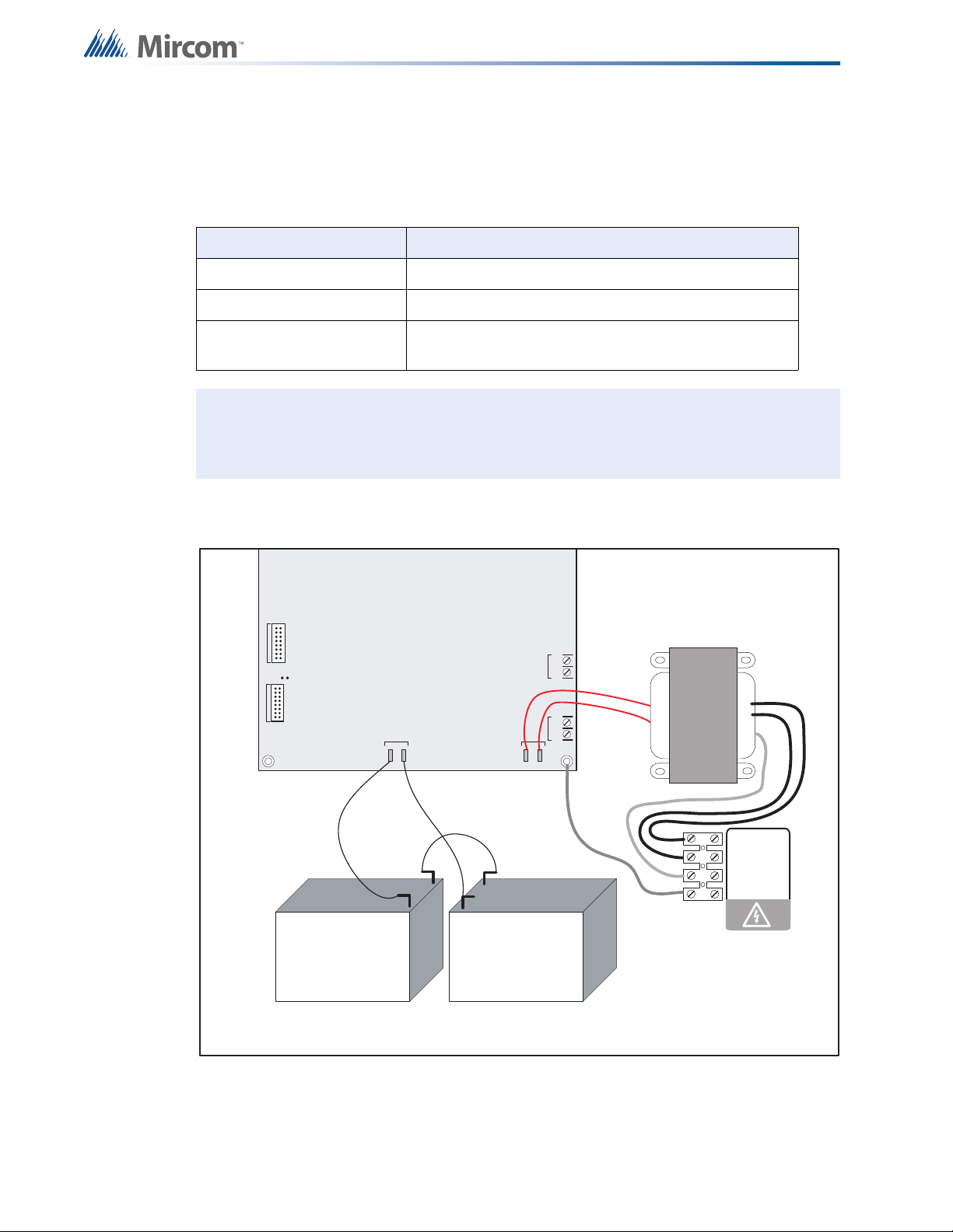
3. Connect the batteries as shown in Figure 27. Observe the correct polarity: the red wire is
positive (+) and black wire is negative (-).
MODU LE
TO RM-312/RM-306 RELAY
JW1
TO PR-300 MODULE
BATTERY
_
+
P3 P4
red
blk
red
red
P1 P2
SEC. TX
SIG 3SIG 4
Turning on the Panel
blk
-+-+
red
_
+
_
+
yellow
red
blk
green
240 VAC 50Hz
120 VAC 60Hz
N
GND
Battery Battery
NOTE : TO PREVENT SPARKING, CONNECT BATTERIES AFTER THE
SYSTEM MAIN A.C. POWER IS TURNED ON
Figure 27 Battery connections
All indicators should be off except for the green A.C. ON LED and the green TROUBLE
LED in the lower left corner of the main board.
Note: The green TROUBLE LED in the lower left corner of the main board is illuminated
when the system is normal. This LED is for diagnostics and indicates that the
Trouble Relay is in normal standby condition.
4. Configure the Fire Alarm Control Panel as described in "11.0 Configuration" on page 52.
40
Page 41

8.3 Troubleshooting
Table 5 Troubleshooting
Symptoms Possible Cause
When a circuit trouble occurs, its designated trouble indicator will be illuminated, as well
Circuit
Trouble
Remote Fail
Ground Fault
Battery
Trouble
as the Common Trouble LED and trouble buzzer. To correct the fault, check for open
wiring on that circuit, and check that the circuit is not disconnected or bypassed. For
information about bypassing and disconnecting, see sections , , and .
Note: Disconnecting a circuit will cause a system trouble (off-normal position).
Remote Fail is indicated on the main panel display for any failure reported by, or failure
to communicate with a remote annunciator or other remote device.
The panel has a common ground fault detector. To correct the fault, check for any
external wiring touching the chassis or other earth ground connection.
Check for the presence of batteries and their conditions. Low voltage (below 20.4 V) will
cause a battery trouble. If the battery trouble condition persists, replace the batteries as
soon as possible.
Turning on the Panel
Walk Test
Mode
Common
Trouble
If the LCD display indicates a walk test, the system is in walk test mode. See .
If only the Common Trouble LED is illuminated on the main panel and none of the
above trouble indicators are on, check the following for possible fault:
• Any missing interconnection wiring.
• Any missing module that was part of the configuration.
• Improperly secured cabling.
41
Page 42

9.0 Indicators, Controls and Operations
SYSTEM
RESE T
SIGNAL
SILENCE
FI RE
DRI LL
BUZZER
SILENCE
LAMP
TEST
1
4
7
*
2
5
8
0
3
6
9
#
ENTER
ME N U
CANCEL
INFO
ABC DEF
GHI JKL MNO
PRS
TUV
WXY
QZ
A.C. ON ALARM SUPV TRBL CPU FAIL
SYSTEM NORMAL
18:01 MON 2003-04-05
Refer to Figure 28 below which shows the LCD Display, the Keypad and Control Button
locations.
Figure 28 LCD Display and control buttons
The Main Display Panel on the Main Fire Alarm Control Board consists of:
• 5 common LED Indicators (under the LCD display)
• 5 Common Buttons (column left of key pad)
LED Indicators may be Amber, Red, or Green, and may illuminate continuously (steady), or at
one of two Flash Rates.
• Fast Flash (Supervisory)- 120 flashes per minute, 50% duty cycle
• Trouble Flash (Trouble)- 20 flashes per minute, 50% duty cycle
42
9.1 Common Indicators
9.1.1 Buzzer
The buzzer is activated by any of the following events:
Fire Alarm Steady
Supervisory Alarm Fast Flash
Trouble Trouble Flash Rate
Page 43

If the buzzer is turned on in response to a non-latching trouble or supervisory, it is turned off if
the condition causing it goes away and there is no other reason for it to be on.
9.1.2 A.C. ON LED
The green A.C. ON LED illuminates steadily as long as the main AC power is above minimum
level. The indicator turns off when the level falls below the power fail threshold and the panel is
switched to standby (battery) power.
9.1.3 Alarm LED
The red Alarm LED illuminates whenever the panel detects an alarm condition on any initiating
circuit. Since all alarms are latched until the panel is reset, the LED remains on until then.
9.1.4 Supervisory LED
The amber Supervisory LED turns on steady when there is a supervisory alarm in the Panel
caused by any latching or non-latching supervisory circuit. The LED is turned off when all nonlatching supervisory circuits are restored and there are no active latching supervisory circuits.
Latching supervisory alarms remain active until the Panel is reset.
Indicators, Controls and Operations
9.1.5 Trouble LED
The amber Trouble LED flashes at the trouble flash rate when the panel detects any trouble
condition. It turns off when all non-latching troubles are cleared.
9.1.6 CPU FAIL LED
The amber CPU FAIL LED Indicator flashes at the trouble flash rate to indicate a
microprocessor failure on the main board.
9.2 Common Controls
9.2.1 SYSTEM RESET Button
Press the SYSTEM RESET button to reset the Fire Alarm Control Panel and all circuits. In
particular, the SYSTEM RESET button does the following:
• Resets all latching trouble conditions
• Resets all initiating circuits
• Resets the 4-wire smoke supply
• Turns off all indicating circuits
• Turns off signal silence
• Turns off fire drill
• Stops and resets all timers
• Processes inputs as new events
• Does not affect Aux Disconnect
43
Page 44

9.2.2 SIGNAL SILENCE Button
12DET/4SIG LED UDACT
Version 1.7.8
Press the SIGNAL SILENCE button when the panel is in alarm to deactivate any silenceable
indicating circuits. Non-silenceable circuits are unaffected. Signals resound if there is a
subsequent alarm. Pressing SIGNAL SILENCE again resounds all silenceable signals. This
button does not function when the signal silence inhibit timer is running (see "6 Signal Silence
Inhibit timer" on page 56). It also does not function if the indicating circuits are active as the
result of a fire drill.
9.2.3 FIRE DRILL Button
The FIRE DRILL button activates all non-disconnected (un-bypassed) indicating circuits, but
does not transmit any alarms via the city tie, Common Alarm Relay or Auxiliary Alarm Relay.
The fire drill activates the signals in the evacuation code programmed. For example, if the
evacuation code is set to Temporal Code, the signals will be pulsed on for 0.5 seconds, off for
0.5 seconds in rounds of 3 and then pause for 1.5 seconds and repeat.
The fire drill is canceled by pressing the button again, or if the panel goes into a real alarm.
9.2.4 LAMP TEST Button
Indicators, Controls and Operations
Press the LAMP TEST button to make the front panel indicators steadily illuminate (except for
CPU FAIL) and to turn the buzzer on steady. If the lamp test is active for more than 10
seconds, the Common Trouble is activated.
Press and hold the LAMP TEST for 3 seconds to show the information about the system and
the firmware version as shown below.
Figure 29 Lamp test
The first line shows the number of zones and panel type and the second line shows the
software version number.
9.2.5 BUZZER SILENCE Button
Press the BUZZER SILENCE button while the buzzer is sounding to silence the buzzer. The
buzzer resounds if there is a subsequent event. Pressing the button when the buzzer is not
sounding has no effect.
9.3 Common Relays
9.3.1 Common Alarm Relay
The Common Alarm Relay (labeled ALARM RELAY on the circuit board) activates when a
general alarm sequence is activated. Since all alarm conditions are latched until system reset,
the relay remains on until the alarm is cleared and the system is reset. The Common Alarm
Relay can be disconnected by “Aux Disconnect” (see "Aux. Disc. (Command Menu)" on
page 75) if programmed to do so (see "Table 7 Feature Config menu" on page 56.
44
Page 45

9.3.2 Common Supervisory Relay
i
i
The Common Supervisory Relay (labeled SUPERVISORY RELAY on the circuit board)
activates when the common supervisory sequence is activated as the result of an alarm or any
un-bypassed latching or non-latching supervisory circuit. The relay is turned off if all nonlatching supervisory circuits are restored and there are no latching supervisory circuits active.
The relay can be disconnected by “Aux Disconnect” (see "Aux. Disc. (Command Menu)" on
page 75) if programmed to do so (see "Table 7 Feature Config menu" on page 56). This
Common Supervisory Relay will function the same way as a Common Alarm Relay if
programmed to (see "12 Common Supervisory Relay" on page 57).
9.3.3 Common Trouble Relay
The Common Trouble Relay (labeled TROUBLE RELAY on the circuit board) is activated
when the common trouble sequence is activated as the result of the trouble condition being
detected on the system. It is turned off when all troubles are cleared.
Note: Some troubles are latching: once they are detected they remain active until
system reset. In this case the Common Trouble LED will also remain active until
system reset. The common trouble is not bypassed by the Auxiliary Disconnect
function.
Indicators, Controls and Operations
9.3.4 Auxiliary Alarm Relay
The Auxiliary Alarm Relay (labeled AUX. RELAY on the circuit board) functions the same way
as the Common Alarm Relay in every respect except that it can be disconnected by “Aux
Disconnect” (see "11.16 Aux. Disc. (Command Menu)" on page 75) with or without correlated
relays if it is programmed to do so (see "Table 7 Feature Config menu" on page 56). When
configured, the relay can also be disconnected if signal silence is active and reconnected if
signal silence is de-activated.
Note: Each relay has an LED beside it. These LEDs are used for diagnostic purposes.
9.4 Circuit Types
9.4.1 Initiating (Detection) Circuit Types
9.4.2 Non-Verified Alarm
A non-verified alarm can have pull stations, smoke detectors, or heat detectors attached to it.
Activation of any of these devices will immediately result in an alarm condition in the Fire
Alarm Control Panel. An alarm condition causes the Common Alarm LED to illuminate red.
9.4.3 Verified Alarm
Verified alarms are verified by a reset and timing procedure, and may include smoke
detectors, heat detectors or pull stations. Activation of pull stations or heat detectors results in
an alarm condition in the Fire Alarm Control Panel within four seconds. Smoke detectors are
verified for a real alarm within 60 seconds, depending upon the startup time of the devices
45
Page 46

being used. If four seconds is too long a response time for pull stations, then wire them
i
i
separately on a non-verified alarm circuit. An alarm condition causes the Common Alarm LED
to illuminate red.
9.4.4 Sprinkler Alarm (for Sprinkler Flow Sensors)
Sprinkler alarms are identical to normal non-verified alarms unless water flow retard operation
is enabled. If water flow retard operation is enabled, then these circuits are sampled every one
second. If ten samples are active within any 15-second interval, the sprinkler alarm is
confirmed and processed. An alarm condition causes the Common Alarm LED to illuminate
red.
Note: Do not use retard operation with any external retarding device; maximum retard
may not exceed 120 seconds.
9.4.5 Water Flow Alarm (Water Flow Sensors)
Water flow alarms are identical to normal non-verified alarms except that any indicating
circuits programmed to these circuits (all are by default) are non-silenceable. Also, if water
flow retard operation is enabled (see "4 Waterflow/Sprinkler Retard Operation" on page 56),
these circuits are sampled every one second. If ten samples are active within any 15-second
interval, the water flow alarm is confirmed and processed. An alarm condition causes the
Common Alarm LED to illuminate red.
Indicators, Controls and Operations
Note: Do not use retard operation with any external retarding device; maximum retard
may not exceed 120 seconds.
9.4.6 Non-Latching Supervisory (For Supervisory Circuits)
An activation on these circuits causes the amber Common Supervisory LED to illuminate. The
buzzer sounds at the fast rate. If the circuit activation is removed, the supervisory condition
clears (as long as there are no other supervisory conditions in the system) and the SUPV LED
turns off.
9.4.7 Latching Supervisory (For Supervisory Devices)
An activation on these circuits causes the amber Common Supervisory LED to illuminate. The
buzzer sounds at the fast rate. If the circuit activation is removed, the supervisory condition
does NOT clear.
9.4.8 Monitor
This is a supervised general-purpose non-latching input used mainly for correlating to a relay
circuit. No other system condition occurs as a result of its activation (short circuit), although it
is supervised for trouble (open circuit).
46
Page 47

9.4.9 Trouble-Only
The Trouble-Only circuit monitors a Trouble condition from an external device such as QX5000 Audio System. An activation of a Trouble-Only circuit causes the TRBL LED to flash at
the Trouble rate. Both open and short circuits generate a non-latching Trouble condition.
9.4.10 Indicating (Signal) Circuit Types
9.4.11 Silenceable Signal
The silenceable signal circuit is used for audible devices such as bells and piezo mini-horns
that may be silenced either manually or automatically. While sounding, these devices follow
the pattern appropriate for the condition: the configured Evacuation Code (the default is
Temporal Code) during alarm (see "9.5 Evacuation Codes" below).
9.4.12 Non-Silenceable Signal
The Non-Silenceable Signal circuit is used for audible devices such as bells and piezo minihorns that may not be silenced either manually or automatically. While sounding, these
devices follow the pattern appropriate for the condition: the configured Evacuation Code (the
default is Temporal Code) during alarm (see "9.5 Evacuation Codes" below).
Indicators, Controls and Operations
9.4.13 Silenceable Strobe
Silenceable Strobes are silenced when the SIGNAL SILENCE button is pressed. For
synchronous strobes see "10.0 Supported Protocols and Devices" on page 50. (Note: Strobes
do not support any code pattern.)
9.4.14 Non-Silenceable Strobes
Non-Silenceable Strobes are not silenced when the SIGNAL SILENCE button is pressed. For
synchronous strobes see section "10.0 Supported Protocols and Devices" on page 50. (Note:
Strobes do not support any code pattern.)
47
Page 48

9.5 Evacuation Codes
0.5s
0
.
5
s
1.5s
0.5s
0
.
5
s
5s 10s
CON T INO U S
TEMPORA L CODE
MARCH CODE
CA LIF OR N IA CO D E
0.5s
0
.
5
s
1.5s
0.5s
0
.
5
s
5s 10s
CONTINUOUS
TEMPORAL CODE
MARCH CODE
CALIFORNIA CODE
Continuous On 100% of the time
Temporal Code 3 of 0.5 second on, 0.5 second off, then 1.5 second pause
March Code 0.5 second on, 0.5 second off
California Code 5 seconds on, 10 seconds off
Indicators, Controls and Operations
Figure 30 Evacuation Codes
9.6 Fire Alarm Operation
In a basic system, all alarm inputs are treated in a similar manner. Alarm inputs include any of
the following: non-verified alarm, verified alarm, sprinkler alarm, and water flow alarm. If any of
these alarm inputs occur when the panel is not already in alarm, the following occurs:
• The buzzer sounds steadily
• If the fire drill is active, it is cancelled
• The Common Alarm Indicator (the ALARM LED) turns on
• The Auxiliary Alarm Relay activates if Aux. Disconnect is not active
• The auto Signal Silence Timer, if configured, starts
• The Signal Silence Inhibit Timer, if configured, starts
• All connected relays programmed to the input are activated (provided that Aux
Disconnect is not active)
• Non-disconnected strobes associated with the input are activated
• Non-disconnected signals associated with the input are activated at the evacuation rate
Subsequent alarms when the panel is already in alarm cause the following:
48
• The buzzer sounds steadily
Page 49

Indicators, Controls and Operations
• If signals have been silenced as a result of the SIGNAL SILENCE button or the Auto
Signal Silence Timer, the signals resound and the Auto Signal Silence Timer, if
configured, is restarted
• Any additional non-disconnected strobes associated with the new input are activated
continuously
• Any additional non-disconnected signals associated with the new input are activated at
the evacuation rate
49
Page 50

10.0 Supported Protocols and Devices
i
10.1 Synchronous Strobes
The synchronous strobe models that are supported by the FA-300 panel include Mircom
models FHS-240 and FS-240. A separate compatibility list is available for different supported
models.
Strobes can be configured as normal (not synchronized). See . Any selection made is systemwide (that is, the selection applies to all the circuits in the system that are configured as
strobes).
10.2 Signal silence on strobes
The signal silence action on strobes depends on the configuration.
10.2.1 Non-silenceable strobes
If the output zone is configured as non-silenceable strobe and the SIGNAL SILENCE button is
pressed while the strobes are active, only the horns are silenced. If SIGNAL SILENCE is
deactivated, then the horns turn back on.
10.2.2 Silenceable strobes
If the output circuit is configured as silenceable strobe, and if the SIGNAL SILENCE button is
pressed, both the horn and strobe are turned off. Pressing the SIGNAL SILENCE button again
turns them on again.
Note: Please see the strobe manufacturer’s data for details.
10.3 System Sensor’s i3 Devices
The FA-300 fire control panel supports System Sensor’s i3 devices. Only the two wire smoke
detectors 2W-B and 2WT-B are supported on the i
fixed temperature (135°F / 57.2°C) thermal detector and is capable of sensing a freeze
condition if the temperature is below 41°F / 5°C.
The zones should be programmed to i
is not programmed as an i
regular zone. The panel can detect multiple troubles; if different devices have different troubles
on the same zone, all troubles are reported. The following troubles are reported for a zone
configured as an i
3
zone.
3
zone and i3 devices are connected to the zone, it is treated as a
3
devices to be considered as i3 zone (see ). If the zone
3
zone. Model 2WT-B features a built-in
10.3.1 Open circuit trouble
If the circuit is broken, the panel shows an open trouble. The panel can still communicate with
the devices depending upon where the open occurs.
50
Page 51

10.3.2 Communication Trouble
Zone-1
Open Trb. 1/ 1
Zone-1
Communic. Trb 1/ 1
Zone-1
Dirty Dev. Trb 1/ 1
Zone-1
Out of Sens Trb 1/ 1
Zone-1
Freeze Trb. 1/ 1
If there is a fault in the line or the line is too noisy, the panel cannot communicate with the
devices. In this case, the panel shows a communication trouble.
10.3.3 Dirty Device trouble
If any of the devices on the i3 zone are dirty, the panel shows a dirty device trouble. The device
must be cleaned or must be replaced with a new device.
Supported Protocols and Devices
10.3.4 Out of sensitivity trouble
If any of the devices on the i3 zone are out of sensitivity and cannot detect an alarm condition,
the panel shows an out of sensitivity trouble. In this case, the device is not usable and should
be replaced.
10.3.5 Freeze trouble
If the device has detected a freeze condition (below 41°F / 5°C), then the panel shows a
freeze trouble. This works with model 2WT-B only. Model 2W-B does not indicate a freeze
trouble.
The LEDs on the i
Table 6 i
i3 Detector Condition
Power-up Blinks every 10 sec Blinks every 10 sec
Normal (Standby) Blinks every 5 sec Off
Out of sensitivity (defective or dirty) Off Blinks every 5 sec
Freeze trouble Off Blinks every 10 sec
Alarm Off Solid
3
smoke detectors provide a local visual indication of the detector status.
3
detector LEDs
Green LED Red LED
51
Page 52

11.0 Configuration
SYSTEM
RESET
SIGNAL
SILENCE
FI RE
DRI LL
BUZZER
SILENCE
LAMP
TEST
1
4
7
*
2
5
8
0
3
6
9
#
ENTER
ME N U
CANCEL
INFO
ABC DEF
GHI JKL MNO
PRS
TUV
WXY
QZ
A.C. ON ALARM SUPV TRBL CPU FAIL
SYSTEM NORMAL
18:01 MON 2003-04-05
There are three methods of configuring the FA-300 LCD Series Fire Alarm Panels:
• Direct configuration using the main LCD display and the menu buttons.
• Using a PC or laptop computer with a UIMA adapter.
• Using a PC or laptop computer with remote connection (must use fire alarm with built-in
UDACT).
This chapter explains how to configure an FA-300 LCD Series Fire Alarm Panel using the
main LCD display.
The front panel display is shown in Figure 31.
Figure 31 FA-300 main LCD display
52
Page 53

11.1 Accessing Configuration Mode
Enter passcode
_
i
To access configuration mode
1. Press the Menu button on the front panel display.
2. Enter your passcode.
The minimum number of digits for the passcode is four and the maximum is ten. The
passcode must be numerical values only. The default passcode is 1111.
3. Press the ENTER button.
The main command menu appears.
If the passcode is wrong, the system prompts you to re-enter the passcode. After three
tries the system takes you back to the normal message display.
Figure 32 Enter passcode
Configuration
11.2 Command Menu
The command menu is shown in Figure 33. The first line of the LCD always displays
-Command Menu-, and the second line scrolls through different selections.
To scroll through the menu
• Use the up and down arrow buttons, and then press the ENTER button to make a
selection.
To exit from the command menu
• Select the Exit menu option, and then press the ENTER button.
Note: Close jumper JW5 on the main board to access Command Menu features 1 and
9.
53
Page 54

Configuration
-Command Menu-
1. FA-300 Config
2. Config Info
3. Set Time
4. Set Password
5. View EventLog
6. Clear EventLog
7. Walk Test
8. I3 Loop test
9. Dialer Config
10.Test Dialer
11.Bypass Det Ckt
12.Bypass NAC Ckt
13.Aux Disc
14.Exit
Figure 33 Command Menu
11.2.1 Using the Keypad to Program the FA-300
1. Access the configuration mode as described in "11.1 Accessing Configuration Mode"
2. Press ENTER to select an option.
3. Press the up and down arrow buttons to scroll through the menu.
4. Press ENTER to select an option.
5. Press the left or right arrow buttons to select or unselect an option (selected = X). Use
6. Once you have made the correct selection, press ENTER to confirm the change.
7. Press CANCEL to return to the previous menu.
above.
The corresponding menu appears.
the up and down arrows to scroll through the different options.
54
Page 55

11.3 Panel Config (Command Menu)
1. Features
2. Inp Zone
3. I3 Zone
4. Opt. Zone
-FA-300 Config-
5. Correlation
6. Inp Zone Label
7. Opt Zone Label
8. Default Config
1 Man. Sig. Sil.
2 Fire Drill
16 Active EOL
- Feature Config -
3 Opt. Ckt. Corr
4 Wtr/Sprk. Retd
5 Aux Disc Prog
6 Sig-Sil Inh Tmr
15 Signal Rate
9 Rem. Annun.
10 Alm. Xmit-Sil.
8 Auto Sil. Tmr
11 Pwr Fail Tmr.
12 Com. Supv. Rly
13 Sig-Sil. Isol.
14 Strobe Type
7 Aux Dis Alm&Sv
The FA-300 configuration menu is shown in Figure 34.
Figure 34 FA-300 Config menu
Configuration
11.4 Feature Config
Select Features to access the Feature Config menu shown in Figure 35.
Figure 35 Feature Config menu
55
Page 56

Table 7 describes the options in the Feature Config menu.
Manual Sig. Silence
[X] ENABLE
Fire Drill
[X] ENABLE
Opt. Ckt. Corr.
[X] DISABLE
Waterflow/Sprk. Retd
[X] DISABLE
Aux Disc Prog
[X] DISABLE
Sig-Sil. Inhibit Tmr
[X] DISABLE
Table 7 Feature Config menu
Configuration
Feature Default
1 Manual Signal Silence
[X] ENABLE->Default
[ ] DISABLE
Command Menu - FA-300 Config - Features
2 Fire Drill
[X] ENABLE ->Default
[ ] DISABLE
Command Menu - FA-300 Config - Features
3 Output Circuit Correlation
[X] DISABLE ->Def
[ ] ENABLE
Command Menu - FA-300 Config - Features
4 Waterflow/Sprinkler Retard
Operation
[X] DISABLE ->Def
[ ] ENABLE
Command Menu - FA-300 Config - Features
5 “Aux. disconnect” disconnects
Auxiliary Alarm Relay and all
correlated relays
Command Menu - FA-300 Config - Features
6 Signal Silence Inhibit timer
[ ] ENABLE
[X] DISABLE->Default
[X] DISABLE->Default
[ ] 10 SEC
[ ] 20 SEC
[ ] 30 SEC
[ ] 1 MIN
Name in the
Configuration Utility
Manual signal silence
Fire drill
Signal correlations
Retard waterflow and
sprinkler circuit
"Aux Disconnect"
disconnects prog.
relay
Signal silence inhibit
FA-300
Description
Use this function to enable or
disable the SIGNAL SILENCE
button. See "9.2.2 SIGNAL
SILENCE Button" on page 44.
Use this function to enable or
disable the FIRE DRILL button.
See "9.2.3 FIRE DRILL
Button" on page 44.
If enabled, the programmed
correlations (see section
11.4.4 on page 60) are
effective. If disabled, the
programmed correlations are
ignored and all the output
circuits are correlated to all the
input circuits.
If disabled, all the initiating
circuits configured as water
flow or sprinkler act as nonverified alarms. If enabled,
retard operation is performed
for initiating circuits configured
as water flow or sprinkler.
See "9.4.5 Water Flow Alarm
(Water Flow Sensors)" on
page 46.
If enabled, the Auxiliary Alarm
Relay and all correlated relays
are disconnected when you
select “Aux Disconnect” (see
page 75). Correlated relays
include: RM312/RM306 relays
and SRM-312 relays.
If disabled, only the Auxiliary
Alarm Relay is disconnected
when you select “Aux
Disconnect” (see page 75).
Use this function to inhibit the
SIGNAL SILENCE button for a
desired length of time. While
this timer is running, pressing
the SIGNAL SILENCE button
has no effect. See "9.2.2
SIGNAL SILENCE Button" on
page 44.
56
Page 57

Table 7 Feature Config menu
Aux Dis,Dis Alm&Spv
[X] DISABLE
Auto Sig-Sil. Timer
[X] DISABLE
No. of Remote Annun.
[X] NONE
Alm. Xmit-Sil.
[X] DISABLE
AC Pwr Fail Dly Tmr.
[X] NONE
Common Supv. Relay
[X] ENABLE
Configuration
Feature Default
Command Menu - FA-300 Config - Features
7 “Aux. disconnect” disconnects
Common Alarm Relay and
Common Supervisory Relay
[ ] ENABLE
[X] DISABLE->Default
Command Menu - FA-300 Config - Features
8 Auto Signal Silence Timer
Command Menu - FA-300 Config - Features
9 Number of Remote
Annunciators or smart relays
Command Menu - FA-300 Config - Features
[X] DISABLE->Default
[ ] 5 Min
[ ] 10 Min
[ ] 15 Min
[ ] 20 Min
[ ] 30 Min
[X] NONE->Default
[ ] 1
[ ] 2
[ ] 3
[ ] 4
[ ] 5
[ ] 6
10 Silence Alarm transmit
[X] DISABLE ->Def
[ ] ENABLE
Name in the
Configuration Utility
"Aux Disconnect"
disconnects alarm
relay
Signal silence
Remote Annunciators
Alarm transmit
affected by signal
silence
FA-300
Description
If enabled, the Common Alarm
Relay and the Common
Supervisory Relay, in addition
to the Auxiliary Alarm Relay,
are disconnected when you
select “Aux Disconnect” (see
page 75). The PR-300 will not
transmit a supervisory or alarm
event.
If disabled, selecting “Aux
Disconnect” (see page 75) has
no effect on the Common Alarm
Relay, the Common
Supervisory Relay, and the PR-
300.
Use this function to determine
the time period for which the
indicating circuits sound before
they are automatically silenced.
Use this function to select the
number of Remote
Annunciators. Any combination
of Remote Annunciators or
smart relays can be used as
long as the total number does
not exceed 6. The
Annunciators’ addresses
should be without gaps and in
sequence.
If disabled, the SIGNAL
SILENCE button does not
silence the Auxiliary Alarm
Relay, but it does silence the
indicating circuits. If enabled,
the SIGNAL SILENCE button
silences the Auxiliary Alarm
Relay and the indicating
circuits. See "9.2.2 SIGNAL
SILENCE Button" on page 44.
Command Menu - FA-300 Config - Features
11 AC power fail delay timer
Command Menu - FA-300 Config - Features
12 Common Supervisory Relay
[X] NONE ->Default
[ ] 1 HRS
[ ] 2 HRS
[ ] 3 HRS
[X] ENABLE ->Default
[ ] DISABLE
Supervisory relay used
as alarm relay
Use this function to delay the
AC power fail trouble for the
programmed time period. If
disabled, the AC power fail is
reported right away.
If enabled, the Common
Supervisory Relay behaves as
a common alarm relay. If
disabled, it behaves as a
common supervisory relay.
57
Page 58
Table 7 Feature Config menu
Sig-Sil. Isolator
[X] DISABLE
Strobe Type
[X] NORMAL
Signal Rate
[X] TEMPORAL
Active EOL
[X] DISABLE
Configuration
Feature Default
Command Menu - FA-300 Config - Features
13 Signal Isolators
[ ] ENABLE
[X] DISABLE ->Def
Command Menu - FA-300 Config - Features
14 Strobe Type
Command Menu - FA-300 Config - Features
15 Signal rate (Evacuation code)
[X] NORMAL ->Default
[ ] MIRCOM
[ ] FARADY
[ ] WHEELOCK
[ ] GENTEX
[ ] SYSTEM SENSOR
[X] TEMPORAL->Def
[ ] CONTINOUS
[ ] MARCH TIME
[ ] CALIFORNIA
Name in the
Configuration Utility
Isolators on signal
circuits
Strobe
Signal rate
FA-300
Description
Enable this function only when
suite isolators are used
(Canada only).
Use this menu to select the
manufacturer of the strobes
used in the system. The
selection is system-wide and
applies to all indicating circuits
configured as strobes. For
NORMAL strobes there is no
synchronization, while other
strobes use the manufacturer’s
protocol to synchronize the
strobes.
Use this function to set the rate
at which the indicating circuits
sound.
Command Menu - FA-300 Config - Features
16 Active EOL
[X] DISABLE->Default
[ ] ENABLE
Active end-of-line
Enable this function if you are
using an active end-of-line
resistor. Enable this function if
you are using the ICAC-306
(the ICAC-306 has built in
active end-of-line resistors).
58
Page 59

Command Menu - FA-300 Config
1 Zone-1
2 Zone-2
--
--
Initiating Zone
12 Zone12
Zone-1 Type
[X] NON-VERIF ALARM
Zone-12 Type
[X] NON-VERIF ALARM
[ ] Zone-1
[ ] Zone-2
--
--
I3 Detection Zones
[ ] Zone-12
11.4.1 Inp Zone
Command Menu - FA-300 Config - Ipt. Zone
1. Type (Initiating circuit)
12.
[X] NON-VERIF ALARM >Default
[ ] VERIF ALARM
[ ] SPRKL ALM
[ ] WTR-FLOW ALM
[ ] NON-LATCH SUP
[ ] LATCH SUPV
[ ] GEN ALARM
[ ] BUILDING
[ ] TRB ONLY
Configuration
Use this menu to select the
circuit type of each input
zone. See "9.4 Circuit
Types" on page 45.
Command Menu - FA-300 Config
11.4.2 i3 Zone
[ ] Zone-1->Default
.
.
.
[ ] Zone-12->Default
3
Use this function if i
devices are present on a
zone. See "10.3 System
Sensor’s i3 Devices" on
page 50.
59
Page 60

Command Menu - FA-300 Config
1 NAC-1
2 NAC-2
3 NAC-3
4 NAC-4
Indicating Zone
NAC-1 Type
[X] SIL-ABLE
NAC-4 Type
[X] SIL-ABLE
Zone-1 Corr.
[X] NAC-1
Zone-12 Corr.
[X] NAC-1
1 Zone-1
2 Zone-2
--
--
Initiating Zone
12 Zone12
11.4.3 Opt Zone
Command Menu - FA-300 Config - Opt. Zone
1. Type (Indicating Circuits)
Configuration
4.
Command Menu --> FA-300 Config
11.4.4 Correlation
Command Menu - FA-300 Config Correlation
1.Correlation
12.
[X] SIL-ABLE->Default
[ ] NON SIL-ABLE
[ ] SIL-ABLE STR
[ ] NON-SIL STR
[X] NAC-1 ->Default
[X] NAC-2 ->Default
[X] NAC-3 ->Default
[X] NAC-4 ->Default
Use this menu to select the
circuit type of each
indicating circuit. See
"9.4.10 Indicating (Signal)
Circuit Types" on page 47.
Use this menu to correlate
initiating circuits to
indicating circuits. By
default all the initiating
circuits are correlated to all
the indicating circuits.
Command Menu --> FA-300 Config
11.4.5 Inp Zone Label
60
Page 61

Use the keypad described below for entering a message.
Zone-1 Label
Zone-1
Zone-12 Label
Zone-12
1 NAC-1
2 NAC-2
3 NAC-3
4 NAC-4
Indicating Zone
NAC-1 Label
NAC-1
NAC-4 Label
NAC-4
Command Menu - FA-300 Config - Ipt. Zone
Label
1.Initiating zone label
12.
Configuration
[Zone-1 ]->Default
[Zone-12 ]->Default
KEYPAD TRANSLATION AS MARKED ON THE KEYS
SEQ refers to the number of times the key must be pressed
to display the number or letter.
KEY SEQ 1 2 3 4 KEY SEQ 1 2 3 4
--------------------------------------
Key #1 1
Key #2 2 A B C Key #3 3 D E F
Key #4 4 G H I Key #5 5 J K L
Key #6 6 M N O Key #7 7 P R S
Key #8 8 T U V Key #9 9 W X Y
Key #0 0 Q Z Key * Backspace
Key # Forward
Press the ENTER button to input the message.
Command Menu --> FA-300 Config
11.4.6 Opt Zone Label
Follow the instructions below to enter a message.
Command Menu - FA-300 Config - Opt. Zone
Label
1.Indicating zone label
4.
[NAC-1 ]->Default
[NAC-4 ]->Default
KEYPAD TRANSLATION AS MARKED ON THE KEYS
SEQ refers to the number of times the key must be pressed
to display the number or letter.
KEY SEQ 1 2 3 4 KEY SEQ 1 2 3 4
--------------------------------------
Key #1 1
Key #2 2 A B C Key #3 3 D E F
Key #4 4 G H I Key #5 5 J K L
Key #6 6 M N O Key #7 7 P R S
Key #8 8 T U V Key #9 9 W X Y
Key #0 0 Q Z Key * Backspace
Key # Forward
Press the ENTER button to input the message.
61
Page 62
Command Menu --> FA-300 Config
Load the default
settings? Y
Default settings
have been loaded
Configuration type:
Factory default
Job Name:
No job loaded
Technician ID:
Unknown
Cfg. Date and Time:
hh:mm day year:mm:dd
Cfg. Tool S/W Vers.:
Version:x.x.x.x
11.4.7 Default Configuration
Configuration
Press the up and down arrow buttons to
select between Y/N. Press ENTER to restore
the default configuration.
Use this menu to load the default configuration in the panel.
Warning: When you load the default configuration, the
previously programmed configuration is lost permanently.
11.5 Config. Info. (Command Menu)
Configuration type shows how the panel was configured.
Factory default means the panel has not been configured;
it is as it came from the factory.
Front Panel means it was configured at the panel.
Serial Port means the configuration was done from a
Press the down arrow button to see more
information.
computer through the serial port.
Modem means the configuration was done remotely
through a modem.
If you upload a job to the panel using the FA-300
Configuration Utility, the job name appears on this screen.
The job name can be up to a maximum of 20 characters.
Press the down arrow button for further
information.
Press the down arrow button for further
information.
If you upload a job to the panel using the FA-300
Configuration Utility, the technician’s name (ID) appears on
this screen. The technician ID can be up to a maximum of
10 characters.
This screen shows the date and time that the configuration
was last changed.
This screen shows the version of the FA-300 Configuration
Utility. It displays 0.0.0.0 if the FA-300 Configuration Utility
was not used.
62
Page 63

11.6 Set Time (Command Menu)
1 Daylight Save
2 Time Clock
3 Compensation
Daylight Saving
[X] DISABLE
HH:MM WKD YYYY-MM-DD
00:00 MON 2000-01-01
Daily Compensation:
0
Daily Compensation:
Panel Config Updated
Command Menu - Set Time
Configuration
11.6.1 Daylight Saving
Command Menu - Time Clock
11.6.2 Time Clock
Command Menu - Time Clock
11.6.3 Compensation
Once the compensation value is entered the
display will be:
[X] DISABLE ->Default
[ ] ENABLE
Default
00:00 MON 2000-01-01
Compensation value
can range from -15 to
+15 seconds.
Use this menu to enable
daylight savings time.
Use this menu to set the
time and date. Use the left
and right arrow buttons to
move the cursor to the
desired location in the
display and use the up and
down arrow buttons to
increase or decrease the
values. Press the ENTER
button to accept the
changes and the CANCEL
button to ignore the
changes.
Note: The time is in 24 hour
format.
Use the up and down arrow
buttons to select the daily
compensation value and
press ENTER. For a fast
clock adjust negatively. For
a slow clock adjust
positively. For example, for
a clock which runs 5
minutes a month (based on
30 days) fast, select -10
seconds.
63
Page 64
11.7 Set Password (Command Menu)
Enter new passcode
[ ]
Re-enter passcode
[ ]
invalid passcode
Passcode updated
EAST LOBBY ENTRANCE
OPEN TRB 01/09
VERIFIED ALARM Z-01
2002/10/22 11:45.AM
ZONE
Message
EVENT
01 of 09
Process
Type
Physical
Zone No.
DATE
TIME
"INFO " Key
EVENT
type
ZONE
Message
EVENT
type
“INFO” KEY
Process
Type
Physical
Zone No.
Time
If the passcode does not match, the following
message appears.
If the passcode is OK the following message
appears.
1111 -> Default
Configuration
Use this menu to change
the passcode. The minimum
number of digits is 4 and the
maximum number is 10.
Only numeric digits are
allowed.
11.8 View EventLog (Command Menu)
The event log looks the same as the normal event queue (see "11.18 Zone messages" on
page 75). Press the INFO button to see more information about the event. Figure 36 shows an
example of how the INFO button works.
Figure 36 The event log
The event log saves a maximum of 200 events.
64
Page 65

11.9 Clear EventLog (Command Menu)
-Select Log-
1 Alarm Log
2 General Log
3 All Logs
Clear all the
selected log(s)? Y
Log(s) cleared
Perform the
walk test? Y
-WALK TEST ZONES-
[ ] Zone-1
-Walk test active-
Alarm:00 Trb:00
Select the type of log to clear. Press the
ENTER button. The system confirms before
clearing logs.
Press the ENTER button to confirm or the
CANCEL button to cancel the operation.
Use this menu to clear alarm logs, general logs, or both.
Configuration
11.10 Walk Test (Command Menu)
A walk test allows an installer to verify the initiating circuit wiring in a system. When walk test is
selected, the following screen appears:
Figure 37 Walk test confirmation
Press the ENTER button to activate the walk test and the CANCEL button to cancel the walk
test. The next screen will allow zones to be selected for walk test. Use the up and down arrow
buttons to scroll through the zones and use the left and right arrow buttons to select a zone.
Press the ENTER button when you are done with all the selections.
Figure 38 Walk test zones
The walk test is now active (see Figure 39).
Figure 39 Walk test active
The activation of any initiating circuit that has been selected for a walk test will cause the
audible indicating circuits (not strobes) to activate briefly for a number of short bursts
corresponding to the selected circuit number. If the first selected circuit is activated, the
65
Page 66

Configuration
i
Perform the i3
Loop test? Y
-I3 TEST ZONES-
[ ]Zone-1
indication circuits sound for one burst. If the second selected circuit is activated, the indication
circuits sound for two bursts, and so on. This means that if, for example, circuits 1, 3 and 5 are
selected for the walk test, the indicating circuits sound with one, two and three bursts
respectively. The burst interval is half a second ON and half a second OFF. After the sounding
pattern is sent to the indicating circuits, the initiating circuit is reset and tested again. If it is still
active (in alarm) the pattern is re-sent. Trouble on any initiating circuit selected for the walk test
activates the indicating circuits continuously for five seconds. Activation of a circuit also
causes the alarm count to increase while the trouble on the initiating circuit causes the trouble
count to increase.
Alarm Verification and Water flow Alarm Retard Operations are disabled on circuits being walk
tested. All circuits not selected for the walk test continue to function normally. If a circuit was
disconnected before the walk test mode was entered and is not selected for the walk test, it
remains disconnected while the walk test is active. Walk test operation is disabled if the Fire
Alarm Control Panel is in alarm or goes into alarm while the walk test is active.
Notes: If a UDACT is used with the system, all walk test events are reported to the
monitoring agency. The monitoring agency should be instructed to ignore
reported events during the walk test.
IF THERE IS NO ACTIVITY FOR ONE HOUR, THE SYSTEM RETURNS TO
NORMAL OPERATION.
11.11 I3 Loop Test (Command Menu)
The i3 maintenance test is designed to test the devices on the i3 zone. If there is noise on the
line or if the device is too far away from the panel, the devices may not respond to the panel
3
inquiries. An i
just been powered up or reset, wait six minutes before selecting the i
test is selected, the following message appears on the screen:
Figure 40 i
If you select “yes” by pressing “ENTER”, the display will ask you for which zone you want to
perform the i
zone by pressing the “UP” and “DOWN” keys and then pressing the “RIGHT” key to select the
device. After the device is selected press “ENTER”.
maintenance test can be invoked from the command menu. If the fire alarm has
3
loop test confirmation
3
test. Note that only one zone at a time can be in maintenance test. Select the
3
loop test. If the i3 loop
66
Figure 41 i
3
test zones
Page 67

Configuration
The selected zone
is not ready yet
The selected zone
is not i3 type
i
1 Account Info
2 Telephone line
3 Report Options
4 Time Parameter
-Dialer Config-
5 Enable/Disable
6 Ring Detect
If the i3 maintenance test is selected within six minutes after power-up or reset, the following
information message is displayed.
Figure 42 i
If a zone is selected that is not configured as an i
Figure 43 The selected zone is not i
When the zone goes into the i
maintenance test takes five minutes. During this time you can walk through the device and
make sure all the devices are working properly. The following table lists the status of the
devices while in loop test.
Note: Out of sensitivity can mean the device is dirty.
i3 Detector Condition
Proper operation Double blink every 5 sec OFF
Out of sensitivity OFF Double blink every 5 sec
Freeze condition OFF Double blink every10 sec
3
test not ready
Table 8 i
3
zone, the following message is displayed:
3
type
3
loop test, no other zone can be put into the test. The
3
Detector LEDs while in test mode
Green LED Red LED
11.12 Dialer Config (Command Menu)
You can cancel the maintenance test either by pressing the RESET button or by going into the
configuration section and canceling the test.
Figure 44 shows the dialer configuration menu.
Figure 44 Dialer Config menu
67
Page 68

Command Menu-->Dialer Config
1 Account#1 ID
2 Account#1 Tel
3 Accnt#1 Format
4 Account#2 ID
- Account Info -
5 Account#2 Tel
6 Accnt#2 Format
Account#1 ID:
_
Account#1 Telnum:
_
ACCNT#1 Format:
[X] Contact ID
11.12.1Account Info
Figure 45 Account Info menu
Configuration
Command Menu - Dialer Config - Account
Info
Account #1 Identification
Command Menu - Dialer Config - Account
Info
2.Account #1 Telephone Number
Command Menu - Dialer Config - Account
Info
3.Account #1 Reporting Format
123456->Default
[ 101 ]->Default
[X] CONTACT ID-Def
[ ] SIA 300 Baud
[ ] SIA 110 Baud
Use this menu to set the Account
ID for the monitoring station to
which the dialer reports events.
The maximum number of digits
allowed is six. For contact ID,
only the first four digits are used.
Unless you are using the SIA
protocol, the allowed digits for
the account ID are simple digits 0
to 9 and hexadecimal digits A to
F (the SIA protocol only allows
digits 0 to 9).
To enter hexadecimal digits,
press the INFO button. The letter
“A” will appear. To scroll through
the rest of the letters, press INFO
repeatedly. Press # to move the
cursor to the right or press * to
move it to the left.
Use this function to set the
telephone number of the
monitoring station. The maximum
number of digits allowed is 19
including “,” and numerals. The
“,” will be treated as a 1 sec
delay. To enter “,” press the INFO
button. Press # to move the
cursor to the right or press * to
move it to the left. An example of
a typical telephone number is
9,,12345678.
Set the reporting format that is
recognized or preferred by the
monitoring station.
68
Page 69

Command Menu - Dialer Config - Account
Account#2 ID:
_
Account#2 Telnum:
_
ACCNT#2 Format:
[X] Contact ID
1 Line1 Dialtype
2 Line2 Dialtype
3 Line1 Dialtone
4 Line2 Dialtone
- Telephone Line -
5 Num of Retries
Line#1 Dialing Type:
[X] DTMF Dial
Line#2 Dialing Type:
[X] DTMF Dial
Info
4. Account #2 Identification
Command Menu - Dialer Config - Account
Info
5.Account #2 Telephone Number
Command Menu - Dialer Config - Account
Info
6.Account #2 Reporting Format
654321->Default
[ 101 ]->Default
[X] Contact ID-Def
[ ] SIA 300 Baud
[ ] SIA 110 Baud
Configuration
Same as Account #1.
Same as Account #1.
Same as Account #1.
Command Menu-->Dialer Config
11.12.2Telephone Line
Figure 46 Telephone Line menu
Command Menu - Dialer-Config - Telephone
Line
1. Line #1 Dialing Type
Command Menu - Dialer-Config - Telephone
Line
2. Line #2 Dialing Type
[X] DTMF Dial->Def
[ ] Pulse Dial
[X] DTMF Dial->Def
[ ] Pulse Dial
Set the dialing type for line #1.
This is the type recognized or
preferred by the telephone
company.
Same as Line #1.
69
Page 70

Command Menu - Dialer-Config - Telephone
Line#1 Wait Dialtone
[X] ENABLE
Line#2 Wait Dialtone
[X] ENABLE
Number of Retries:
06
1 Alarm Prio.
2 Trouble Prio.
3 Supv. Priority
4 Aux Dis Report
- Report Options -
5 Fire Panel
6 Operation Mode
7 Checksum Bits
Alarm Priority:
[X] Account 1
Trouble Priority:
[X] Account 1
Line
3. Line #1 Wait for Dial Tone
Command Menu - Dialer-Config - Telephone
Line
4. Line #2 Wait for Dial Tone
Command Menu - Dialer-Config - Telephone
Line
5. Number of Retries
[X] ENABLE ->Default
[ ] DISABLE
[X] ENABLE ->Default
[ ] DISABLE
06 ->Default
Configuration
Use this function to let the
system know whether or not to
wait for a dial tone before dialing.
Cell phone setup for the dialer
requires that the system not wait
for dial tone before dialing.
Same as Line #1.
Set the number of retries for both
line #1 and line #2. This function
lets the dialer retry on either line
if it is busy or not available. If the
retry count expires, the panel
reports a line trouble.
Command Menu-->Dialer-Config
11.12.3Report Options
Figure 47 Report Options menu
Command Menu - Dialer-Config - Report Options
1. Alarm priority
Command Menu - Dialer-Config - Report Options
2. Trouble priority
[X] Account 1->Def
[ ] Account 2
[X] Account 1->Def
[ ] Account 2
Use this menu to set the
account priority for
reporting alarms. If the
priority is set for account
#1, then the dialer will try
account #1 first for
reporting.
Use this menu to set the
account priority for
reporting trouble. If the
priority is set for account
#1, then the dialer will try
account #1 first for
reporting.
70
Page 71

Configuration
SUPV Priority
[X] Account 1
AuxDis Alm&Supv Rpt.
[X] DISABLE
Fire Panel Type:
[X] FA-300 Panel
Dialer Oper. Mode:
[X] (U)DACT
Checksum Bits:
[X] 8 Bits
1 AC-Loss Delay
2 Cellphone Date
3 Auto-Test Time
-Time Parameter-
AC-Loss Delay(Hrs)
0
Command Menu - Dialer-Config - Report Options
3. Supervisory priority
Command Menu - Dialer-Config - Report Options
4. “Aux. Disconnect” Cancels Alarm
& Supv Reporting Thru Dialer
Command Menu - Dialer-Config - Report Options
5. Fire Panel type
Command Menu - Dialer-Config - Report Options
6. Dialer operation mode
Command Menu - Dialer-Config - Report Options
7. Checksum Bits
[X] Account 1->Def
[ ] Account 2
[ ] ENABLE
[X] DISABLE ->Default
[X] FA-300 Panel->Def
[ ] FA-1000 Panel
[ ] FX-2000 Panel
[X] (U)DACT ->Default
[ ] DACT
[X] 8 Bit ->Default
[ ] 16 Bits
Use this menu to set the
account priority for
reporting supervisory
troubles. If the priority is
set for account #1, then the
dialer will try account #1
first for reporting.
If this function is enabled,
the “Aux Disconnect”
command (see page 75)
will block the alarm and
supervisory events from
the being reported through
the dialer.
Do not change this menu;
keep it as default.
For factory use only.
Use this function to select
the functionality of the
dialer. In DACT mode only
common trouble/alarm/
supervisory are reported
while in UDACT mode all
point information is
reported
Do not change this
function; keep it as default
For factory use only.
Command Menu-->Dialer-Config
11.12.4Time Parameters
Figure 48 Time Parameter
Command Menu - Dialer-Config - Time Parameter
1. AC Loss delay
0 ->Default
0 to 20 hours
Use this menu to delay the
reporting of AC loss trouble on the
dialer for the specified time
period.
71
Page 72

Configuration
Cellular Report Date
0
Auto-Test Time
00:30
Dialer Ena/Dis
[X] ENABLE
------Warning-------
Dialer Disabled!!!
[X]5
-Ring Detect Number-
Command Menu - Dialer-Config - Time Parameter
2.Cellular report date
Command Menu - Dialer-Config - Time Parameter
3.Auto test time
Command Menu-->Dialer-Config
0 ->Default
00:30 ->Default
Use this menu to set the test
report date for the cell phone
setup. If the date is set to 0, there
will be no test reporting for cell
phone or regular telephone line.
Other settings could be anywhere
from 01-28, representing which
day of the month the test should
be performed. When a cell phone
service is employed for the panel,
it should only be connected to
telephone line #2 CO interface.
Also, the dial tone detection
feature of line #2 should be
disabled for a cell phone
application.
Use this function to set the time
for auto test. This test has to be
performed at least once a day to
send the test report to the
monitoring station. The time is in
24 hour format, which means
00:30 is 30 minutes after
midnight.
Please do not use the following
test times: 00:00, 01.55, 02:00
and 03:00.
The auto test time can be
configured to:
12:00 AM to 5:59 AM: test every
24 hours
6:00 AM to 11:59 AM: test every 6
hours
12:00 PM to 23:59 PM: test every
12 hours
11.12.5Dialer Enable/Disable
Command Menu-->Dialer-Config
Ring Detect
72
[X] ENABLE ->Default
[ ] DISABLE
[ ] Disabled
[ ] 1
[ ] 2
[ ] 3
[ ] 4
[X] 5->Default
[ ] 6
[ ] 7
[ ] 8
The dialer is enabled by default.
When the dialer is enabled or
disabled, a warning message
appears.
Warning: The dialer cannot report
any event to the monitoring
station if it is disabled.
Use this menu to select the
number of rings on which the
panel’s modem will answer. The
default number of rings is five.
The maximum number of rings is
eight.
If you select the “Disabled” option,
the modem will be disabled and
the panel will not pick up the
incoming call.
Page 73

11.13 Test Dialer (Command Menu)
-Dialer Test-
1. L#1 Manual test
2. L#2 Manual test
3. Reset Dialer
1.L#1 Manual test
2.L#2 Manual test
3 Reset Dialer
.
Dialer idle now
No DC Volt
Waiting for Dialtone
Failed: No Dialtone
Dialing Receiver Now
No DTMF tone
Figure 49 Dialer Test menu
Configuration
Press ENTER to test line #1. Press CANCEL to
exit this menu. For a description of test
messages, see "11.13.1 Dialer Test Messages"
below.
Press ENTER to test line #2. Press CANCEL to
exit this menu. For a description of test
messages, see "11.13.1 Dialer Test Messages"
below.
This feature erases all reportable events from
the system. Press ENTER to reset the dialer.
Press CANCEL to exit this menu.
11.13.1Dialer Test Messages
The following messages appear during the test processes of lines #1 and #2. The messages
depend on the status of the dialer and the test results.
The dialer is checking the line for voltage. This
message automatically displays when Manual
Test is selected.
No DC line voltage. The line is dead or no phone
line is connected.
The dialer is waiting for a dial tone.
This message may indicate a noisy telephone
line.
The dial tone was received and telephone number
dialing is in process.
This message indicates that the dialer failed to
send a DTMF tone.
73
Page 74
Configuration
Waiting for Acktone
Failed No Acktone
Reporting Event Now
Waiting for Kissoff
No Kissoff
Passed: Manual test
Bypass Det Zone
1.Zone-1
[ ]Bypassed
[ ]Un-Bypassed
Waiting for availability of the receiver. The
receiver confirms the availability by sending an
ack tone.
This message indicates that either the telephone
number may be wrong or the receiver is not
available.
When sending events to the receiver, the display
will toggle between this message and “Waiting for
Kissoff“ for all events sent.
The dialer is waiting for the kissoff tone. The
kissoff tone indicates that the receiver has
received the event reports.
No Kissoff means receiver has not received any
event reports.
The line passed the test; everything is OK.
11.14 Bypass Det Ckt (Command Menu)
Initiating zones can be bypassed
individually. This bypass command
allows you to scroll through all initiating
zones.
Press ENTER to bypass the zone or
scroll up or down to un-bypassed (normal
connected circuit).
Press ENTER to un-bypass the zone or
scroll up or down to bypass (off normal
unconnected circuit).
74
Page 75

11.15 Bypass NAC Ckt (Command Menu)
Bypass Det Zone
1.Zone-1
[ ]Bypassed
[ ]Un-Bypassed
Disconnect Aux
Relay?[Y]
i
Indicating zones can be bypassed
individually. This bypass command will
allow you to scroll through all indicating
zones.
Press ENTER to bypass the zone or
scroll up or down to un-bypassed (normal
connected circuit).
Press ENTER to un-bypass the zone or
scroll up or down to bypass (off normal
unconnected circuit).
11.16 Aux. Disc. (Command Menu)
Use the up or down keys to change from
Y to N. This selection work like a switch.
If set to Y, this command disconnects the
Auxiliary Alarm Relay and associated
relays.
Configuration
11.17 Exit (Command Menu)
Press ENTER after selecting EXIT from the main menu to return the panel to normal
operation.
11.18 Zone messages
Point annunciation is indicated on the LCD display. There are no separate queues for
TROUBLE, ALARM, SUPERVISORY and MONITOR; instead there is only one queue that
indicates all the events. The respective TROUBLE, ALARM and SUPVISORY LEDs flash if at
least one of the given types is in the queue.
Scroll through the events by using the up and down arrow buttons. If you need more
information about the displayed event, press the INFO button.
Note: For monitor events, the display shows the word BUILDING.
See the commands in the Features menu
in Table 7 for instructions on how to
associate other relays with this switch.
75
Page 76

11.18.1Example 1 (detection circuit)
EAST LOBBY ENTRANCE
OPEN TRB 01/09
VERIFIED ALARM Z-01
18:01 TUE 2003-04-04
ZONE
Message
EVENT
01 of 09
Process
Type
Physical
Zone No.
DATE
TIME
"INFO " Key
EVENT
type
EAST WING LOBBY
SHORT TRB 02/09
SILENCE-ABLE NAC-1
18:01 TUE 2003-02-02
"INFO " Key
ZONE
Message
EVENT
type
EVENT
02 of 09
Process
Type
Physical
Zone No.
DATE
TIME
i
Event 02 of 09, OPEN TRB on initiating circuit Z-01 in the EAST LOBBY ENTRANCE with
process type as VERIFIED ALARM and the event occurred on 2003/02/02 at 18:01
TUESDAY.
Figure 50 Detection circuit message
Configuration
11.18.2Example 2 (indicating circuit)
Event 02 of 09, SHORT TRB on indicating circuit NAC-01 in the EAST WING LOBBY with
process type as SILENCEABLE and the event occurred on 2003/02/02 at 18:01 TUESDAY.
Figure 51 Indicating circuit message
Note: The queue hierarchy is Alarm, Supervisory, Trouble and Monitor. Alarm has the
highest priority and is always shown at the beginning of the queue, followed by
supervisory alarms, troubles and monitor zone troubles.
76
Other common messages are described below.
Page 77

11.19 AC Power Fail
AC Power Fail
Active 1/ 1
Trb:0x03 Info:0x0004
00:07 SAT 2000-01-01
Trouble Type
EVENT
01 of 01
DATE
TIME
"INFO " Key
Trouble code Trouble Info
"INFO " Key
Battery Trouble
Active 1/ 1
Trouble Type
EVENT
01 of 01
Trb:0x03 Info:0x0008
00:07 SAT 2000-01-01
DATE
TIME
Trouble code Trouble Info
The AC power fail trouble is generated when the power drops below the UL specified value.
The trouble is restored when the power returns to the normal value.
Figure 52 AC Power Fail message
Configuration
11.20 Battery trouble
The battery trouble is generated when the battery voltage drops below the specified UL value.
The trouble is restored when the voltage returns to the normal value.
Figure 53 Battery trouble message
77
Page 78

11.21 Ground Fault
"INFO" Key
Ground Fault
Active 1/ 1
Trouble Type
EVENT
01 of 01
Trb:0x03 Info:0x0001
00:07 SAT 2000-01-01
DATE
TIME
Trouble code Trouble Info
i
RAU num mismatch
trouble 1/ 1
Trb:0x03 Info:0x0001
11:45 SAT 2003-02-03
Trouble Type
EVENT
01 of 09
DATE
TIME
"INFO" Key
Trouble code
Trouble info
Figure 54 Ground Fault message
Note: The trouble code and info is for trained service personnel only.
Configuration
11.22 Remote Annunciator
Troubles related to the annunciator can have two possibilities: either the main panel and
annunciator failed to communicate with each other, or an unconfigured remote annunciator is
responding to the main panel. In both the cases, the following trouble message is displayed:
Figure 55 Remote Annunciator message
11.23 Four-wire smoke detector supply
The four-wire smoke detector supply is supervised for shorts. When a short is detected on the
four-wire smoke supply the power is cut off and a trouble message is generated. Press the
78
Page 79

RESET button to restore power to the system. If the short is removed, the panel returns to
"INFO" Key
4Wire Pwr. Supply
short 1/ 1
Trouble Type
EVENT
01 of 01
Trb:0x03 Info:0x0001
00:07 SAT 2000-01-01
DATE
TIME
Trouble code Trouble Info
i
"INFO " Key
Aux. Power Supply
short 1/ 1
Trouble Type
EVENT
01 of 01
Trb:0x03 Info:0x0001
00:07 SAT 2000-01-01
DATE
TIME
Trouble code Trouble Info
normal; otherwise the trouble message remains.
Figure 56 Four-wire smoke detector supply message
11.24 Supervised auxiliary supply
The supervised auxiliary supply is supervised for shorts. When a short is detected on the
supervised auxiliary supply, the power is cut off and a trouble message is generated. Press the
RESET button to restore power to the system. If the short is removed, the panel returns to
normal; otherwise the trouble message remains.
Configuration
Figure 57 Supervised auxiliary supply message
11.25 City tie Polarity reversal - PR-300/Relay module
The city tie or polarity reversal module is supervised for open and whether or not the PR-300
is plugged in. The relay module is supervised for whether or not it is plugged in.
Note: The trouble code and info is for trained service personnel only.
79
Page 80

Configuration
"INFO " Key
CtyTie/RMxxx missing
Active 1/ 1
Trouble Type
EVENT
01 of 01
Trb:0x03 Info:0x0001
00:07 SAT 2000-01-01
DATE
TIME
Trouble code Trouble Info
"INFO " Key
City Tie trouble
Active 1/ 1
Trouble Type
EVENT
01 of 01
Trb:0x03 Info:0x0001
00:07 SAT 2000-01-01
DATE
TIME
Trouble code Trouble Info
i
If any of the modules are not plugged in, the following trouble message appears:
Figure 58 Module missing message
If there is an open detected on the city tie output, the following trouble message appears:
80
Figure 59 Module trouble message
Note: The trouble code and info is for trained service personnel only.
Page 81

12.0 Appendix A: Compatible Receivers
i
The dialers that are built into select models of the FA-300 Series Fire Alarm Control Panels are
compatible with the following Digital Alarm Communicator Receivers (DACR):
Table 9 Compatible Receivers
DACR Receiver Model Protocols
SurGard MLR2 Multi-Line Receiver (ULC, ULI
approved)
SurGard SLR Single-Line Receiver (ULC, ULI
approved)
Osborne-Hoffman Quickalert! II Receiver (ULI
approved)
Osborne-Hoffman OH-2000 Receiver (ULI
Approved)
Silent Knight Model 9500 Receiver (ULI Approved) SIA-DCS and Ademco Contact ID
Radionics Model D6500 Receiver (ULI Approved) SIA-DCS and Ademco Contact ID
Radionics Model D6600 Receiver (ULI Approved) SIA-DCS and Ademco Contact ID
DSC SurGard System III Receiver (ULC, ULI
Approved)*
DSC SurGard System IV Receiver (ULC, ULI
Approved)*
Note: * When used with DSC 3G4010CF Universal Wireless Alarm Communicator
through wireless IP connection.
SIA-DCS and Ademco Contact ID
SIA-DCS and Ademco Contact ID
SIA-DCS and Ademco Contact ID
SIA-DCS and Ademco Contact ID
SIA Contact ID
SIA Contact ID
81
Page 82

13.0 Appendix B: Reporting
13.1 Ademco Contact-ID
13.1.1 FA-300 Event Codes
Table 10 Ademco Event Code
Event Description Event Family Qualifier Code Group # Contact #
Phone Line #1 trouble detected Trouble New event 1 351 00 000
Phone Line #2 trouble detected Trouble New event 1 352 00 000
Phone Line #1 trouble restored Trouble Restore 3 351 00 000
Phone Line #2 trouble restored Trouble Restore 3 352 00 000
Failure to report to an Account Trouble New event 1 354 Acct # Acct #
Report to an Account successful Trouble Restore 3 354 Acct # Acct #
Periodic (24 hr) Test Event (NORMAL) Test New event 1 602 00 000
Periodic (24 hr) Test Event (OFF
NORMAL)
Manually initiated dialer test Test New event 1 601 00 000
Zone Fire Alarm Alarm New event 1 110 00 000
Zone Fire Alarm restored Alarm Restore 3 110 00 000
Zone Trouble detected Trouble New event 1 300 00 000
Zone Trouble restored Trouble Restore 3 300 00 000
Zone Supervisory condition Supervisory New event 1 200 00 000
Zone Supervisory restored Supervisory Restore 3 200 00 000
Waterflow Alarm New event 1 113 00 000
Waterflow restored Alarm Restore 3 113 00 000
Indicating Zone Trouble Trouble New event 1 320 00 000
Indicating Zone Trouble restored Trouble Restore 3 320 00 000
AC power lost Trouble New event 1 301 00 000
AC power restored Trouble Restore 3 301 00 000
Test New event 1 608 00 000
Battery Low Trouble New event 1 302 00 000
Battery Low restored Trouble Restore 3 302 00 000
Ground Fault Trouble New event 1 310 00 000
Ground Fault restored Trouble Restore 3 310 00 000
NNN-Refers to Sensor number for zone causing event.
82
Page 83

13.2 Security Industries Association SIA-DCS
SIA protocol does not define indicating zone troubles, but lists it as Untyped Zone Trouble/
Restore.
13.2.1 FA-300 Event Codes
Table 11 SIA Event Codes
Appendix B: Reporting
Event Description Event Family Qualifier SIA Event
Code
Phone Line #1 trouble detected Trouble New event LT 001
Phone Line #2 trouble detected Trouble New event LT 002
Phone Line #1 trouble restored Trouble Restore LR 001
Phone Line #2 trouble restored Trouble Restore LR 002
Failure to report to an Account Trouble New event RT Acct #
Report to an Account successful Trouble Restore YK Acct #
Periodic (24 hr) Test Event (Normal) Test New event RP 000
Periodic (24 hr) Test Event (Off-normal) Test New event RY 000
Manually initiated dialer test Test New event RX 000
Zone Fire Alarm Alarm New event FA 000
Zone Fire Alarm restored Alarm Restore FH 000
Zone Trouble detected Trouble New event FT 000
Zone Trouble restored Trouble Restore FJ 000
Parameter
Zone Supervisory condition Supervisory New event FS 000
Zone Supervisory restored Supervisory Restore FR 000
Waterflow alarm Alarm New event WA 000
Waterflow alarm restored Alarm Restore WH 000
Indicating Zone Trouble (*) Trouble New event UT 000
Indicating Zone Trouble restored (*) Trouble Restore UR 000
AC power lost Trouble New event AT 000
AC power restored Trouble Restore AR 000
Battery Low Trouble New event YT 000
Battery Low restored Trouble Restore YR 000
Ground Fault Trouble New event YP 000
Ground Fault restored Trouble Restore YQ 000
83
Page 84

14.0 Appendix C: Specifications
Table 12 FA-300 LCD Series Specifications
FA-300 LCD Fire Control Panel Chassis
General Digital Signal Processor (DSP) based design. Fully configurable using front
panel LCD display with Password Access.
Indicating (NAC)
Circuits
Initiating Circuits 12 supervised Style B (Class B) initiating circuits, configurable (normal or
Aux supply (non
resettable)
4-wire smoke supply
(resettable)
RS-485 Connection For Remote Annunciators. Terminals are labelled RS485.
Electrical ratings AC line voltage 120 VAC 60 Hz 3 amps \ 240 VAC 50 Hz 1.5 A
4 supervised Style Z (Class B) indicating circuits, configured as strobes or
audibles. Terminals are labeled SIG.
Power limited / Regulated 24 VDC FWR / 1.7 A @ 49 C per circuit
verified). Terminals are labeled DET. Compatibility ID A
Power limited / 19 VDC reg. / 3 mA for detectors / 0.15 Vp-p ripple / 40 mA max
(alarm short)
Power limited / 22.3 VDC regulated / 500 mA max
Power limited / 22.3 VDC regulated / 300 mA max
(primary)
Power Supply Rating 6 amps maximum (secondary)
Max power allowed • 5 A
• 1.7 A (aux power unfiltered if used)
• 0.5 A (aux power filtered if used)
Auxiliary relays
(resistive loads)
Unfiltered supply
(full wave rectified)
84
• 0.3 A (resettable auxiliary power if used)
If no auxiliaries are used the max power is 5 A.
Current consumption Standby: 283 mA
Alarm: 560 mA
Must be connected to a listed power limited source of supply. Terminals
are labelled ALARM, TROUBLE, SUPV and AUX.
Common Alarm Form C, 1 A max, 28 VDC
Common Supv Form C, 1 A max, 28 VDC
Common Trouble Form C, 1 A max, 28 VDC
Aux Relay Form C, 1 A max, 28 VDC
Power limited / 24 VDC unfiltered / 1.7 A max at 49 C
Page 85

Appendix C: Specifications
Table 12 FA-300 LCD Series Specifications (Continued)
FA-300 LCD Fire Control Panel Chassis
Battery Type 24 VDC (2x12 VDC), sealed lead acid, 6 Ah
maximum
Charging capability 10 Ah
Protection 10 A on board (F1) slow blow micro fuse
Compliance System Model FA-300 Series LED Version Fire Alarm Control
Panel
System Type Local, Auxiliary (using PR-300), Remote Protected
Premises Station (using PR-300 or FA-301-12LDR,
FA-301-12LDW, or FA-301-8LDW) Central Station
Protected Premises (using FA-301-12LDR, FA-30112LDW, or FA-301-8LDW).
Type of Service A, M, WF, SS
Type of Signalling Non-Coded
Applicable Standards NFPA 70 and 72, UL-864 Rev. 9
Table 13 FA-300 LCD System Modules and Annunciators
FA-300 LCD Series Modules and Annunciators
RM-312/306 Relay Adder Module Must be connected to a listed power-limited
source of supply.
Contact rating NO / NC / 28 VDC per contact / 1 A resistive
load max
Current consumption standby 0 mA, alarm 80 mA
ICAC-306 Input Class A converter module standby: 0 mA / alarm: 0 mA
OCAC-304 Output Class A converter Module standby: 0 mA / alarm: 0 mA
OCAC-302 Output Class A converter module Standby 0 mA / alarm 0 mA
SRM-312 Smart Relay Module Must be connected to a listed power-limited
source of supply
Contact rating FormC/ 28 VDC per contact /
1 A resistive load max, zoned
Current consumption standby 30 mA / alarm
140 mA
Contact rating FormC / 28 VDC per contact / 1 A resistive
load max, zoned
Current consumption standby 30 mA, alarm 140 mA
RAM-300 Remote LCD Annunciator Standby 16 mA / alarm 40 mA
RAM-208 8 Zone Remote Annunciator Standby 35 mA / alarm 90 mA
85
Page 86

Appendix C: Specifications
Table 13 FA-300 LCD System Modules and Annunciators (Continued)
FA-300 LCD Series Modules and Annunciators
PR-300 Polarity Reversal and City Tie Module
City Tie power limited / 24 VDC unfiltered / 250 mA
max / 14
Polarity Reversal power limited / 24 VDC open / 12 VDC at
3.5 mA / 8.5 mA max (shorted)
Polarity Reversal Supv. Terminal 24 VDC (normal) / -24 VDC (supervisory) / 0 V
(trouble)
Polarity Reversal Alarm Terminal 24 VDC (normal) / -24 VDC (alarm) / 0 V
(trouble)
Current Consumption standby 50 mA / alarm 300 mA (city tie in use)
/ alarm 70 mA (city tie not in use)
RTI Remote Trouble Indicator Standby 35 mA / alarm 35 mA
Ω trip coil
86
Page 87
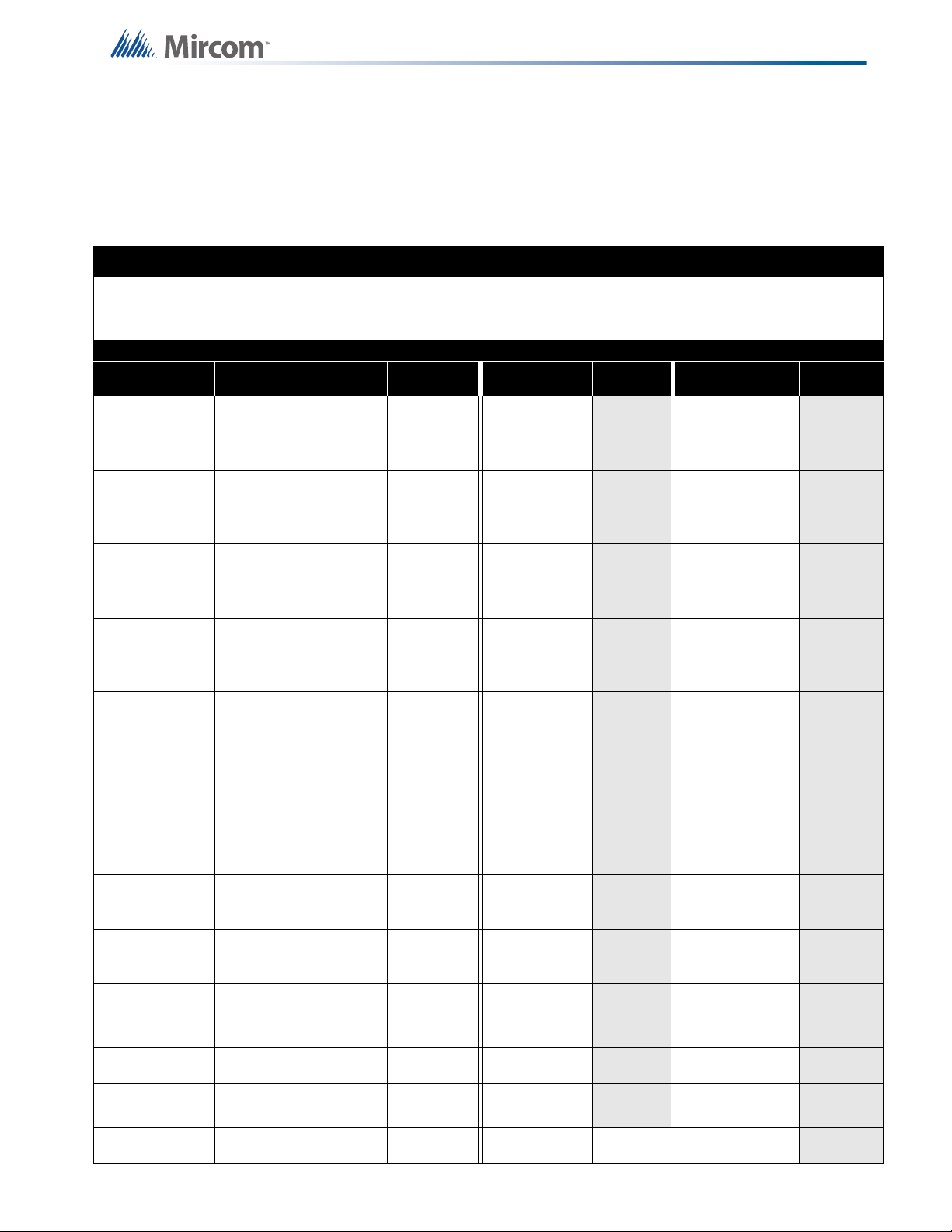
15.0 Appendix D: Power Supply and
Battery Calculations
Use the form below to determine the required secondary power supply (batteries).
IMPORTANT NOTICE
The main AC branch circuit connection for Fire Alarm Control Panel must provide a dedicated continuous power
without provision of any disconnect devices. Use #12 AWG wire with 600-volt insulation and proper over-current
circuit protection that complies with the local codes. Refer to Appendix C: Specifications for specifications.
Power Requirements (All Currents are in Amperes)
Model Number Description Qty Standby
Fire Alarm Control
FA- 30112DD(R)
FA- 30112DD(R)
FA- 3006DD(R)
FA- 3006DD(R)
FA- 300-6DR
FA- 300-6DR
ICAC-306
OCAC-304
OCAC-302
PR-300
RM-312
RM-306 6 Relay Adder Module X 0.000
SRM-312 Smart Relay Module X 0.030
RAM-300LCD
Panel, 12 Inp, 4Out
with UDACT
Using 3.9 k
Fire Alarm Control
Panel, 12 Inp, 4Out
with UDACT
Using active resistors
Fire Alarm Control
Panel, 6 Inp, 2 Out
with UDACT
Using 3.9 k
Fire Alarm Control
Panel, 6 Inp, 2 Out
with UDACT
Using active resistors
Fire Alarm Control
Panel, 6 Inp,2 Out
without UDACT
Using 3.9 k
Fire Alarm Control
Panel, 6 Inp, 2 Out
with UDACT
Using active resistors
Det Class A Converter
Adder Module
Sig Class A Converter
Adder Module--4
Circuits
Sig Class A Converter
Adder Module--2
Circuits
Polarity Reversal and
City Tie Module
12 Relay Adder
Module
Smart Remote
Annunciator
Ω resistors
Ω resistors
Ω resistors
X0.174
X0.104
X0.142
X0.112
X0.142
X0.112
X0.000
X0.000
X0.000
X0.050
X0.000
X 0.016 = 0.040
To ta l
Standby
= 0.444 =
= 0.394 =
= 0.312 =
= 0.282 =
= 0.312 =
= 0.282 =
-0.000 0.000 -0.000
-0.000 0.000 -0.000
-0.000 0.000 -0.000
=
=0.160 =
=0.080 =
=0.140 =
Alarm To tal A l ar m
0.300
(City Tie in
Use)
=
=
87
Page 88

Appendix D: Power Supply and Battery Calculations
RAM-208/216 Remote Annunciator X 0.035
RTI-1
Remote Trouble
Indicator
X0.035
Two-Wire Smoke Detectors X 0.00011
Four-Wire Smoke Detectors X
Signal Load (bells, horns, strobes, and
etc.)
X
Auxiliary Power Supply for Annunciators, etc.
Tota l cu rre nt s (Ad d ab ove c urr en ts )
STANDBY
= 0.090/0.140 =
=0.035 =
= * 0.090 = 0.090
= =
=
=
=
(A)ALARM (B)
* Assume three Initiating Circuits are in alarm.
' Use 0.084 for five minutes of alarm as a multiplier figure.
Using the Mircom MPD-65P 2-wire photoelectric smoke detector. See Appendix A for other compatible
smoke detectors.
Total Current Requirement:ALARM (B)______ Amps. (Value obtained from column B)
Battery Capacity Requirement:
([STANDBY (A) ______ ] X [(24 or 60 Hours) ___ ]) + ([ALARM (B) ______ ] X [Alarm in Hr.] _____) = (C)
______AH
Total Alarm Current: Must be 6 amperes or less for FA-300 Series. Indicating Circuits must not to exceed 5
amperes.
Battery Selection: Multiply (C) by 1.20 to derate battery.
88
Page 89

16.0 Warranty and Warning Information
WARNING!
Please read this document CAREFULLY, as it contains important warnings, life-safety, and
practical information about all products manufactured by the Mircom Group of Companies,
including Mircom and Secutron branded products, which shall include without limitation all fire
alarm, nurse call, building automation and access control and card access products
(hereinafter individually or collectively, as applicable, referred to as “Mircom System”).
NOTE TO ALL READERS:
1. Nature of Warnings. The within warnings are communicated to the reader out of an
abundance of caution and create no legal obligation for Mircom Group of Companies,
whatsoever. Without limiting the generality of the foregoing, this document shall NOT be
construed as in any way altering the rights and obligations of the parties, governed by the legal
documents that apply in any given circumstance.
2. Application. The warnings contained in this document apply to all Mircom System and shall
be read in conjunction with:
a. the product manual for the specific Mircom System that applies in given circumstances;
b. legal documents that apply to the purchase and sale of a Mircom System, which may
include the company’s standard terms and conditions and warranty statements;
c. other information about the Mircom System or the parties’ rights and obligations as may
be application to a given circumstance.
3. Security and Insurance. Regardless of its capabilities, no Mircom System is a substitute for
property or life insurance. Nor is the system a substitute for property owners, renters, or other
occupants to act prudently to prevent or minimize the harmful effects of an emergency
situation. Building automation systems produced by the Mircom Group of Companies are not
to be used as a fire, alarm, or life-safety system.
NOTE TO INSTALLERS:
All Mircom Systems have been carefully designed to be as effective as possible. However,
there are circumstances where they may not provide protection. Some reasons for system
failure include the following. As the only individual in contact with system users, please bring
each item in this warning to the attention of the users of this Mircom System. Failure to
properly inform system end-users of the circumstances in which the system might fail may
result in over-reliance upon the system. As a result, it is imperative that you properly inform
each customer for whom you install the system of the possible forms of failure:
4. Inadequate Installation. All Mircom Systems must be installed in accordance with all the
applicable codes and standards in order to provide adequate protection. National standards
require an inspection and approval to be conducted by the local authority having jurisdiction
following the initial installation of the system and following any changes to the system. Such
inspections ensure installation has been carried out properly.
5. Inadequate Testing. Most problems that would prevent an alarm a Mircom System from
operating as intended can be discovered by regular testing and maintenance. The complete
system should be tested by the local authority having jurisdiction immediately after a fire,
storm, earthquake, accident, or any kind of construction activity inside or outside the premises.
89
Page 90

Warranty and Warning Information
The testing should include all sensing devices, keypads, consoles, alarm indicating devices
and any other operational devices that are part of the system.
NOTE TO USERS:
All Mircom Systems have been carefully designed to be as effective as possible. However,
there are circumstances where they may not provide protection. Some reasons for system
failure include the following. The end user can minimize the occurrence of any of the following
by proper training, testing and maintenance of the Mircom Systems:
6. Inadequate Testing and Maintenance. It is imperative that the systems be periodically
tested and subjected to preventative maintenance. Best practices and local authority having
jurisdiction determine the frequency and type of testing that is required at a minimum. Mircom
System may not function properly, and the occurrence of other system failures identified below
may not be minimized, if the periodic testing and maintenance of Mircom Systems is not
completed with diligence and as required.
7. Improper Operation. It is important that all system users be trained in the correct operation
of the alarm system and that they know how to respond when the system indicates an alarm.
A Mircom System may not function as intended during an emergency situation where the user
is unable to operate a panic or emergency switch by reason of permanent or temporary
physical disability, inability to reach the device in time, unfamiliarity with the correct operation,
or related circumstances.
8. Insufficient Time. There may be circumstances when a Mircom System will operate as
intended, yet the occupants will not be protected from the emergency due to their inability to
respond to the warnings in a timely manner. If the system is monitored, the response may not
occur in time enough to protect the occupants or their belongings.
9. Carelessness or Safety Hazards. Moreover, smoke detectors may not provide timely
warning of fires caused by carelessness or safety hazards such as smoking in bed, violent
explosions, escaping gas, improper storage of flammable materials, overloaded electrical
circuits or children playing with matches or arson.
10. Power Failure. Some Mircom System components require adequate electrical power supply
to operate. Examples include: smoke detectors, beacons, HVAC, and lighting controllers. If a
device operates only by AC power, any interruption, however brief, will render that device
inoperative while it does not have power. Power interruptions of any length are often
accompanied by voltage fluctuations which may damage Mircom Systems or other electronic
equipment. After a power interruption has occurred, immediately conduct a complete system
test to ensure that the system operates as intended.
11. Battery Failure. If the Mircom System or any device connected to the system operates from
batteries it is possible for the batteries to fail. Even if the batteries have not failed, they must be
fully charged, in good condition, and installed correctly. Some Mircom Systems use
replaceable batteries, which have a limited life-span. The expected battery life is variable and
in part dependent on the device environment, usage and type. Ambient conditions such as
high humidity, high or low temperatures, or large temperature fluctuations may reduce the
expected battery life. Moreover, some Mircom Systems do not have a battery monitor that
would alert the user in the event that the battery is nearing its end of life. Regular testing and
replacements are vital for ensuring that the batteries function as expected, whether or not a
device has a low-battery monitor.
90
12. Physical Obstructions. Motion sensors that are part of a Mircom System must be kept clear
of any obstacles which impede the sensors’ ability to detect movement. Signals being
communicated by a Mircom System may not reach the receiver if an item (such as metal,
water, or concrete) is placed on or near the radio path. Deliberate jamming or other
inadvertent radio signal interference can also negatively affect system operation.
Page 91

Warranty and Warning Information
13. Wireless Devices Placement Proximity. Moreover all wireless devices must be a minimum
and maximum distance away from large metal objects, such as refrigerators. You are required
to consult the specific Mircom System manual and application guide for any maximum
distances required between devices and suggested placement of wireless devices for optimal
functioning.
14. Failure to Trigger Sensors. Moreover, Mircom Systems may fail to operate as intended if
motion, heat, or smoke sensors are not triggered.
a. Sensors in a fire system may fail to be triggered when the fire is in a chimney, walls, roof,
or on the other side of closed doors. Smoke and heat detectors may not detect smoke
or heat from fires on another level of the residence or building. In this situation the
control panel may not alert occupants of a fire.
b. Sensors in a nurse call system may fail to be triggered when movement is occurring
outside of the motion sensors’ range. For example, if movement is occurring on the other
side of closed doors or on another level of the residence or building the motion detector
may not be triggered. In this situation the central controller may not register an alarm
signal.
15. Interference with Audible Notification Appliances. Audible notification appliances may be
interfered with by other noise sources such as stereos, radios, televisions, air conditioners,
appliances, or passing traffic. Audible notification appliances, however loud, may not be heard
by a hearing-impaired person.
16. Other Impairments. Alarm notification appliances such as sirens, bells, horns, or strobes
may not warn or waken a sleeping occupant if there is an intervening wall or door. It is less
likely that the occupants will be alerted or awakened when notification appliances are located
on a different level of the residence or premise.
17. Software Malfunction. Most Mircom Systems contain software. No warranties are provided
as to the software components of any products or stand-alone software products within a
Mircom System. For a full statement of the warranties and exclusions and limitations of
liability please refer to the company’s standard Terms and Conditions and Warranties.
18. Telephone Lines Malfunction. Telephone service can cause system failure where telephone
lines are relied upon by a Mircom System. Alarms and information coming from a Mircom
System may not be transmitted if a phone line is out of service or busy for a certain period of
time. Alarms and information may not be transmitted where telephone lines have been
compromised by criminal tampering, local construction, storms or earthquakes.
19. Component Failure. Although every effort has been made to make this Mircom System as
reliable as possible, the system may fail to function as intended due to the failure of a
component.
20. Integrated Products. Mircom System might not function as intended if it is connected to a
non-Mircom product or to a Mircom product that is deemed non-compatible with a particular
Mircom System. A list of compatible products can be requested and obtained.
Warranty
Purchase of all Mircom products is governed by:
https://www.mircom.com/product-warranty
https://www.mircom.com/purchase-terms-and-conditions
https://www.mircom.com/software-license-terms-and-conditions
91
Page 92

92
© Mircom 2017
Printed in Canada
Subject to change without prior notice
www.mircomgroup.com
U.S.A
4575 Witmer Industrial Estates
Niagara Falls, NY 14305
Tel: (888) 660-4655
(905) 660-4655
Fax: (905) 660-4113
CANADA - Main Office
25 Interchange Way
Vaughan, ON L4K 5W3
Tel: (888) 660-4655
(905) 660-4655
Fax: (905) 660-4113
 Loading...