

Page 1
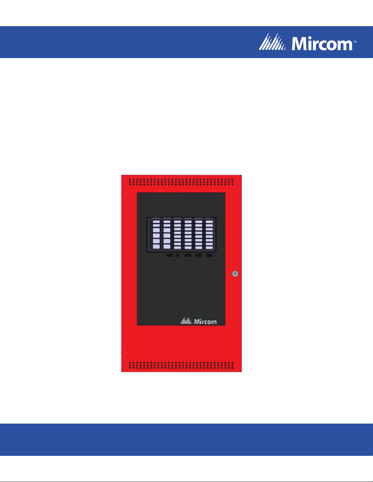
FA-1000 SERIES
Microprocessor-Based Fire Alarm Control Panel
Installation and Operation Manual
For the latest compatability information visit www.mircom.com/deviceguide
LT-600 Rev. 18
March 2016
Page 2

Page 3

Table of Contents
Table of Contents
1.0 Introduction 9
1.1 About this Manual .......................................................................................................... 9
1.2 About the FA-1000 ......................................................................................................... 9
1.2.1 Overall Features: ........................................................................................................... 9
1.2.2 Controls and Indicators .................................................................................................. 9
1.3 Contact Us ............................................. ... ... .... ...................................... .... ... ... ... ... ........ 10
1.3.1 General Inquiries ............................................................................................................ 10
1.3.2 Customer Service ........... .... ... ... ... .......................................... ... .... ................................. 10
1.3.3 Technical Support .. ... ... ... .... ... ... ... ... .... ... ... ... .... .......................................... ... ... .............. 10
1.3.4 Website ............................... ................................................................... ........................ 10
2.0 System Components 11
2.1 Chassis .......................................................................................................................... 11
2.2 Circuit Adder Modules ............................... ... .... ... ... ... .... ... ... ... ... .... ................................. 12
2.3 Auxiliary Models ............................................................................................................. 12
2.4 Enclosures ..................................................................................................................... 12
2.5 Flush Trim Rings ............................................................................................................ 13
2.6 Batteries .............................. ...................................... ....................................... .............. 13
2.7 Remote Annunciators .................................................................................................... 14
2.8 FA-1000 Fire Alarm Control Panel Kits .......................................................................... 14
2.9 FA-1000 Accessories ................................... .... ... ... ... .... ... ... .......................................... . 14
2.10 Maximum Number of Circuit Adder Modules that may be Installed ............................... 14
3.0 Mechanical Installation and Dimensions 16
3.1 BB-1024 Installation ....................................................................................................... 16
3.2 BB-1072 Installation ....................................................................................................... 17
3.3 BBX-1024DS and BBX-1024DSR Mechanical Installation ............................................ 18
3.4 Main Chassis Installation .......................................... .... ... ... ... ... .... ... .............................. 19
3.5 Main and Expander Chassis Installation ........................................................................ 20
4.0 Module Mounting Locations 21
4.1 BB-1024 and BB-1072 Main Chassis Mounting Locations ............................................ 22
4.2 BB-1072 Expansion Chassis Mounting Locations ......................................................... 23
4.3 Circuit Adder Mounting Details ...................................................................................... 24
5.0 Module Settings 25
5.1 Main Fire Alarm Module ................................................................................................. 25
3
Page 4

Table of Contents
5.1.1 Jumpers ......................................................................................................................... 25
5.2 MCC-1024-6, MCC-1024-12 Main Display Module ........................................................ 26
5.2.1 Connectors ......................... .......................................... ....................................... ........... 27
5.3 Adder Display Module .. ... ... ............................................................................................ 28
5.3.1 Connectors ......................... .......................................... ....................................... ........... 28
5.4 DM-1008A Detection Adder Module .............................................................................. 29
5.4.1 Jumpers ......................................................................................................................... 29
5.5 SGM-1004A Signal Adder Module .. ... ... .... ... ... ... .... ... ... ... .... ... ... ... ... .... ... ... ... .... ... ... ... ..... 30
5.5.1 Jumpers ......................................................................................................................... 30
5.5.2 Components ................................. .......................................... ........................................ 30
5.5.3 Operation ....................................................................................................................... 31
5.5.4 Jumpers for the Bell Cut Mode ....................................................................................... 31
5.6 RM-1008A Relay Adder Module .................................................................................... 32
5.7 UDACT-300A Digital Communicator Module ................................................................. 33
5.7.1 Jumper and connector ................................................................................................... 35
6.0 Field Wiring 36
6.1 Main Fire Alarm Module Terminal Connections ............................................................. 36
6.2 Detection Module (DM-1008A) Terminal Connections .............................. ... .... ... ... ...... .. 39
6.3 Signal Module (SGM-1004A) Terminal Connections .......................... ... ... ... .... ... ... ... ..... 40
6.4 Relay Module (RM-1008A) Terminal Connections ......................................................... 41
6.5 UDACT-300A Main Board Terminal Connections ........................ .................................. 42
6.6 PR-300 Polarity Reversal and City Tie Module Terminal Connections .......................... 43
6.7 Power Supply Connections ............................................................................................ 44
6.8 Connecting to a DCS SurGuard Receiver ...................................................................... 45
6.9 Wiring Tables and Information ....................................................................................... 46
7.0 System Checkout 47
7.1 Before Turning the Power On ........................................................................................ 47
7.2 Power-Up Procedure .................... ... ... ... .... ... ... ... .... ........................................................ 47
7.3 Troubleshooting ............................................................................................................. 47
8.0 Indicators, Controls, and Operation 49
8.0.1 Paper labels for buttons and indicators .......................................................................... 49
8.1 Common Indicators ...................................................................... ... .... ... ... ..................... 50
8.1.1 Buzzer ............................. ....................................................................... ........................ 50
8.1.2 AC ON LED ............................................................... ... ... .... ... ........................................ 50
8.1.3 Common Alarm LED .................................................................................... .... ... ........... 50
8.1.4 Common Supervisory LED ................. ... .... ..................................................................... 50
8.1.5 Common Trouble LED .... ... ... .... ... ... ... ... .... ... ... ............................................................... 50
8.1.6 Remote Failure LED ....................................................................................................... 50
8.1.7 Fire Drill LED .................................................................................................................. 50
4
Page 5

Table of Contents
8.1.8 Automatic Alarm Signal Cancel LED (Acknowledge) ....... ................ ................ .............. 50
8.1.9 General Alarm LED ........................................................................................................ 51
8.1.10 Configuration / Test Mode LED ...................................................................................... 51
8.1.11 Auxiliary Disconnect LED ............................................................................................... 51
8.1.12 Signal Silence LED ................................................ ... .... ... ... ... ... .... ... ... ... .... ... ... ... ... .... .... 51
8.1.13 Battery/Charger Trouble LED ........................................................................................ 51
8.1.14 Ground Fault LED .......................................................................................................... 51
8.1.15 CPU Fault LED .............................................................................................................. 51
8.2 Common Controls .......................................................................................................... 52
8.2.1 System Reset Button (White) ......................................................................................... 52
8.2.2 Signal Silence Button (Blue) .......................................................................................... 52
8.2.3 Fire Drill Button (Orange) ................................. ... ... ... .... ... ... ... ... .... ... ... ... .... ... ... ... ........... 52
8.2.4 Automatic Alarm Signal Cancel Button (Yellow) ........... ................................................. 52
8.2.5 General Alarm Button (Red) .......................................................................................... 52
8.2.6 Auxiliary Disconnect Button (Orange) ............................................................................ 52
8.2.7 Lamp Test Button (Orange) ................................................ ... ... .... ... ... ... .... ... ... ... ... ........ 52
8.2.8 Alm/Sup/Tbl/Bldg Audible Sil Button (Blue) ................................................................... 53
8.3 Circuit Status Indicators .. .... ... ... ... ... .... ... ... ... .... ... .......................................... ... ... ........... 53
8.3.1 Alarm Circuit Indicators .......................... ........................................................................ 53
8.3.2 Supervisory Circuit Indicators ........................................................................................ 53
8.3.3 Property and Building Safety Circuit Indicators ...................... ............. ............. ............. . 53
8.3.4 Trouble-Only Circuit Indicators ...................................................................................... 54
8.3.5 Signal Circuit Indicators ...................................... ... ... .... ... ... ........................................... 54
8.3.6 Relay Circuit Indicators .................................................................................................. 54
8.4 Circuit (Zone) Disconnect Switches ........................................................................... ... . 54
8.5 Single Stage Operation .......................................... ... .... ... ... ... ... .... ................................. 54
8.6 Two Stage Operation ..................................................................................................... 55
8.7 Circuit Types ....................................................................... ... ... .... ... .............................. 56
8.7.1 Initiating (Detection) Circuit Types ................................................................................. 57
8.7.2 Indicating (Signal) Circuit Types .................................................................................... 58
8.7.3 Evacuation Codes .......................................................................................................... 58
9.0 System Configuration 60
9.1 Introduction to Configuration .......................................................................................... 60
9.1.1 Three buttons and LED indicators are used in configuration mode ............................... 61
9.2 Configuration DIP Switch Functions .............................................................................. 62
9.3 Entering Configuration Mode ......................................................................................... 63
9.4 Exiting Configuration Mode ................................. .......................................... ... ... ... .... ... . 64
9.5 Factory Default Configuration ........................................................................................ 64
9.6 Restore to Default/Resize (Class A or B) ....................................................................... 64
9.6.1 Class B (Style B) Restore Defaults ............................................................................ ... . 65
9.6.2 Class A (Style D) Restore Defaults ............................... ... ... ... ... .... ... ... ... .... ... ... ... ........... 65
9.7 Resize System (Set Circuit Adder Module Number and Type) ........ ... ... ........................ 65
9.8 Configuration Features .................................................................................................. 66
5
Page 6

Table of Contents
9.9 Configuring Initiating and Indicating Circuits .................................................................. 68
9.10 Configuring Circuit Correlations ..................................................................................... 69
9.10.1 Correlation by Input Circuit ................. ... .... ... ... ... .... ... .......................................... ... ... ..... 70
9.10.2 Correlation by Output Circuit .......................................................................................... 70
9.11 Display Configuration ..................................................................................................... 71
10.0 Walk Test Operation 72
11.0 Appendix A: Compatible Receivers 73
12.0 Appendix B: RA-1000 Remote Annunciator Panels 74
12.1 RA-1000 Series .............................................................................................................. 74
12.1.1 Models ................................ .......... ...... .......... .......... ......... .......... .......... ......... .................. 74
12.1.2 Enclosures ..................................................................................................................... 74
13.0 Appendix C: Specifications 75
13.1 MCC-1024-6[SA] and MCC-1024-6ADS Specifications .. .... ... ... ... ... .... ... ... ... .... ... ... ... ..... 75
13.2 MCC-1024-12SA and MCC-1024-12ADS Specifications ............................................... 77
13.3 FA-1000 Expander Chassis and System Modules ......................................................... 78
14.0 Appendix D: Power Supply and Battery Calculations 80
15.0 Warranty & Warning Information 81
6
Page 7

List of Figures
List of Figures
Figure 1 BB-1024 Flush or Surface Enclosure Installation and Dimensions ............... ... ... ... .... ... . 16
Figure 2 BB-1072 Flush or Surface Enclosure Installation and Dimensions ............... ... ... ... .... ... . 17
Figure 3 BBX-1024DS and BBX-1024DSR Installation Instructions and Dimensions ................. 18
Figure 4 Main Chassis Installation .................................................... ... ... .... ... ... ... .... ... ... ... ... .... .... 19
Figure 5 Expander Chassis Installation ............................. ... ... .... ... ... ... ... .... ... ... ... ........................ 20
Figure 6 BB-1024 and BB-1072 Main Chassis Mounting Locations ............................................ 22
Figure 7 BB-1072 Expansion Chassis Mounting Locations ......................................................... 23
Figure 8 Circuit Adder Mounting Details .............................. ... .... ... ... .......................................... . 24
Figure 9 Main Fire Alarm Module ............ ... ... .... ... ... ... .... ... ... .......................................... ... ... .... .... 25
Figure 10 Main Display Module (MCC-1024-6, MCC-1024-12) ..................................................... 26
Figure 11 Main Display Module (MCC-1024-6S, MCC-1024-12S) ................................................ 27
Figure 12 Adder Display Module (Part of Expander Chassis) ........................................................ 28
Figure 13 Detection Adder Module (Model DM-1008A) ................................................................. 29
Figure 14 Signal Adder Module (Model SGM-1004A) .................................................................... 30
Figure 15 Relay Adder Module (Model RM-1008A) ....................................................................... 32
Figure 16 Digital Communicator Module (Model UDACT-300A) ...................... ... ... .... ... ... ... ... .... ... . 33
Figure 17 Polarity Reversal and City Tie Module (Model PR-300) ................................................ 34
Figure 18 Main Fire Alarm Module Terminal Connections ..................................... .... ... ... ... ... .... .... 37
Figure 19 Main Fire Alarm Module Terminal Connections (continued) .................................. .... ... . 38
Figure 20 Detection Module (DM-1008A) Terminal Connections .................................................. 39
Figure 21 Signal Module (SGM-1004A) Terminal Connections ..................................................... 40
Figure 22 Relay Module Terminal Connections ............................................................................. 41
Figure 23 UDACT-300A Terminal Connections ............................................................................. 42
Figure 24 Polarity Reversal and City Tie Module Terminal Connections ....................................... 43
Figure 25 Power Supply Connections ............................................................................................ 44
Figure 26 Connecting an FA-1000 FACP to a DCS Surguard System Receiver ............. .............. 45
Figure 27 Indicators and Control Location ..................................................................................... 49
Figure 28 Evacuation Codes .......................................................................................................... 59
Figure 29 Configuration Indicators and Controls ............................................................................ 61
7
Page 8

List of Tables
List of Tables
Table 1 Main Fire Alarm Module Circuit Details .......................................................................... 25
Table 2 Cable Connectors and Miscellaneous ............................................................................ 33
Table 3 UDACT-300A List of LEDs and their Functions ............................................................. 33
Table 4 Jumpers ....................... ... ... ... ....................................... ... .... ... ... ... ... .... ........................... 34
Table 5 Settings permitted in CAN/ULCS527 ............................................................................. 36
Table 6 Wiring Table for Input Circuits ...... .................................................................................. 46
Table 7 Wiring Table for Indicating Circuits ................................................................................ 46
Table 8 Initiating (Detection) Circuit Types ................................................................................. 57
Table 9 Indicating (Signal) Circuit Types .................................................................................... 58
Table 10 Settings permitted in UL864 ................................... ... ... ... .... ... ... ..................................... 60
Table 11 Settings permitted in CAN/ULCS527 ........................................ ... ... .... ........................... 60
Table 12 Configuration DIP Switch Functions .......................... .......................................... ... ... ... .. 62
Table 13 Configuration Features ....................... ... .... ... ... ... .... ... ... ... .... ... ... ..................................... 66
Table 14 Configuring Initiating and Indicating Circuits .................................................................. 69
Table 15 MCC-1024-6[SA] and MCC-1024-6ADS Specifications ......... ... ... ... .... ... ... ... .... ... ... ... ... .. 75
Table 16 MCC-1024-12[SA] and MCC-1024-12ADS Specifications ............................................. 77
Table 17 FA-1000 Expander Chassis and System Modules ......................................................... 78
8
Page 9

1.0 Introduction
1.1 About this Manual
This installation and operation manual provides information on installing the FA-1000 Series
Fire Alarm Control Panel.
1.2 About the FA-1000
Mircom's FA-1000 Fire Alarm Control Units provide a large capacity of supervised Class A or
B (Style D or B) initiating circuits and supervised Class A or B (Style Z or Y) indicating circuits.
All circuits are supervised for opens and ground faults, and indicating circuits are supervised
for shorts. Optional modules include additional initiating and indicating circuits, relay, and
polarity reversal and city tie. Flush or sur face mountable enclosures can be used fo r retrofits
and on new installations.
1.2.1 Overall Features:
• Basic unit has eight Class B (Style B) initiating circuits that may be configured as four
Class A (Style D) circuits. These are configurable as Alarm, Verified Alarm, Waterflow
Alarm, Sprinkler Alarm, Latching or Non-Latching Supervisory, or Trouble-Only circuits.
There are two LEDs per circuit: one for trouble (amber), and one for st atus (red/amber)
• Basic unit has four power limited Class A/B (Style Z/Y) indicating circuits with individual
trouble indicators. Each circuit can be configured as Audible (Silenceable) or Visual
(Non-Silenceable). Audibles may be configured as Steady, Temporal Code, California
Code, or March Time
• Initiating and indicating circuits may be individually disconnected by a DIP switch (slide
switch on "S" Versions for the U.S.A. market only)
• Configurable Signal Silence Inhibit, Auto Signal Silence, Two-Stage Operation, One-
Man Walk Test
For Canadian installations, disable Auto Signal Silence.
• Subsequent Alarm, Supervisory, and Trouble operation
• Two outputs for four-wire resettable smoke power supply (200 mA each max., 300 mA
total max.)
• Auxiliary relay cont act s for Common Alarm and Common Supervisory (disconnect able),
and a Common Trouble relay
• RS-485 interface for RA-1000 Series Remote Multiplex Annunciators
• Optional modules for additional initiating, indicating, and relay circuits, and city tie and
polarity reversal signalling
• Easy configuration via pushbuttons and switches
• Extensive transient protection
• Surface mountable enclosures, flush trims available
Introduction
1.2.2 Controls and Indicators
Eight pushbuttons, 16 common indicators, provision for up to 24 points (expansion chassis
adds provision for up to another 48 points).
9
Page 10

1.3 Contact Us
For General Inquiries, Customer Service and Technical Su pport you can contact us Monday to
Friday 8:00 A.M. to 5:00 P.M. E.S.T.
1.3.1 General Inquiries
Introduction
Toll Free 1-888-660-4655 (North America Only)
Local 905-660-4655
Email mail@mircom.com
1.3.2 Customer Service
Toll Free 1-888-MIRCOM5 (North America Only)
Local 905-695-3535
Toll Free Fax 1-888-660-4113 (North America Only)
Local Fax 905-660-4113
Email salessupport@mircom.com
1.3.3 Technical Support
Toll Free 1-888-MIRCOM5 (North America Only)
888-647-2665
International 905-647-2665
10
Email techsupport@mircom.com
1.3.4 Website
www.mircom.com
Page 11
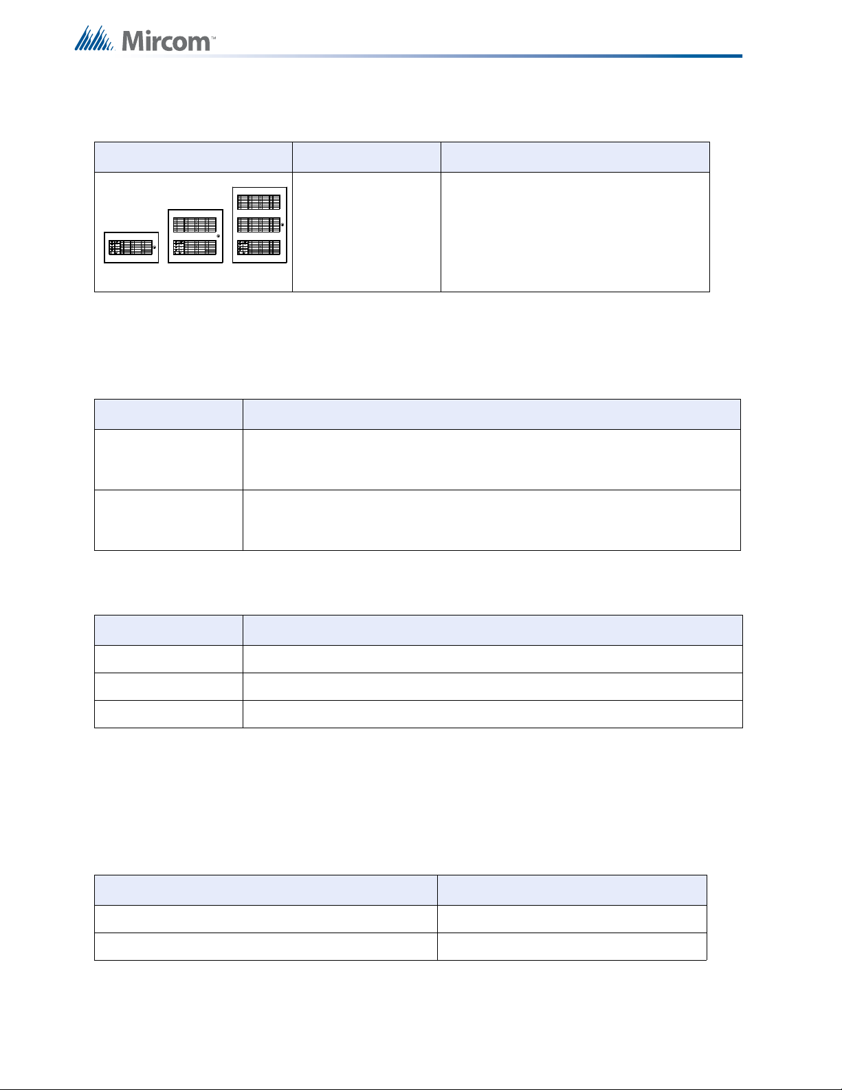
2.0 System Components
2.1 Chassis
Model Description
ECH-1048 48 zone extension chassis.
System Components
TEST/CONFIG
MODE
REMOTE
FAILURE
SYSTEM
RESET
FIRE
DRILL
AUTOMATIC
ALARM SIGNAL
CANCEL
GENERAL
ALARM1SILENCE
MCC-1024-6
(add suffix S for
slide switch
model)
COMMON
COMMON
TROUBLE
ALARM
COMMON
A.C. ON
SUPERVISORY
BATTERY
LAMP
TROUBLE
TEST
GROUND
FAULT
AUXILIARY
DISCONNECT
ALM/SUP/
TBL/BLDG
AUDIBLE SIL
SIGNAL
8141
8181
DET. ZONE
SIG. ZONE
DISCONNECT
DISCONNECT
8
ZONECONFIG.
ZONE
DISCONNECT
DISCONNECT
MCC-1024-12
Main Chassis with eight Style B / four Style D
initiating circuits, four Style Y or Z indicating
circuits, and a six ampere power su pply. For more
information see 13.0 Appendix C:
Specifications on page 75.
Same as MCC-1024-6, but with a 12 ampere
power supply. For more information see 13.0
Appendix C: Specifications on page 75.
Same as MCC-1024-6, but with disconnect slide
A.C. LINE
CIRCUIT
BREAKER
MCC-1024-6S
switches instead of DIP switches. For the U.S.A.
Market only.
Same as MCC-1024-12, but with disconnect slide
MCC-1024-12S
switches instead of DIP switches. For the U.S.A.
Market only.
Main Chassis with eight Style B / four Style D
initiating circuits, four Style Y or Z indicating
MCC-1024-6ADS
circuits, and a six ampere power su pply. For more
information see 13.0 Appendix C:
Specifications on page 75.
MCC-1024-12ADS
Same as MCC-1024-6ADS, but with a 12 ampere
power supply. For more information see 13.0
Appendix C: Specifications on page 75.
11
Page 12
2.2 Circuit Adder Modules
POLARITY
REVERSAL
ALARM
POLARITY
REVERSAL
SUPV
CITY
TIE
+ | - + | - + | -
JW4
P1 P2
BB-1024 BB-1072
Model Description
DM-1008A Eight detection circuit modules
SGM-1004A Four signal circuit modules
RM-1008A Eight relay circuit modules
2.3 Auxiliary Models
Model Description
System Components
2.4 Enclosures
PR-300 Polarity Reversal and City Tie Module
Model Description
BB-1024 (add
suffix “R” for red
enclosure)
BB-1072 (add
suffix “R” for red
enclosure)
Surface enclosure 24 circuits
Surface enclosure 72 circuits
12
Page 13
Model Description
W = 7 1/8"
H = 6 1/2"
D = 3"
BA-117
BA-110
D = 4"
H = 3 3/4"
W = 5 15/16"
BA-124
W = 6 1/2"
H = 5"
D =6 7/8"
BA-140
W = 7 5/8"
H = 6 7/8"
D = 6 3/8"
Figures Not Drawn to Scale
BBX-1024DS Universal Enclosure , white door.
BBX-1024DSR Universal Enclosure, red door.
2.5 Flush Trim Rings
Model Description
System Components
2.6 Batteries
FA-UNIV-TRB
(add suffix “R”
for red
Flush trim ring in Black
enclosure)
FA-1072TR
(add another
suffix R for red
Flush trim ring
enclosure)
Model Description
12-volt batteries (2
required for 24 volts)
10 to 40 AH
13
Page 14
2.7 Remote Annunciators
UP TO
32 ZONES
UP TO
80 ZONES
UP TO
128 ZONES
Model Description
RA-1000 Series Remote multiplex annunciator panels
2.8 FA-1000 Fire Alarm Control Panel Kits
For any other sizes, etc., components are ordered separately.
Model Description
Expandable kit for the Canadian market. Eight Class B (or four Class A)
FA-1008KA
initiating and four (Class A or B) indicating circuits, Expandable to 24 circuits,
six amp power supply (MCC-1024-6Main Chassis in a BB-1024 enclosure).
System Components
Expandable kit for the U.S.A. market. Eight Class B (or four Class A) initiating
FA-1008KUA
and four (Class A or B) indicating circuits. Expandable to 24 circuits, six amp
power supply (MCC-1024-6 main chassis in a BB-1 02 4 R enc losure).
2.9 FA-1000 Accessories
Model Description
MP-300 End-of-line Resistor Plate
MP-300R End-of-line Resistor Plate, red
MP-300S End-of-line Resistor Plate, stainless steel finish
2.10 Maximum Number of Circuit Adder Modules that may be Installed
The maximum number of circuit adder modules that may be physically installed in a system is
outlined in the table below.
Main Chassis Type Number of Adders
MCC-1024-6(S) or MCC-1024-12(S) Two circuit adder modules of any type.
MCC-1024-6(S) or MCC-1024-12(S) and ECH-1048 Eight circuit adder modules of any type.
14
Page 15
System Components
i
The "S" Version Chassis have slide switches instead of DIP switches for disconnects. The
maximum number of each circuit adder module type is outlined in the following table.
Module Description Maximum Total per
System
DM-1008A
SGM-1004A
RM-1008A
Eight detection circuit modules (total of 64
initiating circuits in a system).
Four signal circuit modules (total of 24 initiating
circuits in a system).
Eight relay circuit modules (total of 32 relay
circuits in a system).
Notes: Any FA-1000 System may have a PR-300 or UDACT-300A and up to eight (8)
Remote Multiplex Annunciators externally. As good practice, it is recommended
that circuit adder modules be installed in the order of detection modules, followed
by signal modules, followed by relay modules.
All systems can carry a maximum of eight adder modules in the combinations
permitted above.
764
316
432
15
Page 16
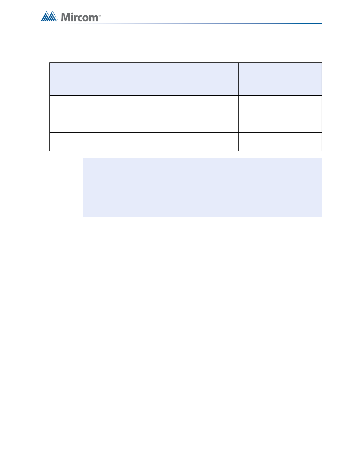
Mechanical Installation and Dimensions
(SIDE VIEW)
BACKBOX
DOOR
BACKBOX
FLUSH TRIM
WALL
SURFACE FLUSH
(SIDE VIEW)
9
4
16
DOOR
WALL
1"
MATERIAL: 18GA (0.048") THICK
COLD ROLLED STEEL
FINISH: PAINTED
“
14.5"
4
.
5
"
11"
26"
1.5"
5.4"
20.5"
3.5"
1"
3.5" is the maximum
depth for semi -flush
mounting usi ng the
flush tr im ring
1" is the minimum depth
above the wall required for
semi- flush mounting usi ng
the flush tr im ring
17"
28.5"
Adhere tr im ri ng to
wall surfac e around
FA- 1000 backbox .
PLACE FA-UN IV-TRB TRI M RING O VER BACKBOX
TRIM RING
WALL
WOOD OR
METAL S TUD
BACKBOX
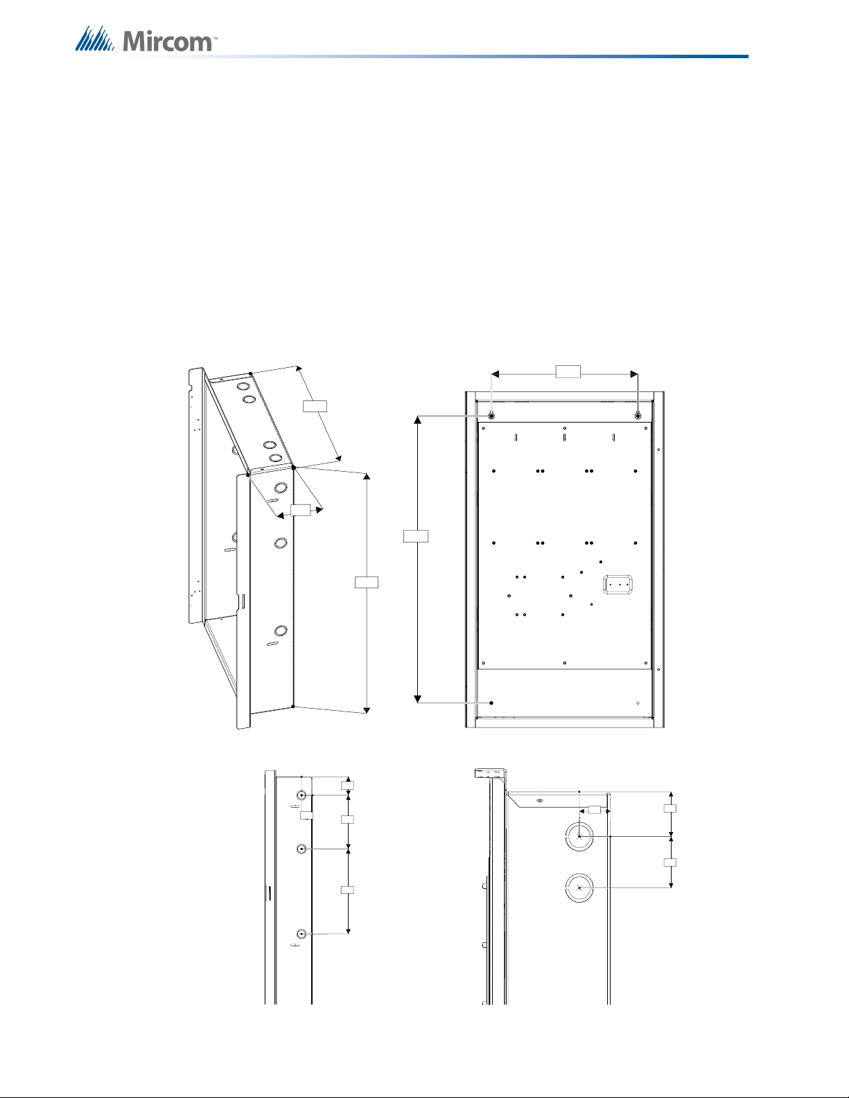
3.0 Mechanical Installation and
Dimensions
Install the enclosure as shown for the BB-1024 in Figure 1, or for the BB-1072 in Figure 2 on
page 17.
3.1 BB-1024 Installation
16
Figure 1 BB-1024 Flush or Surface Enclosure Installation and Dimensions
Page 17
3.2 BB-1072 Installation
(SIDE VIEW)
DOOR
BACKBOX
7-9/16"
BACKBOX
FLUSH TRIM
WALL
SURFACE FLUSH
(SIDE VIEW)
DOOR
FLUSH TRIM
KNOCKOUTS
WALL
BACKBOX
16"
2"
2" TYP.
7/32" DIA.
MOUNTING
HOLE
2" SINGLE
KNOCKOUT
(MODEL FA-156TR)
15"
15"
33"
2" TYP.
MATERIAL:16GA (0.059") THICK
COLD ROLLED STEEL
FINISH: PAINTED
DOOR
1-1/2"
1-1/4"
1-1/8" & 7/8"
22-1/4"
3-1/8"
8-3/4"
10-1/4"
2-1/2"
1-1/2"
7-1/2"
35-1/2"
24-3/4"
33-1/4"
22-13/16"
FLUSH TRIM
MODE: FA-1072TR
Mechanical Installation and Dimensions
Figure 2 BB-1072 Flush or Surface Enclosure Installation and Dimensions
17
Page 18
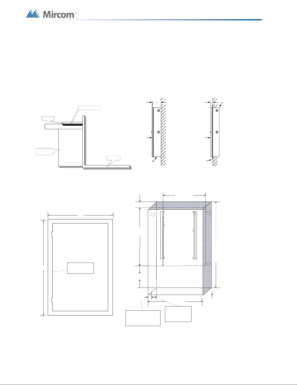
Mechanical Installation and Dimensions
26.0 "
14.5 "
4.2 "
External Dimensions
12.0 "
23.5 "
Mounting Dimensions
1.3 "
1.7 "
2.0 "
Top Vi ew
2.1 "
1.3 "
6.0 "
9.5 "
Side View
3.3 BBX-1024DS and BBX-1024DSR Mechanical Installation
The BBX-1024DS and BBX-1024DSR are suitable for flush or surface mounting, and have a
built-in trim ring.
Dimensions of Enclosure (minus built in trim ring) 14.5” x 4.2” x 26”
Distance between horizontal mounting screws 12”
Distance between vertical mounting screws 23.5”
Complete Dimensions of Enclosures 16.3” x 5.5” x 27.5”
18
Figure 3 BBX-1024DS and BBX-1024DSR Installation Instructions and Dimensions
Page 19

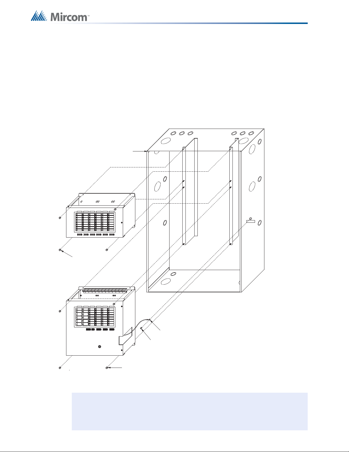
3.4 Main Chassis Installation
To install the main chassis
1. Install the main chassis in the BB-1024 backbox as shown in Figure 4 below, using the
supplied hex-nuts.
2. Group the incoming wires through the top of the enclosure to prep are them for wir ing the
modules. Do not run the wires in-between the modules since this could cause a short
circuit.
3. Use a wire tie to group wires for easy identification and neatness.
4. Be sure to connect a solid earth ground (from building system ground / to a cold water
pipe) to the chassis earth ground mounting lug, and to connect the earth ground wire
lugs from the main chassis to the ground screw on the backbox.
Mechanical Installation and Dimensions
Figure 4 Main Chassis Installation
19
Page 20
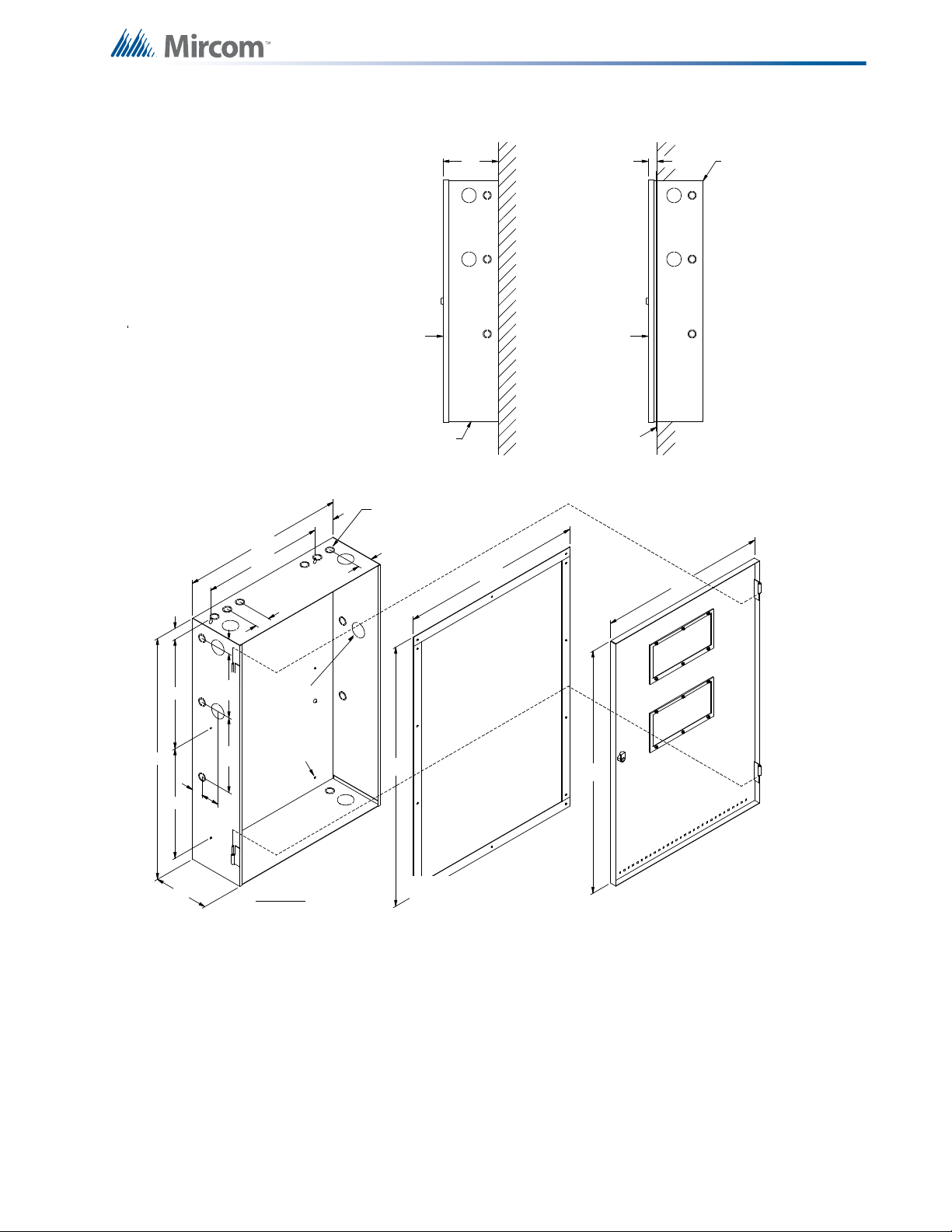
3.5 Main and Expander Chassis Installation
i
To install the expander chassis
1. Install the main and expander chassis into the BB-1072 enclosure, as shown in Fig ure 5,
using the supplied hex-nuts.
2. Group the incoming wires through the top of the enclosure to prep are them for wirin g the
modules. Do not run the wires in-between the modules since this could cause a short
circuit.
3. Use a wire tie to group wires for easy identification and neatness.
BACKBOX
Mechanical Installation and Dimensions
EXPANDER CHASSIS
#8-32 HEXNUTS (4X)
MAIN CHASSIS
1 814181818
EARTH GROUND LUG
#8 x 1/4" TYPE `B' SCREW
#8-32 HEXNUTS (4X)
Figure 5 Expander Chassis Installation
Note: Be sure to connect a solid earth ground (from building system ground / to a cold
water pipe) to the chassis earth ground mounting lug, and to connect the earth
ground wire lugs from both the main chassis and the expander chassis to the
ground screw on the backbox.
20
Page 21

Module Mounting Locations
!
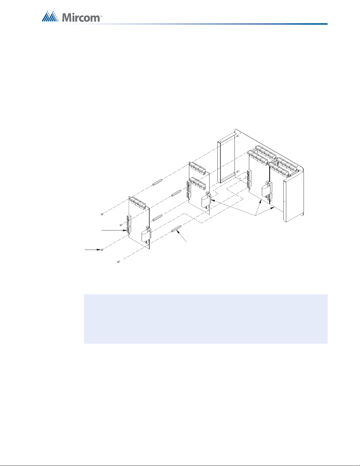
4.0 Module Mounting Locations
The main chassis in a BB-1024 or BB-1072 enclosure comes pre-assembled with all power
supply, main panel, and display components and boards. The expander chassis is equipped
with a pre-assembled display board. The PR-300 City Tie Module or the UDACT-300A Digital
Communicator may be added on the left side, as shown in Figure 8 on page 24. These
modules connect directly to the dedicated P2 connection in the upper-left corner of the main
fire alarm module.
Attention: There needs to be enough display points for each circuit on an adder
module. These display points are assigned during configuration
(See System Configuration on page 60.) in the order in which the adder
modules are electrically installed (the order in which they have their
cables connected to each other). Both the number of points available
for each display type and the number of points required for each circuit
adder module type are described in 5.0 Module Settings on page 25.
As good practice, it is recommended that circuit adder modules are
installed in the order of detection modules (DM-1008A) followed by
signal modules (SGM-1004A), followed by relay modules (RM-1008A).
To enable communication from the main fire alarm module to all of the
circuit adder modules, it is necessary to remove the continuity jumper
on JW6 (near P5, the circuit adder module connector) on the main fire
alarm module. This jumper plug must be installed on the continuity
jumper on the last installed circuit adder module. To verify the location
of the continuity jumper on a particular circuit adder module see 5.0
Module Settings on page 25
Note: Only the last circuit adder module should have a jumper plug on
its continuity jumper - all others must be left without a jumper plug.
21
Page 22

Module Mounting Locations
PR-300 city tie
module (see
Notes below)
UDACT-300A
Dialer Module
(see Notes below)
#6-32 x 1
1
/2” M/F hex
spacer
Other Circuit Adder
Module
#6-32 x
1
1
/4” screw
Other Circuit
Adder
i
4.1 BB-1024 and BB-1072 Main Chassis Mounting Locations
22
Figure 6 BB-1024 and BB-1072 Main Chassis Mounting Locations
Notes: Front plate is not shown. Other circuit adder modules may be:
• DM-1008A Detection Circuit Module
• SGM-1004A Signal Circuit Module
• RM-1008A Relay Circuit Module
To Install Circuit adder modules
1. Install circuit adder modules from right to left using the supplied stand-offs (Figure 8 on
page 24).
2. Plug the first module with its 26-pin ribbon cable into P5 on the main fire alarm module
using the included MD-579 four-wire power cable (as described in 5.0 Module
Settings on page 25).
3. You can connect a second circuit adder module by plugging its 26 pin cable into the
matching socket on the module to its right, and by installing the supplied MD-579 fourwire power cable (as described in 5.0 Module Settings on page 25).
Page 23
Module Mounting Locations
#6-32 X 1 1/4”
screw
other circuit adder
module (see Notes
below)
#6-32 1
1
/2” M/F
hex spacer
other circuit adder
modules (see
Notes below)
i
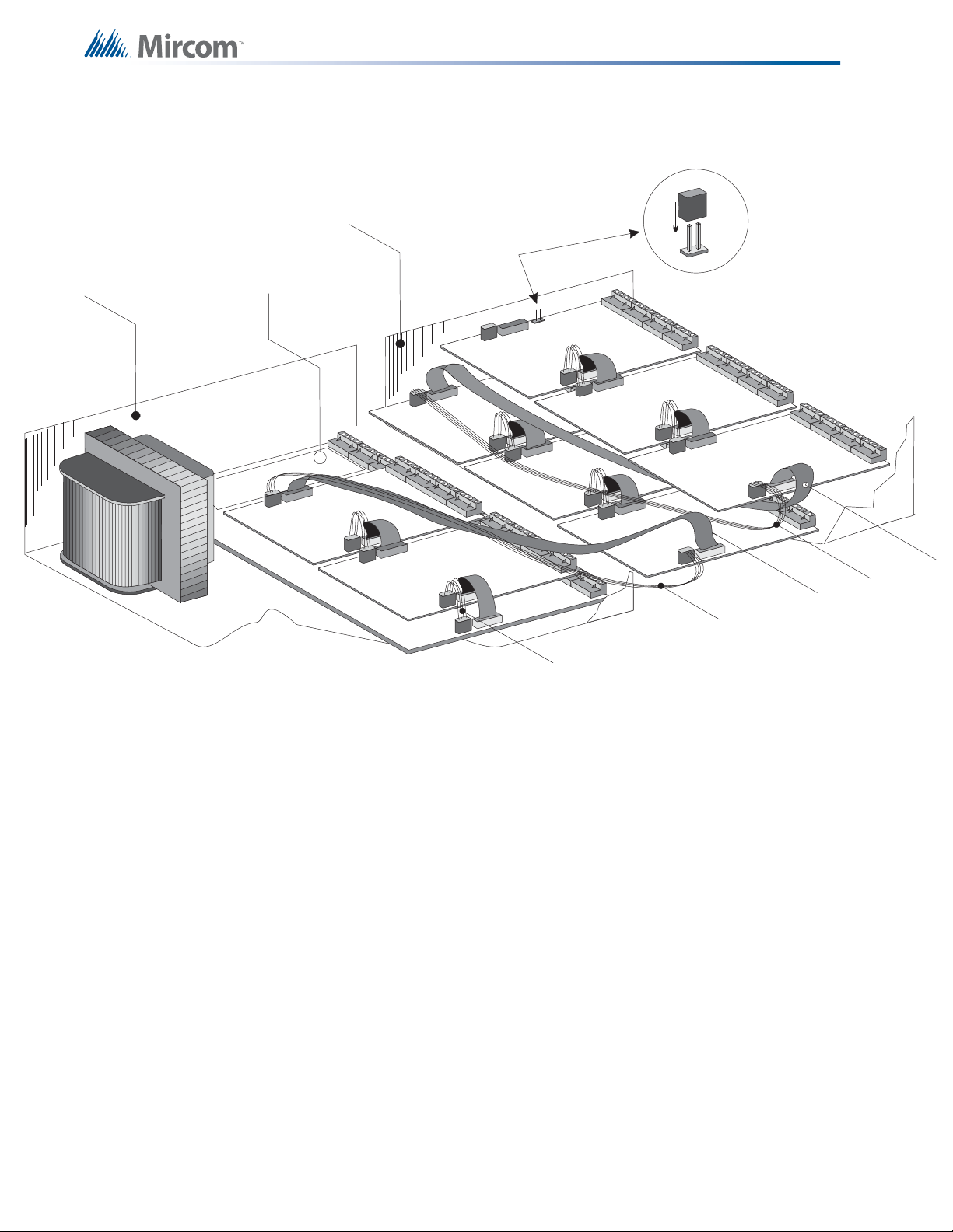
4.2 BB-1072 Expansion Chassis Mounting Locations
The BB-1072 enclosure with an ECH-1048 expander chassis is equipped with two long
extension cables: one for the 26-pin ribbon cable (MD-575) and one for the four-wire power
cable (MD-580). Circuit adder modules are installed from right to left in two tiers (back then
front). These circuit adder modules are cabled in the same way as the main chassis, except
that the first module on the back tier to the right connects (via the MD-575 and MD-580
extension cables) to the second module in the main chassis. The fourth module on the front
tier to the right connects (via MD-575 and MD-580 extension cables) to the third module on the
first tier to the left. In other words, follow a continuous right to left, bottom to top, and back to
front installation order (see Figure 7).
Figure 7 BB-1072 Expansion Chassis Mounting Locations
Notes: Front plate is not shown. Other circuit adder modules may be:
• DM-1008A Detection Circuit Module
• SGM-1004A Signal Circuit Module
• RM-1008A Relay Circuit Module
23
Page 24
Main Chassis
MD-575 Long Ribbon Cable
MD-579 Short Power Cable
MD-580 Long Power Cable
MD-580
MD-575
MCC-1024-6 or
MCC-1024-12
4.3 Circuit Adder Mounting Details
Expander Chassis
ECH-1048
Provision for
PR-300 or
UDACT-300A
Place continuity
jumper on last
board
Module Mounting Locations
8
5
2
Figure 8 Circuit Adder Mounting Details
1
MD-579
7
4
6
3
MD-575
MD-580
24
Page 25
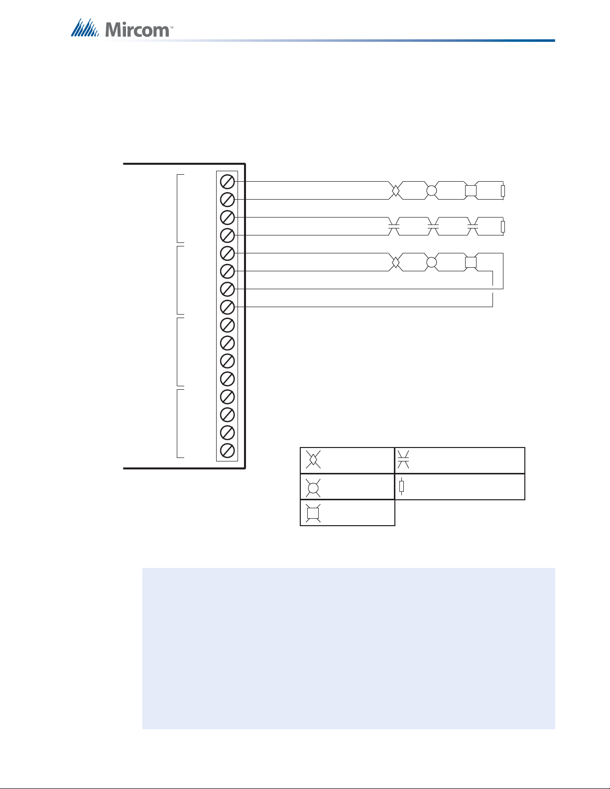
5.0 Module Settings
MAIN FIRE ALARM BOARD
FIELD WIRING TERMINALSP1
P4
P5
P6
F1
P8 P7 P10 P9
-BDG+ -B
A
T+
P3
JW1
P2
JW4
JW2 JW3
JW5
JW6
RS-485 connection
for future expansion
Connector for PR-300 Module or UDACT-300A
Connector for display module
(MCC-1024)
Connector for future
expansion
Factory connection to
Bridge Rectifier
Connection to
24VDC battery
Power connector for
adder modules
Connector for circuit adder
modules
Connector for future
expansion
Remove these jumpers
to program Class B
i
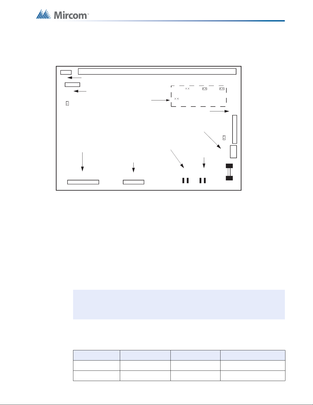
5.1 Main Fire Alarm Module
Module Settings
Figure 9 Main Fire Alarm Module
5.1.1 Jumpers
JW1 Install jumper for Class A (Style D) operation of initiating circuits 3 and 4.
JW2 Install jumper for Class A (Style D) operation of initiating circuits 5 and 6.
JW3 Install jumper for Class A (Style D) operation of initiating circuits 7 and 8.
JW4 Remove jumper if a PR-300 Module or UDACT-300A is installed.
JW5 Install jumper for Class A (Style D) operation of initiating circuits 1 and 2.
JW6 Remove continuity jumper if there are any circuit adder modules i nstalled, and
Note: The main display module (part of the main chassis) has four dedicated display
The main fire alarm module contains the following circuits, each requiring a certain number of
display points:
Table 1 Main Fire Alarm Module Circuit Details
Chassis Type Initiating Circuits In di cating circuits Display Points Required
MCC-1024-6(S) 8 Style B / 4 Style D 4 Style Y or Z 8/4 (Style B / D)
MCC-1024-12(S) 8 Style B / 4 Style D 4 Style Y or Z 8/4 (Style B / D)
install it on the last circuit adder module.
points for the four indicating circuits on the main fire alarm module.
25
Page 26
5.2 MCC-1024-6, MCC-1024-12 Main Display Module
P2
Module Settings
TEST/CONFIG
MODE
REMOTE
FAILURE
SYSTEM
RESET
FIRE
DRILL
AUTOMATIC
ALARM SIGNAL
CANCEL
GENERAL
ALARM
P1
COMMON
TROUBLE
A.C.
ON
LAMP
TEST
AUXILIARY
DISCONNECT
ALM/SUP/TBL/
BLDG AUDIBLE
SIL
SIGNAL
SILENCE
COMMON
ALARM
COMMON
SUPERVISORY
BATTERY/
CHARGER
TROUBLE
CPU FAULT
GROUND FAULT
SIGNAL 1
TROUBLE
SIGNAL 2
TROUBLE
SIGNAL 3
TROUBLE
SIGNAL 4
TROUBLE
ZONE
1
ZONE
2
ZONE
3
ZONE
4
ZONE
5
ZONE
6
ZONE
7
ZONE
8
1814 18 18 18
CONFIG .
SIG. ZONE
DISCONNECT
DET. ZONE
DISCONNECT
ZONE
DISCONNECT
ZONE
DISCONNECT
26
Figure 10 Main Display Module (MCC-1024-6, MCC-1024-12)
Page 27
5.2.1 Connectors
i
P1 Cable connects to P3 of main fire alarm module.
P2 Connection to P1 of ECH-1048 display Module if used.
SW1 to
SW5
Note: The main display module comes with a Label Sheet (NP-2854) including both
English and French slide-in labels. This sheet may be run through a laser printer
for labelling purposes before being installed. The first slide-in section comes in
two versions; one for single-stage systems, and one for two-stage systems.
The main display module provides four dedicated display points for the four indicating circuits
on the main fire alarm module. It also provides the following general-purpose display points:
Chassis Type Display Points
MCC-1024-6 24 The main display has dedicated display points for
MCC-1024-12 24
Module Settings
See 9.0 System Configuration on page 60 and 8.0 Indicators, Controls, and
Operation on page 49.
the eight initiating circuits and four indicating
circuits that are located on the main board.
On the MCC-1024-6S and MCC-1024-12S Chassis for the U.S.A. market only, the main
display module is shown in Figure 11, below. The Disconnect DIP-switches are replaced by
slide switches.
TEST/CONFIG
MODE
REMOTE
FAILURE
SYSTEM
RESET
FIRE
DRILL
AUTOMATIC
ALARM SIGNAL
CANCEL
GENERAL
ALARM
1 8
1 8
COMMON
TROUBLE
A.C.
ON
LAMP
TEST
AUXILIARY
DISCONNECT
ALM/SUP/TBL/
BLDG AUDIBLE
SIL
SIGNAL
SILENCE
COMMON
ALARM
COMMON
SUPERVISORY
BATTERY/
CHARGER
TROUBLE
CPU FAULT
GROUND FAULT
SIGNAL 1
TROUBLE
SIGNAL 2
TROUBLE
SIGNAL 3
TROUBLE
SIGNAL 4
TROUBLE
1
1
2
2
3
3
ZONE
1
ZONE
2
ZONE
3
ZONE
4
ZONE
5
ZONE
6
ZONE
7
ZONE
8
1
1
5
1
5
2
6
2
6
3
7
3
7
5
1
5
2
6
2
6
3
7
3
7
1
1
5
5
26
26
37
37
4
CONFIGURATION
CONFIGURATION
4
SIGNAL ZONE
SIGNAL ZONE
DISCONNECT
DISCONNECT
48
48
DETECTION ZONE
DETECTION ZONE
DISCONNECT
DISCONNECT
48
48
POINT/ZONE
POINT/ZONE
DISCONNECT
DISCONNECT
Figure 11 Main Display Module (MCC-1024-6S, MCC-1024-12S)
48
48
POINT/ZONE
POINT/ZONE
DISCONNECT
DISCONNECT
27
Page 28

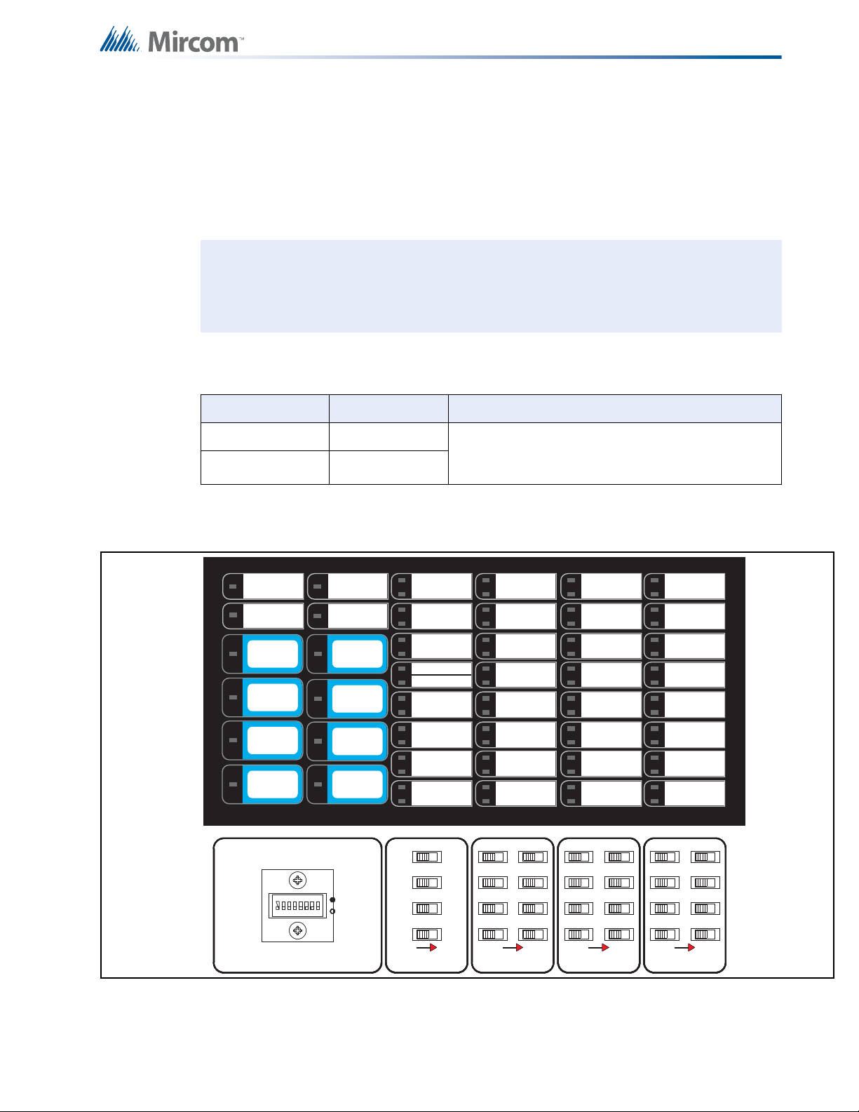
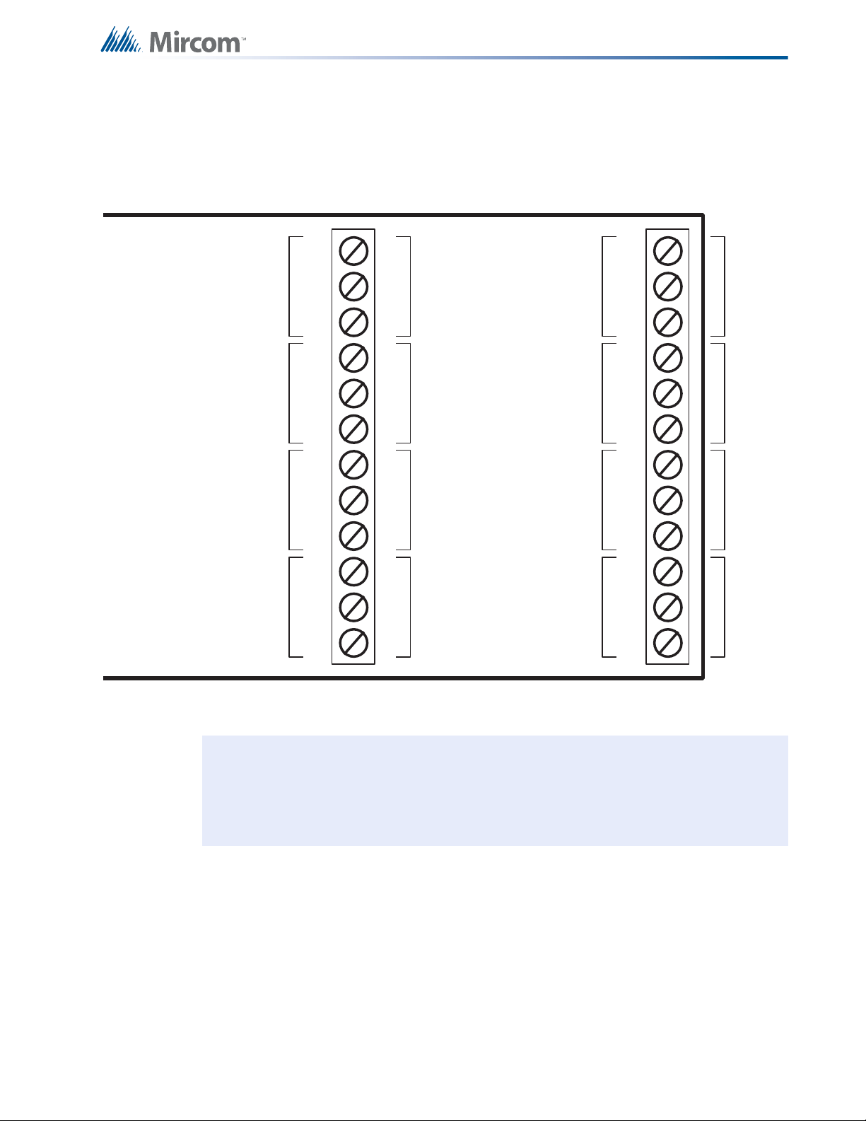
5.3 Adder Display Module
1 2 3 4 5 6 7 8
1 2 3 4 5 6 7 8
1 2 3 4 5 6 7 8
18
CIRCUIT
DISCONNECT
81
18
CIRCUIT
DISCONNECT
CIRCUIT
DISCONNECT
1 2 3 4 5 6 7 8
1 2 3 4 5 6 7 8
1 2 3 4 5 6 7 8
18
CIRCUIT
DISCONNECT
CIRCUIT
DISCONNECT
81
18
CIRCUIT
DISCONNECT
P1
P2
Zone 25
Zone 26
Zone 27
Zone 28
Zone 29
Zone 30
Zone 31
Zone 32
Zone 33
Zone 34
Zone 35
Zone 36
Zone 37
Zone 38
Zone 39
Zone 40
Zone 41
Zone 42
Zone 43
Zone 44
Zone 45
Zone 46
Zone 47
Zone 48
Zone 49
Zone 50
Zone 51
Zone 52
Zone 53
Zone 54
Zone 55
Zone 56
Zone 57
Zone 58
Zone 59
Zone 60
Zone 61
Zone 62
Zone 63
Zone 64
Zone 65
Zone 66
Zone 67
Zone 68
Zone 69
Zone 70
Zone 71
Zone 72
i
Module Settings
Figure 12 Adder Display Module (Part of Expander Chassis)
5.3.1 Connectors
P1 Cable connects to P2 of main display module.
P2 Not used.
SW1 to
SW6
The adder display module provides the following general purpose display poin ts:
Chassis Type Display Points
Note: The adder display module comes with a label sheet (NP-681) with blank slide-in
See 9.0 System Configuration on page 60 and 8.0 Indicators, Controls, and
Operation on page 49.
ECH-1048
48
labels. This sheet may be run through a laser printer for labelling purposes before
being installed.
28
Page 29

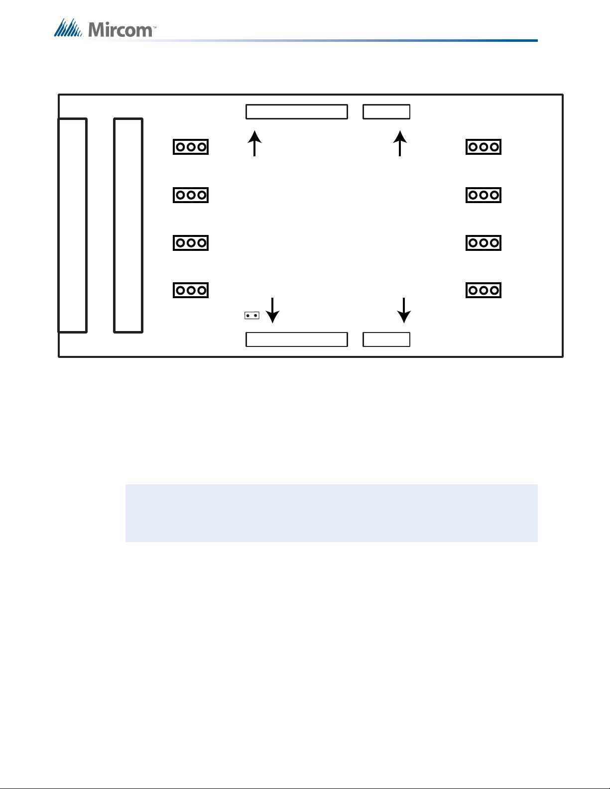
5.4 DM-1008A Detection Adder Module
P1
P3
P4
FIELD WIRING TERMINALS
P2
JW5
JW4
JW3
JW2
JW1
Data cable to P5 of main
fire alarm module or to
previous adder module.
Power connector to P6 of
main fire alarm module or
to previous adder module.
Data connector for
next adder module.
Power connector for
next adder module.
i
Module Settings
Figure 13 Detection Adder Module (Model DM-1008A)
5.4.1 Jumpers
JW1 Install jumper for Class A (Style D) operation of initiating circuits 1 and 2.
JW2 Install jumper for Class A (Style D) operation of initiating circuits 3 and 4.
JW3 Install jumper for Class A (Style D) operation of initiating circuits 5 and 6.
JW4 Install jumper for Class A (Style D) operation of initiating circuits 7 and 8.
JW5 Remove continuity jumper if there are any more adder modules installed.
Notes: Jum per JW6 on the main fire alarm module must be removed if th ere are any
adder modules installed.
The DM-1008A requires eight display points for Class B (Style B) operation, and four for
Class A (Style D) operation.
29
Page 30

5.5 SGM-1004A Signal Adder Module
P1
P3
P4
FIELD WIRING TERMINALS
P2
JW1
JW5
JW4
JW3
JW2
J11
1 2 3
GREEN SIGNAL LEDs
ZONE 4
ZONE 3
ZONE 2
ZONE 1
Data cable to P5 of main
fire alarm module or to
previous adder module
Data connector for next
adder module
Power connector to
P6 of main fire alarm
module or to previous
adder module
Power connector for
next adder module
i
i
Module Settings
Figure 14 Signal Adder Module (Model SGM-1004A)
5.5.1 Jumpers
JW1 Remove continuity jumper if there are an y mo re ad de r mod ule s installed.
JW2 Jumper pins for bell cut on Zone 1.
JW3 Jumper pins for bell cut on Zone 2.
JW4 Jumper pins for bell cut or on Zone 3.
JW5 Jumper pins for bell cut or on Zone 4.
JW11 Wire these terminals to a bell cut relay (for details see QRM-1001 Bell Cut
Module Installation and Operating Instructions, LT-666).
Notes: Jumper JW6 on the main fire alarm module must be removed if there are any
adder modules installed.
The SGM-1004A requires 4 display points.
5.5.2 Components
There are four green LEDs on the board, one for each signal zone. A green LED will illuminate
or flash following the signal rate sent to its zone. It will be off when the system is normal and it
will illuminate when a signal zone is activated. The LED does not reflect what is happening on
the signal zone, just that it is receiving data to activate that signal zone.
Note: Jumpers JW2, JW3, JW4 and JW5 are positioned on pins 2 and 3 (right two pins
30
with board orientation as shown above) from factory.
Page 31

5.5.3 Operation
!
There are three modes of o peration for this module. The basic mode o f operation does not
involve any bell cut relay or isolators connected to the signal zones. For this case, leave
jumpers JW2, JW3, JW4 and JW5 as they come on pins 2 and 3, and do not make any
connection to terminal block J11. The second mode provides bell cut operation, which allows
the silencing of the bells. The third mode is use d when isolators are to be connected to the
signal circuits. For further information on bell cut relays or isolato rs, please refer to the specific
fire alarm panel manual or the isolator instruction manual.
5.5.4 Jumpers for the Bell Cut Mode
JW2 Place jumper over pins 1 and 2 for the ability to remotely silence the bells on Zone 1.
JW3 Place jumper over pins 1 and 2 for the ability to remotely silence the bells on Zone 2.
JW4 Place jumper over pins 1 and 2 for the ability to remotely silence the bells on Zone 3.
JW5 Place jumper over pins 1 and 2 for the ability to remotely silence the bells on Zone 4.
JW11 Wire these terminals to a bell cut relay (for details see QRM-1001 Bell Cut Module
Installation and Operating Instructions, LT-666).
Module Settings
Attention: Discard jumpers on zones that are not configured for bell cut.
31
Page 32
5.6 RM-1008A Relay Adder Module
P1
P3
P4
FIELD WIRING TERMINALS
P2
JW1
Data cable to P5 of main
re alarm module or to
previous adder module
Data connector for next
adder module
Power connector to
P6 of main re alarm
module or to previous
adder module
Power connector for
next adder module
JP1
JP2
JP3
JP4
JP5
JP6
JP7
JP8
i
Module Settings
Figure 15 Relay Adder Module (Model RM-1008A)
JW1 Remove continuity jumper if there are any more adder modules installed.
• Jumper JW6 on the main fire alarm module must be removed if there are any adder
modules installed.
• The RM-1008A requires eight display points.
Note: To have all relays work independently remove all jumpers off of their pins. To tie
all commons together, have all pins in place on their respective jumpers.
32
Page 33
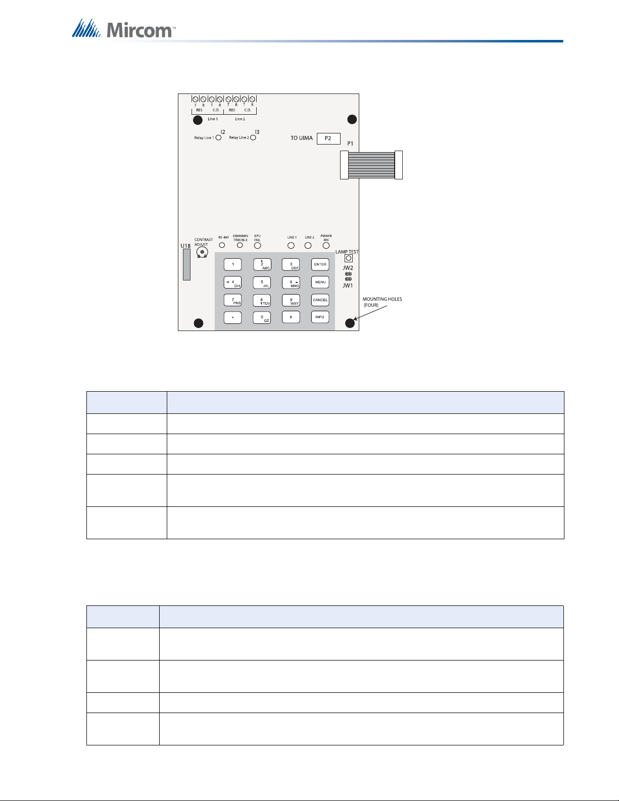
5.7 UDACT-300A Digital Communicator Module
CONNECT RIBBON
CABLE FROM P1
TO MIRCOM FIRE
ALARM CONTROL
PAN E L
VR1
Module Settings
Figure 16 Digital Communicator Module (Model UDACT-300A)
Table 2 Cable Connectors and Miscellaneous
P1
P2
U18
Lamp Test
button
UR1
Potentiometer
Ribbon Cable for connecting to Mircom Fire Alarm Control Panel (FACP).
RS-232C/RS-485 Connection for computer configuration.
Connector for CFG-300 Configuration Tool.
Press and hold this button to test all the UDACT-300A LEDs and LCD display.
This potentiometer is for adjustment of the CFG-300 LCD contrast.
The following table lists all the LEDs located on the UDACT-300A board and states the
function of each LED.
Table 3 UDACT-300A List of LEDs and their Functions
Relay Line 1 Located below Line 1 terminal block. When Line 1 relay is energized, th is green LED will
illuminate
Relay Line 2 Located below Line 2 terminal block. When Line 2 relay is energized, th is green LED will
illuminate.
RS-485 Status LED for communication, will flash when RS-485 communication is active.
Common
Steady amber for any troubles on the Fire Alarm panel or UDACT-300A.
Trouble
33
Page 34
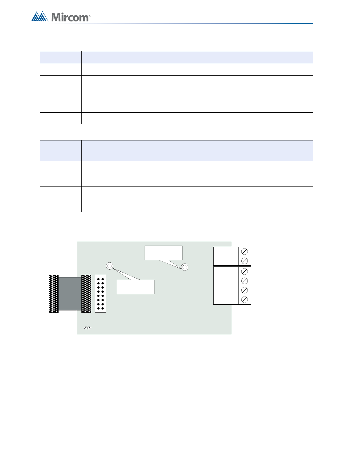
Table 3 UDACT-300A List of LEDs and their Functions (Continued)
POLARITY
REVERSAL
ALARM
POLARITY
REVERSAL
SUPV
CITY
TIE
+ | - + | - + | -
JW4
P1 P2
Mounting hole for
#6-32 screws
Mounting hole for
#6-32 screws
CPU Fail Steady amber for any on board CPU trouble.
Module Settings
Telephone
Line 1
Telephone
Line 2
Telephone status indicator LED; Red when the line is in use, Amber when there is a line
trouble.
Telephone status indicator LED; Red when the line is in use, Amber when there is a line
trouble.
Power ON Green LED is ON steady when power is supplied to the board.
Table 4 Jumpers
JUMPER
JUMPER FUNCTIONS
NUMBER
JW1 Normally open. Place jumper here and power down the UDACT-300A by disconnecting
P1 or power down the fire alarm panel (AC and Batteries), then power back to revert to
default passcode. After reset, remove the jumper. Leave normally open.
JW2 Normally open to BLOCK remote configuration via modem, PC with a UIMA converter
module or using the LCD and keypad at the UDACT-300A. Place jumper her e to ALLOW
any type of configuration. Remove jumper once configuration is complete.
Jumper JW4 on the main fire alarm panel must be removed if a UDACT-300A is installed.
Please see the UDACT-300A Installation a nd Operation Ma nual (LT-888) for more informa tion.
34
Figure 17 Polarity Reversal and City Tie Module (Model PR-300)
Page 35

5.7.1 Jumper and connector
P1 Cable to P2 of main fire alarm module.
JW4 Jumper on the main fire alarm module must be removed if a city tie module is
installed.
The alarm transmit signal to the PR-300 can be programmed to turn off when signal silence is
active. This allows the city tie box to be manually reset. On subsequent alarms the silenceable
signals will resound and the city tie box will be retriggered (see 9.0 System Configuration on
page 60).
The trouble transmit signal to the PR-300 can be programmed to delay AC power fail for zero,
1, 2, 3 hours if this is the only system trouble (see Chapter 9.0 System Configuration on
page 60).
The PR-300 does not require any display points.
Module Settings
35
Page 36

Field Wiring
6.0 Field Wiring
Table 5 Settings permitted in CAN/ULCS527
NOTICE TO USERS, INSTALLERS, AUTHORITIES HAVING JURISDICTION, AND OTHER INVOLVED PARTIES
This product incorporates field-programmable software. In order for the product to comply with the
requirements in CAN/ULCS527, Standard for Control Units for Fire Alarm Systems, certain programming
features or options must be limited to specific values or not used at all as indicated below.
Program feature or
option
System Reset and
Signal Silence on RAM208/216
6.1 Main Fire Alarm Module Terminal Connections
Wire devices to terminals as shown in Figure 18 and Figure 19. For more information see 6.9
Wiring Tables and Information on page 46, 13.0 Appendix C: Specifications on page 75, and
Permitted in CAN/
ULCS527? (Y/N)
N
Possible settings\methods
JW4 (Orange Wire) Intact =
Buzzer silence & Lamp Test
local function only. System
Reset & Signal Silence are
disabled.
Cut Jumper (Orange Wire) to
have all remote functions
operate.
Settings permitted in
CAN/ULCS527
Leave JW4 intact on
RAM-208/216
36
Page 37
LT-1007, Conventional Device Compatibility Guide.
+
-
+
-
TO
INITIATI NG
CIRCUIT
+
-
+
-
POWE R
+
-
4-W IR E
DETECTION
DEVICE
5
6
4
3
1
2
END OF LINE RELAY
LI STED S3 403
MODE L A 77-71 6B
MANUFACTURED BY
SYS TEM SENSOR
LEGEND:
P1
3. 9K 1 /2W ELR LI STED S5 434
MODEL MP-300 MANUFACTURED
BY MIRCOM
COM
NOT
USED
+
COM (- )
-
+
-
RS48 5 ( 1)
NO
NC
RS48 5 ( 2)
COM
TROUBLE
NO
NC
COM
SUPV.
NO
NC
+
-
+
-
4-W IR E-B
4-W IR E-A
ALARM
MUST BE
CONNE CTED TO A
LI STED POW ER
LIMITED SOURCE
OF S UPPLY
RESET TA BLE 4-W IRE SMOKE DE TECTO R
POWE R SUPPLI ES.
22 VDC , 20 0 m A EACH MA X., 300 mA TOTAL
MAX., 5 mV RIPPLE.
(POWER LIMITED)
COMMON TR OUBLE
CONTA CTS
28 VD C , 1 AMP
RESIS TIVE LOAD
AUXIL IARY COMMON
ALARM CONTAC TS
28 VD C , 1 AMP
RESIS TIVE LOAD
AUXIL IARY COMMON
ALARM CONTAC TS
28 VD C , 1 AMP
RESIS TIVE LOAD
USE T W IST ED SH IE LDED
PAIR
22 AW G UP TO 2000 FT.
20 AW G UP TO 4000 FT.
18 AW G UP TO 8000 FT.
RS-485 INTERFACE TO
ANNUNCIATORS AND
OTHER DEVICES
(POWER LIMITED)
!
i
Field Wiring
Figure 18 Main Fire Alarm Module Terminal Connections
Attention: Do not exceed 5 amps total current for main chassis MCC-1024-6(S)
indicating circuits, and 10 amps for main chassis MCC-1024-1 2( S).
Notes: The terminal blocks are "depluggable" for ease of wiring.
All initiating circuits are Compatibility ID "A".
All power limited circuits must use type FPL, FPLR, or FPLP power limited cable.
37
Page 38
Field Wiring
Supervisory or
Waterflow Switch (no)
Bell, horn, or strobe
Heat Detector
Legend: (See LT-1007 for compatible devices.)
Smoke Detector
3.9K 1/2W ELR listed S5434 model
MP-300 manufactured by Mircom
AUXILIARY POWER
FOR ANNUNCIATORS, ETC.
24 VDC UNFILTERED
1.7 AMPS MAXIMUM
-
+
AUX.
POWER
SUPPLY
IND2+ (Z)
IND2- (Z)
IND2- (Y/Z)
SUPERVISED INDICATING CIRCUIT #2
INDICATION
CIRCUIT 1
IND1+ (Z)
STYLE Z
WIRING
IND1- (Y/Z)
IND1+ (Y/Z)
INI1+
INI1-
INI2+
INI2-
INI3+
INI3-
INI4+
INI4-
STYLE D
INI2
STYLE D
INI1
Pull Station
IND2+ (Y/Z)
IND1- (Z)
INDICATION
CIRCUIT 2
INDICATION CIRCUITS 3 & 4
ARE NOT SHOWN
STYLE Y
WIRING
SUPERVISED INDICATING CIRCUIT #1
STYLE B
WIRING
STYLE D NOTE: INITIATING CIRCUITS IN A SERIES 1000
MUST BE ALL EITHER STYLE B OR D.
IF STYLE D IS SELECTED, THE
NUMBER OF CIRCUITS IS CUT IN HALF.
STYLE B
WIRING
STYLE D
WIRING
SUPERVISED INITIATING CIRCUIT #2
(SUPERVISORY OR WATERFLOW ZONE)
SUPERVISED INITIATING CIRCUIT #1
(ALARM ZONE)
SUPERVISED INITIATING CIRCUIT #2
(ALARM ZONE) SEE STYLE D NOTE
INITIATING CIRCUITS 5 TO 8
ARE NOT SHOWN
RTI-1 REMOTE TROUBLE INDICATOR
TRL
TRB
i
Figure 19 Main Fire Alarm Module Terminal Connections (continued)
Notes: All power limited circuits must use type FPL, FPLR, or FPLP power limited cable.
Initiating circuits are fully supervised and rated for 22 VDC, 3 mA standby, 5 mV
ripple, 50 mA max alarm. They may be configured as required. the alarm
threshold is 21 mA. Maximum loop resistance is 100 ohms; 50 ohm s pe r sid e.
Indicating circuits are fully supervised and rated for 24 VDC unfiltered 1/7 amp
max. They must be wired as shown in the wiring tables.
To supervise the 24V FWR Aux Power, use an end-of-line relay.
38
Page 39
6.2 Detection Module (DM-1008A) Terminal Connections
i
Wire devices to terminals as shown in Figure 20 below. For more information see 6.9 Wiring
Tables and Information on page 46, 13.0 Appendix C: Specifications on page 75, and LT-1007,
Conventional Device Compatibility Guide.
Field Wiring
STYLE B/D
INI1
STYLE B/D
INI2
STYLE B/D
INI3
STYLE B/D
INI4
INI1+
INI1-
INI2+
INI2-
INI3+
INI3-
INI4+
INI4-
INI5+
INI5-
INI6+
INI6-
INI7+
INI7-
INI8+
INI8-
SUPERVISED INITIATING CIRCUIT #1
(ALARM ZONE) (POWER LIMITED)
SUPERVISED INITIATING CIRCUIT #2
(SUPERVISORY OR WATERFLOW ZONE)
(POWER LIMITED)
SUPERVISED INITIATING CIRCUIT #2
(ALARM ZONE) SEE STYLE D NOTE (POWER LIMITED)
INITIATING CIRCUITS
5 TO 8 ARE NOT AVAIL.
ON FA-1012K.
LEGEND: (SEE LT-1007 FOR COMPATIBLE DEVICES)
SMOKE DETECTOR
HEAT DETECTOR
STYLE D NOTE: INITIATING CIRCUITS IN A SERIES 1000
MUST BE ALL EITHER STYLE B OR D.
IF STYLE D IS SELECTED, THE
NUMBER OF CIRCUITS IS CUT IN HALF.
SUPERVISORY OR
WATERFLOW
SWITCH (NO)
3.9K 1/2W ELR LISTED S5434
MODEL MP-300 MANUFACTURED
BY MIRCOM
STYLE B
WIRING
STYLE B
WIRING
STYLE D
WIRING
PULL STATION
Figure 20 Detection Module (DM-1008A) Terminal Connections
Notes: Initiating circuits in an FA-1000 Series Fire Alarm Pan el must all be eith er Class B
(Style B) or Class A (Style D). If Class A (Style D) is selected, the number of
circuits is cut in half.
All power limited circuits must use type FPL, FPLR, or FPLP power limited cable.
Initiating circuits are fully supervised and rated for 22 VDC, 3 mA standby, 5 mV
ripple, 50 mA max alarm. They may be configured as required. The alarm
threshold is 21 mA. Maximum loop resistance is 100 ohms, 50 ohms per side.The
terminal blocks are "depluggable" for ease of wiring.
All initiating circuits are Compatibility ID "A".
39
Page 40
6.3 Signal Module (SGM-1004A) Terminal Connections
BELL, HORN, OR STROBE
LEGEND: (SEE LT-1007 FOR COMPATIBLE DEVICES)
3.9K 1/2W ELR LISTED S5434
MODEL MP-300 MANUFACTURED
BY MIRCOM
IND2+ (Z)
IND2- (Z)
IND2- (Y/Z)
SUPERVISED INDICATING CIRCUIT #2
INDICATION
CIRCUIT 1
(POWER
LIMITED)
IND1+ (Z)
STYLE Z
WIRING
IND1- (Y/Z)
IND1+ (Y/Z)
IND2+ (Y/Z)
IND1- (Z)
INDICATION
CIRCUIT 2
(POWER
LIMITED)
STYLE Y
WIRING
SUPERVISED INDICATING CIRCUIT #1
IND4+ (Z)
IND4- (Z)
IND4- (Y/Z)
SUPERVISED INDICATING CIRCUIT #4
INDICATION
CIRCUIT 3
(POWER
LIMITED)
IND3+ (Z)
STYLE Z
WIRING
IND3- (Y/Z)
IND3+ (Y/Z)
IND4+ (Y/Z)
IND3- (Z)
INDICATION
CIRCUIT 4
(POWER
LIMITED)
STYLE Y
WIRING
SUPERVISED INDICATING CIRCUIT #3
i
Wire devices to terminals as shown in Figure 21 below. For more information see 6.9 Wiring
Tables and Information on page 46, 13.0 Appendix C: Sp ecifications on page 75, and L T-1007,
Conventional Device Compatibility Guide.
Field Wiring
Figure 21 Signal Module (SGM-1004A) Terminal Connections
Notes: All power limited circuits must use type FPL, FPLR, or FPLP power limited cable.
SGM-1004A indicating circuits are fully supervised and rated for 24 VDC
unfiltered, 1.70 amp max. They must b e wired as shown in section 6.9 Wiring
Tables and Information on page 46.
The terminal blocks are "depluggable" for ease of wiring.
40
Page 41
6.4 Relay Module (RM-1008A) Terminal Connections
RLY 1
AUX RELAY 1
CONTACTS
28 VDC, 1 AMP
RESISTIVE LOAD
AUX RELAY 2
CONTACTS
28 VDC, 1 AMP
RESISTIVE LOAD
AUX RELAY 3
CONTACTS
28 VDC, 1 AMP
RESISTIVE LOAD
AUX RELAY 4
CONTACTS
28 VDC, 1 AMP
RESISTIVE LOAD
AUX RELAY 8
CONTACTS
28 VDC, 1 AMP
RESISTIVE LOAD
AUX RELAY 7
CONTACTS
28 VDC, 1 AMP
RESISTIVE LOAD
AUX RELAY 6
CONTACTS
28 VDC, 1 AMP
RESISTIVE LOAD
AUX RELAY 5
CONTACTS
28 VDC, 1 AMP
RESISTIVE LOAD
RLY 2
RLY 3
RLY 4
COM
RLY 5
NO
NC
RLY 6
RLY 7
RLY 8
COM
NO
NC
COM
NO
NC
COM
NO
NC
COM
NO
NC
COM
NO
NC
COM
NO
NC
COM
NO
NC
i
Wire devices to terminals as shown in Figure 22 below. For more information see 6.9 Wiring
Tables and Information on page 46, 13.0 Appendix C: Specifications on page 75, and LT-1007,
Conventional Device Compatibility Guide.
Field Wiring
Figure 22 Relay Module Terminal Connections
Notes: All power limited circuits must use type FPL, FPLR, or FPLP power limited cable.
All relay circuits must be connected to a listed power limited source of supply.
The terminal blocks are "depluggable" for ease of wiring.
41
Page 42

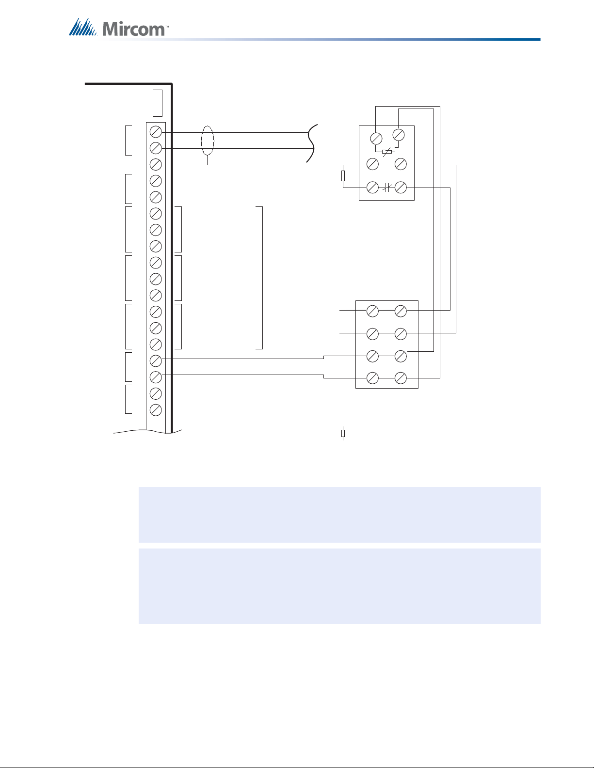
6.5 UDACT-300A Main Board Terminal Connections
TTRR
premise telephone
IF permitted
TTRR
LINE-1 LINE-2
1
23
4
8
5
76
Public switch
Telephone company
wiring
TIP
RING
TIP
RING
RJ31X
RED
GREEN
GREY
BROWN
RES RESC.O. C.O.
Line 2 is Wired as shown for Line 1
UDACT-300A
i
Wire the two telephone line devices to terminals as shown below in Figure 23 below.
The UDACT-300A terminals are located on the top left hand corner of the board. If using a
cellular or wireless service, use the Line 2 interface connection only.
Field Wiring
Figure 23 UDACT-300A Terminal Connections
Note: Most AHJ's do not allow the connection of premises telephones. See UDACT-
300A Instruction and Operation Manual (LT- 888) for further details.
42
Page 43

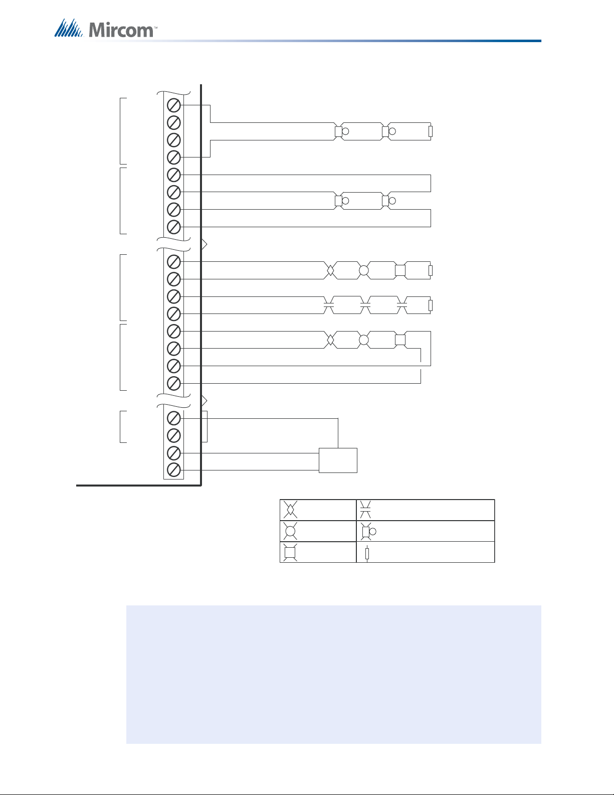
6.6 PR-300 Polarity Reversal and City Tie Module Terminal
Cable Resistance
Less than or equal to
3000 ohms
i
Connections
Wire as shown below in Figure 24 using proper wire gauges. For more information see
Appendix C: Specifications on page 75.
For use in the U.S.A., the installer must add an Atlantic Scientific (Tel. 407-725-8000) Model
#24544 Protective Device, or similar UL-Listed QVRG Secondary Protector, as shown. For
use in Canada, the protective device is still recommended, but the PR-300 may be connected
directly to polarity reversal or city tie wiring.
Field Wiring
Figure 24 Polarity Reversal and City Tie Module Terminal Connections
• Plug PR-300 ribbon cable (P1) into connector (P2) of the main fire alarm
module.
• Cut jumper (JW1) on the PR-300 module in order to transmit a trouble condition
to the monitoring station.
• Remove jumper plug from jumper JW4 on the main fire alarm module.
• The polarity reversal interface is power limited and must use type FPL, FPLR,
or FPLP power limited cable.
• For polarity reversal operation, short tie the city tie connection.
• Either the PR-300's city tie or polarity reversal interface may be used, but not
both.
• The city tie interface is not power limited.
• The terminal blocks are "depluggable" for ease of wiring.
43
Page 44

6.7 Power Supply Connections
!
The power supply is part of the main chassis. The ratings are outlined in the table below.
Field Wiring
Model Electrical Input Ratings Power Supply
Total Current
MCC-1024-6(S)
Main Chassis
MCC-1024-12(S)
Main Chassis
For more information see Appendix C: Specifications on page 75. Wire as shown in Figure 25
using proper wire gauges.
120 VAC, 60 Hz / 240 VAC, 50Hz 6 amps maximum
120 VAC, 60 Hz / 240 VAC, 50Hz 12 amps maximum
P7P8 P10
-
BLACK
BAT
P9
+
TO DEDICATED
BRANCH CIRCUIT
Battery Fuse on Main
Module
Replace with 20 amp, 1
Fast Acting Fuse
Replace with 20 amp, 1
Fast Acting Fuse
CONNECT GREEN
EARTH GROUND WIRE
TO MAIN MODULE PCB
MOUNTING SCREW.
¼"
¼"
TO 24 VDC
BATTERY
RED
N
LL
240V, 50Hz
120V, 60Hz
Figure 25 Power Supply Connections
Attention: To prevent sparking, connect batteries after the system main A.C. power
turns on.
Do not exceed power supply ratings.
G
GREEN
44
Page 45

6.8 Connecting to a DCS SurGuard Receiver
A
L
A
R
M
R
E
L
A
Y
S
P
V
R
E
L
A
Y
T
R
B
L
R
E
L
A
Y
R
i
n
g
T
i
p
Telephone
Line A
Connec tion
G
S
3
0
7
0
S
3
0
7
0
T
R
B
L
1
2
V
E
O
L
-
A
l
l
u
n
it
s
m
u
s
t
b
e
i
n
s
t
a
l
le
d
in
t
h
e
s
a
m
e
ro
o
m
.
-
A
ll
e
x
t
e
n
d
e
d
w
i
r
in
g
m
u
s
t
b
e
i
n
c
o
n
d
u
i
t
.
-
D
is
ta
n
c
e
m
a
x
1
8
meters
-
R
e
p
r
o
g
r
a
m
m
e
s
s
a
g
e
s
fr
o
m
G
S
3
0
7
0
Z
1
,
Z
2
,
a
n
d
Z
3
To GSM/GPRS
T
yp
i
c
a
l
In
s
t
a
ll
a
t
i
o
n
in
C
a
n
a
d
a
Line 2
Ring
Tip
Line 1
Ring
Tip
PCS-100
P
O
W
E
R
2
4
V
G
N
D
P
G
M
4
G
N
D
1
4
V
N
C
C
O
M
N
O
T
B
L
R
E
L
A
Y
J
W
1
1
0
P
G
M
4
AUX SUPPLY
+
-
+
-
Internet
Com puter
Printer
SUR-GARD
SYSTEM IV
Internal IP: X.X.X.X
External IP: X.X.X.X
SG-Systems
Cons ole 2.1
Default Gateway: X.X.X.X
Sub-Net Mask:X.X.X.X
Port #: YYYY (UDP)
Router
F
A
-
10
0
0
–
G
S
3
0
7
0
C
o
n
n
e
c
t
i
o
n
–
T
y
p
i
c
a
l
D
i
a
g
r
a
m
N
O
C
N
O
C
N
O
C
1
4
C
O
M
1
7
Z
3
1
6
Z
2
1
5
Z
1
T
1
R
1
Telephone
Line B
Connec tion
2
0
(
-
)
1
9
(
+
)
Trouble Zone Input
FA-1000
i
A typical connection is shown in Figure 26. For information on Compatible DACR Receivers
see 11.0 Appendix A: Compatible Receivers on page 73.
Field Wiring
Figure 26 Connecting an FA-1000 FACP to a DCS Surguard System Receiver
Note: The DSC interface is required if the installation requires S559 certification. If
S559 certification is not required, i.e. only local operation of the fire alarm panel,
this DSC interface is not required.
45
Page 46

6.9 Wiring Tables and Information
i
i
Table 6 Wiring Table for Input Circuits
Wire Gauge Maximum Wiring Run to Last Device (ELR)
(AWG) ft m
22 2990 910
20 4760 1450
18 7560 2300
16 12000 3600
14 19000 5800
12 30400 9200
Note: Maximum loop resistance should not exceed 100 Ohms.
Field Wiring
Main board SGM-1004A indicating circuits are rated for 1.7 amps each. The indicating circuits
are rated for 1.7 amps each.
Table 7 Wiring Table for Indicating Circuits
TOTAL
SIGNAL
LOAD
Amperes ftmftmftmftm Ohms
0.06 2350 716 3750 1143 6000 1829 9500 2895 30
0.12 1180 360 1850 567 3000 915 4720 1438 15
0.30 470 143 750 229 1200 366 1900 579 6
0.60 235 71 375 114 600 183 950 289 3
0.90 156 47 250 76 400 122 630 192 2
1.20 118 36 185 56 300 91 470 143 1.5
1.50 94 29 150 46 240 73 380 115 1.2
1.70 78 24 125 38 200 61 315 96 1.0
Note: Maximum voltage drop should not exceed 1.8 volts.
MAXIMUM WIRING RUN TO LAST DEVICE (ELR) MAX. LOOP
18AWG 16AWG 14AWG 12AWG
RESISTANCE
46
Auxiliary Power
Wiring
RS-485 Wiring See the wiring information for the remote annunciator being used.
4-Wire Smoke
Wiring
Use Table 7 Wiring Table for Indicating Circuits above to see the wiring
information for the remote annunciator being used.
The maximum allowable current is 0.2 amperes. The maximum allowed
voltage drop is 1 volt. Refer to Table 7 Wiring Table for Indicating
Circuits above.
Page 47

7.0 System Checkout
7.1 Before Turning the Power On
1. To prevent sparking, do not connect the batteries. Connect the batteries after powering
the system from the main AC supply.
2. Check that all modules are installed in the proper location with the pro pe r co nnections.
3. Check all field (external) wiring for opens, shorts, and ground.
4. Check that all interconnection cables are secure, and that all connectors are plugged in
properly.
5. Check all jumpers and switches for proper setting.
6. Check the AC power wiring for proper connection.
7. Check that the chassis is connected to EARTH GROUND (cold water pipe).
8. Make sure to close the front cover plate before powering the system from main AC
supply.
System Checkout
7.2 Power-Up Procedure
1. After completing the above procedures, power-up the p anel. The gree n AC ON LED and
the Common Trouble LED should illuminate, and the buzzer should sound.
2. Press the System Reset button. Since the batteries are not connected, the Battery/
Charger Trouble LED should illuminate, the trouble buzzer should sound intermittently,
and the Common Trouble LED should flash.
3. Connect the batteries while observing correct polarity: the red wire is positive (+) and the
black wire is negative (-). All indicators should extinguish except for the AC ON LED.
4. Configure the fire alarm control panel as described in9.0 System Configuration on
page 60.
7.3 Troubleshooting
Message Description
Circuit Trouble Normally when a circuit trouble occurs, its designated trouble indicator will be
illuminated, as well as the Common Trouble indicator and Trouble buzzer. To
correct the fault, check for open wiring on that particular circuit loop or see if the
circuit disconnect switch is in the ON or CLOSED position. Note: disconnecting a
circuit will cause a system trouble (off-normal position).
Remote Fail The panel will display a Remote Fail for any failure reported by or failure to
communicate with a remote annunciator or other remote device.
Ground Fault The FA-1000 panel has a Common Ground Fault Detector. To correct the fault,
check for any external wiring touching the chassis or other earth ground connection.
Battery/Charger
Trouble
Check for the presence of batteries and their conditions. Low voltage (below 20.4V)
will cause a battery trouble. If battery/charger trouble condition persists, replace the
batteries as soon as possible. If the problem still persists, main board may need to
be replaced.
47
Page 48

Message Description
System Checkout
Configuration
Mode
If the Test/Config Mode LED is illuminated steadily, the system is in either
configuration mode or walk test mode. If the LED is flashing, the configuration has
been corrupted and has been rese t to de fault s; you must therefor e review / re-enter
your configuration.
Common
Trouble
If only a common trouble is indicated on the main panel and none of the above
confirming trouble indicators are on, then check the following for possible fault:
i) Check for any missing interconnection wiring.
ii) Check for any missing modules that are part of the configuration.
iii) Check jumper positions. Particularly ensure that the continuity jumper is installed
only on the last circuit adder module in the system.
iv) Check for improperly secured cabling.
CPU Fault This LED will only illuminate for a short period upon power up when system is
normal.It will illuminate steadily when there has been a major CPU failure. This
indicates the system is not functioning and main board must be replaced.
48
Page 49
Indicators, Controls, and Operation
1814 18 18 18
CONFIG .
SIG. ZONE
DISCONNECT
DET. ZONE
DISCONNECT
ZONE
DISCONNECT
ZONE
DISCONNECT
COMMON
1
ZONE
2
ZONE
3
ZONE
4
ZONE
5
ZONE
6
ZONE
7
ZONE
8
ALARM
SUPERVISORY
COMMON
REMOTE
FAILURE
TEST/CONFIG
MODE
SYSTEM
RESET
FIRE
DRILL
GENERAL
ALARM
COMMON
TROUBLE
A.C.
ON
LAMP
TEST
AUXILIARY
DISCONNECT
SIGNAL
SILENCE
CPU FAULT
GROUND FAULT
SIGNAL 1
TROUBLE
SIGNAL 2
TROUBLE
SIGNAL 3
TROUBLE
SIGNAL 4
TROUBLE
ZONE
BATTERY/
CHARGER
TROUBLE
AUTOMATIC
ALARM SIGNAL
CANCEL
ALM/SUP/TBL
/BLDG
AUDIBLE SIL
8.0 Indicators, Controls, and Operation
Refer to Figure 27 below for LED indicators, control buttons, and switches locations.
Figure 27 Indicators and Control Location
The main display panel on the fire alarm control unit consists of:
A) • 16 common LED indicators • 8 Common Buttons
• 28 circuit / circuit indicators • Configuration DIP switch
8.0.1 Paper labels for buttons and indicators
Each display is supplied with laser printable labels. These labels slide into the plastic label
An adder display module is part of the ECH-1048 Expander Chassis, which adds 48
B)
circuit / circuit indicators and disconnect switches.
LED indicators may be amber, red, or green, and may illuminate continuously (steady),
C)
or at one of two flash fates
templates on the panel. The label paper for the main display includes English and French
versions (Mircom #NP-2854, NP-680). Two slide-in labels are also included for single-stage
and two-stage operation. For the adder display, the labels are blank (Mircom #NP-681).
• 28 circuit disconnect DIP switches
• Fast flash: 120 flashes per minute, 50% duty cycle, for su pe rv isor y ala rm s
• Trouble flash: 20 flashes per minute, 50% duty cycle
49
Page 50

8.1 Common Indicators
8.1.1 Buzzer
The buzzer is activated by any of the following:
• Fire alarm: steady
• Supervisory alarm: fast flash rate
• Trouble: trouble flash rate
If the buzzer turns on in response to a non-latching trouble or supervisory, it will turn off if the
condition causing it to sound goes away and there is no other reason for it to be on.
8.1.2 AC ON LED
The green AC ON LED illuminates steadily while the main AC power is within acceptable
levels. It turns off when the level falls below the power-fail threshold and the panel switches to
standby (battery) power.
8.1.3 Common Alarm LED
Indicators, Controls, and Operation
The red Common Alarm LED illuminates steadily whenever the panel is in alarm as a result of
an alarm on any initiating circuit or activation of the manual red General Alarm Button. Since
all alarms are latched until the panel is reset, the LED will remain on until then.
8.1.4 Common Supervisory LED
The amber Common Supervisory LED illuminates steadily when there is a supervisory alarm
in the panel resulting from any latching or non-latching supervisory circuit. The LED turns off if
all non-latching supervisory circuits are restored and there are no active latching supervisory
circuits. Latching supervisory alarms remain active until the panel is reset.
8.1.5 Common Trouble LED
The Common Trouble LED flashes amber at the trouble flash rate when the panel detects any
trouble condition. It turns off when all non-latching troubles are cleared.
8.1.6 Remote Failure LED
The Remote Failure LED flashes amber at the trouble flash rate if the panel detects:
• Trouble at the city tie, or
• Trouble at the UDACT, or
• Communication trouble with a remote annunciator, or
• Local trouble with a remote annunciator.
It turns off once these conditions return to normal.
50
8.1.7 Fire Drill LED
The amber Fire Drill LED illuminates steadily while the fire drill is active.
8.1.8 Automatic Alarm Signal Cancel LED (Acknowledge)
If the panel is configured as two stage, the Automatic Alarm Signal Cancel LED illuminates
steadily when the timer is cancelled by activating the Automatic Alarm Signal Cancel or Signal
Silence buttons. If the Auto General Alarm timer times out and puts the panel into General
Alarm, the LED turns off.
Page 51

8.1.9 General Alarm LED
i
The red General Alarm LED illuminates steadily after the General Alarm button is pressed, a
general alarm initiating circuit is activated, or the Auto General Alarm timer times out. Once
the General Alarm LED turns on, it will stay active until the panel is reset.
8.1.10 Configuration / Test Mode LED
The amber Configuration / Test Mode LED illuminates steadily to indicate that the panel is in
either walk test or configuration mode. If the panel is left in either mode for over an hour with
no operator activity, this LED will flash at the trouble flash rate.
8.1.1 1 Auxiliary Disconnect LED
The amber Auxiliary Disconnect LED flashes at the trouble flash rate after the Auxiliary
Disconnect button is pressed. It turns off after the button is pressed a second time. When on, it
indicates that common alarm and common supervisory relays are not activated, and
programmable relays (if disconnect is enabled) are not activated. The city tie module, if
installed, is also inactive.
8.1.12 Sign al Silence LED
Indicators, Controls, and Operation
The amber Signal Silence LED flashes at the trouble flash rate when indication circuits are
silenced either by the Signal Silence button or by the Auto Signal Silence timer. It turns off
when the signals are re-sounded by a subsequent alarm.
Note: For Canadian installations, disable the Auto Signal Silence timer.
8.1.13 Battery/Charger Trouble LED
The Battery/Charger Trouble LED flashes amber at the trouble flash rate when the battery is
either low (below 20.4 VDC) or disconnected.
8.1.14 Ground Fault LED
The Ground Fault LED flashes amber at the trouble flash rate when the Ground Fault Detector
detects a ground fault on any field wiring. It turns off when the ground fault is cleared.
8.1.15 CPU Fault LED
The CPU Fault LED Indicator illuminates steadily to indicate a microprocessor failure on the
main board.
51
Page 52

8.2 Common Controls
8.2.1 System Reset Button (White)
The System Reset button resets the fire alarm control panel and all circuits:
Indicators, Controls, and Operation
• Resets all latching trouble
conditions
• Resets four-wire smoke supply • Turns off all indicating circuits
• Turns off Signal Silence, Automatic
Alarm Signal Cancel & General
Alarm LEDs
• Stops and resets all timers • Processes inputs as new events
• Aux Disconnect is not affected • Reset cannot be activated until the Signal Silence
8.2.2 Signal Silence Button (Blue)
Pressing the Signal Silence button after the panel is in alarm turns on the Signal Silence LED
and deactivates any silenceable indicating circuits. Non-Silenceable circuits are unaffected.
Signals will re-sound upon any subsequent Alarm. This button does not function during any
configured Signal Silence Inhibit timer period. It also does not function if indicating circuits are
active as the result of a Fire Drill. In a two-stage system, the Signal Silence button silences the
stage 1 and stage 2 alarms.
8.2.3 Fire Drill Button (Orange)
The Fire Drill button activates all programmed and non-disconnected indicating circuits, but
does not transmit any Alarms via the city tie or common alarm relay. The Fire Drill button may
be programmed to operate specific indicating circuits. The Fire Drill is cancelled by pressing
the button again (toggle switch), or if the panel goes into a real Alarm.
• Resets all initiating circuits
• Turns off Fire Drill
Inhibit timer has expired
52
8.2.4 Automatic Alarm Signal Cancel Button (Yellow)
If the Panel is not configured for two stage operation, this button does nothing. If the panel is
configured for two stage operation, pressing the Automatic Alarm Signal Cancel button while
the Auto General Alarm timer is timing (there is an Alarm in the panel, but it is still in the first
stage) cancels the timer and turns the Automatic Alarm Signal Cancel LED on steady amber.
8.2.5 General Alarm Button (Red)
Pressing the General Alarm button immediately sends the panel into General Alarm. It will also
re-activate the signals if they have been silenced during a General Alarm initiated through a
detection circuit. The General Alarm condition remains active until the panel is reset.
8.2.6 Auxiliary Disconnect Button (Orange)
Pressing the Auxiliary Disconnect button activates the Auxiliary Disconnect function. Pressing
the button again deactivates the functi on .
8.2.7 Lamp Test Button (Orange)
Pressing the Lamp Test button causes all front panel indicators to illuminate and sounds the
buzzer steadily. If Lamp Test is active for more than ten seconds, the Common Trouble LED is
activates.
Page 53

8.2.8 Alm/Sup/Tbl/Bldg Audible Sil Button (Blue)
Activation of the Alm/Sup/Tbl/Bldg Audible Sil button while the buzzer is sounding silences the
buzzer. The buzzer will resound if there is a subsequent event. Pressing the button when the
buzzer is not sounding has no effect.
8.3 Circuit Status Indicators
There is one pair of circuit Status LEDs for each initiating, indicating, and relay circuit. The first
four indicating circuits on the main fire alar m module are part of the common indicators. All
other circuits (including the first eight initiating circuits on the main fire alarm module) are
arranged in columns of eight indicators numbered from one to eight. For each circuit, the
upper circuit Status LED may be red or amber, and will either be steadily illuminated or
flashing at either the fast flash or trouble flash rates, depending on the operation. The amber
Circuit Trouble LED flashes at the trouble flash rate when active. The Status LED is used on
initiating circuits only.
After the first eight initiating circuits (corresponding to the first column of circuit LED's) the
circuit LEDs are configured in the same order as any adder modules. If there are insufficient
display adders for the number of circuits on the panel, the last circuits will not be displayed. If
there are too many displays for the number of circuits on the panel, the unassigned ones will
be unused.
Indicators, Controls, and Operation
8.3.1 Alarm Circuit Indicators
The operation of alarm circuit indicators applies to initiating circuits configured as verified
alarm, non-verified alarm, water-flow alarm, sprinkler alarm, or general alarm circuits.
• The Circuit Trouble LED flashes at the trouble flash rate to indicate circuit trouble
(open circuit or Style D / Class A trouble) or a disconnected circuit. It always turns off
when the circuit is in alarm.
• The Circuit Status LED illuminates steady red when the circuit is in alarm. On verified
alarm circuits, sprinkler alarm, and water-flow alarm circuits, the circuit Status LED will
illuminate at the fast flash rate during the pre-alarm condition. This LED will also flash at
the fast flash rate while an active circuit is being un-disconnected.
8.3.2 Supervisory Circuit Indicators
The operation of supervisory circuit indicators applies to initiating circuits configured as
latching or non-latching supervisory circuits.
• The Circuit Trouble LED flashes at the trouble flash rate to indicate circuit trouble (open
circuit or Class A (S tyle D) trouble) or a disconnected circuit. It always turns off when the
circuit is in alarm.
• The Circuit Status LED turns on steady amber when the corresponding circuit is in
alarm. This LED will also flash at the fast flash rate while an active circuit is being
reconnected.
8.3.3 Property and Building Safety Circuit Indicators
The operation of Property and Building Safety (Monitor) circuit indicators applies to initiating
circuits associated with property and building safety.
• The Circuit Trouble LED flashes at the trouble flash rate to indicate circuit trouble (open
circuit or Class A (S tyle D) trouble) or a disconnected circuit. It always turns off when the
circuit is in alarm.
53
Page 54

• The Circuit Status LED turns on steady amber when the corresponding circuit is in
alarm. This LED will also flash at the fast flash rate while an active circuit is being
reconnected.
8.3.4 Trouble-Only Circuit Indicators
The operation of trouble-only circuit indicators applies to initiating circuits configured as
trouble-only circuits. The Circuit Trouble LED flashes at the trouble flash rate to indicate circuit
trouble (open circuit or Class A (Style D) trouble) or if the circuit is disconnected. The Circuit
Status LED also flashes amber at the trouble flash rate to indicate a short-circuit trouble.
8.3.5 Signal Circuit Indicators
The operation of signal circuit indicators applies to indicating circuits of any type. The Circuit
Trouble LED flashes amber at the trouble flash rate to indicate short-circuit or open circuit
trouble, or a disconnected circuit.
8.3.6 Relay Circuit Indicators
Relay circuit trouble indicators f lash amber at the trouble flash rate while the corresponding
circuit is disconnected.
Indicators, Controls, and Operation
8.4 Circuit (Zone) Disconnect Switches
Circuit (zone) disconnect switches are provided for all initiating, indicating, and relay circuits
on the fire alarm control panel. For the first four indicating circuits on the main fire alarm
module, the disconnect switches consist of either a bank of DIP switches (or slide switches in
"S" Version Chassis) DIP switches numbered one to eight correspond to the circuits indicated
in the indicator column from top to bottom
Changing a circuit disconnect switch to the ON position bypasses the associated circuit, turns
on its trouble indicator, and activates common trouble. While a circuit is disconnected, all
changes in status (alarms and troubles) on that circuit are ignored. The panel does not
activate disconnected indicating circuits.
Disconnecting an active latching initiating circuit such as water-flow alarm, sprinkler alarm,
general alarm, and latching supervisory does not affect its status until the panel is reset.
Disconnecting active non-latching initiating circuits including non-latching supervisory and
trouble-only causes them to behave as if conditions returned to normal. Disconnecting an
active indicating circuit immediately deactivates the circuit.
When an initiating circuit disconnect switch is returned to its normal stat e, the pane l checks the
state of the circuit. If the circuit is active, the Status LED flashes for ten seconds at the fast
flash rate without processing the input. If the circuit is not re-disconnected by then, it will be
processed as a new input.
Disconnect switches are also used during Configuration Mode (see page 60) and Wa lk Test
Mode (see page 72) as described in those sections.
54
8.5 Single Stage Operation
In a single stage system, all alarm inputs are treated in a similar manner. Alarm inputs include
any of the following: non-verified alarm, verified alarm, sprinkler alarm, water-flow alarm, and
general alarm circuits. Any of these alarm inputs occurring when the panel is not already in
alarm cause the following:
Page 55

Indicators, Controls, and Operation
• The buzzer sounds steadily
• If fire drill is active, it is cancelled
• The Common Alarm LED turns on
• The Common Alarm relay activates if Aux disconnect is not active
• The Auto Signal Silence timer, if configured, starts. For Canadian installations, disable
the Auto Signal Silence timer.
• The Signal Silence Inhibit timer, if configured, starts
• All non-disconnected indicating circuits programmed to the input circuits are activated
provided that Aux disconnect is not active
• Non-disconnected strobes associated with the input are activated
• Non-disconnected signals associated with the input are activated at the evacuation rate
Pressing the General Alarm button on the panel also init iat es a ge n er al alarm .
Subsequent alarms when the panel is already in alarm cause the following:
• The alert buzzer sounds steadily
• If Signals have been silenced, they are resounded, the Signal Silence LED turns off, and
the Auto Signal Silence timer, if configured, is restarted. For Canadian installations,
disable the Auto Signal Silence timer.
• Any additional non-disconnected strobes associated with the input are activated
continuously
• Any additional non-disconnected signals associated with the new input are activated at
the evacuation rate
8.6 Two Stage Operation
In a two stage system, alarm inputs are either first stage (alert) inputs or second stage
(general alarm) inputs. First stage inputs include inputs from the following types of circuits:
non-verified alarm, verified alarm, sprinkler alarm, and water-flow alarm. Second stage inputs
include alarms on the general alarm circuits, activation of the General Alarm button, or
expiration of the Auto General Alarm timer. Any of these alarm inputs occurring when the
panel is not already in alarm cause the following:
• The buzzer sounds steadily
• If fire drill is active, it is cancelled
• The Common Alarm LED turns on
• The Common Alarm relay activates if Aux disconnect is not active
• The Auto Signal Silence timer, if configured, starts. For Canadian installations, disable
the Auto Signal Silence timer.
• The Signal Silence Inhibit timer, if configured, starts
• All Non-disconnected indicating programmed to the input are activated provided that
Aux disconnect is not active
If the alarm is a second stage alarm,
• All non-disconnected strobe circuits are activated continuously
• All non-disconnected signal circuits are activated at the evacuation rate
• The General Alarm LED turns on
If the alarm is a first stage alarm,
• Non-disconnected strobe circuits programmed to that circuit are activated continuously
55
Page 56

Indicators, Controls, and Operation
i
• Non-disconnected signal circuits programmed to that circuit are activated with the alert
code (for more information see Indicating (Signal) Circuit Types on page 58)
• The Auto General Alarm timer, if configured, starts
Subsequent First Stage alarms when the panel is already in alarm, cause the following:
• The buzzer sounds steadily
• If signals have been silenced as a result of the silence button or the Auto signal silence
timer, signals are resound ed as they were before signal sile nce, the Sig nal Silence L ED
turns off, and the Auto Signal Silence timer, if configured, is restarted. For Canadian
installations, disable the Auto Signal Silence timer.
• If the panel is not already in General Alarm, additional non-disconnected signals
programmed to the new input are activated with the Alert Code (for more information
see Indicating (Signal) Circuit Types on page 58)
• If the panel is not already in General Alarm and if the Automatic Alarm Signal Cancel
LED is on steady indicating that the Auto General Alarm timer has been acknowled ged,
then the timer is restarted and the Automatic Alarm Signal Canc el LED is exting u ish ed
A second stage alarm (general alarm) when the p anel is a lready in alar m causes the following:
• The buzzer sounds steadily
• All non-disconnected signals are activated at the evacuation rate
• If the Signal Silence LED is on, it turns off and the Auto Signal Silence timer, if
configured, is restarted
• The Automatic Alarm Signal Cancel LED if on, turns off
• Alarm inputs are latching: they remain active until system reset.
Note: If the system is configured for correlations, any second stage / general alarm
condition activates all indicating circuits whether they are correlated or not.
8.7 Circuit Types
The term circuits refers to an actual electrical interface, either initiating (detection) or
indicating (signal). The term zone is a logical concept for a fire alarm protected area, and will
consist of at least one circuit. Often the terms zone and circuit ar e used interchangea bly, but in
this manual the term circuit is used.
56
Page 57

8.7.1 Initiating (Detection) Circuit Types
Table 8 Initiating (Detection) Circuit Types
Circuit Type Description
Indicators, Controls, and Operation
Non-Verified
Alarm
Verified Alarm These alarms are verified by a reset and timing procedure, and may have pull st ations,
Water-Flow
Alarm
Sprinkler Alarm An alarm for sprinkler flow sensors. These alarms are identical to normal non-verified
This is a "normal" type of alarm which may have pull stations, smoke detectors, or heat
detectors attached. Any activation of these devices will immediately result in an alarm
condition in the fire alarm control panel. An alarm condition causes the associated
circuit Status LED and the Common Alarm LED to illuminate red.
smoke detectors, or heat detectors attached. Any activation of pull stations or heat
detectors will result in an alarm condition in the fire alarm control panel within four
seconds. Smoke detectors will be verified for a real alarm within 60 seconds
depending upon the startup time of the smoke detectors being used. If four seconds is
too long a response time for pull stations, then they should be wired separately on a
non-verified alarm circuit. An alarm condition causes the associated circuit S tatus LED
and the Common Alarm LED to illuminate red. Smoke detectors that incorporate a
built-in alarm verification feature must not be connected to a “Verified Alarm” circuit.
For such detectors, use a separately wired non-verified alarm circuit.
An alarm for water-flow sensors. These alarms are identica l to normal non-verified
alarms except that any indicating circuits progra mmed to these circuits (all are by
default) are non-silenceable. Also, if water-flow retard opera tion is enabled, then these
circuits are sampled every one second; if ten samples are active within any 15 second
interval, the water-flow alarm is confirmed and processed. An alarm condition causes
the associated circuit Status LED and the Common Alarm LED to illuminate red. Note:
Do not use the retard operation with any external retarding device; maximum
retard may not exceed 120 seconds .
alarms unless the water-flow retard operation is enabled. If water-flow r etard opera tion
is enabled, then these circuits are sampled every one second; if ten samples are
active within any 15 second interval, the sprinkler alarm is confirmed and processed.
An alarm condition causes the associated circuit Status LED and the Common Alarm
LED to illuminate red.
Note: Do not use the retard operation with any external retarding device;
maximum retard may not exceed 120 sec onds.
General Alarm These alarms provide remote general alarm such as for remote key switches. In a two
stage system, these inputs perform exactly the same function as the front panel or
remote annunciator general alarm button. In a single stag e system, these inputs act
the same as non-verified alarms, but if correlations are enabled, general alarm
initiating circuits are correlated to all indicating circuits.
Non-Latching
Supervisory
Latching
Supervisory
These alarms are for supervisory devices. An activation on these circuits will cause the
Circuit Status LED and the Common Supervisory LED to illuminate amber. The buzzer
will sound continuously. If the circuit activation is removed, the supervisory condition
will clear (so long as there are no other supervisory conditions in the system) and the
circuit Sta tu s LED will extinguish.
These alarms are for supervisory devices. An activation on these circuits will cause the
Circuit Status LED and the Common Supervisory LED to illuminate amber. The buzzer
will sound continuously. If the circuit activation is removed, the Supervisory condition
will not clear.
57
Page 58

Table 8 Initiating (Detection) Circuit Types (Continued)
Circuit Type Description
Indicators, Controls, and Operation
Property and
Building Safety
Trouble-Only This circuit is used for monitoring a trouble condition from an external device such as a
This is a supervised general purpose non-latching input used mainly for correlating to
a relay circuit. No other system condition occurs as a resu lt of its activation (sho r tcircuit), although it is supervised for trouble (open-circuit).
Mircom Series 500 Audio System. Both open and short circuits generate a nonlatching trouble condition.
8.7.2 In dicating (Signal) Circuit Types
Table 9 Indicating (Signal) Circuit Types
Circuit Type Description
Silenceable Signal For audible devices such as bells and piezo mini-horns that may be silenced
either manually or automatically. While sounding, these follow the pattern
appropriate for the condition: the configured evacuation code (default is temp oral
code) during single-stage alarm, or two st age general alarm, or the alert code
during a two stage system's alert (first) stage.
Non-Silenceable
Signal
For audible devices such as bells and piezo mini-horns that may not be silenced
either manually or automatically. While sounding, these follow the pattern
appropriate for the condition: the configured evacuation code (default is temp oral
code) during single-stage alarm, or two-stage general alarm, or the alert code
during a two stage system's alert (first) stage.
Strobe For visual devices such as strobes that use no code patterns (they are
continuous).
8.7.3 Evacuation Codes
Single stage codes
Continuous On 100% of the time
Temporal Code 3 of 0.5 second on, 0.5 second off then, 1.5 second pause
March Code 0.5 second on, 0.5 second off
California Code 5 seconds on, 10 seconds off
Two-stage codes
Alert Code 0.5 second on, 2.75 seconds off
General Alarm Evacuation code as selected from above.
58
Page 59

Figure 28 Evacuation Codes
0.5s
5s
10s
0.5s
1.5s
Continuous
Temporal Code
March Code
California Code
Alert Code
0.5s
0.5s
0.5s
2.5s
Indicators, Controls, and Operation
59
Page 60

System Configuration
i
9.0 System Configuration
Table 10 Settings permitted in UL864
NOTICE TO USERS, INSTALLERS, AUTHORITIES HAVING JURISDICTION, AND OTHER INVOLVED PARTIES
This product incorporates field-programmable software. In order for the product to comply with the
requirements in UL864, Control Units and Acce ssories for Fire Alarm Systems, cert ain programmin g features
or options must be limited to specific values or not used at all as indicated below.
Program feature or
option
AC power fail delay Y
Table 1 1 Settings permitted in CAN/ULCS527
NOTICE TO USERS, INST ALLERS, AUTHORITIES HAVING JURISDICTION, AND OTHER INVOLVED PARTIES
This product incorporates field-programmable software. In order for the product to comply with the
requirements in CAN/ULCS527, Standard for Control Units for Fire Alarm Systems, certain programming
features or options must be limited to specific values or not used at all as indicated below.
Program feature or
option
Auto signal silence timer Y
Permitted in CAN/
UL864? (Y/N)
Permitted in CAN/
ULCS527? (Y/N)
Possible settings\methods
0, 60, 120, 180 minutes 60, 120, 180 minutes
Possible settings\methods
Disabled or 5, 10, 15, 20, or
30 minutes
Settings permitted in
UL864
Settings permitted in
CAN/ULCS527
Disabled
9.1 Introduction to Configuration
Configuration of the FA-1000 Fire Alarm Control Panel is performed by a combination of
configuration DIP switch settings and button presses. Circuit-related operations are correlated
to their respective disconnect switches.
You can access the configuration DIP switches from the main display module after removing
the protective lexan cover . The DIP switches are labelled as CONFIG. 1 to 8. The circuit (zone)
disconnect switches are re-defined as circuit (zone) select during configuration. Make sure
you have set the circuit disconnect switches to the desired settings before exiting configuration
mode. Normal system operation is suspended while configuration mode is active. You enter
configuration mode whenever any of the configuration DIP switches are set as per the
functions listed in Table 12 Configuration DIP Switch Functions on page 62, and you exit
configuration mode by turning all the DIP switches OFF (put switches in the bottom or OFF
positions), then pressing the System Reset button.
Note: While in configuration mode the fire alarm control panel is not operating.
60
Page 61

System Configuration
1 8
RED BUTTON
& RED LED
GENERAL
ALARM
ALM/SUP/TBL/
BLDG AUDIBLE
SIL
SIGNAL
SILENCE
CONFIG.
AUTOMATIC
ALARM SIGNAL
CANCEL
YELLOW BUTTON
& YELLOW LED
9.1.1 Three buttons and LED indicators are used in configuration mode
Automatic
Alarm Signal
Cancel (yellow
button)
General Alarm
(red button)
Alm/Sup/Tbl/
Bldg Audible Sil
(blue button)
California Code All other buttons are non-functional during configuration mode.
This becomes a "Select Setting" button and the LED indicator may
show the current status of a function.
This becomes a "Confirmation" button for some functions, used
together with the Yellow Button.
This button performs its normal function of silencing the buzzer.
Additionally, the Green Power “ON” LED will be “OFF” during
configuration mode. Common trouble LED will flash to test. Config
LED (amber) will be on.
Figure 29 shows the positions of the
configuration DIP switch and the yellow
and red buttons. Each has a matching LED
indicator of the same color. Note that the
label Automatic Alarm Signal Cancel will
only be shown in an F A-1000 configured as
a two-stage system.
Configuration functions are selected by the
configuration DIP switches as follows in
Table 12 on the next page. Note that a
switch position of "0" is "OFF" (bottom
position) and "1" is "ON" (top position).
Figure 29 Configuration Indicators and Controls
61
Page 62

9.2 Configuration DIP Switch Functions
Table 12 Configuration DIP Switch Functions
System Configuration
DIP Switch
Position (1-8)
0000 0000 00 None Normal Operation (not in configuration mode)
Features
0000 0001 01 Yellow Select Style D/B (Class A/B) Initiating Circuits
0000 0010 02 Yellow Manual Signal Silence Enable
0000 0011 03 Yellow Fire Drill Enable
0000 0100 04 Yellow Two Stage Operation
0000 0101 05 Yellow Common Alarm Relay Operation
0000 0110 06 Yellow Output Circuit Correlations Enabled
0000 0111 07 Yellow
0000 1000 08 Yellow Reserved for Future Use
0000 1001 09 Yellow Aux Disconnect disconnects Correlated Relays
0000 1010 0A Yellow Signal Silenc e In hib it time r
0000 1011 0B Yellow Auto Signal Silence timer
Function
Number
Button
Operations
Description
Water Flow Alarm and Sprinkler Alarm Retard
Operation
0000 1100 0C Yellow Auto General Alarm timer
000011 01 0D Yellow Evacuation Code Selection
0000 1110 0E Yellow Number of Remote Annunciators
0000 1111 0F Yellow Alarm Transmit Silence Option
0001 0000 10 Yellow AC Power Fail Delay Time
0001 0001 11 Yellow Common Supervisory Relay Action
0001 0010 12 Yellow Signal Circuit Isolator Option
Initiating Circuits/ Detection Zones
0010 0000 20 Yellow Normal (Non-Verified) Alarm
0010 0001 21 Yellow Verified Alarm
0010 0010 22 Yellow Sprinkler Alarm
0010 0011 23 Yellow Water Flow Alarm
0010 0100 24 Yellow Non-Latching Supervisory
0010 0101 25 Yellow Latching Supervisory
0010 0110 26 Yellow General Alarm
62
0010 0111 27 Yellow Property and Building Safety
Page 63

Table 12 Configuration DIP Switch Functions (Continued)
i
System Configuration
DIP Switch
Position (1-8)
0010 1000 28 Yellow Trouble Only
Indicating Circuits/Signal Zones
0011 0000 30 Yellow Silenceable
0011 0001 31 Yellow Non-Silenceable
0011 0010 32 Yellow Silenceable Strobes
0011 0011 33 Yellow Non-Silenceable Strobes
Relays
0011 1000 38 None Show Relay Circuits
Resize System
0100 0000 40 Yellow and Red Set Circuit Adder Module Number and Type
Correlations
0100 0001 41 Yellow Correlation by Input Circuit
0100 0010 42 Yellow Correlation by Output Circuit
Function
Number
Button
Operations
Description
Default
0111 1111 7F Yellow and Red Restore to Default Configuration
Walk Test
1000 0000 80 None Walk Test
9.3 Entering Configuration Mode
The system enters configuration mode whenever any of the configuration DIP switches 2 to 8
(switch 1 is used to enter walk test mode) are set to a "1 " or the ON position (top position). T he
Test / Config Mode and Common Tr ouble LEDs will turn on and the buzzer will sound. You can
silence the buzzer at this point.
Note: The fire alarm control panel is not operating as a fire alarm system while it is in
configuration mode.
If there is no activity (no buttons presse d or switches changed) for one hour, the system will
return to normal operation, but will remain in a trouble condition.
As you change the configuration DIP switches to select different functions, wait for a few
seconds for the appropriate LEDs to change as the system recognizes the change(s). Note
63
Page 64

that configuration changes take effect immediately as they are made, there is no "undo"
i
i
function.
Note: Write down the configuration changes that you make and store them with the
panel, so that you can refer to them later.
9.4 Exiting Configuration Mode
To exit configuration mode after all desired changes are made, all configuration DIP switches
must be returned to a "0" or OFF p osition (bottom position). Wait about five seconds before
pressing the System Reset button. The system should now be back in normal operation.
9.5 Factory Default Configuration
The system as shipped from the factory is con figured with no adder modules, and with set
defaults as outlined below:
System Configuration
• All initiating circuits are S tyle B (Class B) non-verified alarms (any alarm on any initiating
circuit activates all indicating circuits)
• Indicating circuits are all common alarm and set as silenceable, temporal code. If sho rts
exist on any indicating circuits, then they will not activate on alarms.
• Manual signal silence is enabled
• Fire drill is enabled
• Two stage is disabled (the system will operate single stage)
• If a two stage system is enabled, the common alarm relay operates on both stages
• All indicating and relay correlations are set to common alarm activation
• Water-flow retard operation is disabled
• Aux disconnect will disconnect correlated relays
• The Signal Silence Inhibit timer, Auto Signal Silence timer, and the Auto General Alarm
timer are disabled
• The systems assumes there are no remote annunciators
• Relay adder module(s) activate only on common alarm
• The system assumes that there are no adder modules
9.6 Restore to Default/Resize (Class A or B)
Restore the system to the default configuration whenever you would like to restore the factory
default configuration, and whenever circuit adder modules (detection, signal, or relay) are
added, removed, or re-arranged. Restoring the system to the default configuration is
performed slightly differently depending on whether the system is intended to operate with
Class B (Style B) or Class A (Style D) initiating circuits (detection zones).
Note: Remember to set the main fire alarm board and detection adder module jumpers
for the appropriate Class (Style) (see Module Settings on page 25.), and that the
Class (Style) setting is global - for all initiating circuits.
64
Page 65

9.6.1 Class B (Style B) Restore Defaults
i
1. Set the Config DIP switch to 0111 1111 (restore defaults). Wait five seconds.
2. Press the yellow and red buttons together for five seconds. Wait five seconds.
3. Set the Config DIP switch to 0000 0001 (select Class/Style). Wait five seconds.
4. Press the yellow button until yellow LED turns off.
5. Set the Config DIP switch to 0100 0000 (resize system
6. Press the yellow and red buttons together for five seconds. Wait te n seconds.
9.6.2 Class A (Style D) Restore Defaults
1. Set the Config DIP switch to 0111 1111 (restore defaults). Wait five seconds.
2. Press the yellow and red buttons together for five seconds. Wait five seconds.
3. Set the Config DIP switch to 0000 0001 (select S tyle/Class). Wait five seconds.
4. Press the yellow button until yellow LED turns on.
5. Set the Config DIP switch to 0100 0000 (resize system
System Configuration
1
). Wait five seconds.
1
). Wait five seconds.
6. Press the yellow and red buttons together for five seconds. Wait 10 seconds.
The system is now ready for further configuration, or configuration mode may be exited if the
default settings are acceptable.
9.7 Resize System (Set Circuit Adder Module Number and Type)
You may resize the system without performing a ful l “restore to defa ults ” if the only change you
made to the system was adding or removing an adder display module or a circuit module.
Otherwise, perform the “resize system” procedure as a part of a full “restore to defaults”,
failure to do so may cause errors while assigning the circuit-specific configuration.
To resize a system after circuit adder modules were added after existing modules,
1. Set Config DIP switch to 0100 0000 (resize system
2. Press the yellow and red buttons together for five seconds. Wait te n seconds.
The system is now ready for further configuration, or configuration mode may be exited if the
default settings for the added modules are acceptable.
Note: The yellow LED indicates how many adder modules (plus the main board) are
found, not how many the system is configured to accept. If the number of adder
modules found is different from the number the system is configured for, the
system will go into a trouble condition.
1
). Wait five seconds.
1. During the resize (set circuit adder module number and type) part of the operation, the yellow LED flashes to
indicate how many adder display modules (in addition to the main display module) and circuit adder modules
(including the main board) are found. The yellow LED indicates the number of adder display modules followed
by the number of circuit adder modules. If no adder modules are found, the LED flashes once; if one adder
module is found it flashes twice, and so on. For example, if the system has one adder display module and two
circuit adder modules, the yellow LED will flash two times (once for the main display module and once for the
adder display module), pause, flash three times (once for the main board and once for each of the adder
modules), then pause again. This sequence is then repeated.
65
Page 66

9.8 Configuration Features
There are two types of features: those that can be turned on and off, and those with multiple
settings. For on and off features, press the yellow button to toggle the settings on or off. The
yellow LED is illuminated for ON, and not illuminated for OFF. For multiple setting features, the
yellow LED flashes a number of times to indicate the setting, then pauses. Use the yellow
button to change the selected setting. Be sure to p ause for about thr ee seconds af ter changin g
the configuration DIP switches or pressing the yellow button to see the results.
Table 13 Configuration Features
System Configuration
DIP Switch
Features Description
Position (1-8)
0000 0001 Style D/B (Class A/B)
Initiating Circuits
0000 0010 Manual Signal Silence
Enable
0000 0011 Fire Drill Enable An illuminated yellow LED (default) indicates that fire drill is
0000 0100 Two Stage Operation
Enabled
0000 0101 Common Alarm Relay
Operation
An illuminated yellow LED indicates that all initiating circuits
(detection zones) are Class A (Style D). An LED that is off
(default) indicates that they are all Class B (Style B). This
feature can be checked at any time, but must only be
changed as described in 9.6 Restore to Default/Resize
(Class A or B) on page 64.
An illuminated yellow LED (default) indicates that manual
silence is enabled.
enabled.
An illuminated yellow LED indicates that the system is set for
two stage operation. If the LED is off (default), the panel is
configured for single stage operation.
An illuminated yellow LED indicates that if the system is set
for two stage operation, the common alarm relay will only
operate during the general alarm stage. If the LED is off
(default), the common alarm relay will operate during both
stages.
0000 0110 Output Circuit
Correlations Enabled
0000 0111 Waterflow and
Sprinkler Retard
Operation
0000 1001 Aux Disc and
Programmable Relays
0001 0001 Common Supervisory
Relay Action
66
An illuminated yellow LED indicates that the output circuits
(indicating circuits and indicating) operate according to any
set correlations (see 9.10 Configuring Circuit Correlations on
page 69). If the yellow LED is off (default), all output circuits
are common alarm; all outputs turn on for any alarm input.
An illuminated yellow LED indicates that waterflow retard is
enabled. If the LED is off (default), it indicates that retard is
disabled.
An illuminated yellow LED (default) indicates that correlated
relays are disconnected by auxiliary disconnect.
An illuminated yellow LED indicates that the common
supervisory relay will follow the common alarm status. If the
yellow LED is off (default), the common supervisory relay will
follow the common supervisory status. Use this feature to
provide an extra common alarm relay if a common
supervisory relay is not needed.
Page 67

Table 13 Configuration Features (Continued)
System Configuration
DIP Switch
Features Description
Position (1-8)
0001 0010 Signal Circuit Isolator
Option
0011 1000 Show Relay Circuits All display points assigned to relay circuits will be lit.
0000 1010 Signal Silence Inhibit
Timer
0000 1011 Auto Signal Silence
timer
(This timer cannot be
set shorter than either
the Auto General
Alarm or Signal
Silence Inhibit timers, if
those timers are
enabled)
For Canadian
installations, disable
the Auto Signal Silence
timer.
An illuminated yellow LED indicates that if a short circuit
exists on any indicating circuit and an alarm condition
follows, then those indicating circuits will be activated
anyway. If the yellow LED is off (default), then under the
same conditions, the indicating circuits will not be activated
to prevent wasting power . This feature is ne eded when signal
isolator devices are employed so that indicating circuits will
be activated even under shorted conditions.
Yellow LED does not flash = Disabled (default)
Yellow LED flashes 1 time = 1 minute (ULC required)
Yellow LED flashes 2 times = 2 minutes
Yellow LED flashes 3 times = 3 minutes
Yellow LED does not flash = Disabled (default)
Yellow LED flashes 1 time = 5 minute
Yellow LED flashes 2 times = 10 minutes
Yellow LED flashes 3 times = 15 minutes
Yellow LED flashes 4 times = 20 minutes
Yellow LED flashes 5 times = 30 minutes
0000 1100 Auto General Alarm
Timer
(Leave disabled unless
the system is
configured for Two
Stage operation)
0000 1101 Audible Indicating
Circuit Evacuation
Code
0000 1110 Number of Remote
Annunciators
Yellow LED does not flash = Disabled (default)
Yellow LED flashes 1 time = 5 minute
Yellow LED flashes 2 times = 10 minutes
Yellow LED flashes 3 times = 15 minutes
Yellow LED flashes 4 times = 20 minutes
Yellow LED flashes 5 times = 30 minutes
Yellow LED flashes 1 time = Continuous
Yellow LED flashes 2 times = March Time
Yellow LED flashes 3 times = Temporal Code (default) (UL &
ULC required)
Yellow LED flashes 4 times = California Code
The yellow LED flashes 0 to 8 times to indicate the number of
remote annunciators expected by the system. (default 0
flashes)
67
Page 68

Table 13 Configuration Features (Continued)
i
System Configuration
DIP Switch
Features Description
Position (1-8)
0000 1111 PR-300/DACT alarm
Transmit Silence
Option
0001 0000 AC Power Fail Delay
Time
9.9 Configuring Initiating and Indicating Circuits
Initiating circuits (detection zones) and indicating circuits (signal zones) are configured by
using the configuration DIP switches to select the desired circuit type function, along with the
circuit trouble LEDs and disconnect DIP switches.
An illuminated yellow LED indicates that the alarm transmit
signal from the PR-300 or DACT will be silenceable with the
activation of the signal silence button. If the yellow LED is off
(default), it indicates that the alarm transmit signal from the
PR-300 or DACT will not be silenceable.
The AC Power Fail trouble signal from the PR-300 or the
DACT can be delayed when the only trouble on the fire alarm
panel is AC power fail.
Yellow LED flashes 0 times = No Delay (default)
Yellow LED flashes 1 time = 1 Hour
Yellow LED flashes 2 times = 2 Hours
Yellow LED flashes 3 times = 3 Hours
To configure initiating and indicating circuits
1. Select a circuit type by raising the specified DIP switch(es) (see the table below). The
yellow trouble LED for each circuit currently configured as that type will illuminate.
2. To configure circuits to be of that selected circuit type, turn on all of the desired circuit
disconnect DIP switches (up position) and press the yellow button for about one second.
After a short pause, the initiating circuit yellow trouble LEDs will be updated to show the
new configuration.
3. Lower all DIP switches to the OFF position and press the System Rese t butto n.
Notes: Any subsequent selection of a particular circuit as a different circuit type will
supercede the previous selection. Also note that the physical circuit type must be
appropriate for the selected cir cuit type. Fo r example, on ly indicating circu its can
be configured as silenceable strobes.
Be sure to reset circuit disconnect switches to OFF (down position) before
attempting to configure any other circuits.
68
Page 69

Table 14 Configuring Initiating and Indicating Circuits
System Configuration
Config DIP Switch
Position (1-8)
0010 0000 Normal (Non-Verified Alarm) 0011 0000 Silenceable Audible Signal
0010 0001
0010 0010 Sprinkler Alarm 0011 00 10 Silenceable Strobe
0010 0100 Non-Latching Supervisory 0011 0011 Non-Silenceable Strobe
0010 0110 General Alarm
0010 1000 Trouble Only
0010 0101 Latching Supervisory
0010 0111 Property and Building Safety
For example, if you wanted Class B operation in a system with eight initiating circuits and four
indicating circuits (main board only), the first six initiating circuits as normal non-verified
alarms, the last two as latching supervisory, and the last indica ting circ uit as a no n- silencea ble
strobe, you would use the following sequence:
Initiating Circuit (Detection
Zone) Type
Verified Alarm
1. Follow 9.6 Restore to Default/Resize (Class A or B) on page 64.
2. Set Config DIP switch to 0010 0000. All eight initiating yellow trouble LEDs should
illuminate.
Config DIP Switch
Position (1-8)
0011 00 01 Non-Silenceable Audible
Indicating Circuit (Signal
Zone) Type
Signal
3. Set Config DIP switch to 0010 0101. All eight initiating yellow trouble LEDs should go
out.
4. Set the disconnect switches to ON for initiating circuits 7 and 8 only.
5. Press the yellow button for one second. After a pause the yellow trouble LEDs for
initiating circuits 7 and 8 should illuminate.
6. Turn off all disconnect switches.
7. Set Config DIP switch to 0011 0000. All four indicating yellow trouble LEDs should
illuminate.
8. Set Config DIP switch to 0011 0011. All four indicating yellow trouble LEDs should go
out.
9. Set the disconnect switch to ON for indicating circuit four only.
10. Press the yellow button for one second. After a pause the yellow trouble LED for
initiating circuit four should illuminate.
11. Turn off all disconnect switches.
12. Exit configuration mode.
9.10 Configuring Circuit Correlations
As a working definition for correlations, circuits can be defined as:
• input circuits = initiating circuits (detection zones)
• output circuits = indicating circuits (signal zones), and relay circuits
69
Page 70

With the factory default configuration, all outputs are configured to activate with any inputs
configured as alarms. If output circuit correlations are enabled (see 9.8 Configuration
Features on page 66), outputs must be configured to one or more inputs to activate at all. This
configuration is referred to as a correlation. There are two configuration options: correlated
individual outputs to one or more inputs, or correlated indi vidual input s to one or more output s.
Output circuits may be correlated to as many input circuits as desired, and vice-versa.
9.10.1 Correlation by Input Circuit
1. Raise the Config DIP switches 2 and 8. Pause for about three seconds.
2. Turn on (up position) only one input circuit's (initiating circuit / d etection zone) disconnect
switch. If you turn on more than one input circuit disconnect switch at one time, the
selected input circuit's yellow trouble LED and the yellow trouble LEDs of any output
circuits (indicating circuit / signal zone, or relay circuit) that are already correlated to that
input will illuminate, and the function will not operate.
If you require only a correlations check, turn off the switch, then repeat step 2 for the next input
circuit that you want to check.
If you would like to set new correlations for the selected input circuit,
3. Turn on (up position) the disconnect switch for desired output circuits.
System Configuration
4. Press the yellow button for one second. After a pause the yellow trouble LEDs for the
newly correlated output circuits will illuminate.
5. Lower all DIP switches to the OFF position and press the System Rese t butto n.
9.10.2 Correlation by Output Circuit
1. Raise the Config DIP switches 2 and 7. Pause for about three seconds.
2. Turn on (up position) on ly one output circuit's (indicating circuit / signal zone or relay
circuit) disconnect switch. If you turn on more than one input circuit disconnect switch at
one time, the selected input circuit's yellow trouble LED and the yellow trouble LEDs of
any output circuits (indicating circuit / signal zone, or relay circuit) that are already
correlated to that input will illuminate, and the function will not operate.
If you require only a correlations check, turn off the switch, then repeat step 2 for next output
circuit that you want to check.
If you would like to set new correlations for the selected output circuit,
3. Turn on (up position) the disconnect switch for desired output circuits.
4. Press the yellow button for one second. After a pause the yellow trouble LEDs for the
newly correlated input circuits will illuminate.
5. Lower all DIP switches to the OFF position and press the System Rese t butto n.
At present, only the following types of circuit correlatio ns are possible:
70
• Alarm circuits (Verified or Non-Verified, Sprinkler or Water-Flow) to indicating circuits or
relays.
• General Alarm circuits to indicating (they are automatically correlated to all indicating
circuits).
• Supervisory circuits (Latching or no t) to relays.
• Property and Building Safety circuits to relays.
• Trouble-Only circuits to relays.
• See notes on next page.
Page 71

Notes: The feature called “Output Circuit Correlations Enabled” must be ON for
i
indicating circuit correlations to operate (see 9.8 Configuration Features on
page 66), otherwise all indicating circuits will be common alarm. This means that
they will all activate with any input circuits configured as alarms. Relay circuits are
always enabled for correlations.
If the system is configured as two stage, any second stage / general alarm
(caused by the Auto General Ala rm timer, the General Alarm button on the fron t
panel or remote annunciator, or by a General Alarm initiating circuit) condition
activates all indicating circuits whether or not they are correlated.
9.11 Display Configuration
The main and adder display modules on the front panel are automatically updated to display
all circuits found whenever the function “Resize - Adder Module Number and Type
Configuration” is performed. The main display module has dedicated trouble LEDs for the four
indicating circuits on the main fire alarm module. The eight initiating circuits (four in Class A
mode) also on the main fire alarm module are a nnunciated on the fir st column of disp lay point s
(from top to bottom). Any adder module circuits are displayed after the base system input
circuits in the same order as the adder modules have been installed (that is from right to left).
For example, if there are two eight-circuit initiating circuit adder modules and one four-circuit
indicating circuit adder module, the main display will annunciate 24 initiating circuits followed
by four indicating circuits. If the fire alarm control panel is configured for Class A (Style D)
initiating circuits, then the number of initiating circuits is cut in half, so that in the example
above, there will only be a total of 12 initiating circuits annunciated, followed by the four adder
indicating circuits. Refer to Figure 27 on page 49 to see how the first 24 circuits are mapped to
display points.
System Configuration
Any configured RA-1000 Series Remote Annunciators automatically match the main fire alarm
control panel displays, except that there will be no annunciation of Common Alarm, Common
Supervisory, Battery/Charger Trouble, Ground Fault and Four-Signal trouble indicators.
71
Page 72

10.0 Walk Test Operation
i
A walk test allows you to verify the initiating circuit wiring in a system. The walk test is a
special configuration mode function (function 80 on the configuration DIP switches). Circuits to
be tested are identified using the circuit disconnect switches. Activation of any initiating circuit
that has been selected for the walk test will cause the audible indicating circuits (not strobes)
to activate briefly for a number of short bursts corresponding to the selected circuit number. If
the first selected circuit is activated, the indication circuits will sound for one burst. If the
second selected circuit is activated, the indication circuits will sound for two bursts, and so on.
This means that if, for example, circuits 1, 6, 23, and 32 were selected for the walk test, they
would sound with 1, 2, 3, and 4 bursts respectively. The maximum number of circuits that may
be set at any one time for a walk test is 15. The burst interval is half a second on half a second
off. After the sounding pattern has been sent on the indicating circuits, the initiating circuit is
reset and tested again. If it is still active (in alarm) the pattern will be re-sent. Trouble on any
initiating circuit selected for the walk test causes the indicating circuits to be activated
continuously for 5 seconds.
Alarm verification and water-flow alarm retard operations are disabled on circuits being walk
tested. All circuits not selected for the walk test continue to function normally. If a circuit was
disconnected before walk test mode was entered and is not selected for the walk test, it
remains disconnected while the walk test is active. The walk test operation is disabled if the
fire alarm control panel is in alarm or goes into alarm while walk test mode is active.
Walk Test Operation
Notes: If a UDACT is used with the system, all walk test events will be reported to the
monitoring agency. Instruct the monitoring agency to ignore reported events
during the walk test.
If there is no activity for one hour, the system will return to normal operation, but
will remain in a trouble condition until the DIP switches are reset and the panel is
reset.
72
Page 73

Appendix A: Compatible Receivers
i
11.0 Appendix A: Compatible Receivers
The dialers that are built into select models of the FA-1000 Series Fire Alarm Control Panels
are compatible with the following Digital Alarm Communicator Receivers (DACR):
DACR Receiver Model Protocols
SurGard MLR2 Multi-Line Receiver (ULC, ULI approved) SIA-DCS and Ademco Contact ID
SurGard SLR Single-Line Receiver (ULC, ULI approved) SIA-DCS and Ademco Contact ID
Osborne-Hoffman Quickalert! II Receiver (ULI approved) SIA-DCS and Ademco Contact ID
Osborne-Hoffman OH-2000 Receiver (ULI Approved) SIA-DCS and Ademco Contact ID
Silent Knight Model 9500 Receiver (ULI Approved) SIA-DCS and Ademco Contact ID
Radionics Model D6500 Receiver (ULI Approved) SIA-DCS and Ademco Contact ID
Radionics Model D6600 Receiver (ULI Approved) SIA-DCS and Ademco Contact ID
DSC SurGard System III Receiver (ULC, ULI Approved)* SIA Contact ID
DSC SurGard System IV Receiver (ULC, ULI Approved)* SIA Contact ID
Note: * When used with DSC GS3070 Universal Wireless Alarm Communicator through
wireless IP connection.
73
Page 74

Appendix B: RA-1000 Remote Annunciator Panels
i
12.0 Appendix B: RA-1000 Remote
Annunciator Panels
12.1 RA-1000 Series
The RA-1000 Series of remote annunciators are units with electrical modules and enclosures
matching the configurations of the FA-1000 Series Fire Alarm Control Panels. For detailed
information see Mircom Document s RA- 1000 Manu al LT-617, RAM-208 Manual LT-648, RAM216 Manual LT-658 and MGD-32 Manual LT-847.
12.1.1 Models
• RAM-1032(TZ) Main Annunciator Chassis with common indicators and controls, and
32-circuit capacity (TZ Version has 32 Trouble LEDs)
• RAX-1048(TZ) Adder Annunciator Chassis with 48 circuit capacity
• RAM-1016(TZ) Non-Expandable Annunciator Chassis with common indicators and
controls, and 16-circuit capacity (TZ Version has 16 Trouble LEDs)
• RAM-208 Non-Expandable Annunciator Chassis with limited common indicators and
controls, and eight-circuit capacity
• RAM-216 Non-Expandable Annunciator Chassis with limited common indicators and
controls, and 16-circuit capacity
• MGD-32 Main Graphic Annunciator Chassis with common indicators and controls, and
32-circuit capacity
• AGD-048 Adder Graphic Annunciator Chassis with 48-circuit capacity
12.1.2 Enclosures
• BB-1001 with capacity for one annunciator chassis
• BB-1002 with capacity for two annunciator chassis
• BB-1003 with capacity for three annunciator chassis
• BB-1008 with capacity for eight annunciator chassis
• BB-1012 with capacity for twelve annunciator chassis
• Finish: Painted, textured, off-white (standard) (for other paint available colors
and finishes, please contact factory)
• Material:18 G.A. cold roll steel (CRS)
74
Page 75

Appendix C: Specifications
13.0 Appendix C: Specifications
13.1 MCC-1024-6[SA] and MCC-1024-6ADS Specifications
Table 15 MCC-1024-6[SA] and MCC-1024-6ADS Specifications
MCC-1024-6[SA] and MCC-1024-6ADS Chassis
General Micro-controller based design, fully configurable from front panel, full walk test
function. Up to two circuit adder modules may be added. Displays and
disconnect switches for up to 24 circuits. Optional PR-300 City Tie Module.
Initiating Circuits Eight supervised Style B (Class B) or 4 Style D (Class A) initiating circuits; fully
configurable. Terminals are labelled INI. initiating circuits are Compatibility ID
"A".
Power Limited: 22 VDC, 3 mA standby, 5 mV ripple, 50 mA max. (alarm)
Indicating Circuits Four Style Y or Z (Class B or A) indicating circuits; configurable as strobes or
audibles. Terminals are labelled IND.
Power Limited: 24 VDC unfiltered, 1.7 amps @ 49 C per circuit 5 A maximum
Aux. Power Supply. Terminals are labelled AUX PWR.
Power limited / 24 VDC Filtered (special application) / 1.7 A @ 49° C
Two Resettable 4-Wire
Smoke Supplies
RS-485 Connection 1 RS-485 Connection for Remote Annunciators or interface to Audio Systems.
Electrical ratings AC Line Voltage 120V 60Hz / 240V 50 Hz
Auxiliary relays
(resistive loads)
Terminals are labelled 4-WIRE.
Power Limited: 22 VDC, 200 mA each max., 300 mA total max, 5 mV ripple
Terminals are labelled RS485.
Power Limited to 300 mA.
2A / 1A primary
Power supply ratings 6 Amps. max. (secondary)
For indicating circuits 24VDC unfiltered, 5 Amps. max.
Must be connected to a listed power limited source of supply. Terminals are
labelled "ALARM, TROUBLE, SUPV".
Common alarm Form C, 1 Amp, 28 VDC
Common Supv Form C, 1 Amp, 28 VDC
Common Trouble Form C, 1 Amp, 28 VDC
Type 24VDC, Gel-Cell/Sealed Lead-Acid
Battery Charging capability 10Ah to 24Ah batteries
Current Consumption standby: 200 mA
alarm: 350 mA
75
Page 76

Appendix C: Specifications
Table 15 MCC-1024-6[SA] and MCC-1024-6ADS Specifications (Continued)
MCC-1024-6[SA] and MCC-1024-6ADS Chassis
Compliance System Model FA-1000 Series Fire Alarm Control Panel
System Type Local, auxiliary (using PR-300), remote protected
premises station (using PR-300 or UDACT-300A),
central station protected premises (using UDACT300A).
Type of Service A, M, WF, SS
Type of Signalling Non-Coded
Applicable Standards NFPA 70 and 72, UL 864 R9, ULC S-524, ULC S-
527-11, CAN/ULC-S559-04 1st edition
76
Page 77

Appendix C: Specifications
13.2 MCC-1024-12SA and MCC-1024-12ADS Specifications
Table 16 MCC-1024-12[SA] and MCC-1024-12ADS Specifications
MCC-1024-12[SA] and MCC-1024-12ADS Chassis
General Micro-controller based design, fully configurable from front panel, full walk test
function. Up to two circuit adder modules may be added. Displays and
disconnect switches for up to 24 circuits. Optional PR-300 City Tie Module.
Initiating Circuits Eight supervised Style B (Class B) or 4 Style D (Class A) initiating circuits; fully
configurable. Terminals are labelled INI. initiating circuits are Compatibility ID
"A".
Power Limited: 22 VDC, 3 mA standby, 5 mV ripple, 50 mA max. (alarm)
Indicating Circuits Four Style Y or Z (Class B or A) indicating circuits; configurable as strobes or
audibles. Terminals are labelled IND.
Power Limited: 24 VDC unfiltered, 1.7 amps @ 49 C per circuit 5 A maximum
Aux. Power Supply. Terminals are labelled AUX PWR.
Power limited / 24 VDC Filtered (special application) / 1.7 A @ 49° C
Two Resettable 4-Wire
Smoke Supplies
RS-485 Connection 1 RS-485 Connection for Remote Annunciators or interface to Audio Systems.
Electrical ratings AC Line Voltage 120V 60Hz / 240V 50 Hz
Auxiliary relays
(resistive loads)
Terminals are labelled 4-WIRE.
Power Limited: 22 VDC, 200 mA each max., 300 mA total max, 5 mV ripple
Terminals are labelled RS485.
Power Limited to 300 mA.
4A / 2A primary
Power supply ratings 12 Amps. max. (secondary)
For indicating circuits 24VDC unfiltered, 10 Amps. max.
Must be connected to a listed power limited source of supply. Terminals are
labelled "ALARM, TROUBLE, SUPV".
Common alarm Form C, 1 Amp, 28 VDC
Common Supv Form C, 1 Amp, 28 VDC
Common Trouble Form C, 1 Amp, 28 VDC
Type 24VDC, Gel-Cell/Sealed Lead-Acid
Battery Charging capability 17Ah to 40Ah batteries
Current Consumption standby: 200 mA
alarm: 350 mA
77
Page 78

Appendix C: Specifications
Table 16 MCC-1024-12[SA] and MCC-1024-12ADS Specifications (Continued)
MCC-1024-12[SA] and MCC-1024-12ADS Chassis
Compliance System Model FA-1000 Series Fire Alarm Control Panel
System Type Local, auxiliary (using PR-300), remote protected
premises station (using PR-300 or UDACT-300A),
central station protected premises (using UDACT300A).
Type of Service A, M, WF, SS
Type of Signalling Non-Coded
Applicable Standards NFPA 70 and 72, UL 864 R9, ULC S-524, ULC S-
527-11, CAN/ULC-S559-04 1st edition
13.3 FA-1000 Expander Chassis and System Modules
Table 17 FA-1000 Expander Chassis and System Modules
FA-1000 System Modules and Annunciators
ECH -1048 Expander Chassis Up to six circuit adder modules may be added.
Displays and disconnect switches for up to 48
circuits.
Current Consumption standby: 80 mA / alarm: 100 mA
SGM-1004A Signal Adder Module Four Class B or A (Style Y or Z) NAC circuits;
configurable as strobes or audibles. Terminals
are labelled "IND".
Power Limited: 24 VDC unfiltered max. 1.7 amps @ 49C per
circuit
Current Consumption standby: 35 mA / alarm: 150 mA
RM-1008A
(resistive loads)
Relay Adder Module Must be connected to a listed power limited
source of supply. Term inals are labelled "RLY".
Eight fully configurable Form C NAC.
Form C, 1 amp., 28 VDC (resistive loads)
Current Consumption standby: 25 mA / alarm: 150 mA
78
Page 79

Appendix C: Specifications
Table 17 FA-1000 Expander Chassis and System Modules (Continued)
FA-1000 System Modules and Annunciators
PR-300 Polarity Reversal and City Tie Module Supervised city tie--not power limited
24VDC unfiltered, 210 mA max., Trip coil: 14
ohms.
Terminals are labelled "City Tie".
Polarity reversal power limited
Terminals are labelled "Polarity Reversal".
24VDC open
12VDC @ 3.5 mA, 8 mA max. (shorted)
Current Consumption standby: 35 mA / alarm: 300 mA
DM-1008A Detection Adder Module Eight supervised Class B (Style B) or four
Class A (Style D) NAC circuits; fully
configurable. T erminals are labelled "INI". NAC
circuits are Compatibility ID "A".
Power Limited 22VDC, 3 mA standby, 5mV ripple, 50 mA
max. (alarm)
Current Consumption standby: 80mA
alarm: 100 mA
UDACT-300A Digital Communicator Module Transmit alarm, supervisory, and trouble to a
central monitoring station using Ademco
Contact ID and SIA-DCS Protocols.
Current Consumption standby: 45 mA / alarm: 120 mA
79
Page 80
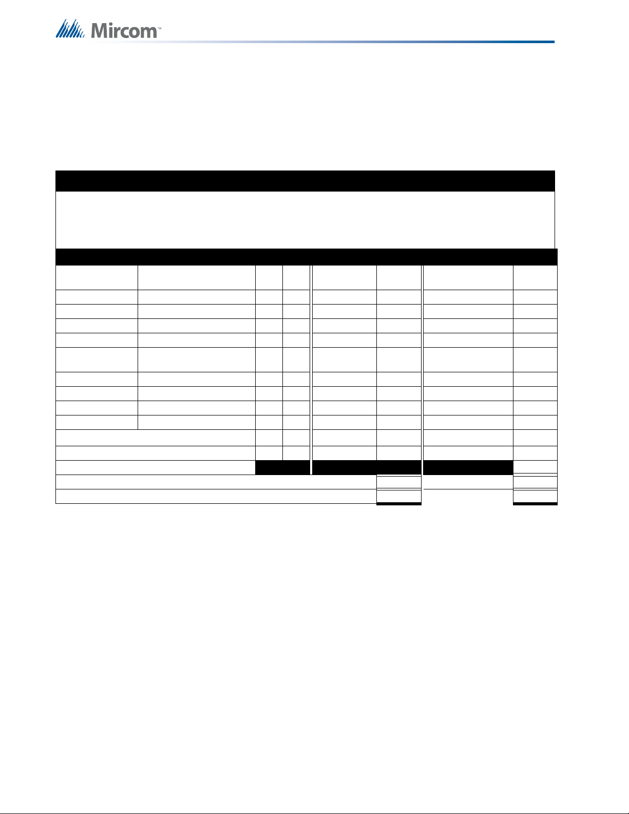
Appendix D: Power Supply and Battery Calculations
14.0 Appendix D: Power Supply and
Battery Calculations
Use the form below to determine the required main chassis and secondary power supply
(batteries).
IMPORTANT NOTICEIMPORTANT NOTICE
The main AC branch circuit connection for Fire Alarm Control Unit must provide a dedicated continuous
power without provision of any disconnect dev ice s. Use #12 AWG wire with 600-volt insulation and proper
over-current circuit protection that complies with the local codes. Refer to 13.0 Appendix C:
Specifications on page 75 for specifications.
Power Requirements (All currents are in amperes)
Model Number Description Qty Standby
MCC-1024-6(S) Main Chassis (6 amp) X 0.200 = 0.350 =
MCC-1024-12(S) Main Chassis (12 amp) X 0.200 = 0.350 =
MCC-1024-6ADS Main Chassis (6 amp) X 0.200 = 0.350 =
MCC-1024-12ADS Main Chassis (12 amp) X 0.200 = 0.350 =
ECH-1048
DM-1008A 8 initiating circuit Module X 0.080 = 0.100 =
RM-1008A 4 indicating circuit Module X 0.035 = 0.150 =
UDACT-300A Digital Communicator Mod. X 0.045 = 0.120 =
PR-300 City Tie Module X 0.035 = 0.300 =
Two-Wire Smoke Detectors
Four-Wire Smoke Detectors X = =
Signal Load (bells, horns, strobes, and etc.)
Auxiliary Power Supply for Remote Annunciators Alarm =
Total currents (Add above currents) STANDBY (A) (B)
Expander Chassis (48 Circuit
Displays)
X 0.200 = 0.020 =
♦
0.0001
Total
Standby
= * 0.090 = 0.090
Alarm
=
Total
Alarm
Total Current Requirement
ALARM (B)______ Amps.
Battery Capacity Requirement
(
[STANDBY (A) ______ ] X [(24 or 60 Hours) ___ ]) + ([ALARM (B) ______ ] X [♣Alarm in Hr.] _____) = (C) ______AH
Main Chassis Selection
Select MCC-1024-6(SA) if (B) is less than 12 Amps.
Battery Selection
Multiply (C) by 1.20 to derate battery.
Batteries: BA-110 (10AH) and BA-117(17AH) will fit in the BB-1024
BA-124(24AH) and BA-140(40AH) will fit in the BB-1072
* Assuming three initiating circuits in alarm.
♣
Use 0.084 for five minutes of alarm or 0.5 for thirty minutes of alarm as a multiplier figure.
♦
Using the MIR-525/U 2-wire smoke detector . See LT-1007 for other available smoke detectors.
80
Page 81

Warranty & Warning Information
15.0 Warranty & Warning Information
Warning Please Read Carefully
Note to End Users: This equipment is subject to terms and conditions of sale as follows:
Note to Installers
This warning contains vital information. As the only individual in contact with system users, it is
your responsibility to bring each item in this warning to the attention of the users of this
system. Failure to properly inform system end-users of the circumstances in which the system
might fail may result in over-reliance upon the system. As a result, it is imperative that you
properly inform each customer for whom you install the system of the possible forms of failure.
System Failures
This system has been carefully designed to be as effective as possible. There are
circumstances, such as fire or other types of emergencies where it may not provide pr otection.
Alarm systems of any type may be compromised deliberately or may fail to operate as
expected for a variety of reasons. Some reasons for system failure include:
•Inadequate Installation
A Fire Alarm system must be installed in accordance with all the applicable codes and
standards in order to provide adequate protection. An inspection and approval of the initial
installation, or, after any changes to the system, must be conducted by the Local Authority
Having Jurisdiction. Such inspections ensure installation has been carried out properly.
•Power Failure
Control units, smoke detectors and many other con ne cted devices re quir e an ade qu ate po wer
supply for proper operation. If the system or any device connected to the system operates
from batteries, it is possible for th e batteries to fail. Even if the batteries have no t failed, they
must be fully charged, in good condition and installed correctly. If a device operates only by
AC power, any interruption, however brief, will render that device inoperative while it does not
have power. Power interruptions of any length are often accompanied by voltage fluctuations
which may damage electronic equipment such as a fire alarm system. After a power
interruption has occurred, immediately conduct a complete system test to ensure that the
system operates as intended.
•Failure of Replaceable Batteries
Systems with wireless transmitters have been designed to provide several years of battery life
under normal conditions. The expected battery life is a function of the device environment,
usage and type. Ambient conditions such as high humidity, high or low temperatures, or large
temperature fluctuations ma y reduc e the ex pected b attery lif e. While e ach trans mitting d evice
has a low battery monitor which identifies when the batteries need to be replaced , this mon ito r
may fail to operate as expected. Regular testing and maintenance will keep the system in
good operating condition.
•Compromise of Radio Frequency (Wireless) Devices
Signals may not reach the receiver under all circumstances which could include metal objects
placed on or near the radio path or deliberate jamming or other inadvertent radio signal
interference.
•System Users
A user may not be able to operate a panic or emergency switch possibly due to permanent or
temporary physical disability, inability to reach the device in time, or unfamiliarity with the
correct operation. It is important that all system users be trained in the correct operation of the
alarm system and that they know how to respond when the system indicates an alarm.
•Automatic Alarm Initiating Devices
Smoke detectors, heat detectors and other alarm initiating devices that are a part of this
system may not properly detect a fire condition or signal the control p anel to alert occup ant s o f
a fire condition for a number of reasons, such as: the smoke detectors or heat detector may
have been improperly installed or positioned; smoke or heat may not be able to reach the
81
Page 82

Warranty & Warning Information
alarm initiating device, such as when the fire is in a chimney, walls or roofs, or on the other
side of closed doors; and, smoke and heat detectors may not detect smoke or heat from fires
on another level of the residence or building.
•Software
Most MGC products contain software. With respect to those products, MGC does not warranty
that the operation of the software will be uninterrupted or error-free or that the software will
meet any other standard of performance, or that the functions or performance of the software
will meet the user’s requirements. MGC shall not be liable for any delays, breakdowns,
interruptions, loss, destruction, alteration or other problems in the use of a product arising our
of, or caused by, the software.
Every fire is different in the amount and rate at which smoke and heat are generated. Smoke
detectors cannot sense all types of fires equally well. Smoke detectors may not provide timely
warning of fires caused by carelessness or safety hazards such as smoking in bed, violent
explosions, escaping gas, improper storage of flammable materials, overloaded electrical
circuits, children playing with matches or arson.
Even if the smoke detector or heat detector oper ates as intended, there may b e circumsta nces
when there is insufficient warning to allow all occupants to escape in time to avoid injury or
death.
•Alarm Notification Appliances
Alarm Notification Appliances such as sirens, bells, horns, or strobes may not warn people or
waken someone sleeping if there is a n intervening wall or door. If notification appliances are
located on a different level of the residence or premise, then it is less likely that the occupants
will be alerted or awakened. Audible notification appliances may be interfered with by other
noise sources such as stereos, radios, televisions, air conditioners or other appliances, or
passing traffic. Audible notification appliances, however loud, may not be heard by a hearingimpaired person.
•Telephone Lines
If telephone lines are used to transmit alarms, they may be out of service or busy for certain
periods of time. Also the telephone lines may be compromised by such things as criminal
tampering, local construction, storms or earthquakes.
•Insufficient Time
There may be circumstances when the system will operate as intended, yet the occupants will
not be protected from the emergency due to their inability to respond to the warnings in a
timely manner. If the system is monitored, the response may not occur in time enough to
protect the occupants or their belongings.
•Component Failure
Although every effort has been made to make this system as reliable as possible, the system
may fail to function as intended due to the failure of a component.
•Inadequate Testing
Most problems that would prevent an alarm system from operating as intended can be
discovered by regular testing and maintenance. The complete system should be tested as
required by national standards and the Local Authority Having Jurisdiction and immediately
after a fire, storm, earthqua ke, accident, or any kind of construction activity inside or outside
the premises. The testing should include all sensing devices, keypads, consoles, alarm
indicating devices and any other operational devices that are part of the system.
•Security and Insurance
Regardless of its capabilities, an alarm system is not a substitute for property or life insurance.
An alarm system also is not a substitute for property owners, renters, or other occupants to act
prudently to prevent or minimize the harmful effects of an emergency situation.
82
Page 83

Warranty & Warning Information
IMPORTANT NOTE: End-users of the system must take care to ensure that the system,
batteries, telephone lines, etc. are tested and examined on a regular basis to ensure the
minimization of system failure.
Limited Warranty
Mircom Technologies Ltd., MGC Systems Corp. and MGC System International Ltd. together
with their subsidiaries and affiliates (collectively, MGC) warrants the original purchaser that for
a period of three years from the date of shipment, proprietary manufactured product shall be
free of defects in materials and workmanship, under normal use. During the warranty period,
MGC shall, at its option, repair or replace any defective product upon return of the product to
its factory, at no charge for labor and m aterials. Non-proprietary, third party or OEM product
shall be warranted in accordance with the warranty period of the manufacturer. Any
replacement and/or repaired parts are warranted for the remainder of the original warranty or
ninety (90) days, whichever is longer. The original owner must promptly notify MGC in w riting
that there is defect in material or workmanship, such written notice to be received in all events
prior to expiration of the warranty period.
International Warranty
The warranty for international custom ers is the same as for any customer within Canada and
the United States, MGC shall not be responsible for any customs fees, taxes, or VAT that may
be due.
Conditions to Void Warranty
This warranty applies only to defects in parts and workmanship relating to normal use. It does
not cover:
•damage incurred in shipping or handling;
•damage caused by disaster such as fire, flood, wind, earthquake or lightning;
•damage due to causes beyo nd the control of MGC such as excessive voltage, mechanical
shock or
•water damage;
•damage caused by unauthorized attachment, alterations, modifications or foreign objects;
•damage caused by peripherals (unless such peripherals were supplied by MGC);
•defects caused by failure to provide a suitable installation environment for the products;
•damage caused by use of the products for purposes other than those for which it was
designed;
•damage from improper maintenance;
•damage arising out of any other abuse, mishandling or improper application of the products.
Warranty Procedure
To obtain service under this warranty, please return the item(s) in question to the point of
purchase. All authorized distributors and dealers have a warranty program. Anyone returning
goods to MGC must first obtain an authorization number. MGC will not accept any shipment
whatsoever for which prior authorization has not been obtained. NOTE: Unless specific preauthorization in writing is obtained from MGC management, no credits will be issued for
custom fabricated products or parts or for complete fire alarm system. MGC will at its sole
option, repair or replace parts under warranty. Advance replacements for such items must be
purchased.
83
Page 84

Warranty & Warning Information
WARNING: MGC recommends that the entire system be completely tested on a regular basis.
However, despite frequent testing, and due to, but not limited to, criminal tampering or electrical
disruption, it is possible for this product to fail to perform as expected.
NOTE: Under no circumstances shall MGC be liable for any special, incidental, or consequential
damages based upon breach of warranty, breach of contract, negligence, strict liability, or any other
legal theory. Such damages include, but are not limited to, loss of profits, loss of the product or any
associated equipment, cost of capital, cost of substitute or replacement equipment, facilities or
services, down time, purchaser’s time, the claims of third parties, including customers, and injury to
property.
MGC MAKES NO WARRANTY OF MERCHANTABILITY OR FITNESS FOR A PARTICULAR
PURPOSE WITH RESPECT TO ITS GOODS DELIVERED, NOR IS THERE ANY OTHER
WARRANTY, EXPRESSED OR IMPLIED, EXCEPT FOR THE WARRANTY CONTAINED HEREIN.
Note: MGC’s liability for failure to repair the product under this warranty after a reasonable
number of attempts will be limited to a replacement of the product, as the exclusive remedy for
breach of warranty.
Disclaimer of Warranties
This warranty contains the entire warranty and shall be in lieu of any and all other warranties,
whether expressed or implied (including all implied warranties of merchantability or fitness for
a particular purpose) and of all other obligations or liabilities. MGC neither assumes nor
authorizes any other person purporting to act on its behalf to modify or to change this
warranty, or to assume for it any other warranty or liability concerning this product.
This disclaimer of warranties and limited warranty are governed by the laws of the province of
Ontario, Canada.
Out of Warranty Repairs
MGC will at its option repair or replace out-of-warranty products which are returned to its
factory according to the following conditions. Anyone returning goods to MGC must first obtain
an authorization number. MGC will not accept any shipment whatsoever for which prior
authorization has not been obtained.
Products which MGC determines to be repairable will be repaired and returned. A set fee
which MGC has predetermined and which may be revised from time to time, will be charged
for each unit repaired.
Products which MGC determines not to be repairable will be replaced by the nearest
equivalent product available at that time. The current market price of the replacement product
will be charged for each replacement unit.
The foregoing information is accu rate as of th e date of publis hing and is su bject to change or
revision without prior notice at the sole discretion of the Company
84
Page 85

Page 86

Page 87

Page 88

CANADA - Main Office
25 Interchange Way
Vaughan, ON L4K 5W3
Tel: (888) 660-4655
(905) 660-4655
Fax: (905) 660-4113
U.S.A
4575 Witmer Industrial Estates
Niagara Falls, NY 14305
Tel: (888) 660-4655
(905) 660-4655
Fax: (905) 660-4113
TECHNICAL SUPPORT
North America
Tel: (888) Mircom5
(888) 647-2665
International
Tel: (905) 647-2665
© Mircom 2016
Printed in Canada
Subject to change without prior notice
www.mircom.com
 Loading...