

Page 1
EC-300
Audible Visual Emergency Call System
Installation and Operation Manual
LT-368 Rev. 2
September 2012
Page 2

Page 3

Table of Contents
1.0 Introduction 5
2.0 Installation 6
2.1 Patient Station ................................................................................................................ 6
2.1.1 EC-100 Pull Cord Station ............................................................................................... 6
2.1.2 EC-103 Pull Cord Station with LED ............................................................................... 6
2.2 Emergency Station ......................................................................................................... 6
2.3 Corridor Lamps (Dome Lights) ....................................................................................... 6
2.3.1 EC-104 Dome Light ....................................................................................................... 6
2.3.2 EC-106 Dual Dome Light ............................................................................................... 6
2.4 Central Nurse’s Station .................................................................................................. 6
2.4.1 EC-300 Call Receiver Panel .......................................................................................... 7
2.4.2 EC-220A Annunciator Panel .......................................................................................... 7
2.4.3 EC-240A Annunciator Panel .......................................................................................... 7
2.4.4 EC-000 Blank Panel ....................................................................................................... 7
2.4.5 TR-074B Transformer, 24 VAC, 75 VA .......................................................................... 7
2.5 Other Devices ................................................................................................................ 7
2.5.1 EC-105A Corridor Horn .................................................................................................. 7
2.5.2 EC-140 Dome Alarm ...................................................................................................... 7
2.6 EC-300 Call Receiver Panel .......................................................................................... 8
2.6.1 Terminals ....................................................................................................................... 8
2.6.2 Call Back Feature .......................................................................................................... 8
2.6.3 Jumpers and Specifications ........................................................................................... 8
2.6.4 Power Consumption Chart ............................................................................................. 8
3.0 System Operation 9
3.1 Standard Visual Call ...................................................................................................... 9
3.1.1 Products Required ......................................................................................................... 9
3.1.2 Operation ....................................................................................................................... 9
3.2 Distinguishable Alarm States, Normal And Emergency ................................................. 11
3.2.1 Products Required ......................................................................................................... 11
3.2.2 Operation ....................................................................................................................... 11
3.3 Normal And Emergency Call With Subsequent Alarm ................................................... 13
3.3.1 Products Required ......................................................................................................... 13
3.3.2 Operation ....................................................................................................................... 13
3.4 Subsequent Alarm Using EC-103 And EC-115 Stations ............................................... 15
3.4.1 Products Required ......................................................................................................... 15
3.4.2 Operation ....................................................................................................................... 15
4.0 Warranty & Warning Information 17
3
Page 4

List of Figures
Figure 1 EC-300 Call Receiver Panel Receiver Panel ................................................................. 8
Figure 2 Non-Subsequent Single State Alarm Using EC-100 Suite Stations ............................... 10
Figure 3 Non-Subsequent Single State Alarm Using EC-100 Room Stations ............................. 12
Figure 4 Normal and Emergency Call with Subsequent Alarm .................................................... 14
Figure 5 Subsequent Alarm Using EC-103 and EC-115 Stations ................................................ 16
4
Page 5

1.0 Introduction
The Mircom EC-300 Emergency Call System provides the common features and functions
demanded by engineers and contractors. Over the years, nurse call systems have become
increasingly complicated and expensive. Mircom’s EC-300 system offers a basic system most
nurses and administrators feel is necessary.
• The EC-300 has been designed for easy operation so few instructions are required for
staff to learn and essentially no training is required.
• All “Emergency Calls” are indicated by a fast pulsing audible/visual indication which
overrides “Normal” calls of slow pulsing audible/visual indications. All calls can only be
cancelled at the point of activation. The nurse’s station shall be able to momentarily
silence for periods of 10, 5, or 2.5 minutes.
• Easy maintenance is obtained on the Mircom system due to its modular construction. All
components including the annunciator panels consists of modular panels for fast
servicing and trouble-shooting.
• Reliable, solid state construction on the EC-300 system provides trouble-free usage.
The audible alarms are solid statet for long term reliability unlike electro-mechanical
devices such as buzzers or chimes. All annunciator lights are long life, high intensity,
wide angle, light emitting diodes (LEDs).
• Flexibility of the system is easy, due to the modular construction. The Emergency Call
system and Door Monitoring can often be combined into the same housing. Blank
panels can be provided to be replaced in any future expansion.
• System components on a typical system usually include patient stations, emergency
stations, corridor lights and central nurse’s station. This manual will outline each and
their various functions.
5
Page 6

2.0 Installation
Before any wiring is done to the system components, check all wires for opens, shorts or
grounds, using an ohmmeter.
2.1 Patient Station
The EC-100 or EC-103 Pull Cord Station are normally mounted next to the patient’s bed. All
stations have a brushed stainless finish.
2.1.1 EC-100 Pull Cord Station
The pull cord station is equipped with a 6 foot, white nylon cord easily cut to required lengths.
These cords when pulled operate a switch at the cord station. To reset the patient call, move
the switch (at the pull cord station) to the upward position. Use this station in non-subsequent
alarm systems.
2.1.2 EC-103 Pull Cord Station with LED
The pull cord station is equipped with a 6 foot, white nylon cord and a red confirmation LED.
The cords when pulled operate a switch at the station which triggers the LED to illuminate. To
reset the patient call, move the switch (at the pull cord station) to the upward position.
2.2 Emergency Station
By wiring configuration of the EC-103 Pull Cord Station, the station can be programmed for
“Emergency” status calls.
2.3 Corridor Lamps (Dome Lights)
The Corridor lamps are normally mounted above the doors of all rooms equipped with any
type of station. The corridor lamps have a brushed stainless steel finish with a white plastic
wedge shape lens. The lamps mount onto a standard single gang electrical box. Pressing the
lens on top and bottom will unhook the lens from the plate. Replacement bulbs; use #1820,
24V.
2.3.1 EC-104 Dome Light
The EC-104 is equipped with one clear incandescent bulb. The light illuminates whenever the
suite station initiates a call to provide a visual signal in the corridor.
2.3.2 EC-106 Dual Dome Light
The EC-106 is equipped with two clear incandescent bulbs divided by a barrier strip, top and
bottom. The top light illuminates whenever an Emergency station initiates a call. (Consult our
factory, if coloured bulbs are required)
2.4 Central Nurse’s Station
The Central Nurses’ Console is normally located within easy reach of operating personnel.
The console houses the
6
Page 7

central control and annunciator panels. The console can either be flush or surface mounted.
i
Each console consists of a backbox, frame, modular annunciator panels and the central call
receiver panel.
Note: When local bylaws do not allow audible patient calls to be silenced at the
console, the ‘disable silence’ jumper must be cut on the EC-300 Call Receiver
Panel.
All console modular panels are made from extruded aluminum and secured to the 300 Series
frame by two screws.
The following are the available console panels.
2.4.1 EC-300 Call Receiver Panel
The EC-300 is the electronic central control board. All wiring is terminated to this panel
excluding the selective room wiring which terminates on the annunciator panels. Connections
are made to the EC-300 to determine the type of system operation and various flash rates. All
peripheral devices such as Corridor horns and Duty stations terminate to the EC-300.
2.4.2 EC-220A Annunciator Panel
The EC-220A has 20 red LEDs to annunciate suite alarms. Each LED has a directory which
can be typed with the room number.
2.4.3 EC-240A Annunciator Panel
The EC-240A has 40 red LEDs to annunciate suite alarms. Each LED has a directory which
can be typed with the room number.
2.4.4 EC-000 Blank Panel
Ideal for installations which are built in phases. The EC-000 accommodates one standard
panel space which can be replaced in the future with an annunciator.
2.4.5 TR-074B Transformer, 24 VAC, 75 VA
The TR-074B is a low voltage transformer used for all the power requirements of the EC-300
system.
2.5 Other Devices
2.5.1 EC-105A Corridor Horn
The EC-105A is a 24 Volt AC/DC horn to audibly annunciate alarm calls. Made from brushed
stainless steel, the EC-105A mounts onto a standard two gang electrical box.
2.5.2 EC-140 Dome Alarm
The EC-140 mounts onto a single gang electrical box. Made from brushed stainless steel, the
Corridor lamp includes a 24 V DC electronic piezo.
7
Page 8
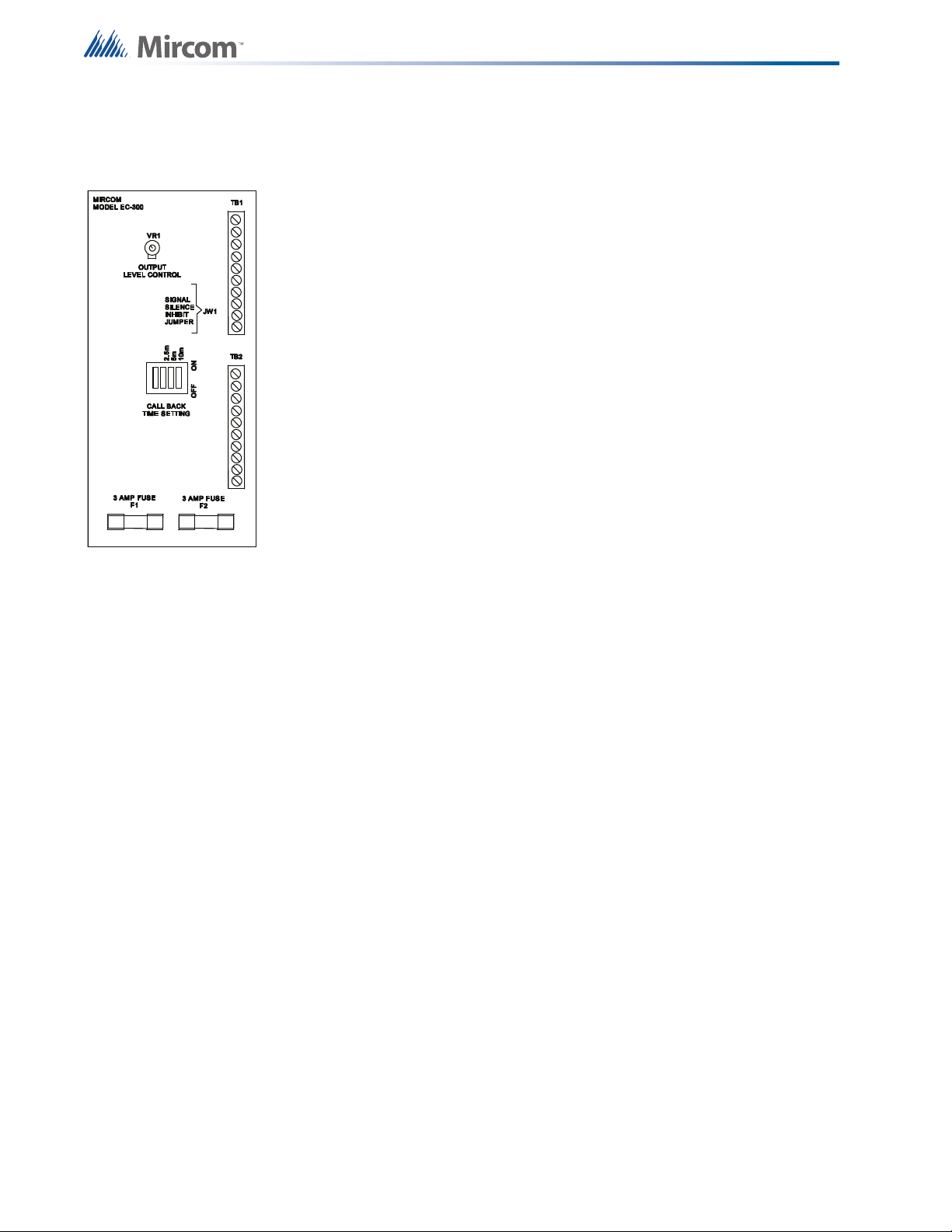
2.6 EC-300 Call Receiver Panel
2.6.1 Terminals
Figure 1
EC-300 Call Receiver
Panel Receiver Panel
L1
FL1
FL2
FL3
FL4
TRIG
+
-
T1,T2
+
-
Z1, Z2
RT
RR
RA
Current sense input, used on non-subsequent alarm installations.
CAUTION: Do not connect this terminal directly to ground.
Slow flashing tripper input.
Slow flashing output (normally closed) contact which is connected to
ground.
Fast flashing trigger input.
Fast flashing output (normally closed) contact which is connected to
ground.
Trigger input for ‘subsequent’ alarm systems. Only EC-103 pull cord
stations can use this input.
Positive 24 volt output for peripheral devices.
Negative 24 volt output for peripheral devices.
Power supply input, 24 V AC
SPK
SPK External speaker outputs for duty stations.
Normally open SPST contact for exterior devices. Rated at 3 amperes, 24
volts. Contact releases on ‘Signal Silence’.
Remote Alarm output which can be silenced.
Remote Reset input to remotely silence the EC-300 system.
Remote Alarm output which cannot be silenced until all alarm conditions
haave been reset.
2.6.2 Call Back Feature
2.6.3 Jumpers and Specifications
VR1
JW1
Call Back
F1 and F2
2.6.4 Power Consumption Chart
To prevent staff from forgetting a call previously silenced, a time-out call back feature is
available. A selectable DIP switch on the EC-300 Call Receiver board will re-activate the
audible alarm within 2.5, 5 or 10 minutes.
This controls the volume output to the internal/external speaker.
With jumper in, alarm tones can be silenced.
With jumper removed, alarm tones can not be silenced.
Select only one setting at a time; 2.5m, 5m or 10m which represents a call back duration of 2.5 , 5
or 10 minutes respectively. This control will re-activate the alarm tones after the pre-selected time
delay has expired.
Control unit fuses. replace only with maximum 3 amp, 250v type
ITEM VA
EC-300 Call Receiver 4
EC-104 Dome Light 4
EC-220/240 Each Illuminated LED 0
EC-105DC Horn 5
8
Page 9

3.0 System Operation
Various system operations are obtainable with the EC-300 control. Typical system drawings
are attached for the common installations. Consult our Application Engineering department for
system operations not outlined in this manual.
3.1 Standard Visual Call
3.1.1 Products Required
EC-100 Pull Cord Station
EC-104 Corridor Lamp
EC-300 Call Receiver Panel
EC-220A 20 LED Annunciator Panel
EC-240A 40 LED Annunciator Panel
PS-3B Transformer, 8/16/24 Volt taps
300-nF Frame
300-nB Backbox
3.1.2 Operation
A Pull Cord Station (Model EC-100) when pulled, will activate its corresponding Corridor Dome
Lamp (EC-104), annunciator LED and the audible alarm on the Call Reciver Panel (EC-300)
The visual and audible pulse rate can be selected by connecting ‘line 1' to FL1 (Slow Flash),
FL3 (Fast Flash) or - (Steady).
All incoming calls can be silenced from the central EC-300 call receiver panel. Subsequent
calls without being reset, will not re-activate the audible alarm. All calls must be reset before
the audible alarm will re-activate. To reset a call, the pull cord station must be placed in its
original position, by pushing the call switch up. No calls can be reset at the central monitoring
location without verifying the call.
9
Page 10

10
Figure 2 Non-Subsequent Single State Alarm Using EC-100 Suite Stations
Page 11

3.2 Distinguishable Alarm States, Normal And Emergency
3.2.1 Products Required
EC-100 Pull Cord Station
EC-104 Corridor Lamp
EC-300 Call Receiver Panel
EC-220A 20 LED Annunciator Panel
EC-240A 40 LED Annunciator Panel
PS-3B Transformer, 8/16/24 Volt tap
300-nF Frame
300-nB Backbox
3.2.2 Operation
A ‘normal’ patient call will flash the room Corridor and annunciator lamp at a slow rate. A
corresponding audible tone will be heard at the EC-300 Call receiver panel.
An ‘emergency’ patient call will flash the room Corridor and annunciator lamp at a fast rate. A
corresponding audible tone will be heard at the EC-300 Call receiver panel. All ‘emergency’
patient calls in the same room will override ‘normal’ calls.
All incoming calls can be silenced from the central EC-300 call receiver panel. Subsequent
calls without being reset, will not re-activate the audible alarm. All calls must be reset before
the audible alarm will re-activate. To reset a call, the pull cord station must be placed in its
original position, by pushing upwards the call switch. No calls can be reset at the central
monitoring location without verifying the call.
11
Page 12

12
Figure 3 Non-Subsequent Single State Alarm Using EC-100 Room Stations
Page 13

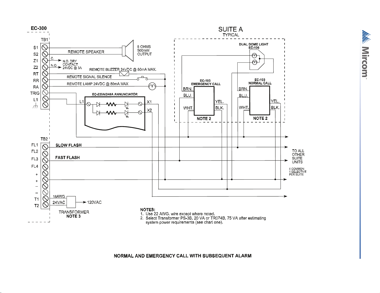
3.3 Normal And Emergency Call With Subsequent Alarm
3.3.1 Products Required
EC-103 Pull Cord Station with Confirmation LED
EC-106 Corridor Lamp with two lamps
EC-300 Call Receiver Panel
EC-220A 20 LED Annunciator Panel
EC-240A 40 LED Annunciator Panel
PS-3B Transformer, 3/16/24
300-nF Frame
300-nB Backbox
3.3.2 Operation
A ‘normal’ patient call will flash the room Corridor and annunciator lamp at a slow rate. A
corresponding audible tone will be heard at the EC-300 Call receiver panel.
An ‘emergency’ patient call will flash the room Corridor and annunciator lamp at a fast rate. A
corresponding audible tone will be heard at the EC-300 Call receiver panel. All ‘emergency’
patient calls in the same room will be distinguishable by the faster audible and visual pulse
rate.
All incoming calls can be silenced from the central EC-300 call receiver panel. Subsequent
calls will re-activate the audible alarm, without being reset. To reset a call, the pull cord station
must be placed in its original position, by pushing the call switch up. No calls can be reset at
the central monitoring location without verifying the call.
13
Page 14
14
Figure 4 Normal and Emergency Call with Subsequent Alarm
Page 15

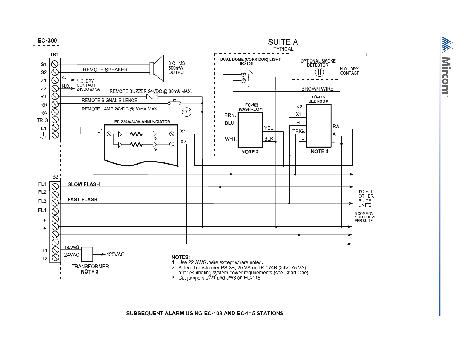
3.4 Subsequent Alarm Using EC-103 And EC-115 Stations
3.4.1 Products Required
EC-103 Pull Cord Station with Confirmation LED
EC-115 Bedroom Station
EC-106 Corridor Lamp with two lamps
EC-300 Call Receiver Panel
EC-220A 20 LED Annunciator Panel
EC-240A 40 LED Annunciator Panel
PS-3B Transformer, 3/16/24
300-nF Frame
300-nB Backbox
3.4.2 Operation
A ‘normal’ patient call will flash the room Corridor and annunciator lamp at a slow rate. A
corresponding audible tone will be heard at the EC-300 Call receiver panel.
An ‘emergency’ patient call will flash the room Corridor and annunciator lamp at a fast rate. A
corresponding audible tone will be heard at the EC-300 Call receiver panel. All ‘emergency’
patient calls in the same room will be distinguishable by the faster audible and visual pulse
rate.
All incoming calls can be silenced from the central EC-300 call receiver panel. Subsequent
calls will re-activate the audible alarm, without being reset. To reset a call, the pull cord station.
must be placed in its original position, by pushing the call switch up. No calls can be reset at
the central monitoring location without verifying the call.
15
Page 16
16
Figure 5 Subsequent Alarm Using EC-103 and EC-115 Stations
Page 17

4.0 Warranty & Warning Information
Warning Please Read Carefully
Note to End Users: This equipment is subject to terms and conditions of sale as follows:
Note to Installers
This warning contains vital information. As the only individual in contact with system users, it is
your responsibility to bring each item in this warning to the attention of the users of this
system. Failure to properly inform system end-users of the circumstances in which the system
might fail may result in over-reliance upon the system. As a result, it is imperative that you
properly inform each customer for whom you install the system of the possible forms of failure.
System Failures
This system has been carefully designed to be as effective as possible. There are
circumstances, such as fire or other types of emergencies where it may not provide protection.
Alarm systems of any type may be compromised deliberately or may fail to operate as
expected for a variety of reasons. Some reasons for system failure include:
•Inadequate Installation
A Fire Alarm system must be installed in accordance with all the applicable codes and
standards in order to provide adequate protection. An inspection and approval of the initial
installation, or, after any changes to the system, must be conducted by the Local Authority
Having Jurisdiction. Such inspections ensure installation has been carried out properly.
•Power Failure
Control units, smoke detectors and many other connected devices require an adequate power
supply for proper operation. If the system or any device connected to the system operates
from batteries, it is possible for the batteries to fail. Even if the batteries have not failed, they
must be fully charged, in good condition and installed correctly. If a device operates only by
AC power, any interruption, however brief, will render that device inoperative while it does not
have power. Power interruptions of any length are often accompanied by voltage fluctuations
which may damage electronic equipment such as a fire alarm system. After a power
interruption has occurred, immediately conduct a complete system test to ensure that the
system operates as intended.
•Failure of Replaceable Batteries
Systems with wireless transmitters have been designed to provide several years of battery life
under normal conditions. The expected battery life is a function of the device environment,
usage and type. Ambient conditions such as high humidity, high or low temperatures, or large
temperature fluctuations may reduce the expected battery life. While each transmitting device
has a low battery monitor which identifies when the batteries need to be replaced, this monitor
may fail to operate as expected. Regular testing and maintenance will keep the system in
good operating condition.
•Compromise of Radio Frequency (Wireless) Devices
Signals may not reach the receiver under all circumstances which could include metal objects
placed on or near the radio path or deliberate jamming or other inadvertent radio signal
interference.
•System Users
A user may not be able to operate a panic or emergency switch possibly due to permanent or
temporary physical disability, inability to reach the device in time, or unfamiliarity with the
correct operation. It is important that all system users be trained in the correct operation of the
alarm system and that they know how to respond when the system indicates an alarm.
•Automatic Alarm Initiating Devices
Smoke detectors, heat detectors and other alarm initiating devices that are a part of this
system may not properly detect a fire condition or signal the control panel to alert occupants of
a fire condition for a number of reasons, such as: the smoke detectors or heat detector may
17
Page 18

have been improperly installed or positioned; smoke or heat may not be able to reach the
alarm initiating device, such as when the fire is in a chimney, walls or roofs, or on the other
side of closed doors; and, smoke and heat detectors may not detect smoke or heat from fires
on another level of the residence or building.
•Software
Most MGC products contain software. With respect to those products, MGC does not warranty
that the operation of the software will be uninterrupted or error-free or that the software will
meet any other standard of performance, or that the functions or performance of the software
will meet the user’s requirements. MGC shall not be liable for any delays, breakdowns,
interruptions, loss, destruction, alteration or other problems in the use of a product arising our
of, or caused by, the software.
Every fire is different in the amount and rate at which smoke and heat are generated. Smoke
detectors cannot sense all types of fires equally well. Smoke detectors may not provide timely
warning of fires caused by carelessness or safety hazards such as smoking in bed, violent
explosions, escaping gas, improper storage of flammable materials, overloaded electrical
circuits, children playing with matches or arson.
Even if the smoke detector or heat detector operates as intended, there may be circumstances
when there is insufficient warning to allow all occupants to escape in time to avoid injury or
death.
•Alarm Notification Appliances
Alarm Notification Appliances such as sirens, bells, horns, or strobes may not warn people or
waken someone sleeping if there is an intervening wall or door. If notification appliances are
located on a different level of the residence or premise, then it is less likely that the occupants
will be alerted or awakened. Audible notification appliances may be interfered with by other
noise sources such as stereos, radios, televisions, air conditioners or other appliances, or
passing traffic. Audible notification appliances, however loud, may not be heard by a hearingimpaired person.
•Telephone Lines
If telephone lines are used to transmit alarms, they may be out of service or busy for certain
periods of time. Also the telephone lines may be compromised by such things as criminal
tampering, local construction, storms or earthquakes.
18
•Insufficient Time
There may be circumstances when the system will operate as intended, yet the occupants will
not be protected from the emergency due to their inability to respond to the warnings in a
timely manner. If the system is monitored, the response may not occur in time enough to
protect the occupants or their belongings.
•Component Failure
Although every effort has been made to make this system as reliable as possible, the system
may fail to function as intended due to the failure of a component.
•Inadequate Testing
Most problems that would prevent an alarm system from operating as intended can be
discovered by regular testing and maintenance. The complete system should be tested as
required by national standards and the Local Authority Having Jurisdiction and immediately
after a fire, storm, earthquake, accident, or any kind of construction activity inside or outside
the premises. The testing should include all sensing devices, keypads, consoles, alarm
indicating devices and any other operational devices that are part of the system.
•Security and Insurance
Regardless of its capabilities, an alarm system is not a substitute for property or life insurance.
An alarm system also is not a substitute for property owners, renters, or other occupants to act
prudently to prevent or minimize the harmful effects of an emergency situation.
Page 19

IMPORTANT NOTE: End-users of the system must take care to ensure that the system,
batteries, telephone lines, etc. are tested and examined on a regular basis to ensure the
minimization of system failure.
Limited Warranty
Mircom Technologies Ltd., MGC Systems Corp. and MGC System International Ltd. together
with their subsidiaries and affiliates (collectively, MGC) warrants the original purchaser that for
a period of three years from the date of shipment, proprietary manufactured product shall be
free of defects in materials and workmanship, under normal use. During the warranty period,
MGC shall, at its option, repair or replace any defective product upon return of the product to
its factory, at no charge for labor and materials. Non-proprietary, third party or OEM product
shall be warranted in accordance with the warranty period of the manufacturer. Any
replacement and/or repaired parts are warranted for the remainder of the original warranty or
ninety (90) days, whichever is longer. The original owner must promptly notify MGC in writing
that there is defect in material or workmanship, such written notice to be received in all events
prior to expiration of the warranty period.
International Warranty
The warranty for international customers is the same as for any customer within Canada and
the United States, MGC shall not be responsible for any customs fees, taxes, or VAT that may
be due.
Conditions to Void Warranty
This warranty applies only to defects in parts and workmanship relating to normal use. It does
not cover:
•damage incurred in shipping or handling;
•damage caused by disaster such as fire, flood, wind, earthquake or lightning;
•damage due to causes beyond the control of MGC such as excessive voltage, mechanical
shock or
•water damage;
•damage caused by unauthorized attachment, alterations, modifications or foreign objects;
•damage caused by peripherals (unless such peripherals were supplied by MGC);
•defects caused by failure to provide a suitable installation environment for the products;
•damage caused by use of the products for purposes other than those for which it was
designed;
•damage from improper maintenance;
•damage arising out of any other abuse, mishandling or improper application of the products.
Warranty Procedure
To obtain service under this warranty, please return the item(s) in question to the point of
purchase. All authorized distributors and dealers have a warranty program. Anyone returning
goods to MGC must first obtain an authorization number. MGC will not accept any shipment
whatsoever for which prior authorization has not been obtained. NOTE: Unless specific preauthorization in writing is obtained from MGC management, no credits will be issued for
custom fabricated products or parts or for complete fire alarm system. MGC will at its sole
option, repair or replace parts under warranty. Advance replacements for such items must be
purchased.
19
Page 20

Note: MGC’s liability for failure to repair the product under this warranty after a reasonable
WARNING: MGC recommends that the entire system be completely tested on a regular basis.
However, despite frequent testing, and due to, but not limited to, criminal tampering or electrical
disruption, it is possible for this product to fail to perform as expected.
NOTE: Under no circumstances shall MGC be liable for any special, incidental, or consequential
damages based upon breach of warranty, breach of contract, negligence, strict liability, or any othe
legal theory. Such damages include, but are not limited to, loss of profits, loss of the product or any
associated equipment, cost of capital, cost of substitute or replacement equipment, facilities or
services, down time, purchaser’s time, the claims of third parties, including customers, and injury to
property.
MGC MAKES NO WARRANTY OF MERCHANTABILITY OR FITNESS FOR A PARTICULAR
PURPOSE WITH RESPECT TO ITS GOODS DELIVERED, NOR IS THERE ANY OTHER
WARRANTY, EXPRESSED OR IMPLIED, EXCEPT FOR THE WARRANTY CONTAINED HEREIN
number of attempts will be limited to a replacement of the product, as the exclusive remedy for
breach of warranty.
Disclaimer of Warranties
This warranty contains the entire warranty and shall be in lieu of any and all other warranties,
whether expressed or implied (including all implied warranties of merchantability or fitness for
a particular purpose) and of all other obligations or liabilities. MGC neither assumes nor
authorizes any other person purporting to act on its behalf to modify or to change this
warranty, or to assume for it any other warranty or liability concerning this product.
This disclaimer of warranties and limited warranty are governed by the laws of the province of
Ontario, Canada.
Out of Warranty Repairs
MGC will at its option repair or replace out-of-warranty products which are returned to its
factory according to the following conditions. Anyone returning goods to MGC must first obtain
an authorization number. MGC will not accept any shipment whatsoever for which prior
authorization has not been obtained.
Products which MGC determines to be repairable will be repaired and returned. A set fee
which MGC has predetermined and which may be revised from time to time, will be charged
for each unit repaired.
Products which MGC determines not to be repairable will be replaced by the nearest
equivalent product available at that time. The current market price of the replacement product
will be charged for each replacement unit.
The foregoing information is accurate as of the date of publishing and is subject to change or
revision without prior notice at the sole discretion of the Company
20
Page 21

Page 22

Page 23

Page 24

CANADA - Main Office
25 Interchange Way
Vaughan, ON L4K 5W3
Tel: (888) 660-4655
(905) 660-4655
Fax: (905) 660-4113
U.S.A
4575 Witmer Industrial Estates
Niagara Falls, NY 14305
Tel: (888) 660-4655
(905) 660-4655
Fax: (905) 660-4113
TECHNICAL SUPPORT
North America
Tel: (888) Mircom5
(888) 647-2665
International
Tel: (905) 647-2665
© Mircom 2012
Printed in Canada
Subject to change without prior notice
www.mircom.com
 Loading...