

Page 1
DTC-300A
Digital Transmitter Communicator
LT-889 Rev.1
October 2006
Installation and Operation Manual
A
sn
oi
t
u
l
o
S
y
te
f
aS
e
f
i
L
de
c
n
av
d
A
00
3
-C
TD
R
E
T
A
C
I
N
U
M
M
O
C
R
E
T
T
I
MS
N
AR
T L
A
TI
G
I
D
NO
R
E
W
O
P
Page 2

Page 3

DTC-300A DACT Dialer Installation and Operation Instructions
Contents
Industry Canada and FCC Notice ........................................................................................... 1
Introduction and Features....................................................................................................... 2
Mechanical Installation and Dimensions ............................................................................... 3
Connections and Settings....................................................................................................... 4
DTC-300A MAIN BOARD ..................................................................................................... 4
Field Wiring............................................................................................................................... 6
DTC-300A MAIN BOARD TELEPHONE WIRING ................................................................ 6
Field Wiring (continued) .......................................................................................................... 7
DTC-300A MAIN BOARD INPUT ZONE WIRING ................................................................ 7
TROUBLE OUTPUT WIRING ............................................................................................... 8
POWER SUPPLY WIRING................................................................................................... 9
Power Up Procedures.............................................................................................................. 9
Basic Operation and Supervision........................................................................................... 10
Configuration Set-up ............................................................................................................... 10
CONFIGURATION VIA ON-BOARD KEYPAD ..................................................................... 10
CONFIGURATION VIA UIMA AND COMPUTER(LOCAL):.................................................. 10
CONFIGURATION VIA MODEM AND COMPUTER(REMOTE): ......................................... 11
Keypad Configuration & Operation ........................................................................................ 12
Entering the Passcode.......................................................................................................... 12
Command Menu ................................................................................................................... 13
1.View Event Log (Command-Menu).................................................................................... 13
2. Clear Event Log (Command-Menu) .................................................................................. 14
3. Test Dialer (Command-Menu) .......................................................................................... 15
4. Config Info (Command-Menu) .......................................................................................... 17
5. Version Info....................................................................................................................... 17
6. Set Time (Command-Menu) ............................................................................................. 17
7. Set Password (Command-Menu)...................................................................................... 18
8. Default Config (Command-Menu) ..................................................................................... 19
9. Dialer Config (Command-Menu) ....................................................................................... 19
10. Input Config..................................................................................................................... 24
11. Exit .................................................................................................................................. 24
Compatible Fire Alarm Control Panels .................................................................................. 27
Compatible Receivers.............................................................................................................. 27
Specifications........................................................................................................................... 28
Battery Calculations ................................................................................................................ 28
Warranty & Warning Information............................................................................................ 29
Warning Please Read Carefully............................................................................................ 29
Limited Warranty................................................................................................................... 31
Warranty Procedure.............................................................................................................. 31
Disclaimer of Warranties....................................................................................................... 31
Out of Warranty Repairs ....................................................................................................... 32
i
Page 4

Contents
ii
Page 5

DTC-300A DACT Dialer Installation and Operation Instructions
Industry Canada and FCC Notice
Notice for all DTC-300A Sold in the U.S.A.
Note: The Ringer Equivalence Number (REN) for this product is X.X.
Mircom's DTC-300A Digital Communicator described in this manual is listed by Underwriters Laboratories Inc.
(ULI) under Standard 864 (Control Units for Fire Protective Signalling Systems). These Communicators comply with
the National Fire Protection Association (NFPA) performance requirements for DACTs and should be installed in
accordance with NFPA 72 Chapter 4 (Supervising Station Fire Alarm System). These Communicators should be
installed in accordance with this manual; the National Electrical Code (NFPA 70); and/or the local Authority Having
Jurisdiction (AHJ).
FCC Notice
This equipment complies with the Federal Communications Commission (FCC) rules and regulations governing
telephone equipment and the Technical Requirements for Connection to the Telephone Network published by the
industry’s Administrative Council for Terminal Attachments (ACTA). On the door of this equipment is a label that
contains, among other information, a product identifier in the format US:XXXXXXXXDTC-300A. If requested, this
number must be provided to the telephone company. This equipment is capable of seizing the line. This capability is
provided in the hardware.
The Ringer Equivalence Number (REN) assigned to each terminal device provides an indication of the maximum
number of devices that may be connected to a telephone line. Excessive REN’s on a telephone line may result in
the devices not ringing in response to an incoming call. In most, but not all areas, the sum of REN’s should not
exceed five (5.0). To be certain of the number of devices that may be connected to a line, as determined by the
total REN’s contact the local telephone company. The REN for this product is X.X.
Telephone Company Procedures: The goal of the telephone company is to provide you with the best service it
can. In order to do this, it may occasionally be necessary for them to make changes in their equipment, operations
or procedures. If these changes might affect your service or the operation of your equipment, the telephone
company will give you notice, in writing, to allow you to make any changes necessary to maintain uninterrupted
service.
In certain circumstances, it may be necessary for the telephone company to request information from you
concerning the equipment which you have connected to your telephone line. Upon request of the telephone
company, provide the FCC registration number and the ringer equivalence number (REN); both of these items are
listed on the equipment label. The sum of all of the REN’s on your telephone lines should be less than five in order
to assure proper service from the telephone company. In some cases, a sum of five may not be usable on a given
line.
If Problems Arise: If any of your telephone equipment is not operating properly, you should immediately remove it
from your telephone line, as it may cause harm to the telephone network. If the telephone company notes a
problem, they may temporarily discontinue service. When practical, they will notify you in advance of this
disconnection. If advance notice is not feasible, you will be notified as soon as possible. When you are notified, you
will be given the opportunity to correct the problem and informed of your right to file a complaint with the FCC.
Contact your telephone company if you have any questions about your phone line. In the event repairs are ever
needed on the Communicator, they should be performed by Mircom Technologies Ltd. or an authorized
representative of Mircom Technologies Ltd. For information contact Mircom Technologies Ltd. at the address and
phone numbers shown on the back page of this document.
1
Page 6

Introduction and Features
Introduction and Features
The DTC-300A is a single board Digital Communicator (DACT) that can connect to any Fire Alarm Control Panel
(FACP). It can transmit Alarm, Supervisory, Waterflow Alarm, Common Trouble, AC power trouble and Battery
Trouble information on two telephone lines to a Digital Alarm Communicator Receiver (DACR).
Features:
• Scans up to 6 configurable input zones. The input zone type may be alarm, waterflow alarm, supervisory,
trouble, AC trouble or Battery trouble.
• Reports to a DACR using Ademco Contact ID or SIA DCS reporting protocols.
• The DTC-300A has the ability of disconnecting the incoming and outgoing calls and capturing the line for
transmission to the DACR.
• Provides telephone line monitoring and reports status via LED indication on-board.
• Provides LED indication for AC Power, Common Trouble, CPU Fail and Ground Fault.
• User configurable locally with on-board keypad and a CFG-300 Configuration Tool or using a UIMA and
computer with serial port or USB. Remotely configurable via a personal computer, modem and telephone line
connection.
• Provides event logs of 500 entries each to save events from local dialer or remote fire alarm panel. These logs
can be reviewed locally with the CFG-300 Configuration Tool or remotely via modem.
• Requires 24V DC filtered or 24V DC Full Wave Rectified (FWR) power supply.
2
Page 7
DTC-300A DACT Dialer Installation and Operation Instructions
Mechanical Installation and Dimensions
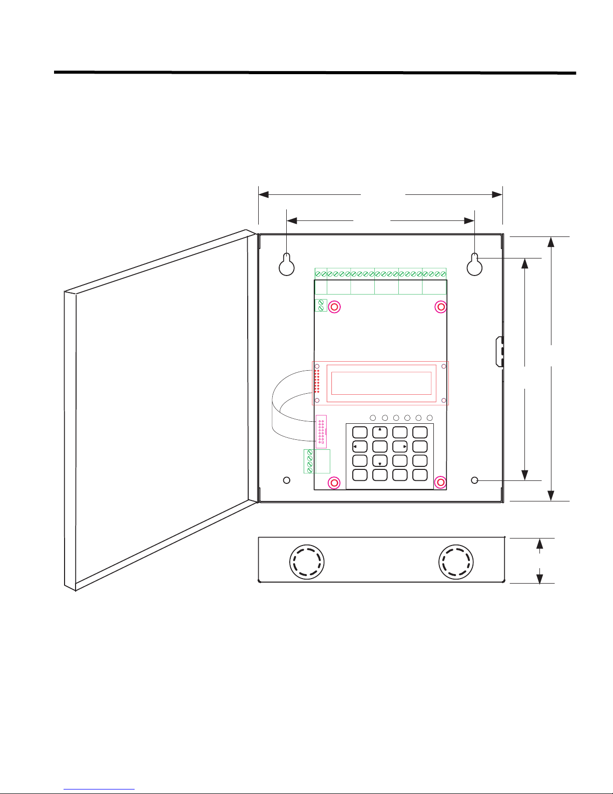
The DTC-300A board is a single PCB assembly. It comes mounted in a 8.25” wide by 9” high by 1.5” deep box.
There are four mounting holes, two at the top and two at the bottom, see Figure 1 below for mounting hole location
and backbox dimensions. There are two conduit holes at the top of the box and two conduit holes at the bottom of
the box.
Figure 1: DTC-300A Backbox Dimensions for Mounting
8 1/4”
6 5/16"
0RXQWLQJ+ROHV [
&)* &21 ),*85 $7, 21 722/
1
2
ABC3DEF
4
596
GHI
7
PRS
*
MNO
JKL
8
WXY
TUV
#
0
QZ
TOP AND BOTTOM
9"
7 1/2”
EN TER
MENU
CANCEL
INFO
1 1/2”
3
Page 8
Connections and Settings
Connections and Settings
DTC-300A MAIN BOARD
There are FOUR jumpers on the DTC-300A for operation/configuration purposes and 8 LEDs for status indication.
Jumper JW1 is used to reset the default passcode. Jumper JW2 is required for configuring
JW3 is used for enabling/disabling Ground Fault detection and JW4 is used to set the Trouble Relay. Refer to
Figure 2 for the location of jumpers, cable connections, pushbutton and LEDs. Table 1 provides a description of the
status LEDs on the DTC-300A and Table 2 provides information on the use of jumpers JW1 to JW4.
Figure 2: DTC-300A Board Layout
#/.&)'52!",%).054:/.%34%,%0(/.%,).%#/..%#4)/.3
42
2%3
,INE
42
#/
: : : : : :
4/5)-!
%/,2%3)34/2
&/242/5",%
/54054
42/5",%
/54054
42
2%3
%/,
2ELAY,INE
42
#/
,INE
) )
2ELAY,INE
the DTC-300A. Jumper
0
#&'
#/.&)'52!4)/.4//,
60/7%2
*7
5
/54
).
#/.42!34
!$*534
52
6$#
*7
6<67(01250$/
021
S/DTC-300A Idle
20:00 SUN 2006-10-1
/;99;:
@>;A.81
*+, -./ 012
356
/<A
2-58
$%&
789
4=
3>;A:0
2-A8@
85:1 85:1
'()
:;<
(17(5
0(18
&$1&(/
,1)2
<;C1>
;:
,!-04%34
*7
*7
-/5.4).'
(/,%3&/52
4
Page 9
DTC-300A DACT Dialer Installation and Operation Instructions
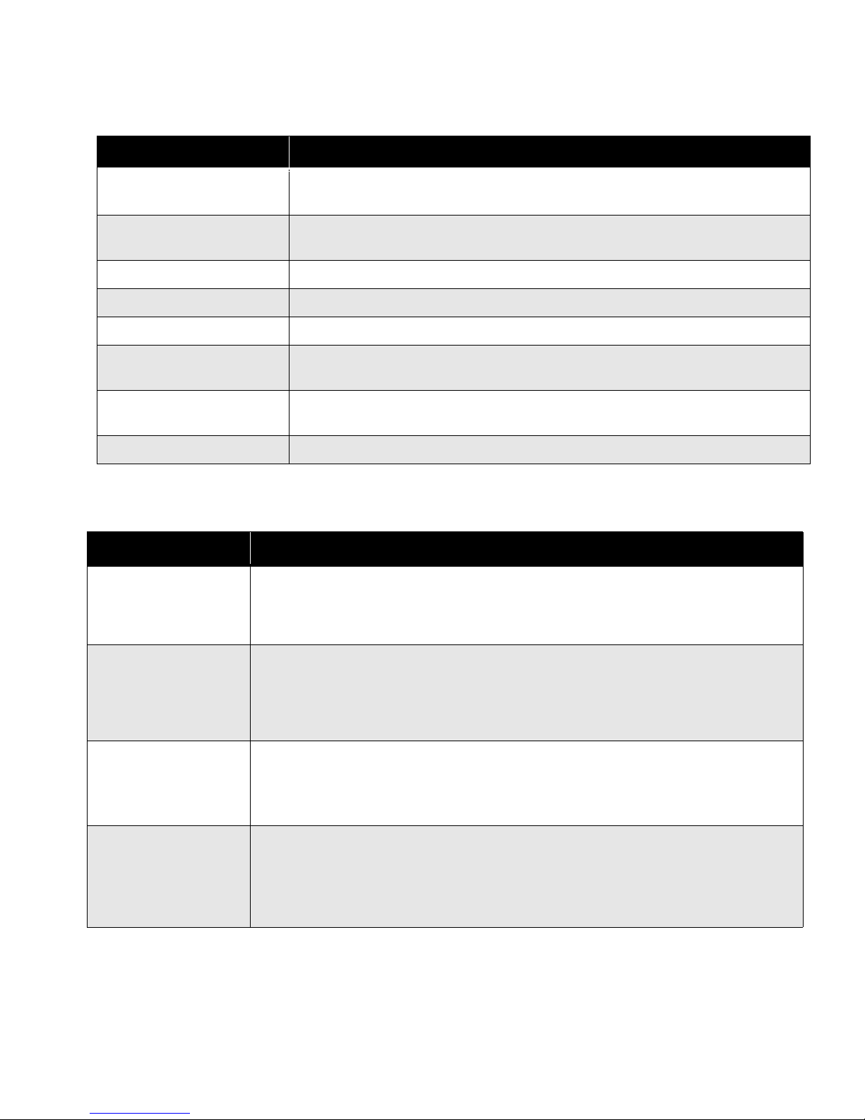
The following table lists all the LEDs located on the DTC-300A board and states the function of each LED.
Table 1: DTC-300A List of LEDs and their Functions
LEDs FUNCTION
Relay Line 1
Relay Line 2
Common Trouble Steady amber for any troubles on the DTC-300A and/or the Fire Alarm panel.
CPU Fail Steady amber for any on board CPU trouble.
Ground Fault Steady amber for any ground faults on the DTC-300A main board.
Line 1
Line 2
Power ON Green LED is ON steady when power is supplied to the board.
The following table lists the user jumpers available on the DTC-300A and their functions.
Located below Line 1 terminal block. When Line 1 relay is energized, this green
LED will illuminate steady.
Located below Line 2 terminal block. When Line 2 relay is energized, this green
LED will illuminate steady.
Telephone Line 1 status indicator LED; Red steady when the line is in use, Amber
steady when there is a line fault.
Telephone Line 2 status indicator LED; Red steady when the line is in use, Amber
steady when there is a line fault.
Table 2: DTC-300A List of Jumpers for Operation and Configuration
JUMPER NUMBER JUMPER FUNCTIONS
RESET PASSCODE: Default is normally open. TO RESET PASSCODE: Place
JW1
jumper here and power down the DTC-300A by disconnecting the 24V power source
or power down the fire alarm panel (AC and Batteries), then power back up to revert to
the default passcode. After the passcode is reset, remove the jumper.
JW2
JW3
JW4
BLOCK REMOTE CONFIGURATION: Default is normally open to BLOCK remote
configuration via modem, PC with a UIMA converter module or using the LCD and
keypad at the DTC-300A. A trouble is initiated when the jumper is ON showing that
the DTC-300A is in configuration mode. Place jumper here to ALLOW any type of
configuration. Remove jumper once configuration is complete, trouble will restore.
GROUND FAULT DETECTION: Default has jumper pins normally shorted allowing
ground fault detection on the DTC-300A. Remove this jumper to DISABLE ground
fault detection (Ground Fault LED on the DTC-300A will not operate). The Fire Alarm
Panel Ground Fault is not affected.
TROUBLE RELAY: Short pins 1 and 2 to select the TROUBLE OUTPUT relay
contacts as normally closed(N.C.) or short pins 2 and 3 to select the TROUBLE
OUTPUT relay contacts as normally open (N.O.). Default has pins 2 and 3 shorted,
check fire alarm panel for proper setting required for the TROUBLE OUTPUT
contacts.
5
Page 10
Field Wiring
Field Wiring
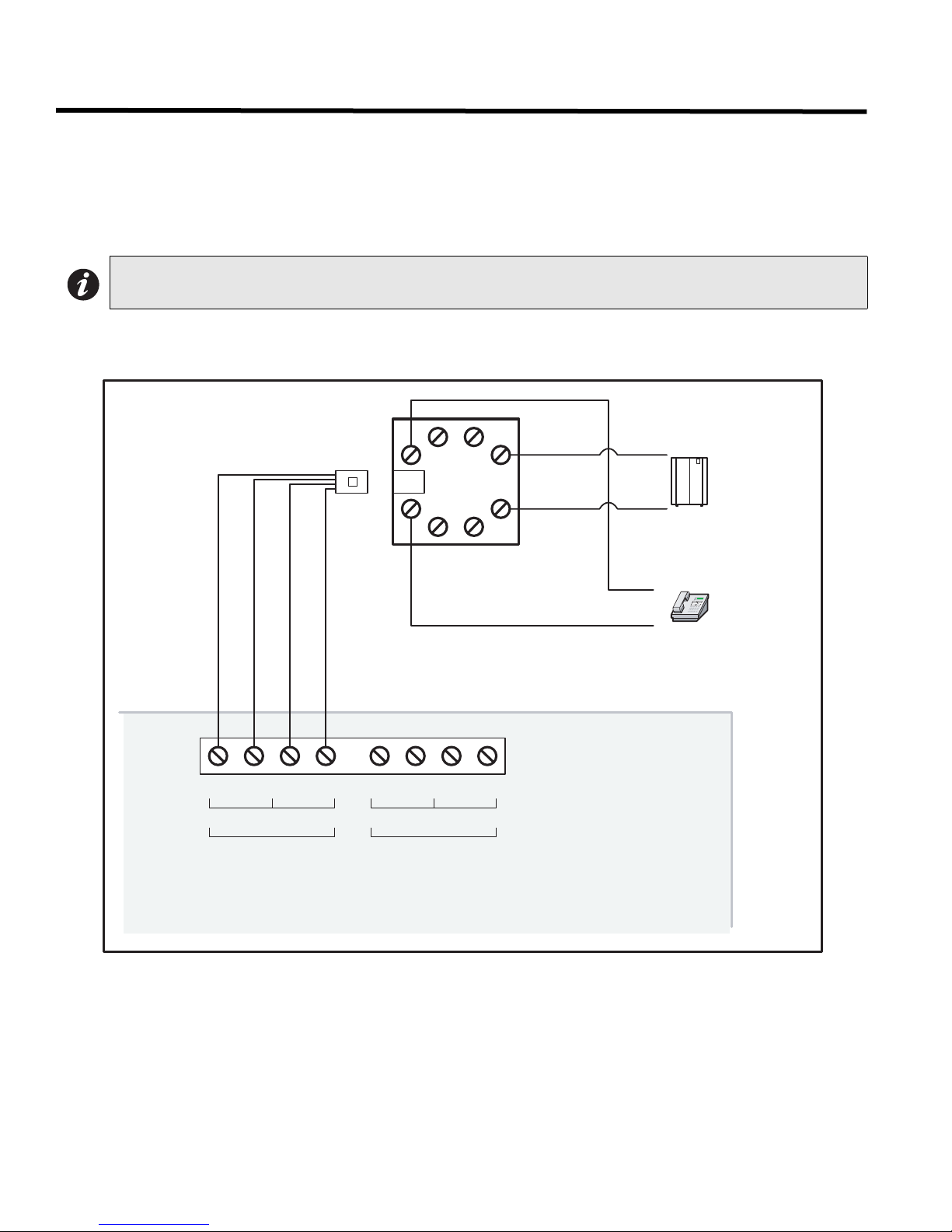
DTC-300A MAIN BOARD TELEPHONE WIRING
Wire the two telephone lines to RJ31X Connector terminals as shown in Figure 3 below. The DTC-300A telephone
line terminals are located on the top left hand corner of the board. For a cellular or wireless service, use the Line 2
interface connection.
Note: Most Authorities Having Jurisdiction (AHJ) do not allow the connection of premise
telephones. see specifications for more information.
Figure 3: Telephone Line Wiring Diagram
%52:1
7755
/LQHLV:LUHGDVVKRZQIRU/LQH
7755
5('
*5((1
*5(<
5(6 5(6&2 &2
/,1( /,1(
5-;
7,3
5,1*
3XEOLFVZLWFK
7HOHSKRQHFRPSDQ\
ZLULQJ
7,3
5,1*
SUHPLVHWHOHSKRQH
,)SHUPLWWHG
'7&$
6
Page 11

DTC-300A DACT Dialer Installation and Operation Instructions
Field Wiring (continued)
DTC-300A MAIN BOARD INPUT ZONE WIRING
There are terminals for six input zones. Zones 1 to 6 are configurable. The default zone settings are as follows:
Table 3: Zone Default Functions
ZONE DEFAULT FUNCTION
Z1 Common Alarm Input
Z2 Common Supervisory Input
Z3 Common Trouble Input
Z4 Waterflow Alarm
Z5 AC Power Trouble Input
Z6 Battery Trouble Input
Input zones 1 through 6 can be connected to the form C relay contact outputs of an associated Fire Alarm panel.
These relay outputs show the status of the Fire Alarm panel as Alarm, Supervisory, Waterflow Alarm, Common
Trouble, AC Power Fail Trouble and Battery Trouble. Each input zone is supervised by an 820 ohms End of Line
Resistor or equivalent MP-820R/W which is a resistor on a white or red plate.
Figure 4: DTC-300A Zone Wiring
7
Page 12
Field Wiring (continued)
Table 4: DTC-300A Zone Wiring Chart
Wire gauge Maximum wiring run to last device
AWG Feet Meters
22 2990 910
20 4760 1450
18 7560 2300
16 12000 3600
14 19000 5800
12 30400 9200
Notes:
• Maximum loop resistance should not exceed 100 ohms.
• Maximum capacitance of 0.5uF total on each zone.
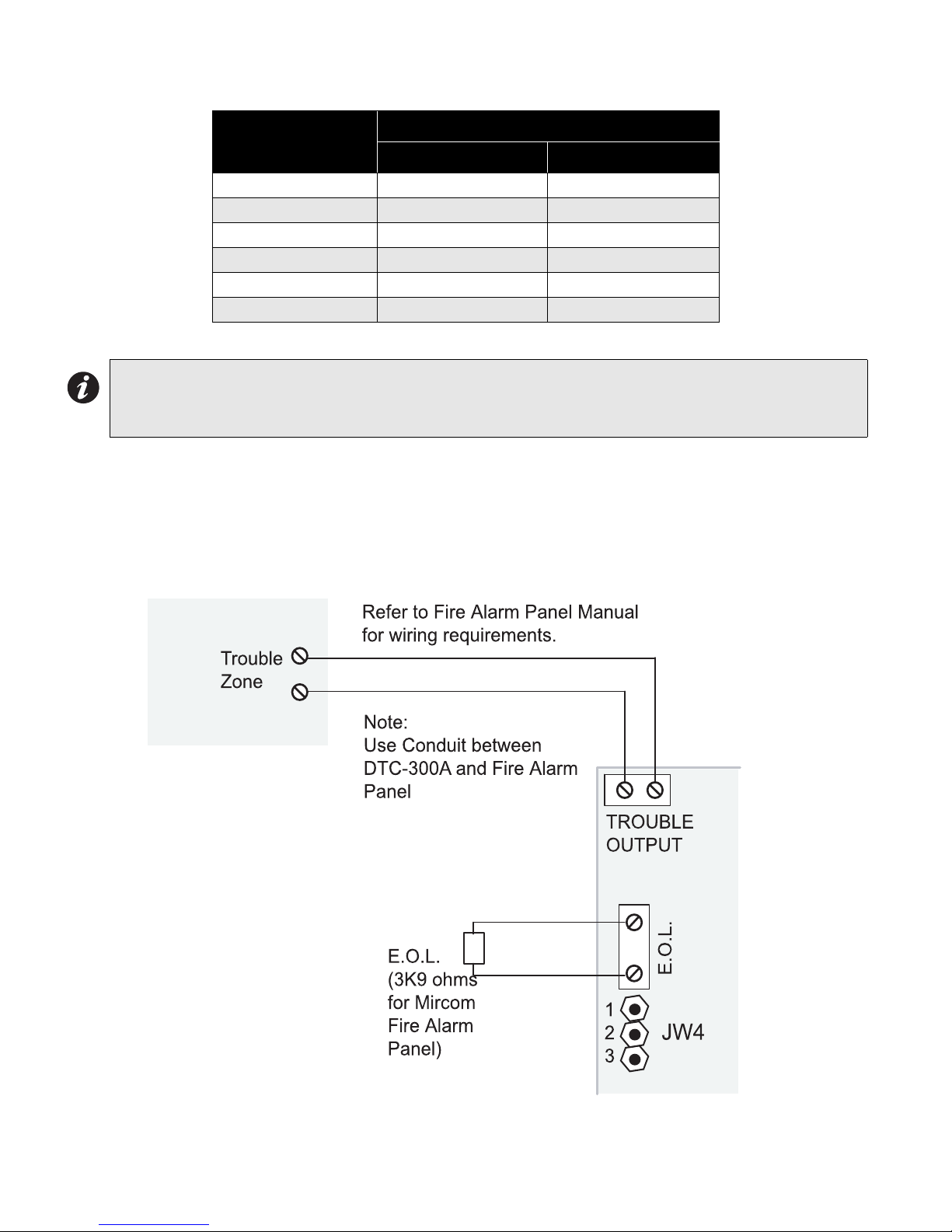
TROUBLE OUTPUT WIRING
The trouble output is wired to a Fire Alarm Trouble Only monitor zone. This is done to monitor the DTC-300A. The
E.O.L resistor required for this zone is to be placed on the terminals marked E.O.L. below the Trouble Output. The
value of the E.O.L. resistor depends on the FACP used. For the Mircom FACP, use 3K9 ohms. The Trouble Output
terminals are dry contacts. Use JW4 to select either normally closed (pins 1 and 2) or normally open (pins 2 and 3).
Figure 5: DTC-300A Trouble Output Wiring.
8
Page 13
DTC-300A DACT Dialer Installation and Operation Instructions
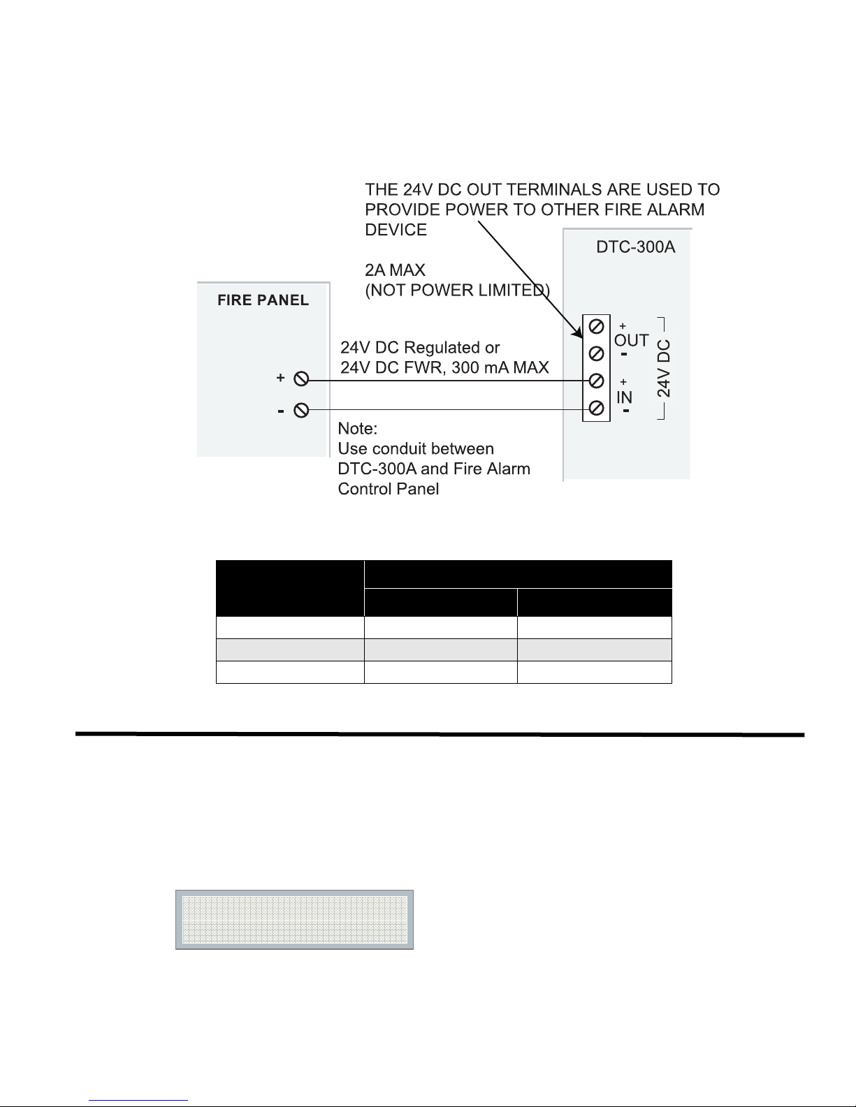
POWER SUPPLY WIRING
The DTC-300A requires power from a 24V DC regulated or 24V DC FWR supply. Connect to terminals marked 24V
DC IN, positive and negative.
Figure 6: DTC-300A 24V Power Supply Wiring
Use wire gauge for power supply wiring as specified per Table 5 below:
Table 5: Power Supply Wiring Chart
Wire gauge Maximum wiring run to last device
AWG Feet Meters
22 2530 770
20 3940 1200
18 5910 1800
Power Up Procedures
1. The DTC-300A should be securely mounted on a wall. Make sure ground wire is connected.
2. Check that the telephone lines are connected as shown in Figure 3.
3. Connect the CFG-300 Configuration Tool to the U18 connector and place over the mounting studs on the
DTC-300A above the key pad and secure. This CFG-300 Configuration Tool can be removed once
configuration has been completed.
4. Power up the Fire Alarm Panel and the message on the CFG-300 Configuration Tool should be:
S/DTC-300A Idle
00:00 SUN 2006-10-01
9
Page 14

Basic Operation and Supervision
Basic Operation and Supervision
The DTC-300A is able to supervise up to 6 local configurable input zones. Once the input zone is active (short
condition), the corresponding event with input zone number will be reported to the monitoring station. If the input
zone is open, a corresponding circuit trouble with input zone number will be reported. Each input zone can be
defined as Alarm, Supervisory, Trouble, Waterflow, AC Power Trouble or Battery Trouble.
The DTC-300A is capable of reporting multiple events to a single account number, within a single call session. For
a single event not yet reported, up to 4 retries will be made within a single call attempt. A failure to report to either
or both accounts will generate corresponding events that will be queued for reporting. Once the DTC-300A fails to
report on all telephone lines, it stops retrying, but an Alarm Event, Manual Test or 24 hour Periodic Test will force the
DTC-300A to seize the line and try reporting again. For two regular Telco telephone line connections, the DTC300A checks each line operation by reporting the 24 hour periodic test result on Line #1 or Line #2 alternately.
The DTC-300A continuously supervises the state of each of two connected Telco Lines at approximately 1 minute
intervals.The regular line supervision includes DC voltage level validation and dial tone detection. Line supervision
is skipped while (1) the dialer is busy reporting, (2) the modem is working or (3) there is ringing on the line. If the
line supervision fails, a Line #1 or Line #2 Trouble will be reported after a 30 second verification. Once the line has
been restored, a Line Trouble Restore will be reported.
Configuration Set-up
There are 3 ways of configuring the DTC-300A.
1. Locally with the on-board keypad and CFG-300 Configuration Tool.
2. Locally with a Personal Computer via the RS-232 connection, a UIMA and Mircom Software MSW-012.
3. Remotely with a computer, modem, UIMA and Mircom Software MSW-012.
CONFIGURATION VIA ON-BOARD KEYPAD
1. Connect 24V DC power supply and zone inputs from the DTC-300A to the fire alarm panel.
2. Hook up the CFG-300 Configuration Tool ribbon cable to U18 on the DTC-300A board.
3. Hook up the telephone lines and telephone as shown in Figure 3.
4. Power up the fire alarm panel and the message of the CFG-300 Configuration Tool should be:
S/DTC-300A Idle
00:00 SUN 2006-10-01
5. Place jumper on JW2, located in the bottom right hand corner of the DTC-300A board (this will generate a
trouble on the DTC-300A and report this to the receiver). Press Menu on the keypad to enter the configuration
menu and configure the DTC-300A. The following screen will ask for the passcode.
Enter Passcode
Passcode:_
6. Enter the default passcode, 1111. Press Enter.
CONFIGURATION VIA UIMA AND COMPUTER(LOCAL):
1. Set-up UIMA connection: the 10-pin cable connector of UIMA is connected to P2 on DTC-300A board. A serial
cable or USB cable is needed to connect the UIMA to the computer.
2. Place a jumper at JW2 on the DTC-300A board to allow the configuration (a trouble is generated and reported
to the receiver DACR).
10
Page 15

DTC-300A DACT Dialer Installation and Operation Instructions
3. Start the Mircom Software MSW-012 on the computer to configure the DTC-300A. Follow the instructions of
MSW-012 menu to complete the configuration of the DTC-300A.
4. Remove jumper on JW2 after configuration is finished, otherwise a trouble will occur.
CONFIGURATION VIA MODEM AND COMPUTER(REMOTE):
1. Set-up the modem connection on the computer. Make sure the phone line is working properly.
2. Place a jumper at JW2 on the DTC-300A board to allow the configuration (a trouble is generated and reported
to the receiver DACR).
3. Start the Mircom Software MSW-012 on the computer to configure the DTC-300A. Follow the instructions of
MSW-012 menu to complete the configuration of the DTC-300A.
4. Remove jumper on JW2 after configuration is finished, otherwise a trouble will occur.
11
Page 16

Keypad Configuration & Operation
Keypad Configuration & Operation
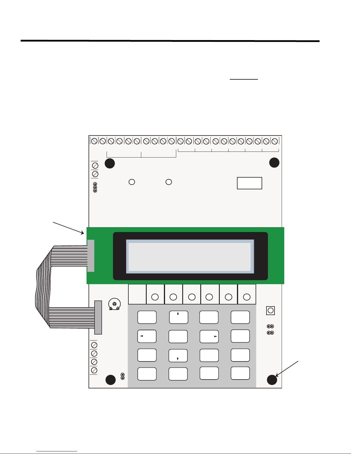
The following shows the configuration at the DTC-300A using the keypad and the CFG-300 Configuration Tool. The
Mircom Digital Communicator is configured by connecting the cable of the CFG-300 Configuration Tool to the U18
connector on the DTC-300A Main Board and placing the LCD over the 3 standoffs as shown in Figure 2.
In order to configure the DTC-300A, place a jumper on JW2, remove once configuration is complete otherwise
there will be a trouble.
To access configuration mode press the Menu button on the keypad. The CFG-300 LCD will display the Main
Menu. The keypad on the DTC-300A board and the CFG-300 is shown together in Figure 7, below.
Figure 7: DTC-300A Configuration
6<67(01250$/
021
S/DTC-300A Idle
20:00 SUN 2006-10-1
#/--/.
42/5",%
*+, -./ 012
356
#05
&!),
$%&
789
4=
'2/5.$
&!5,4
,).% ,).%
'()
:;<
0/7%2
(17(5
0(18
&$1&(/
,1)2
/.
Entering the Passcode
The programming section is passcode protected. The following image shows the message that is displayed to enter
the passcode. The minimum number of digits allowed is four and the maximum allowable passcode is ten digits
long; numerical values only. Press the “ENTER” key after entering the passcode. If the passcode is correct, it will
take you to the main command menu. If the passcode is incorrect, the system will ask you to re-enter the passcode.
The system will be exhausted after three retries and will then take you back to the Normal message display. The
default password is 1111.
After you select a feature item by pressing the "ENTER" key, use the "UP" and "DOWN" keys to move
through the different features. Use the "LEFT" and "RIGHT" keys to change the values. To confirm the
changes press the "ENTER" key. To go one level back press the "CANCEL" key.
12
Enter passcode
_
Page 17

DTC-300A DACT Dialer Installation and Operation Instructions
Command Menu
The main command menu is pictured below. The first line of the LCD will always show “-Command Menu-“, and the
second line displays the different selections. Use the “UP” and “DOWN” keys to move through the menu, and press
the “ENTER” key to make a selection. To exit from the main command menu, press “CANCEL” or select the “Exit”
menu option and then press the “ENTER” key.
Note: Command Menu feature 9 and 10 can only be accessed if jumper JW2 is placed on the main board,
see Table 1.
-Command Menu-
1. View Event Log
2. Clear Event Log
3. Test Dialer
4. Config Info
5. Version Info
6. Set Time
7. Set Password
8. Default Config
9. Dialer Config
10. Input Config
11. Exit
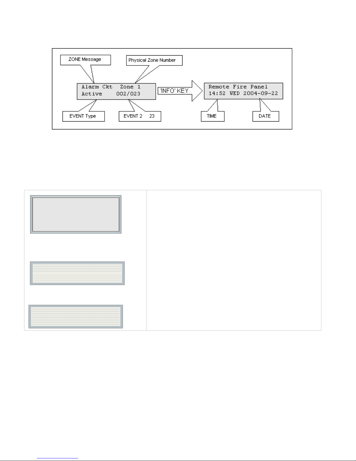
1.View Event Log (Command-Menu)
-View Event Logs1 Remote Log
2 Local Log
Select the type of log to view. Press the
“ENTER” key. The system will then show the
log chosen.
Use this function to select the log to view. Either the local or
remote log. The remote log contains all events associated
with the fire alarm panel. The local log contains all events
associated with the DTC-300A. Each log can hold up to 500
events.
13
Page 18
Keypad Configuration & Operation
Pressing the “INFO” key provides more information about the displayed event. The illustration below provides an
example of how the “INFO” key works.
of
There are a maximum of 500 recent events saved in the event log. If the number of events goes beyond 500, all
new incoming events will be ignored.
2. Clear Event Log (Command-Menu)
-Clear Log1 Remote Log
2 Local Log
3 All Logs
Select the type of log to clear. Press the
“ENTER” key. The system will then confirm
before clearing logs.
Clear all the
selected log(s)? Y
Press the “ENTER” key to confirm or the
“CANCEL” key to cancel the operation.
Log(s) cleared
Use this function to clear remote logs, local logs, or both. The
remote log contains all events associated with the fire alarm
panel. The local log contains all events associated with the
DTC-300A. Each log can hold up to 500 events.
14
Page 19

3. Test Dialer (Command-Menu)
-Dialer Test-
1. L#1 Manual test
2. L#2 Manual test
3. Reset Dialer
DTC-300A DACT Dialer Installation and Operation Instructions
1.L#1 Manual test
2.L#2 Manual test
.
3 Reset Dialer
Dialer Test Messages
The following messages will display during the test processes of Lines #1 and #2. The messages that will appear
depend on the status of the dialer and the test results that are found.
Dialer idle now
No DC Volt
Press Enter to test Line #1. Press Cancel to exit
this menu. For a description of test messages,
see Dialer Test Messages on the following
page.
Press Enter to test Line #2. Press Cancel to exit
this menu. For a description of test messages,
see Dialer Test Messages on the following
page.
This feature flushes all reportable events from
the buffer, clears all dialer troubles and resets
the dialer operation. Press Enter to reset the
dialer. Press Cancel to exit this menu.
The dialer is checking the line for voltage. This
message automatically displays when Manual Test is
selected.
No DC line voltage. The line is dead or no phone line
is connected or the phone line operates at abnormal
voltage.
Waiting for Dialtone
Failed: No Dialtone
Dialing Receiver Now
No DTMF tone
Waiting for Acktone
The dialer is waiting for a dial tone.
This message may indicate a noisy telephone line.
The dial tone was detected and telephone number
dialing is in process.
This message indicates that the dialer failed to send a
DTMF tone.
Waiting for availability of the receiver. The receiver
confirms the availability by sending an Ack tone.
15
Page 20
Keypad Configuration & Operation
Failed No Acktone
Reporting Event Now
Waiting for Kissoff
No Kissoff
Passed: Manual test
Dialer failed to detect Ack tone. This message
indicates that either the telephone number may be
wrong or the receiver is not available.
Sending events to the receiver.
The dialer is waiting for the Kissoff tone. The Kissoff
tone indicates that the receiver has received the event
reports.
No Kissoff means dialer did not detect Kissoff tone.
The line passed the test; everything is OK.
16
Page 21

4. Config Info (Command-Menu)
Configuration type:
Factory default
Press down arrow key to see more information.
DTC-300A DACT Dialer Installation and Operation Instructions
Configuration type will show how the panel was configured. “Factory
default” means the panel has not been configured, it is as it came
from the factory. “Front Panel” means it was configured at the panel.
“Serial Port” means the configuration was done from a computer
through the serial port. “Modem” means the configuration was
completed remotely through a modem.
Job Name:
No job loaded
Technician ID:
Unknown
Press down arrow key for further info
Cfg. Date and Time:
hh:mm day year:mm:dd
Press down arrow key for further info
Cfg. Tool S/W Vers.:
Version:x.x.x.x
5. Version Info
If you upload a job configuration to the panel using the PC
configuration utility, the job name will appear on this screen. The job
name can be up to a maximum of 20 characters.
If you upload a job configuration to the panel using the PC
configuration utility, the technician’s name (ID) will appear on this
screen. The technician ID can be up to a maximum of 10 characters.
Configuration date and time will appear for all means of configuration,
thus revealing date and time configuration was last changed.
This specifies the configuration tool version. It will display 0.0.0.0 if no
PC configurator has been used.
S/DTC-300A
Version 1.0.1
The first line shows the model number and panel type and the second line shows the software version number. The
version of the software is read as Major.Minor.Revision.
6. Set Time (Command-Menu)
1 Daylight Save
2 Time Clock
3 Compensation
Command Menu/Set Time
1. Daylight saving time
Daylight Saving
[X] DISABLE
[X] DISABLE ->Default
[ ] ENABLE
Use this function to enable
daylight savings time.
17
Page 22

Keypad Configuration & Operation
Command Menu/Time Clock
2. Set time and date
HH:MM WKD YYYY-MM-DD
00:00 MON 2000-01-01
Command Menu/Time Clock
3. Compensation
Daily Compensation:
0
Once the compensation value is entered the
display will be:
Daily Compensation:
Panel Config Updated
Default
00:00 MON 2000-01-01
Compensation value can
range from -15 to +15
seconds.
Use this function to set the
time and date. Use the
“LEFT” and “RIGHT” keys to
move the cursor to the
desired location in the display
and use the “UP” and
“DOWN” keys to increase or
decrease the values. Press
the “ENTER” key to accept
the changes and the
“CANCEL” key to ignore the
changes
format
. Note: time is in 24hr
Use the up down arrow keys
to select daily compensation
value and press ENTER. For
a fast clock adjust negatively.
For a slow clock adjust
positively. For example: for a
clock which runs 5 minutes a
month (based on 30 days)
fast select -10 seconds.
7. Set Password (Command-Menu)
Command Menu/Set Password
Enter new passcode
[ ]
Re-enter passcode
[ ]
If the passcode does not match, the following
message appears and the system exit to the
main menu
invalid passcode
If the passcode is OK the following message
appears and exits to the main menu
Passcode updated
1111 -> Default
Use this function to change
the passcode. The minimum
number of digits is 4 and the
maximum number is 10.
ONLY numeric digits are
allowed.
18
Page 23

DTC-300A DACT Dialer Installation and Operation Instructions
8. Default Config (Command-Menu)
Command Menu/Default Config
Load the default
settings? Y
Use this function to load the default configuration in the panel.
Press “UP” and “DOWN” to select between Y/
N. if “ENTER” is pressed the default
configuration is restored.
Warning: By loading default configuration all the previously
programmed configuration is lost permanently.
Default settings
have been loaded
9. Dialer Config (Command-Menu)
Press the Menu key on the keypad of the DTC-300A board to configure the DTC-300A. The following illustration
shows the dialer configuration menu. Each item in this menu is described below in detail. Use the Up and Down
keys to scroll through the menu and press the Enter key to make a selection. To exit from the menu, select the Exit
menu option and then press either the Enter or Cancel key. Once a menu feature has been selected, use the Left
and Right keys to change values or the numerical keys to enter account numbers.
- Dialer Config 1 Account Info
2 Telephone Line
3 Report Options
4 Time Parameter
5 Enable/Disable
6 Ring Detection
1. Account Info Menu
- Account Info -
1 Account#1 ID
2 Account#1 Tel
3 Accnt#1 Format
4 Account#2 ID
5 Account#2 Tel
6 Accnt#2 Format
19
Page 24

Keypad Configuration & Operation
Command Menu/Dialer Config/Account Info
1.Account# 1 Identification
Account#1 ID:
123456
Command Menu/Dialer Config/Account Info
2.Account#1 Telephone Number
Account#1 Telnum:
101
Command Menu/Dialer Config/Account Info
3.Account#1 Reporting Format
ACCNT#1 Format:
[X] Contact ID
123456->Default
101 ->Default
[X] CONTACT IDDefault
[ ] SIA 300 Baud
[ ] SIA 110 Baud
Use this function to set the Account ID for the
monitoring station to which the dialer reports
events. The maximum number of digits
allowed is six. For contact ID, only the first
four digits are used; the last two are truncated.
If you are using the Contact ID protocol, the
allowed digits for the account ID are simple
digits 0 to 9 and hexadecimal digits A to F. The
SIA protocol only allows digits 0 to 9.
To enter hexadecimal digits, press the INFO
button. The letter “A” will appear. To scroll
through the rest of the letters, press INFO
repeatedly. Press # key to move the cursor to
the right or press * key to move it to the left.
Use this function to set the telephone number
of the monitoring station. The maximum
number of digits allowed is 19 including
commas “,” and numerals. The commas will
be treated as 1 sec delay. To enter a comma
“,” press the INFO button. Press the # key to
move the cursor to the right or press the * key
to move it to the left. An example of a typical
telephone number is 9,,1234567008, 9 being
the dial out where required.
Set the reporting format that is
recognized or preferred by the monitoring
station.
Command Menu/Dialer Config/Account Info
4. Account# 2 Identification
Account#2 ID:
654321
Command Menu/Dialer Config/Account Info
5.Account# 2 Telephone Number
Account#2 Telnum:
101
Command Menu/Dialer Config/Account Info
6.Account# 2 Reporting Format
ACCNT#2 Format:
[X] Contact ID
654321->Default
101 ->Default
[X]
ContactID->Default
[ ] SIA 300 Baud
[ ] SIA 110 Baud
Same as Account#1.
Same as Account#1.
Same as Account#1.
20
Page 25

2. Telephone Line Menu
- Telephone Line -
1 Line1 Dialtype
2 Line2 Dialtype
3 Line1 Dialtone
4 Line2 Dialtone
5 Num of Retries
Command Menu/Dialer-Config/Telephone Line
1. Line#1 Dialing Type
Line#1 Dialing Type:
[X] DTMF Dial
Command Menu/Dialer-Config/Telephone Line
2. Line#2 Dialing Type
Line#2 Dialing Type:
[X] DTMF Dial
DTC-300A DACT Dialer Installation and Operation Instructions
[X] DTMF Dial->Def
[ ] Pulse Dial
[X] DTMF Dial->Def
[ ] Pulse Dial
Set the dialing type for line #1
DTMF is the type recognized or
preferred by the telephone
company.
Same as Line#1.
Command Menu/Dialer-Config/Telephone Line
3. Line#1 wait for Dial tone
Line#1 Wait Dialtone
[X] ENABLE
Command Menu/Dialer-Config/Telephone Line
4.Line#2 wait for Dial tone
Line#2 Wait Dialtone
[X] ENABLE
Command Menu/Dialer-Config/Telephone Line
5.Number of retries
Number of Retries:
06
[X] ENABLE ->Default
[ ] DISABLE
[X] ENABLE ->Default
[ ] DISABLE
06 ->Default
Use this function to let the system
know whether or not to wait for a
dial tone before dialing.
Same as Line#1.
Set the number of retries for both
line#1 and line#2. This function
lets the dialer retry on either line
if it is busy or not available. If the
retry count expires, the panel
reports a line trouble.
21
Page 26

Keypad Configuration & Operation
3. Report Options Menu
- Report Options -
1 Alarm Prio.
- Report Options -
2 Trouble Prio.
1 Alarm Prio.
3 Supv. Priority
2 Trouble Prio.
4 Aux Dis Report
5 Fire Panel
3 Supv. Priority
6 Operation Mode
7 Checksum Bits
CommandMenu/Dialer-Config/Report Options
1.Alarm priority
Alarm Priority:
[X] Account 1
CommandMenu/Dialer-Config/Report Options
2.Trouble priority
Trouble Priority:
[X] Account 1
CommandMenu/Dialer-Config/Report Options
3.Supervisory priority
SUPV Priority
[X] Account 1
[X] Account 1->Def
[ ] Account 2
[X] Account 1->Def
[ ] Account 2
[X] Account 1->Def
[ ] Account 2
Use this function to set
the account priority for
reporting alarms. If the
priority is set for
account#1 then the dialer
will try account#1 first for
reporting.
Use this function to set
the account priority for
reporting trouble. If the
priority is set for
account#1 then the dialer
will try account#1 first for
reporting.
Use this function to set
the account priority for
reporting supervisory
troubles. If the priority is
set for account#1 then the
dialer will try account#1
first for reporting.
4. Time Parameter Menu
-Time Parameter-
1 AC-Loss Delay
2 Cellphone Date
3 Auto-Test Time
Command Menu/Dialer-Config/Time Parameter
1.AC Loss delay
AC-Loss Delay(Hrs)
0
22
0 ->Default
Use this function to delay the
reporting of AC loss trouble on
the dialer for the programmed
time period. Selection is from 0
to 20 hours.
Page 27

Command Menu/Dialer-Config/Time Parameter
2.Cellular report date
DTC-300A DACT Dialer Installation and Operation Instructions
Cellular Report Date
0
Command Menu/Dialer-Config/Time Parameter
3.Auto test time
Auto-Test Time
00:30
5. Dialer Enable/Disable
Command Menu/Dialer-Config/Enable/Disable
Enable/Disable
[X] ENABLE
------Warning-------
Dialer Disabled!!!
0 ->Default
00:30 ->Default
[X] ENABLE ->Default
[ ] DISABLE
This function is not used, leave
default as is at 0.
Use this function to set the time
for auto test. This test has to be
performed once a day to send
the test report to the monitoring
station. The time is in 24hr
format, which means 00:30 is 30
minutes after midnight.
Please avoid the following Test
Times: 00:00, 01:55, 02:00 and
03:00
The dialer is enabled by default.
When the dialer is enabled or
disabled, a warning message
appears.
Warning: The dialer cannot
report any event to the
monitoring station if it is
disabled.
6. Ring Detection
Command Menu/Dialer-Config/Ring Detection
-Ring Detect Number-
[X]5
[ ] Disabled
[ ] 1
[ ] 2
[ ] 3
[ ] 4
[X] 5->Default
[ ] 6
[ ] 7
[ ] 8
Use this menu item to select the
number of rings on which the
panel’s modem will answer. The
default number of rings is five.
The maximum number of rings
you can define is eight.
If you select the “Disabled”
option, the modem will be
disabled and the panel will not
pick up the incoming call.
23
Page 28
Keypad Configuration & Operation
10. Input Config
-Input Zone Config-
1 Zone Type
2 Zone Label
This menu is used to program the process type and label (name) for the six input zones.
1. Zone Type
Command Menu/Input Cfg/Inp Zone Config
1. Type (Input Zone)
Zone-1 Type
[X] ALARM
6.Type (Input Zone)
Zone-6 Type
[X] Battery Trouble
2. Zone Name
Command Menu/Input Cfg/Inp Zone Type
1. Label (Input Zone)
Zone-1 Label
Zone-1
Name (Input Zone)
6.
Zone-6 Label
Zone-6
[X] ALARM ->Default
[ ] SUPV
[ ] TROUBLE
[ ] WTR-FLOW ALM
[ ] AC TROUBLE
[ ] BATTERY TROUBLE
Zone-1 ...6 ->Default
Use this function to program
the type of each input zone.
Table 2 shows the default
input types.
Use this function to set a
name or label for each input
zone.
11. Exit
Pressing “ENTER” after selecting “Exit” from the main menu will return the DTC-300A to normal operation.
24
Page 29

DTC-300A DACT Dialer Installation and Operation Instructions
ADEMCO CONTACT-ID
DTC-300A Internal Events:
Event Description Event Family Qualifier Code Group # Contact #
Phone Line #1 trouble detected Trouble New event 1 351 00 000
Phone Line #2 trouble detected Trouble New event 1 352 00 000
Phone Line #1 trouble restored Trouble Restore 3 351 00 000
Phone Line #2 trouble restored Trouble Restore 3 352 00 000
Failure to report to an Account Trouble New event 1 354 Acct # Acct #
Report to an Account successful Trouble Restore 3 354 Acct # Acct #
RS-485 Communication Trouble Trouble New event 1 350 00 485
Periodic (24 hr) Test Event (NORMAL) Test New event 1 602 00 000
Periodic (24 hr) Test Event (OFF
NORMAL)
Manually initiated dialer test Test New event 1 601 00 000
DTC-300A External Events:
Event Description Event Family Qualifier Code Group # Contact #
Test New event 1 608 00 000
Zone Fire Alarm Alarm New event 1 110 00 NNN
Zone Fire Alarm restored Alarm Restore 3 110 00 NNN
Zone Trouble detected Trouble New event 1 300 00 NNN
Zone Trouble restored Trouble Restore 3 300 00 NNN
Zone Supervisory condition Supervisory New event 1 200 00 NNN
Zone Supervisory restored Supervisory Restore 3 200 00 NNN
Waterflow Alarm New event 1 113 00 NNN
Waterflow restored Alarm Restore 3 113 00 NNN
Indicating Zone Trouble Trouble New event 1 320 00 NNN
Indicating Zone Trouble restored Trouble Restore 3 320 00 NNN
General Alarm Alarm New event 1 140 00 NNN
General Alarm restored Alarm Restore 3 140 00 NNN
AC power lost Trouble New event 1 301 00 000
AC power restored Trouble Restore 3 301 00 000
Battery Low Trouble New event 1 302 00 000
Battery Low restored Trouble Restore 3 302 00 000
Ground Fault Trouble New event 1 310 00 000
Ground Fault restored Trouble Restore 3 310 00 000
NNN-Refers to Sensor number for zone causing event.
25
Page 30

Keypad Configuration & Operation
SECURITY INDUSTRIES ASSOC. SIA-DCS
DTC-300A Internal Events:
Event Description Event Family Qualifier SIA Event Code Parameter
Phone Line #1 trouble detected Trouble New event LT 001
Phone Line #2 trouble detected Trouble New event LT 002
Phone Line #1 trouble restored Trouble Restore LR 001
Phone Line #2 trouble restored Trouble Restore LR 002
Failure to report to an Account Trouble New event RT Acct #
Report to an Account successful Trouble Restore YK Acct #
RS485 Communication Trouble Trouble New event YS 485
Periodic (24 hr) Test Event (Normal) Test New event RP 000
Periodic (24 hr) Test Event (Off-normal) Test New event RY 000
Manually initiated dialer test Test New event RX 000
DTC-300A External Events:
Event Description Event Family Qualifier SIA Event Code Parameter
Zone Fire Alarm Alarm New event FA NNN
Zone Fire Alarm restored Alarm Restore FH NNN
Zone Trouble detected Trouble New event FT NNN
Zone Trouble restored Trouble Restore FJ NNN
Zone Supervisory condition Supervisory New event FS NNN
Zone Supervisory restored Supervisory Restore FR NNN
Waterflow alarm Alarm New event WA NNN
Waterflow alarm restored Alarm Restore WH NNN
General Alarm Alarm New event QA NNN
General Alarm restored Alarm Restore QH NNN
Indicating Zone Trouble (*) Trouble New event UT NNN
Indicating Zone Trouble restored (*) Trouble Restore UR NNN
AC power lost Trouble New event AT 000
AC power restored Trouble Restore AR 000
Battery Low Trouble New event YT 000
Battery Low restored Trouble Restore YR 000
Ground Fault Trouble New event YP 000
Ground Fault restored Trouble Restore YQ 000
* SIA protocol does not define indicating zone troubles, but lists it as Untyped Zone Trouble/Restore.
26
Page 31

DTC-300A DACT Dialer Installation and Operation Instructions
Compatible Fire Alarm Control Panels
Mircom DTC-300A: Compatible with Mircom FA-300 Series, FX-2000 Series and FA-1000 Series Fire Alarm
Control Panels and all other FACP that can provide 24V DC regulated or 24V DC FWR power,
60mA current MIN and 110mA MAX and normally open relay contacts rated 28V DC, 2A
resistive load.
Compatible Receivers
The Mircom DTC-300A is compatible with the following Digital Alarm Communicator Receivers (DACR) ...
DACR Receiver Model
SurGard MLR2 Multi-Line Receiver (ULC, ULI Approved) SIA-DCS and Ademco Contact ID
SurGard SLR Single-Line Receiver (ULC, ULI Approved) SIA-DCS and Ademco Contact ID
Osborne-Hoffman Quickalert! II Receiver (ULI Approved) SIA-DCS and Ademco Contact ID
Osborne-Hoffman OH-2000 Receiver (ULI Approved) SIA-DCS and Ademco Contact ID
Silent Knight Model 9500 Receiver (ULI Approved) SIA-DCS and Ademco Contact ID
Radionics Model D6500 Receiver (ULI Approved) Ademco Contact ID
Radionics Model D6600 Receiver (ULI Approved) SIA-DCS and Ademco Contact ID
Protocols
27
Page 32

Specifications
Specifications
All Circuits are Power Limited except 24V DC OUT
DTC-300A Digital Communicator
• Connects to two Telephone Lines and performs line supervision.
• Connects to a FACP via input zones and 24V DC regulated or 24V DC FWR power.
• Transmits user configurable Alarm, Supervisory, and Trouble status to a DACR, using either Ademco Contact
ID or SIA DCS protocols.
• User configurable locally or remotely. Configuration is passcode protected.
• Current Consumption: Standby: 60 mA Alarm: 110 mA
Battery Calculations
DTC-300A
The DTC-300A Battery Calculations are performed as part of the calculations for the Fire Alarm Control Panel it will
be used in. See the appropriate Mircom Installation and Operation Manual.
28
Page 33

DTC-300A DACT Dialer Installation and Operation Instructions
Warranty & Warning Information
Warning Please Read Carefully
Note to End Users: This equipment is subject to terms and conditions of sale as follows:
Note to Installers
This warning contains vital information. As the only individual in contact with system users, it is your responsibility to
bring each item in this warning to the attention of the users of this system. Failure to properly inform system endusers of the circumstances in which the system might fail may result in over-reliance upon the system. As a result,
it is imperative that you properly inform each customer for whom you install the system of the possible forms of
failure.
System Failures
This system has been carefully designed to be as effective as possible. There are circumstances, such as fire or
other types of emergencies where it may not provide protection. Alarm systems of any type may be compromised
deliberately or may fail to operate as expected for a variety of reasons. Some reasons for system failure include:
•Inadequate Installation
A Fire Alarm system must be installed in accordance with all the applicable codes and standards in order to provide
adequate protection. An inspection and approval of the initial installation, or, after any changes to the system, must
be conducted by the Local Authority Having Jurisdiction. Such inspections ensure installation has been carried out
properly.
•Power Failure
Control units, smoke detectors and many other connected devices require an adequate power supply for proper
operation. If the system or any device connected to the system operates from batteries, it is possible for the
batteries to fail. Even if the batteries have not failed, they must be fully charged, in good condition and installed
correctly. If a device operates only by AC power, any interruption, however brief, will render that device inoperative
while it does not have power. Power interruptions of any length are often accompanied by voltage fluctuations which
may damage electronic equipment such as a fire alarm system. After a power interruption has occurred,
immediately conduct a complete system test to ensure that the system operates as intended.
•Failure of Replaceable Batteries
Systems with wireless transmitters have been designed to provide several years of battery life under normal
conditions. The expected battery life is a function of the device environment, usage and type. Ambient conditions
such as high humidity, high or low temperatures, or large temperature fluctuations may reduce the expected battery
life. While each transmitting device has a low battery monitor which identifies when the batteries need to be
replaced, this monitor may fail to operate as expected. Regular testing and maintenance will keep the system in
good operating condition.
•Compromise of Radio Frequency (Wireless) Devices
Signals may not reach the receiver under all circumstances which could include metal objects placed on or near the
radio path or deliberate jamming or other inadvertent radio signal interference.
•System Users
A user may not be able to operate a panic or emergency switch possibly due to permanent or temporary physical
disability, inability to reach the device in time, or unfamiliarity with the correct operation. It is important that all
system users be trained in the correct operation of the alarm system and that they know how to respond when the
system indicates an alarm.
•Automatic Alarm Initiating Devices
Smoke detectors, heat detectors and other alarm initiating devices that are a part of this system may not properly
detect a fire condition or signal the control panel to alert occupants of a fire condition for a number of reasons, such
as: the smoke detectors or heat detector may have been improperly installed or positioned; smoke or heat may not
29
Page 34

Warranty & Warning Information
be able to reach the alarm initiating device, such as when the fire is in a chimney, walls or roofs, or on the other side
of closed doors; and, smoke and heat detectors may not detect smoke or heat from fires on another level of the
residence or building.
•Software
Most Mircom products contain software. With respect to those products, Mircom does not warranty that the
operation of the software will be uninterrupted or error-free or that the software will meet any other standard of
performance, or that the functions or performance of the software will meet the user’s requirements. Mircom shall
not be liable for any delays, breakdowns, interruptions, loss, destruction, alteration or other problems in the use of a
product arising our of, or caused by, the software.
Every fire is different in the amount and rate at which smoke and heat are generated. Smoke detectors cannot
sense all types of fires equally well. Smoke detectors may not provide timely warning of fires caused by
carelessness or safety hazards such as smoking in bed, violent explosions, escaping gas, improper storage of
flammable materials, overloaded electrical circuits, children playing with matches or arson.
Even if the smoke detector or heat detector operates as intended, there may be circumstances when there is
insufficient warning to allow all occupants to escape in time to avoid injury or death.
•Alarm Notification Appliances
Alarm Notification Appliances such as sirens, bells, horns, or strobes may not warn people or waken someone
sleeping if there is an intervening wall or door. If notification appliances are located on a different level of the
residence or premise, then it is less likely that the occupants will be alerted or awakened. Audible notification
appliances may be interfered with by other noise sources such as stereos, radios, televisions, air conditioners or
other appliances, or passing traffic. Audible notification appliances, however loud, may not be heard by a hearingimpaired person.
•Telephone Lines
If telephone lines are used to transmit alarms, they may be out of service or busy for certain periods of time. Also
the telephone lines may be compromised by such things as criminal tampering, local construction, storms or
earthquakes.
•Insufficient Time
There may be circumstances when the system will operate as intended, yet the occupants will not be protected from
the emergency due to their inability to respond to the warnings in a timely manner. If the system is monitored, the
response may not occur in time enough to protect the occupants or their belongings.
•Component Failure
Although every effort has been made to make this system as reliable as possible, the system may fail to function as
intended due to the failure of a component.
•Inadequate Testing
Most problems that would prevent an alarm system from operating as intended can be discovered by regular testing
and maintenance. The complete system should be tested as required by national standards and the Local Authority
Having Jurisdiction and immediately after a fire, storm, earthquake, accident, or any kind of construction activity
inside or outside the premises. The testing should include all sensing devices, keypads, consoles, alarm indicating
devices and any other operational devices that are part of the system.
•Security and Insurance
Regardless of its capabilities, an alarm system is not a substitute for property or life insurance. An alarm system
also is not a substitute for property owners, renters, or other occupants to act prudently to prevent or minimize the
harmful effects of an emergency situation.
IMPORTANT NOTE: End-users of the system must take care to ensure that the system, batteries, telephone lines,
etc. are tested and examined on a regular basis to ensure the minimization of system failure.
30
Page 35

DTC-300A DACT Dialer Installation and Operation Instructions
Limited Warranty
Mircom Technologies Ltd. warrants the original purchaser that for a period of two years from the date of
manufacture, the product shall be free of defects in materials and workmanship under normal use. During the
warranty period, Mircom Technologies Ltd. shall, at its option, repair or replace any defective product upon return of
the product to its factory, at no charge for labor and materials. Any replacement and/or repaired parts are warranted
for the remainder of the original warranty or ninety (90) days, whichever is longer. The original owner must promptly
notify Mircom Technologies Ltd. in writing that there is defect in material or workmanship, such written notice to be
received in all events prior to expiration of the warranty period.
International Warranty
The warranty for international customers is the same as for any customer within Canada and the United States, with
the exception that Mircom Technologies Ltd. shall not be responsible for any customs fees, taxes, or VAT that may
be due.
Conditions to Void Warranty
This warranty applies only to defects in parts and workmanship relating to normal use. It does not cover:
•damage incurred in shipping or handling;
•damage caused by disaster such as fire, flood, wind, earthquake or lightning;
•damage due to causes beyond the control of Mircom Technologies Ltd. such as excessive voltage, mechanical
shock or
•water damage;
•damage caused by unauthorized attachment, alterations, modifications or foreign objects;
•damage caused by peripherals (unless such peripherals were supplied by Mircom Technologies Ltd.);
•defects caused by failure to provide a suitable installation environment for the products;
•damage caused by use of the products for purposes other than those for which it was designed;
•damage from improper maintenance;
•damage arising out of any other abuse, mishandling or improper application of the products.
Warranty Procedure
To obtain service under this warranty, please return the item(s) in question to the point of purchase. All authorized
distributors and dealers have a warranty program. Anyone returning goods to Mircom Technologies Ltd. must first
obtain an authorization number. Mircom Technologies Ltd. will not accept any shipment whatsoever for which prior
authorization has not been obtained. NOTE: Unless specific pre-authorization in writing is obtained from Mircom
management, no credits will be issued for custom fabricated products or parts or for complete fire alarm system.
Mircom will at its sole option, repair or replace parts under warranty. Advance replacements for such items must be
purchased.
Note: Mircom Technologies Ltd.’s liability for failure to repair the product under this warranty after a reasonable
number of attempts will be limited to a replacement of the product, as the exclusive remedy for breach of warranty.
Disclaimer of Warranties
This warranty contains the entire warranty and shall be in lieu of any and all other warranties, whether expressed or
implied (including all implied warranties of merchantability or fitness for a particular purpose) And of all other
obligations or liabilities on the part of Mircom Technologies Ltd. neither assumes nor authorizes any other person
purporting to act on its behalf to modify or to change this warranty, nor to assume for it any other warranty or liability
concerning this product.
This disclaimer of warranties and limited warranty are governed by the laws of the province of Ontario, Canada.
31
Page 36

Warranty & Warning Information
Out of Warranty Repairs
Mircom Technologies Ltd. will at its option repair or replace out-of-warranty products which are returned to its
factory according to the following conditions. Anyone returning goods to Mircom Technologies Ltd. must first obtain
an authorization number. Mircom Technologies Ltd. will not accept any shipment whatsoever for which prior
authorization has not been obtained.
Products which Mircom Technologies Ltd. determines to be repairable will be repaired and returned. A set fee which
Mircom Technologies Ltd. has predetermined and which may be revised from time to time, will be charged for each
unit repaired.
Products which Mircom Technologies Ltd. determines not to be repairable will be replaced by the nearest equivalent
product available at that time. The current market price of the replacement product will be charged for each
replacement unit.
WARNING: Mircom Technologies Ltd. recommends that the entire system be completely tested on a regular
basis. However, despite frequent testing, and due to, but not limited to, criminal tampering or electrical
disruption, it is possible for this product to fail to perform as expected.
NOTE: Under no circumstances shall Mircom Technologies Ltd. be liable for any special, incidental, or
consequential damages based upon breach of warranty, breach of contract, negligence, strict liability, or
any other legal theory. Such damages include, but are not limited to, loss of profits, loss of the product or
any associated equipment, cost of capital, cost of substitute or replacement equipment, facilities or
services, down time, purchaser’s time, the claims of third parties, including customers, and injury to
property.
MIRCOM MAKES NO WARRANTY OF MERCHANTABILITY OR FITNESS FOR A PARTICULAR PURPOSE
WITH RESPECT TO ITS GOODS DELIVERED, NOR IS THERE ANY OTHER WARRANTY, EXPRESSED OR
IMPLIED, EXCEPT FOR THE WARRANTY CONTAINED HEREIN.
32
Page 37

DTC-300A DACT Dialer Installation and Operation Instructions
DTC-300A INFORMATION FORM
Account #1 Identification (max. 6 digits): _ _ _ _ _ _
Account #1 Telephone number (including area code): __________________________
Telephone number of receiving station (including area code) : ____________________
Reporting Format: Contact ID
SIA
_________________________________________________________________________________________
Account #2 Identification (max. 6 digits): _ _ _ _ _ _
Account #2 Telephone number (including area code): __________________________
Telephone number of receiving station (including area code): ____________________
Reporting Format: Contact
SIA
33
Page 38

Notes
Page 39

Page 40

Canada
25 Interchange Way
Vaughan, ON L4K 5W3
Tel: 905-660-4655 Fax: 905-660-4113
© Mircom 2006
Printed in Canada
Subject to change without prior notice
www.mircom.com
Advanced Life Safety Solutions
U.S.A.
60 Indust
rial Parkway PMB 278
Cheektowaga, NY 14227
Tel: 1-888-660-4655 Fax: 1-888-660-4113
 Loading...