

Page 1
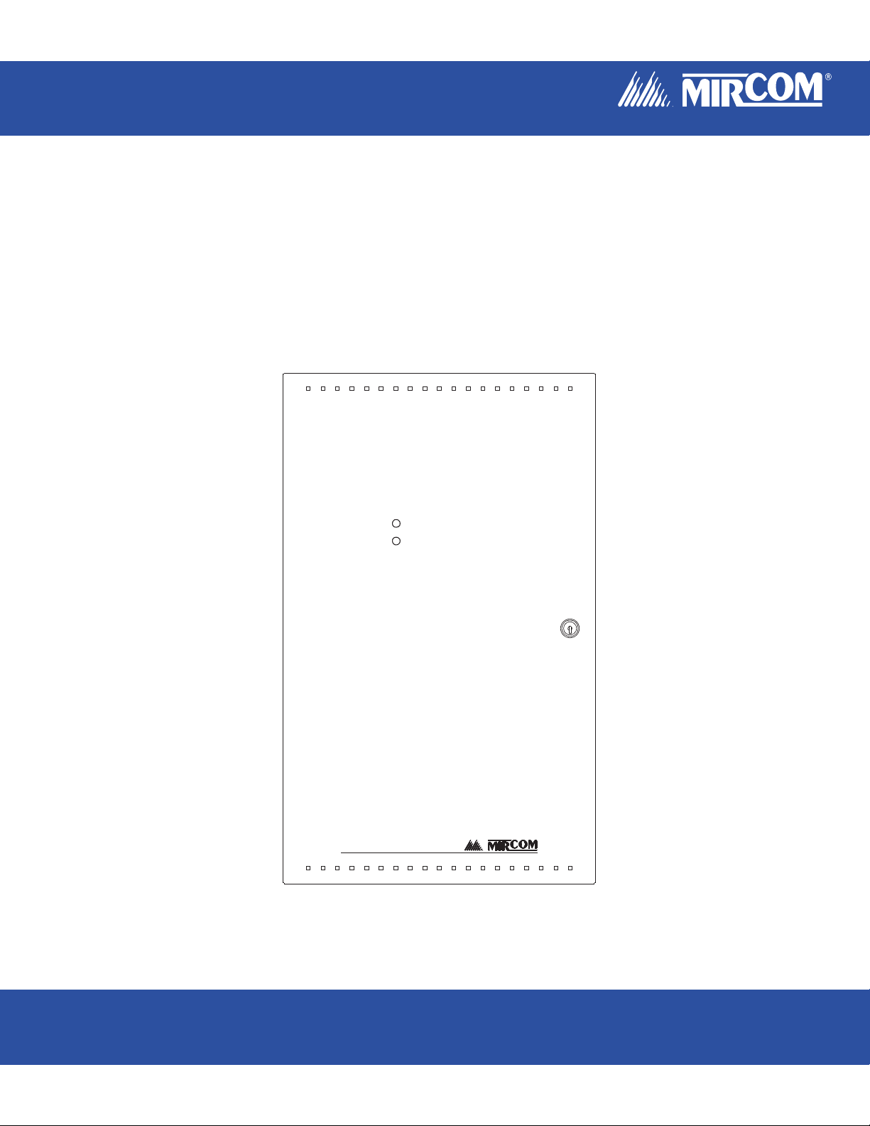
BPS-1100
Signal Booster Power Supply
BPS-1100
SIGNAL BOOSTER POWER SUPPLY
Installation and Operation Manual
LT-913 Rev. 4
May 2008
Page 2

Page 3

BPS-1100 Installation and Operation Manual
Table of Contents
1.0 Introduction ........................................................................................................................ 1
1.1 Overall Features: ............................................................................................................ 1
1.2 Controls and Indicators ................................................................................................... 1
2.0 General Notes..................................................................................................................... 2
3.0 System Components ........................................................................................................ 3
3.1 Chassis Type .................................................................................................................. 4
3.2 BPS-1100 Accessories ................................................................................................... 4
4.0 Mechanical Installation and Dimensions ......................................................................... 5
4.1 Main Chassis Installation ................................................................................................ 6
5.0 Modules Mounting Locations ........................................................................................... 7
6.0 Module Settings ................................................................................................................. 9
6.1 Main Chassis Board of the BPS-1100 ............................................................................ 9
6.2 Main Display Module (Part of Main Chassis) .................................................................. 10
6.3 Signal Adder Module (Model SGM-1004A)..................................................................... 11
6.4 Relay Adder Module (Model RM-1008A) ........................................................................ 12
7.0 Field Wiring......................................................................................................................... 13
7.1 Main Board Terminal Connections.................................................................................. 13
7.2 Signal Adder Module (SGM-1004A) Terminal Connections ........................................... 15
7.3 Relay Adder Module (RM-1008A) Terminal Connections............................................... 16
7.4 Power Supply Connections............................................................................................. 17
7.5 Wiring Tables & Information............................................................................................ 18
8.0 System Checkout ............................................................................................................... 19
8.1 Before Turning The Power "ON"..................................................................................... 19
8.2 Power-up Procedure ....................................................................................................... 19
8.3 Troubleshooting .............................................................................................................. 19
9.0 Indicators, Controls, & Operation..................................................................................... 20
9.1 Common Indicators......................................................................................................... 21
9.2 Common Controls ........................................................................................................... 21
9.3 Circuit Status Indicators .................................................................................................. 22
9.4 Circuit (Zone) Disconnect Switches ................................................................................ 22
9.5 Circuit Types ................................................................................................................... 23
10.0 System Configuration...................................................................................................... 24
10.1 Introduction To Configuration........................................................................................ 24
10.2 Entering Configuration Mode ........................................................................................ 25
10.3 Exiting Configuration Mode........................................................................................... 25
10.4 Factory Default Configuration ....................................................................................... 26
10.5 Restore To Default / Resize.......................................................................................... 26
10.6 Resize System (Set Adder Module Number & Type).................................................... 26
10.7 Configuring Features .................................................................................................... 27
10.8 Configuring Indicating Circuits: ..................................................................................... 28
10.9 Configuring Circuit Correlations: ................................................................................... 29
10.10 Display Configuration.................................................................................................. 29
Appendix A - Module Specifications And Features .............................................................. 30
Compliance ........................................................................................................................... 30
Appendix B - Power Supply & Battery Calculations (Selection Guide) .............................. 31
Warranty & Warning Information............................................................................................ 32
Warning Please Read Carefully............................................................................................ 32
Limited Warranty................................................................................................................... 34
Warranty Procedure.............................................................................................................. 34
Disclaimer of Warranties.......................................................................................................
Out of Warranty Repairs ....................................................................................................... 35
34
i
Page 4

Page 5

List of Figures and Headings
Figure 1: BPS-1100 Flush or Surface Enclosure Installation and Dimensions ....................5
Figure 2: Main Chassis Installation ......................................................................................6
Figure 3: Module Mounting Locations ..................................................................................7
Figure 4: Adder Module Mounting Details ............................................................................8
Figure 5: Main Chassis board of the BPS-1100 ...................................................................9
Figure 6: Main Display Module (For Service Personnel) .....................................................10
Figure 7: Signal Adder Module ............................................................................................11
Figure 8: Relay Adder Module .............................................................................................12
Figure 9: Main BPS-1100 Module Terminal Connections ....................................................13
Figure 10: Main BPS-1100 Module Terminal Connections (continued) ...............................14
Figure 11: Signal Module Terminal Connections .................................................................15
Figure 12: Relay Adder Module Terminal Connections .......................................................16
Figure 13: Power Supply Connections .................................................................................17
Figure 14: Indicators and Control Location ..........................................................................20
Figure 15: Evacuation Codes ...............................................................................................23
Figure 16: Configuration Indicators and Controls ................................................................24
Table 1: Wiring Table for Input Circuits ................................................................................18
Table 2: Wiring Table for Indicating Circuits ........................................................................18
Table 3: Configuration Dip Switch Function Table ...............................................................25
Table 4: Feature Configuration Dip Switch Table ................................................................27
BPS-1100 Installation and Operation Manual
iii
Page 6

Page 7
BPS-1100 Installation and Operation Manual
1.0 Introduction
Mircom's BPS-1100 Signal Booster Power Supply provides up to 20 fully supervised Class A or B (UL Style Z or Y)
Indicating Circuits. All Indicating Circuits are fully supervised for opens, shorts and grounds. Optional Adder
Modules include additional Indicating Circuits and Relay Circuits. Flush or surface mountable enclosures can be
used for retrofits and on new installations.
1.1 Overall Features:
• 120V/240V AC, 24V DC, 11 Amps Max
• Basic unit has 4 Power Limited Class A/B (Style Z/Y) Indicating Circuits with individual trouble indicators (1.7A
Max per circuit).
• 4 supervised programmable inputs
• Optional 3 Adder Modules for additional Indicating and Relay Circuits. Indicating Circuits expandable by 16
(with 3 SGM-1004As) and Relay Circuits by 16 (with 2 RM-1008As).
• Supports supervised and unsupervised suite isolators
• Regulated Auxiliary Output 24V DC, 1.7A
• Space for 10 to 17 Amp Hour Batteries
• Each Indicator Circuit can be configured as Audible or Visual. Audibles may be steady, Temporal Code,
California Code, or March Time.
• Indicating Circuits may be individually Disconnected by a DIP Switch.
• Two outputs (200 mA each Max., 300 mA total Max.)
• Auxiliary Relay Contacts for Common Ground and Common Trouble.
• Easy Configuration via Pushbuttons and Switches.
• Extensive transient protection
• Surface Mountable Enclosures, Flush Trims Available
1.2 Controls and Indicators
4 Pushbuttons, 7 Common Indicators, provision for up to 4 Inputs and 20 Output Points.
1
Page 8

2.0 General Notes
2.0 General Notes
Number Of Adders That May Be Installed
The maximum number of Adder Modules that may be physically installed in a BPS-1100 is 3 Adder Modules, a
combination of the following:
SGM-1004A Signal Adder Module (maximum of 16 Indicating Circuits in a system)
RM-1008A Relay Adder Module (maximum of 16 Relay Circuits in a system)
Circuits And Zones
Circuits refers to an actual electrical interface, Input (Detection), Indicating (Signal), or Relay.
Display Points
On the BPS-1100 an important concept is Display Points. Unlike some products the available LED Displays and
matching Circuit Disconnect Switches are not hard-wired to the Circuit Adder Modules. The Main Chassis provides
a fixed number of Display Points on their attached Display Boards. These are assigned during the Configuration
Adder Module Number and Type operation (see Configuration Section) as required in the cabling order in which
Adder Modules are installed. In any system setup, there must be at least as many Display Points available, as those
required by the Circuits.
Wiring Styles
Input Circuits are configured as Class B (Style B).
Indicating (Output) Circuits may be individually wired as Class A (Style Z) or Class B (Style Y) without affecting the
number of circuits available (see Field Wiring instructions).
2
Page 9
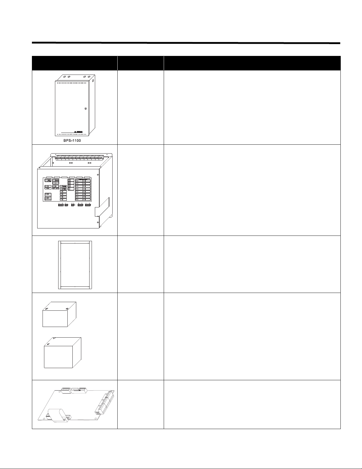
3.0 System Components
W= 5.94"
H= 3.94"
D= 3.86"
W= 7.13"
H= 6.58"
D= 2.29"
SA12120
10AH
SA12180
17AH
Model Description
BB-1024 Surface Enclosure
BPS-1100
SIGNAL BOOSTER POWER SUPPLY
INPUT 1
OUTPUT 13
OUTPUT 5
INPUT 2
OUTPUT 14
OUTPUT 6
INPUT 3
OUTPUT 7
OUTPUT 15
INPUT 4
OUTPUT 16
OUTPUT 8
OUTPUT 9
OUTPUT 1
OUTPUT 1
OUTPUT 2
SELECT
OUTPUT 3
OUTPUT 4
CONFIRM
CONFIG.
O/P ZONE
DISCONNECT
OUTPUT 17
OUTPUT 10
OUTPUT 18
OUTPUT 11
OUTPUT 19
OUTPUT 12
OUTPUT 20
I/P ZONE
O/P ZONE
O/P ZONE
DISCONNECT
DISCONNECT
DISCONNECT
MCC-1100-12 12 A Main Chassis
BPS-1100 Installation and Operation Manual
FA-1024TR Flush Trim Ring (add another suffix R for Red Enclosure)
12 VOLT
Batteries (10
to 17AH)
(2 required for
Use Sota Enertech batteries models: SA12120 (Mircom
#BA-110) and SA-12180 (Mircom #BA-117).
24 volts)
SGM-1004A
Circuit Adder Modules
RM-1008A
3
Page 10

3.0 System Components
3.1 Chassis Type
MCC-1100-12
Main Chassis with 4 Style Y or Z Indicating
Circuits, and a 12 ampere Power Supply. See Module Specifications Appendix A - Module Specifications And
Features on page 30 for more details.
3.2 BPS-1100 Accessories
MP-300 EOL Resistor Plate
MP-300R EOL Resistor Plate, Red
MP-300S EOL Resistor Plate, Stainless steel finish
4
Page 11
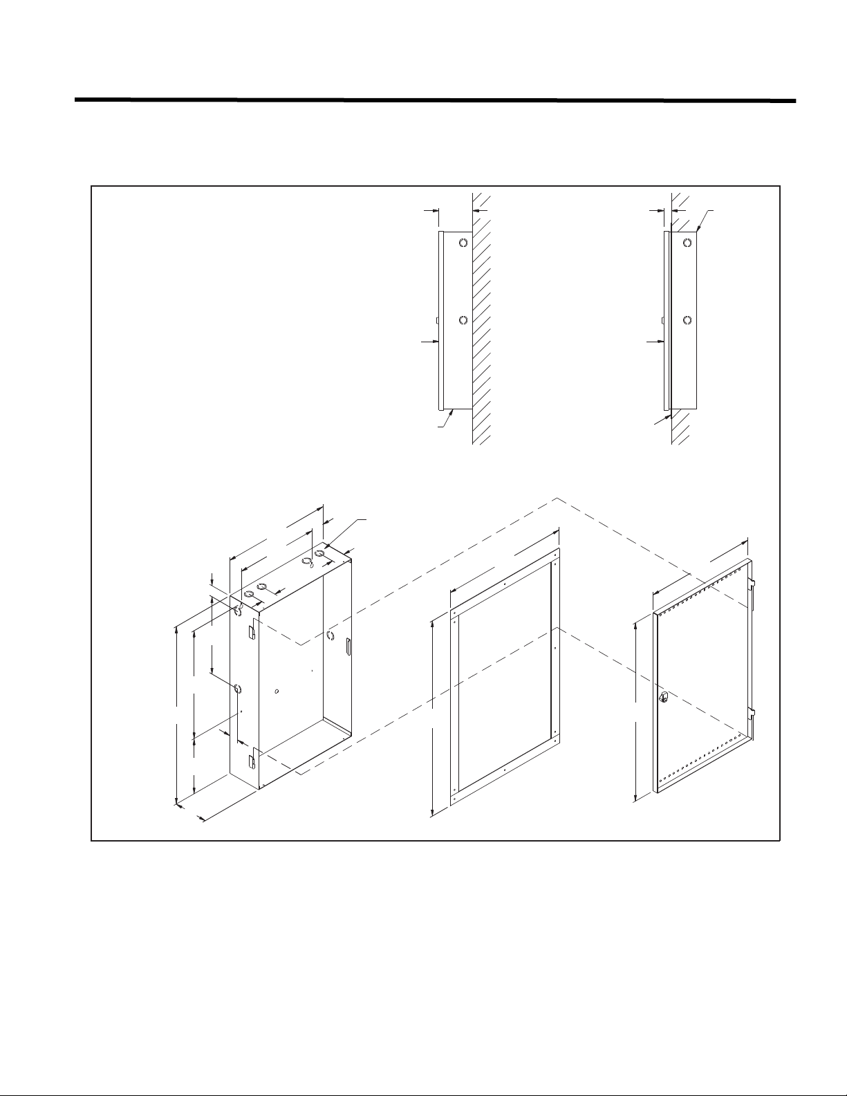
4.0 Mechanical Installation and Dimensions
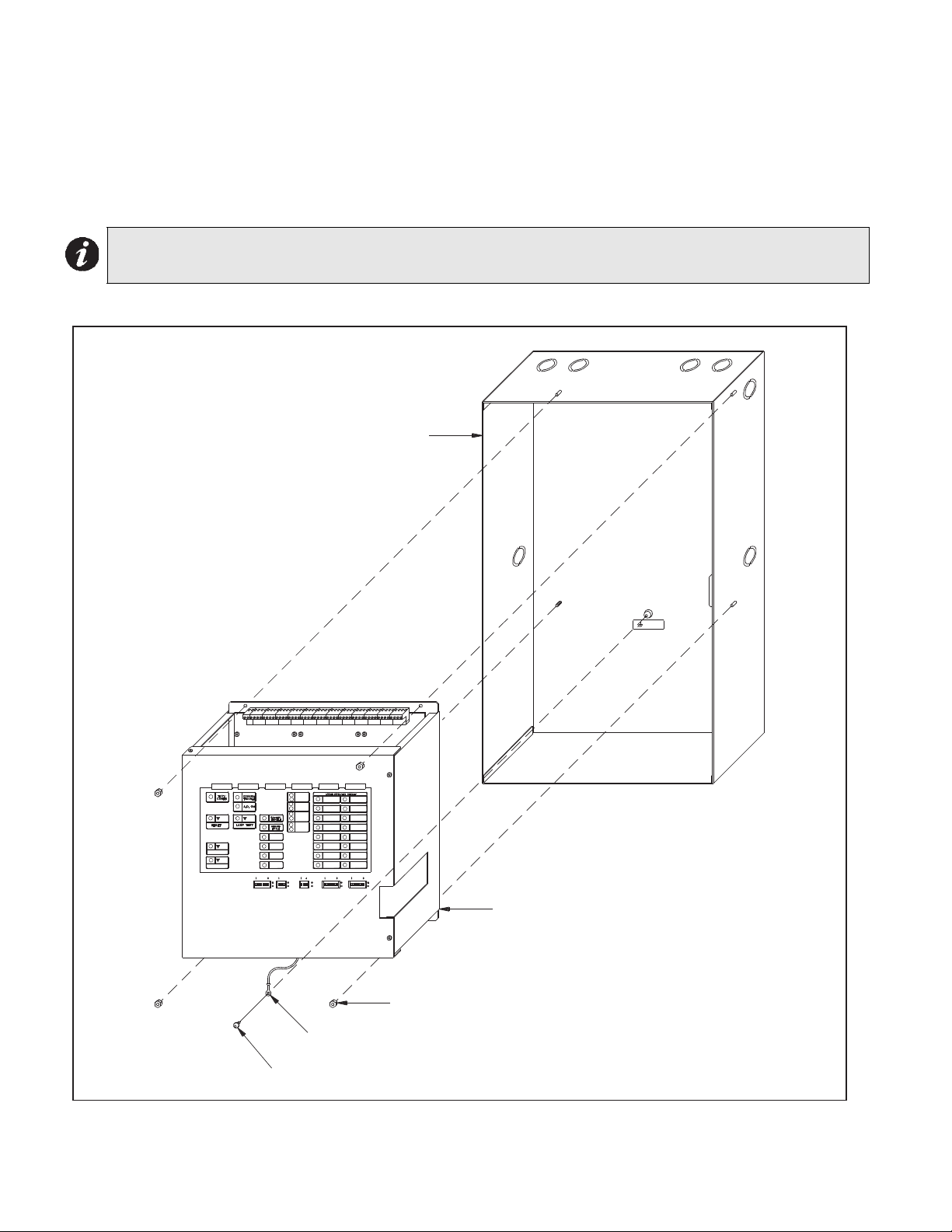
Install the BPS-1100 enclosure as shown below in Figure 1.
Figure 1: BPS-1100 Flush or Surface Enclosure Installation and Dimensions
BPS-1100 Installation and Operation Manual
MATERIAL: 18GA (0.048") THICK
COLD ROLLED STEEL
FINISH: PAINTED, EXCEPT
FOR HINGES
14-1/2"
11"
2" TYP.
1-1/2"
1-3/4"
4-9/16"
DOOR
BACKBOX
1-1/8" & 7/8"
KNOCKOUTS
1-3/4"
SURFACE
(SIDE VIEW)
17"
WALL
DOOR
FLUSH TRIM
1"
FLUSH
(SIDE VIEW)
14-3/4"
BACKBOX
WALL
26"
4-1/2"
10-1/2"
16"
7-1/2"
1-1/4"
TYP.
7/32" DIA.
MOUNTING
HOLE
BACKBOX
28-1/2"
FLUSH TRIM
(MODEL FA-1024TR)
26-1/4"
DOOR
5
Page 12
4.0 Mechanical Installation and Dimensions
MAIN CHASSIS
EARTH GROUND LUG
GROUND
CHASSIS
BACKBOX
#8-32 HEXNUTS (4X)
#8 x 1/4" TYPE `B' SCREW
SELECT
CONFIRM
INPUT 4
INPUT 3
INPUT 2
INPUT 1
OUTPUT 1
OUTPUT 2
OUTPUT 3
OUTPUT 4
OUTPUT 5
OUTPUT 6
OUTPUT 1
OUTPUT 7
OUTPUT 8
OUTPUT 9
OUTPUT 10
OUTPUT 11
OUTPUT 12
OUTPUT 13
OUTPUT 14
OUTPUT 15
OUTPUT 16
OUTPUT 17
OUTPUT 18
OUTPUT 19
OUTPUT 20
CONFIG. O/P ZONE
DISCONNECT
I/P ZONE
DISCONNECT
O/P ZONE
DISCONNECT
O/P ZONE
DISCONNECT
4.1 Main Chassis Installation
The Main Chassis is pre-installed in the BPS-1100 Enclosure as shown. Group the incoming wires through the top of
the enclosure to prepare it for wiring to the Modules. Do not run the wires in-between the Modules since it could
cause a short circuit. Use a wire tie to group wires for easy identification and neatness. Be sure to connect a solid
Earth Ground (from building system ground / to a cold water pipe) to the Chassis Earth Ground Mounting Lug, and
to connect the Earth Ground Wire Lugs from the Main Chassis to the ground screw on the Backbox.
Note: DO NOT install cable through bottom of the box. This space is reserved for Batteries.
Figure 2: Main Chassis Installation
6
Page 13
BPS-1100 Installation and Operation Manual
5.0 Modules Mounting Locations
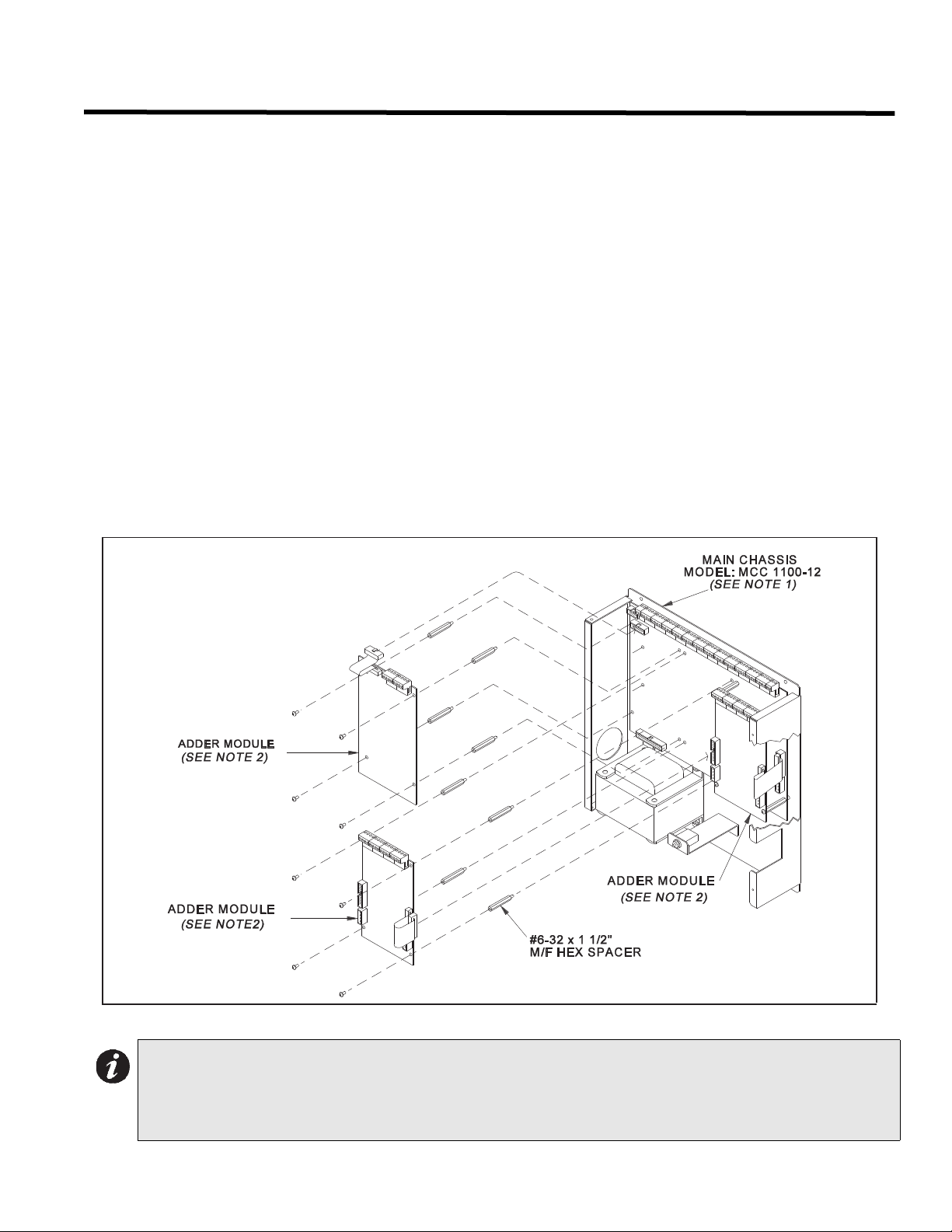
The Main Chassis in a BPS-1100 enclosure comes pre-assembled with all power supply, main panel, and display
components and boards. Signal Adder Modules are installed from right to left using the supplied stand-offs, as
shown in the figure below, with the first Module plugging its 26 pin ribbon cable into P5 on the Main BPS-1100
Board, and using the included MD-579 four wire power cable as described in the Module Settings section. A second
Signal Adder Module would connect by plugging its 26 pin cable into the matching socket on the previous module to
the right, and by installing the supplied MD-579 four wire power cable as described in the appropriate Module
Settings section.
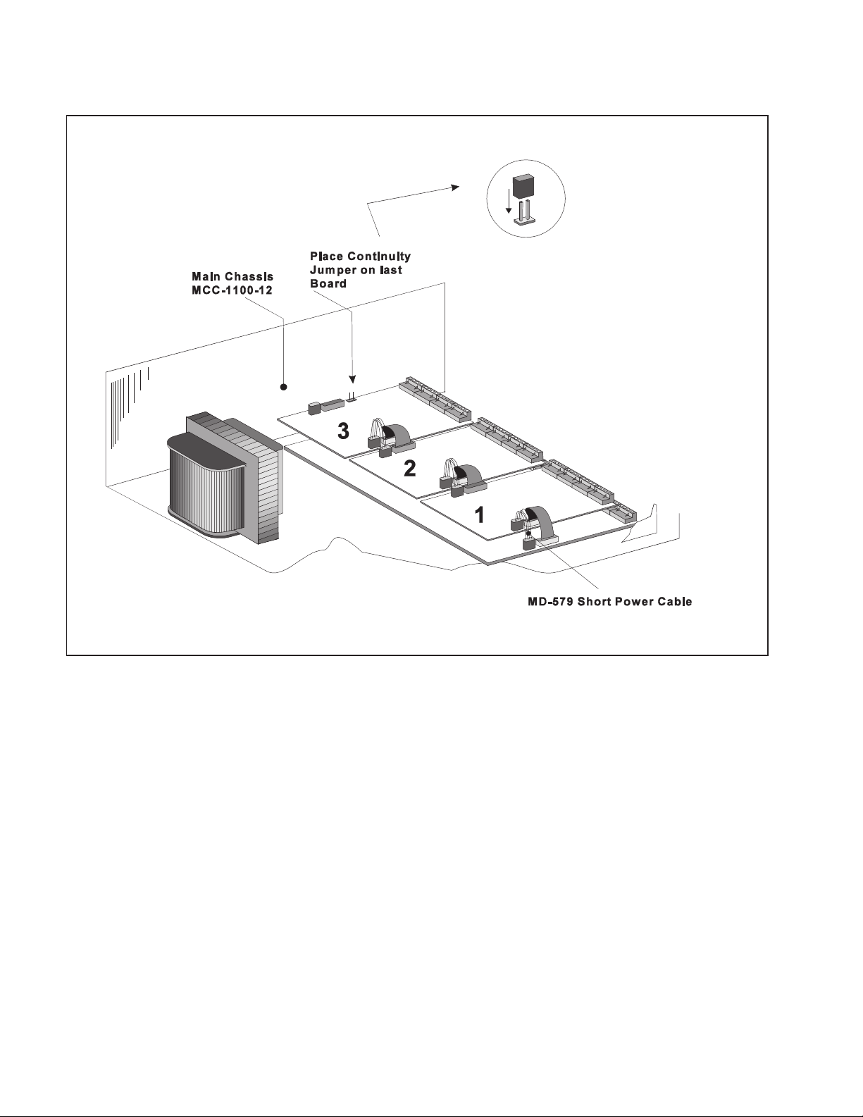
To enable communication from the Main BPS-1100 Board to all of the Circuit Adder Modules, it is necessary to
remove the Continuity Jumper on JW6 (near P5, the Signal Adder Module Connector) on the Main BPS-1100
Board. This jumper plug must be installed on the Continuity Jumper on the last installed Signal Adder Module (see
the appropriate Module Settings section to verify the location of the Continuity Jumper on a particular Signal Adder
Module). Only the LAST Signal Adder Module should have a jumper plug on its Continuity Jumper; all others must
be left without a jumper plug.
There needs to be enough Display Points for each circuit on an Adder Module, and these are assigned during
Configuration (see System Configuration Section) in the order in which the Adders are electrically installed (the
order in which they have their cables connected to each other). Both the number of points available for each Display
Type, and the number required for each Circuit Adder Module Type are described in the Module Settings Section.
Figure 3: Module Mounting Locations
Notes: 1. Front plate is not shown.
2. Adder modules may be:
A) Model SGM-1004A
B) Model RM-1008A
7
Page 14
5.0 Modules Mounting Locations
Figure 4: Adder Module Mounting Details
8
Page 15

BPS-1100 Installation and Operation Manual
6.0 Module Settings
6.1 Main Chassis Board of the BPS-1100
JW6 This Continuity Jumper is removed if there are any Adder Modules (Signal and Relay) installed, and
installed on the last Adder Module.
W1 Cut this jumper to disable ground fault detection on the BPS-1100. Therefore, there will be no ground fault
detection other than from the Fire Alarm Panel.
P3 Connector for front Display Module (part of MCC-1100).
P5 Connector for Adder Modules.
P6 Power Connector for Adder Modules.
P7,8 Factory connection to Bridge Rectifier.
P9,10 Connection to 24 VDC Battery.
F1 20 Amp 1.25" Fast Blow Battery Charge Fuse
Figure 5: Main Chassis board of the BPS-1100
9
Page 16

6.0 Module Settings
CONFIG.
O/P ZONE
DISCONNECT
I/P ZONE
DISCONNECT
O/P ZONE
DISCONNECT
O/P ZONE
DISCONNECT
6.2 Main Display Module (Part of Main Chassis)
P1 Cable connects to P3 of Main Chassis Board of the BPS-1100.
SW1 Dip Switch used for configuration of input and output circuits.
SW2, SW4, SW5 Dip Switches used for output circuit disconnect (labelled O/P Zone Disconnect). See 10.0
System Configuration on page 24.
SW3 Dip Switch used for input circuit disconnect (labelled I/P Zone Disconnect). See 10.0 System
Configuration on page 24.
The Main Display Module provides 4 dedicated Display Points for the 4 Indicating Circuits on the Main BPS-1100
Module. It also provides the following general purpose Display Points.
Chassis Type Display Points
MCC-1100-12 There are 4 Display Points dedicated to the 4 Main Board Indicating Circuits. The next 4 are
dedicated to the 4 Main Board Input Circuits and the next 16 for the Adder Indicating.
Figure 6: Main Display Module (For Service Personnel)
10
Page 17

BPS-1100 Installation and Operation Manual
6.3 Signal Adder Module (Model SGM-1004A)
P2 Data Cable to P5 of Main BPS-1100 Module or to previous Adder Module.
P1 Data Connector for next Adder Module.
P4 Power Connector to P6 of Main BPS-1100 Module or to previous Adder Module.
P3 Power Connector for next Adder Module.
JW1 Continuity Jumper removed if there are any more Adder Modules installed.
JW2 Leave Jumper as packed for this BPS-1100.
JW3 Leave Jumper as packed for this BPS-1100.
JW4 Leave Jumper as packed for this BPS-1100.
JW5 Leave Jumper as packed for this BPS-1100.
J11 NOT USED for BPS-1100.
Jumper JW6 on the Main BPS-1100 Module must be removed if there are any Adder Modules installed.
Note: The SGM-1004A requires 4 display points.
Components
There are 4 green LEDs on the board, one for each signal zone. The LED will illuminate or flash following the signal
rate sent to its zone. It will be off when the system is normal and they will illuminate when a signal zone is activated.
The LED does not reflect what is happening on the signal zone, just that it is receiving data to activate that signal
zone. Jumpers JW2, JW3, JW4 and JW5 are positioned on pins 2 and 3 (right two pins with board orientation as
shown above) from factory. Leave as is for BPS-1100.
Figure 7: Signal Adder Module
11
Page 18

6.0 Module Settings
6.4 Relay Adder Module (Model RM-1008A)
P2 Data Cable to P5 of Main BPS-1100 Module or to previous Adder Module.
P1 Data Connector for next Adder Module.
P4 Power Connector to P6 of Main BPS-1100 Module or to previous Adder Module.
P3 Power Connector for next Adder Module.
JW1 Continuity Jumper removed if there are any more Adder Modules installed.
Jumper JW6 on the Main BPS-1100 Module must be removed if there are any Adder Modules installed.
There is one green LED per each relay (total of eight on each board), which illuminates steadily when the
corresponding relay is active.
Figure 8: Relay Adder Module
12
Page 19

BPS-1100 Installation and Operation Manual
7.0 Field Wiring
7.1 Main Board Terminal Connections
Wire devices to terminals as shown below. See 7.5 Wiring Tables & Information on page 18 and Appendix A -
Module Specifications And Features on page 30 for specifications.
Caution: Do not exceed power supply ratings: Main Chassis, total current for Indicating Circuits is 11A max.
Note: The Terminal Blocks are “depluggable” for ease of wiring.
All power limited circuits must use type FPL, FPLR, or FPLP power limited cable
Figure 9: Main BPS-1100 Module Terminal Connections
BPS-1100 MAIN BOARD
47K E.L.R.
TO NEXT
COMPATIBLY
LISTED
ADDRESSABLE
DEVICE
FIRE ALARM PANEL TROUBLE
ONLY INPUT ZONE
ADDRESSABLE LOOP
-
+
BLK
RED
VIOLET+YELLOW
-
+
FX-2000
FIRE
ALARM
-
PANEL
M501MA MINI
MODULE
FOR FURTHER
DETAILS SEE
INSTALLATION
INSTRUCTIONS
PACKED WITH
MODULE. NOTE:
MODULE TO BE
MOUNTED IN
SEPARATE
ELECTRICAL BOX.
13
Page 20

7.0 Field Wiring
INPUT 1 (POWER LIMITED)
INPUT 2 (POWER LIMITED)
INPUT 3 (POWER LIMITED)
INPUT 4 (POWER LIMITED)
N.C.
N.O.
N.C.
N.O.
N.C.
N.O.
N.C.
N.O.
Figure 10: Main BPS-1100 Module Terminal Connections (continued)
Note: All power limited circuits must use type FPL, FPLR, or FPLP power limited cable
Initiating Circuits are fully supervised and rated for 22 VDC, 3mA standby, 5 mV ripple, 50mA max.
alarm. They may be configured as required. The alarm threshold is 21mA. Maximum loop resistance
is 100 ohms, 50 ohms per side.
Indicating Circuits are fully supervised and rated for 24 VDC unfiltered 1.7 amp Max. They must be
wired as shown in the wiring tables.
14
Page 21

BPS-1100 Installation and Operation Manual
7.2 Signal Adder Module (SGM-1004A) Terminal Connections
The Signal Adder Module provides 4 supervised indicating (signal) circuits, Class A (Style Z) or Class B (Style Y).
Wire devices to terminals as shown below. See 7.5 Wiring Tables & Information on page 18 and Appendix A -
Module Specifications And Features on page 30 for specifications.
Note: The Terminal Blocks are “depluggable” for ease of wiring.
Figure 11: Signal Module Terminal Connections
15
Page 22

7.0 Field Wiring
7.3 Relay Adder Module (RM-1008A) Terminal Connections
The Relay Adder Module provides 8 relay contacts. Wire devices to terminals as shown below. See 7.5 Wiring
Tables & Information on page 18 and Appendix A - Module Specifications And Features on page 30 for
specifications.
Note: The Terminal Blocks are “depluggable” for ease of wiring.
All power limited circuits must use type FPL, FPLR, or FPLP power limited cable. All relay circuits
must be connected to a listed power limited source of supply.
Figure 12: Relay Adder Module Terminal Connections
16
Page 23

7.4 Power Supply Connections
The power supply is part of the Main Chassis. The ratings are:
Electrical input ratings 120 VAC, 60 Hz, 2 A / 240 VAC, 50 Hz, 1A
Power supply total current 11 A maximum
Battery Fuse on Main Module Replace with 20 Amp, 1-1/4" Fast Acting Fuse
Caution: Do not exceed power supply ratings. See Appendix A - Module Specifications And Features on
page 30 for specifications. Wire as shown using proper wire gauges.
Figure 13: Power Supply Connections
BPS-1100 Installation and Operation Manual
17
Page 24

7.0 Field Wiring
7.5 Wiring Tables & Information
Table 1: Wiring Table for Input Circuits
Wire Gauge Maximum Wiring Run to Last Device (ELR)
(AWG) ft m
22 2990 910
20 4760 1450
18 7560 2300
16 12000 3600
14 19000 5800
12 30400 9200
Note: Maximum Loop Resistance Should Not Exceed 100 Ohms
Table 2: Wiring Table for Indicating Circuits
TOTAL
SIGNAL
LOAD
Amperes ft m ft m ft m ft m Ohms
0.06 2350 716 3750 1143 6000 1829 8500 2591 30
0.12 1180 360 1850 567 3000 915 4250 1296 15
0.30 470 143 750 229 1200 366 1900 579 6
0.60 235 71 375 114 600 183 850 259 3
0.90 156 47 250 76 400 122 570 174 2
1.20 118 36 185 56 300 91 425 129 1.5
1.50 94 29 150 46 240 73 343 105 1.2
1.70 78 24 125 38 200 61 285 87 1.0
Note: Main Board Indicating Circuits are rated for 1.7 Amperes each.SGM-1004A Indicating Circuits are
rated for 1.7 Amperes each.
MAXIMUM WIRING RUN TO LAST DEVICE (ELR)
18AWG 16AWG 14AWG 12AWG
MAX. LOOP
RESISTANCE
Note: Maximum Voltage Drop Should Not Exceed 1.8 Volts
Auxiliary Power Wiring
Use Table 2: Wiring Table for Indicating Circuits above.
18
Page 25

BPS-1100 Installation and Operation Manual
8.0 System Checkout
8.1 Before Turning The Power "ON"
1. To prevent sparking, do not connect the batteries. Connect the batteries after powering the system from the main AC supply.
2. Check that all Adder Modules are installed in the proper location with the proper connections.
3. Check all field (external) wiring for opens, shorts, and ground.
4. Check that all interconnection cables are secure, and that all connectors are plugged-in properly.
5. Check all Jumpers and Switches for proper setting.
6. Check the AC power wiring for proper connection.
7. Check that the chassis is connected to EARTH GROUND (cold water pipe).
8. Make sure to close the front cover plate before powering the system from main AC supply.
8.2 Power-up Procedure
1. After completing the System Checkout procedures, power-up the panel. The green "AC-ON" LED should illuminate, the “Common Trouble” LED should illuminate.
2. Since the batteries are not connected, the "Battery Trouble" LED should illuminate, the “Common Trouble” LED should flash and the Trouble Relay (on the main BPS-1100 board) will be active.
3. Connect the batteries while observing correct polarity; the red wire is positive (+) and black wire is negative (-).
4. All indicators should extinguish except for normal power "AC-ON" green LED.
8.3 Troubleshooting
Circuit Trouble
Normally when a Circuit trouble occurs, its designated trouble indicator will be illuminated, as well as the common
trouble indicator and the common trouble relay will be active. To correct the fault, check for open wiring on that
particular Circuit loop or if the Circuit Disconnect Switch is in the on or closed position.
Note: Disconnecting a Circuit will cause a system trouble (off-normal position).
Ground Fault
This panel has a common ground fault detector. To correct the fault, check for any external wiring touching the
chassis or other Earth Ground connection.
Battery Trouble
Check for the presence of batteries and their conditions. Low voltage (below 20.4V) will cause a battery trouble. If
battery trouble condition persists, replace batteries as soon as possible.
Configuration. Mode
If the Test/Config LED is illuminated steady, the system is in Configuration Mode. If it is flashing then the
Configuration has been corrupted, and has been reset to defaults; it is then necessary to review / re-enter your
Configuration.
Common Trouble
If only a common trouble is indicated on the main panel and none of those above confirming trouble indicators are
on, then check the following for possible fault:
i) Check for any missing interconnection wiring.
ii) Check for any Adder Module missing that was part of the Configuration.
iii) Check jumper positions; particularly ensure that the Continuity Jumper is installed only on the LAST Adder
Module in the system.
iv) Check for improperly secured cabling.
19
Page 26

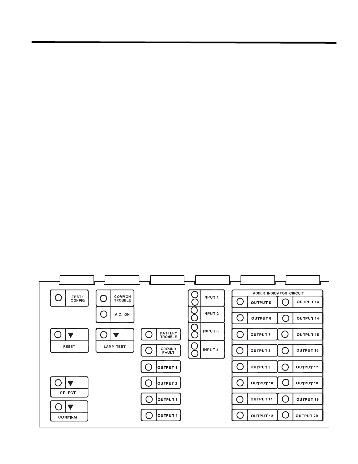
9.0 Indicators, Controls, & Operation
9.0 Indicators, Controls, & Operation
Refer to the following LED Indicators and Control Buttons and Switches locations.
Figure 14: Indicators and Control Location
The Main Display Panel on the BPS-1100 Signal Booster Power Supply consists of the following.
7 common LED Indicators
2 Common Buttons Reset and Lamp Test
2 Configuration Buttons Select and Confirm
2 Configuration LED Indicators Select and Confirm
8 Input Indicators 1 red and 1 amber per each Input Zone 1 to 4.
20 Output Indicators: 1 amber LED per each Output Zone 1 to 20.
20 Output (O/P) Disconnect DIP
Switches
Configuration DIP Switch
(marked CONFIG.)
LED Indicators may be Amber, Red, or Green, and may illuminate continuously (steady), or at one of two Flash
Rates.
Fast Flash 120 flashes per minute, 50% duty cycle
Trouble Flash 20 flashes per minute, 50% duty cycle
Test/Config, Common Trouble, A.C. ON, Reset, Lamp Test, Battery Trouble and
Ground Fault.
1 DIP switch for each Output Zone 1 to 20.
8 DIP switches for programming.
20
Page 27

BPS-1100 Installation and Operation Manual
9.1 Common Indicators
AC On LED
The AC On Indicator is activated steady green while the main AC power is within acceptable levels. It is turned off
when the level falls below the power-fail threshold and the panel is switched to standby (battery) power.
Common Trouble LED
The Common Trouble Indicator flashes amber at the Trouble Flash Rate when there is any Trouble condition being
detected on the panel. It is turned off when all Troubles are cleared.
Select LED
This LED is used for selection in the configuration mode.
Confirm LED
This LED is for confirmation of configuration selections.
Configuration / Test Mode LED
The Configuration / Test Mode Indicator is turned on steady amber to indicate that the Panel is in Configuration
Mode. If the Panel is left in Configuration Mode for over an hour with no operator activity, this Indicator will flash at
the Trouble Rate.
Battery Trouble LED
The Battery Trouble Indicator flashes amber at the Trouble Rate when the Battery is either low (below 20.4 VDC), or
disconnected.
Ground Fault LED
The Ground Fault Indicator flashes amber at the Trouble Rate when the Ground Fault Detector detects a Ground
Fault on any field wiring. It is turned off when the Ground Fault is cleared.
Lamp Test LED
The Lamp Test amber illuminates steadily as long as the Lamp Test Button is pressed and indicates a Lamp Test is
in progress.
Reset LED
The Reset amber LED illuminates steadily when the Reset Button is pressed and as long as the reset is in
progress.
9.2 Common Controls
Reset Button
This button is used for Configuration only.
Select Button
This button is used to select features in the configuration mode, otherwise it does nothing.
Confirm Button
This button is used to confirm selected features in the configuration mode, otherwise it does nothing.
Lamp Test Button
Activation of the Lamp Test button turns all front panel Indicators on steady. If Lamp Test is active for more than 10
seconds, Common Trouble is activated.
21
Page 28

9.0 Indicators, Controls, & Operation
9.3 Circuit Status Indicators
There are two LEDs for each Input Circuit and one LED for each Indicating and Relay Circuit. For the 4 Input
Circuits, they are labelled Input 1,2, 3, and 4. For the first four Indicating Circuits on the Main Board, these are
labelled Output 1, 2, 3 and 4. For all other Adder Modules these are arranged in columns of eight indicators
numbered from 5 to 12 - top to bottom and 13 to 20. Each Circuit Status LED for the input circuits is red and is on
steadily to indicate active input. Each Circuit Trouble LED (for both input and indicating) is Amber and in general
flashes at the Trouble Flash Rate when active.
Note: Indicating and output terms are used interchangeably.
Input Circuit Status Indicators
This operation applies to Input Circuits configured as alarm. The Circuit Trouble Indicator flashes at the Trouble
Rate to indicate circuit trouble (open circuit) or if the circuit is Disconnected. The Trouble LED is always turned off
when the Input Circuit is active. The Circuit Status Indicator is activated steady red when the Input Circuit is active.
This Circuit Status Indicator will illuminate at the Fast Flash rate while an active circuit is reconnected (after being
Disconnected).
Note: Inputs must be steady for BPS-1100 outputs to be active. The BPS-1100 will not respond to pulsing
input contacts.
Output Circuit Indicators
This operation applies to Output Circuits of any type. The Circuit Trouble Indicator flashes amber at the Trouble Rate
to indicate short-circuit or open-circuit trouble, or if the circuit is Disconnected.
Relay Circuit Indicators
Relay Circuit Trouble Indicators flash amber at the Trouble Rate while the circuit is Disconnected.
9.4 Circuit (Zone) Disconnect Switches
Circuit (Zone) Disconnect Switches are provided for all Indicating and Relay Circuits on the BPS-1100. For the first
four Indicating Circuits on the Main Board, the Disconnect Switches consist of a bank of DIP Switches. For DIP
Switches, numbers 1 to 8 correspond to the Circuits indicated in the Indicator column from top to bottom. Changing
a Circuit Disconnect Switch to the ON position bypasses the associated Circuit and turns on its Trouble Indicator,
also activating Common Trouble. While a Circuit is Disconnected, all changes in status (Troubles) on that Circuit are
ignored. Disconnected Indicating Circuits are not activated by the Input Circuits. Disconnecting an active Indicating
Circuit immediately deactivates the Circuit. Note: indicating and output terms are used
Note: indicating and output terms are used interchangeably.
These Disconnect Switches are also used during Configuration Mode as described in those sections.
22
Page 29

BPS-1100 Installation and Operation Manual
9.5 Circuit Types
Input Circuits Types
Alarm Input
This is a “Normal” type of Alarm which may have an alarm contact attached to it. Any activation of this contact will
immediately result in an Alarm condition. An Alarm condition causes the associated Input Circuit Status LED to
illuminate Red. All output circuits configured to this input will activate at alert rate. De-activation of this input will turn
off all of the outputs configured to this input.
General Alarm Input
This input follows the Fire Alarm Panel set to two stage operation. In single stage these inputs act the same as
Alarms, but if Correlations are enabled, General Alarm Input Circuits are correlated to ALL Indicating Circuits.
General Alarm Inputs activate outputs at configured evacuation rate.
Indicating (Output) Circuits Types
Signal
For audible devices such as bells and piezo mini-horns. While sounding, these follow the pattern appropriate for the
condition; the configured Evacuation Code (default is Temporal Code) during Single-Stage Alarm, or Two-Stage
General Alarm, or the Alert Code during Two-Stage’s Alert (First) Stage.
Strobe
For visual devices such as strobes that use no code pattern (they are continuous) and follow input contact.
Evacuation Codes
Single stage codes
Continuous On 100% of the time
Temporal Code 3 of 0.5 second on, 0.5 second off then, 1.5 second pause
March Code 0.5 second on, 0.5 second off
California Code 5 seconds on, 10 seconds off
Two-stage codes:
Alert Code 0.5 second on, 2.5 seconds off
General Alarm Evacuation code as selected from above.
Figure 15: Evacuation Codes
CONTINOUS
0.5s
0.5s
0.5s
0.5s
1.5s
TEMPORAL CODE
MARCH CODE
5s 10s
0.5s
2.5s
CALIFORNIA CODE
ALERT CODE
23
Page 30

10.0 System Configuration
10.0 System Configuration
10.1 Introduction To Configuration
Configuration of the BPS-1100 is performed by a combination of Configuration DIP Switch settings and button
presses. Circuit (Zone) related operations are correlated to their respective Disconnect Switches.
The Configuration DIP Switches are accessible from the Main Display Module after removing a protective Lexan
cover with two screws, and are labeled as CONFIG. 1 to 8. The Circuit (Zone) Disconnect Switches are re-defined
as Circuit (Zone) Select during Configuration. Caution should be used to reset the Zone Disconnect Switches back
to the desired settings before exiting configuration mode. Normal system operation is suspended while
Configuration Mode is active. Configuration Mode is entered whenever any of the Configuration DIP Switches are
set as per functions listed in the Configuration DIP Switch Function Table and exited by turning them all OFF (put
switches in the bottom or OFF positions), then performing a RESET.
While in Configuration Mode the BPS-1100 Is Not Operating!
Two buttons and LED indicators are used in Configuration Mode.
Select
This is a “Select Setting” button and the LED indicator may show current status of a function.
Confirm
This is a “Confirmation” button for some functions, used together with the Select button.
All other buttons are non-functional during Configuration Mode.
Figure 16 below shows the positions of the Configuration DIP Switch and the Select and Confirm Buttons.
Configuration Functions are selected by the Configuration DIP Switches. as shown on Table 3: Configuration Dip
Switch Function Table on page 25
Note: A Switch position of “0" is “OFF” (bottom position) and “1" is “ON” (top position).
Figure 16: Configuration Indicators and Controls
24
Page 31

Table 3: Configuration Dip Switch Function Table
Configuration Dip Switch Function Table
BPS-1100 Installation and Operation Manual
Dip Switch Position
(1-8)
0000 0000 00 None Normal Operation (Not in Configuration Mode)
0000 0100 04 Select Two Stage Operation Features
0000 0110 06 Select Output Circuit Correlations Enabled
0000 1101 0D Select Evacuation Code Selection
0001 0010 12 Select Signal Circuit Isolator Option
0010 0000 20 Select Alarm Input
0010 0110 27 Select General Alarm
0010 0100 24 Select Non-latching Supervisory
0011 0000 30 Select Signal
0011 0010 32 Select Strobe
0011 0011 33 Select Non-silenceable Strobes
0011 1000 38 None Show Relay Circuits Relays
0100 0000 40
Function
Number
Button
Operations
Select &
Confirm
Description
Indicating Circuits/
Signal Zones
Set Circuit Adder Module Number & Type Resize System
0100 0001 41 Select Correlation by Input Circuit Correlations
0100 0010 42 Select Correlation by Output Circuit
0111 1111 7F
Select &
Confirm
Restore to Default Configuration Default
10.2 Entering Configuration Mode
The System enters Configuration Mode whenever any of the Configuration DIP Switches 2 to 8 are set to a “1" or
ON position (top position). The TEST / CONFIG MODE and COMMON TROUBLE LEDs will turn ON.
The BPS-1100 is not operating as a Signalling System while in Configuration Mode.
If there is no activity (no buttons pressed or switches changed) for one hour, the System will return to normal
operation, but will remain in trouble.
As Configuration DIP Switches are changed to select different functions, wait for a few seconds for the appropriate
LEDs to change as the System recognizes the change.
Note: Configuration changes take effect immediately as they are made; there is no “undo” function.
10.3 Exiting Configuration Mode
To exit Configuration Mode, after all desired changes are made, all Configuration DIP Switches must be returned to
a “0" or OFF position (bottom position). Wait about five seconds, then press the RESET button. The System should
now be back in Normal Operation.
25
Page 32

10.0 System Configuration
10.4 Factory Default Configuration
The system as shipped from the factory is configured with no Adder Modules, and with certain set defaults. The
Default settings are below.
• All Input Circuits are Style B (Class B) Alarms (any Alarm on any input circuit activates all output circuits)
• Indicating Circuits are all Common Alarm and set as Signal, Temporal Code. If shorts exist on any indicating
circuits, then they will not activate on alarms
• All Indicating and Relay correlations are set to Common Alarm activation
• Aux Disconnect will disconnect correlated relays
• Relay Adder(s) activate only on Common Alarm
• System assumes there are no Adder Modules
10.5 Restore To Default / Resize
Restoring the System to the Default Configuration is performed whenever it is desirable to restore the Factory
Default Configuration, and also whenever Circuit Adder Modules (Signal or Relay) are added, removed, or
rearranged.
Restore Defaults - Style B / Class B
• Set Config DIP Switch to 0111 1111 (R e s tore D e faul ts ) .
• Wait 5 seconds.
• Press Select & Confirm Buttons together for 5 seconds.
• Wait 5 seconds.
• Set Config DIP Switch to 0100 0000 (Resize System *).
• Wait 5 seconds.
• Press Select & Red Buttons together for 5 seconds.
• Wait 10 seconds.
10.6 Resize System (Set Adder Module Number & Type)
Resizing the System without performing a full Restore to Defaults may be done if the only change is adding an
Adder Module. It should not be performed other than as part of a full Restore to Defaults, if Adder Modules are
removed, or inserted between existing Modules, otherwise Circuit specific Configuration may be mis-assigned.
For Adder Modules added after existing Modules, in order to Resize
• Set Config DIP Switch to 0100 0000 (Resize System *).
• Wait 5 seconds.
• Press Select & Confirm Buttons together for 5 seconds.
• Wait 10 seconds.
The System is now ready for further Configuration, or Configuration Mode may be exited if the Default Settings for
the added Modules are acceptable.
* During the Resize (Set Adder Module Number & Type) part of the operation, the Select LED flashes to indicate
how many Display Modules and Adder Modules (including the main board) are found. The Select LED flashes for
the number of Display Modules first, followed by the number of Circuit Adder Modules. If no Adder Modules are
found the LED flashes once for the main board, if one Adder Module is found it flashes twice, etc. For example if a
BPS-1100 system has two Adder Modules, the Select LED will flash once for the Main Display Module, pause, flash
three times (once for the main BPS-1100 board and once for each of the adder modules), long pause and repeat.
Note: The Select LED indicates how many Adders (plus the main board) are found, not how many the
System is Configured to accept. If the number of Adders found is different from the number the
System is Configured for, the system will be in trouble.
26
Page 33

BPS-1100 Installation and Operation Manual
10.7 Configuring Features
There are two types of Features; those which are just turned ON and OFF, and those with Multiple Settings. For ON
and OFF Features, the Select LED is lit for ON, and not lit for OFF, and the Select Button is pressed to change the
ON / OFF setting. For Multiple Setting Features, the Select LED flashes a number of times to indicate the setting,
then pauses; the Select Button is used to change the selected setting. Be sure to pause for about 3 seconds after
changing the Configuration DIP Switches, or pressing the Select Button to see the results.
Table 4: Feature Configuration Dip Switch Table
Dip Switch Position
(1-8)
O000 0100 Two Stage Operation Enabled
0000 0110
0001 0010 Signal Circuit Isolator Option
0011 1000 Show Relay Circuits All Display Points assigned to Relay Circuits will be lit.
0000 1101
Feature Description
Select LED lit indicates that the System is set for Two
Stage which means the normal alarm will activate the
outputs at the Alert Rate and the general alarm will
activate the outputs at the Evac rate.
Select LED lit indicates that Output Circuits (Indicating
Output Circuit Correlations
Enabled
Audible Indicating Circuit
Evacuation Code
Circuits and Relays) operate according to any set
Correlations (see Correlation section). If the Select LED
is not lit (default), all Output Circuits are Common
Alarm; all outputs turn on for any Alarm Input.
Select LED lit indicates that if there exists a short circuit
on any Indicating Circuit and an alarm condition follows,
then those Indicating Circuits will be activated anyway. If
Select LED is not lit (default), then under same
conditions, the Indicating Circuits will not be activated to
prevent wasting power. This feature is needed when
Signal Isolator Devices are employed so that Indicating
Circuits will be activated even under shorted conditions.
Select LED flashes 1 time = Continuous
Select LED flashes 2 times = March Time
Select LED flashes 3 times = Temporal Code (default)
Select LED flashes 4 times = California Code
27
Page 34

10.0 System Configuration
10.8 Configuring Indicating Circuits:
Indicating Circuits (Signal Zones) are Configured by using the Configuration DIP Switches to select the desired
Circuit Type Function, along with the Circuit Trouble LED and Disconnect Switches. When a Circuit Type is selected
by the Configuration DIP Switch setting, the Amber Trouble LED for each Circuit currently configured as that type
will light. To configure Circuits to be of that selected Circuit Type, all of the desired Circuit Disconnect Switches are
turned ON (up position) and the Select Button is pressed for about one second. After a short pause, the Input Circuit
Amber Trouble LED will be updated to show the new configuration.
Notes: Any subsequent selection of a particular Circuit as a different Circuit Type will supercede the
previous selection.
The physical Circuit Type must be appropriate for the selected Circuit Type; for example only
Indicating Circuits can be configured as Strobes.
Extra Auxiliary Power
The BPS-1100 with firmware 1.0.3 and higher now allows the signal output circuits as an auxiliary power supply. To
use this feature you must program an input zone to “Non-latching supervisory” and the selected output circuit to be
used as an auxiliary power supply as “Non-silenceable strobe”. Then make sure the appropriate non-latching
supervisory input is permanently shorted and correlated to the non-silenceable strobe output circuit (now being used
as an auxiliary supply).
Be sure to reset Circuit Disconnect Switches To Off (Down Position) before attempting to configure
any other Circuits!
As an example, if in a System with four Indicating Circuits (Main Board only), we wanted Class B operation, and the
last Indicating Circuit as a Strobe, the following sequence would be used.
• Turn off all Disconnect Switches for the first four outputs.
• Set Config DIP Switch to 0011 0000; all four Output Amber Trouble LEDs should light.
• Set Config DIP Switch to 0011 0010; all four Indicating Amber Trouble LEDs should go out.
• Set only Indicating Circuit Output 4 Disconnect Switch ON.
• Press the Select Button for one second; after a pause the Amber Trouble LED for Output 4 should light.
• Turn OFF all Disconnect Switches, wait 5 seconds.
• Exit Configuration Mode by pressing Reset button.
28
Page 35

BPS-1100 Installation and Operation Manual
10.9 Configuring Circuit Correlations:
As a working definition for Correlations, Circuits can be defined as listed below.
Input Circuits = Input contacts
Output Circuits = Indicating Circuits (Signal Zones), and Relay Circuits.
With the Factory Default Configuration, all Outputs are configured to activate with any Inputs configured as
Alarms. If Output Circuit Correlations are enabled (see the Configure Features section), Outputs must be
configured to one or more Inputs to activate at all. This configuration is referred to as a Correlation. There are two
configuration options; correlated individual Outputs to one or more Inputs, or correlating individual Inputs to one or
more Outputs. Output Circuits may be correlated to as many Input Circuits as desired, and vice-versa.
Correlation by Input Circuit
• Set Config DIP Switch to 0100 0001; pause for about three seconds.
• One and only one Input Circuit’s Disconnect Switch is turned ON (up position). This function will not operate if
more than one Input Circuit Disconnect Switch is turned ON at one time. The selected Input Circuit’s Amber
Trouble LED will light, as well as the Amber Trouble LEDs of any Output Circuits (Indicating / Signal Circuit or
Relay Circuit) that are already Correlated to that Input. If only a check of Correlations is desired, then this is the
only step required, and you may step through from one Input Circuit to another, one at a time.
• If it is desired to set new Correlations for the selected Input Circuit, then the Disconnect Switch for desired
Output Circuits are turned ON (up position). The Select Button is pressed for one second; after a pause the
Amber Trouble LEDs for the newly Correlated Output Circuits will be lit.
Correlation by Output Circuit
• Set Config DIP Switch to 0100 0010; pause for about three seconds.
• One and only one Output Circuit’s (Indicating Circuit / Signal Zone, or Relay Circuit) Disconnect Switch is
turned ON (up position). This function will not operate if more than one Output Circuit Disconnect Switch is
turned ON at one time. The selected Output Circuit’s Amber Trouble LED will light, as well as the Amber
Trouble LED’s of any Input Circuits (Initiating Circuit / Detection Zone) that are already Correlated to that
Output. If only a check of Correlations is desired, then this is the only step required, and you may step through
from one Output Circuit to another, one at a time.
• If it is desired to set new Correlations for the selected Output Circuit, then the Disconnect Switch for desired
Input Circuits are turned ON (up position). The Select Button is pressed for one second; after a pause the
Amber Trouble LEDs for the newly Correlated Input Circuits will be lit.
At present, only the following types of Circuit Correlations are possible.
• Input Circuits to Indicating Circuits or Relays.
• Confirm Circuits to Relays (they are automatically Correlated to ALL Indicating Circuits).
IMPORTANT: The Feature Output Circuit Correlations Enabled must be ON for Indicating Circuit
Correlations to operate (see the Configure Features section), otherwise all Indicating Circuits
will be “Common Alarm”; they will all activate with any Input Circuits. Relay Circuits are always
Enabled for Correlations.
10.10 Display Configuration
The Main Display Module on the front panel is automatically updated to display all circuits found whenever the
function Resize - Adder Module Number & Type Configuration is performed. The Main Display Module has
dedicated Trouble LEDs for the four Indicating Circuits on the Main BPS-1100 Module. Any Adder Module circuits
are displayed after the base system input circuits in the same order as the Adder Modules have been installed (that
is from right to left). For example, if there is one 8 Relay Adder module and one 4 Signal Adder module, the Main
Display will annunciate 8 Relay Circuits followed by 4 Indicating Circuits. Refer to the Figure shown under the
Indicators, Controls, & Operation section.
29
Page 36

Appendix A - Module Specifications And Features
Appendix A - Module Specifications And Features
Main Chassis Signal Adder Module (SGM-1004A)
General
4 supervised Style B (Class B) Initiating Circuits; fully
configurable. Terminals are labelled “INI”.
Power limited: 22 VD, 3mA standby, 5mV ripple, 50mA
max. (alarm)
4 Style Y or Z (Class B or A) Indicating Circuits;
configurable as strobes or audibles. Terminals are labelled
“IND”.
Power limited: 24 VDC unfiltered
1.7 A @ 49E C per Circuit
Up to 3 Circuit Adders may be added.
Displays and Disconnect Switches for up to 24 Circuits. 4
Inputs & 20 Outputs
Aux. Power Supply. Terminals are labelled "AUX PWR".
Power limited: 24 VDC Filtered
1.7 A @ 49E C
Two Power Supplies. Terminals are labelled “4-WIRE”.
Power limited: 22 VDC, 200 mA each max., 300 mA total
max, 5 mV ripple
Auxiliary relays: (resistive loads)
Must be connected to a Listed Power Limited Source of
Supply. Terminals are labelled “GROUND” and “TROUBLE”.
Common Ground: Form C, 1 Amp, 28 VDC
Common Trouble: Form C, 1 Amp, 28 VDC
Micro-controller based design.
Fully Configurable from Front Panel.
Full walk test function.
Electrical Ratings
AC Line Voltage: 120V 60Hz / 240V, 50Hz
2 Amps / 1 Amp (primary)
Power Supply ratings: 12 Amps. max. (secondary)
For Indicating Circuits: 24VDC unfiltered, Power Limited
11 Amps. max. (6.0 Amps for main
board fully loaded)
Battery: 24VDC, Gel-Cell/Sealed Lead-Acid
Charging capability: 10-17 AH batteries
Current Consumption: standby: 200 mA
alarm: 350 mA
4 Style Y or Z (Class B or A) Indicating Circuits; configurable
as strobes or audibles (NOT synchronized). Terminals are
labelled “IND”.
Power limited: 24 VDC unfiltered
Max. 1.7 A @ 49° C per Circuit
Current Consumption: standby: 35 mA
alarm: 150 mA
Relay Adder Module (RM-1008A) (resistive loads)
Must be connected to a Listed Power Limited Source of
Supply. Terminals are labelled “RLY”.
8 fully Configurable Form C Relays.
Form C, 1 Amp., 28 VDC (resistive loads)
Current Consumption: standby: 25 mA
alarm: 150 mA
Compliance
30
System Model: BPS-1100 Signal Booster Power Supply
Applicable Standards: NFPA 72, ULC-S527-99, ULC-S525, ULC-526, ULC-S318
Page 37

BPS-1100 Installation and Operation Manual
Appendix B - Power Supply & Battery Calculations (Selection Guide)
Use the form below to determine the required Main Chassis and Secondary Power Supply (batteries).
IMPORTANT NOTICE
The main AC branch circuit connection for Fire Alarm Control Unit must provide a dedicated continuous power without provision of any disconnect
devices. Use #12 AWG wire with 600-volt insulation and proper over-current circuit protection that complies with the local codes. Refer to
Appendix A - Module Specifications And Features on page 30 for specifications.
Power Requirements (All currents are in amperes)
Model Number Description Qty Standby
MCC-1100-12 Main Chassis (12 Amp) X 0.200 = 0.350 =
SGM-1004A 4 Indicating Circuit Module X 0.035 = 0.150 =
RM-1008A 8 Relay circuit Module X 0.025 = 0.150 =
Signal Load (bells, horns, strobes, and etc.) X
Auxiliary Power Supply =
Total currents (Add above currents) STANDBY (A)(B)
Tot al
Standby
Alarm
Alarm
Total
Alarm
=
=
Total Current Requirement: ALARM (B)______ Amps.
Battery Capacity Requirement:
([STANDBY (A)______ ] X [(24 or 60 Hours)___ ]) + ([ALARM (B)______ ] X [
*Alarm in Hr.] _____) = (C)______AH
Battery Selection: Multiply (C) by 1.20 to derate battery.
Batteries: BA-110(10AH), BA-117(17AH) will fit into the BPS-1100.
*Use 0.084 for five minutes of alarm or 0.5 for thirty minutes of alarm as a multiplier figure.
31
Page 38

Warranty & Warning Information
Warranty & Warning Information
Warning Please Read Carefully
Note to End Users: This equipment is subject to terms and conditions of sale as follows:
Note to Installers
This warning contains vital information. As the only individual in contact with system users, it is your responsibility to
bring each item in this warning to the attention of the users of this system. Failure to properly inform system endusers of the circumstances in which the system might fail may result in over-reliance upon the system. As a result, it
is imperative that you properly inform each customer for whom you install the system of the possible forms of failure.
System Failures
This system has been carefully designed to be as effective as possible. There are circumstances, such as fire or
other types of emergencies where it may not provide protection. Alarm systems of any type may be compromised
deliberately or may fail to operate as expected for a variety of reasons. Some reasons for system failure include:
•Inadequate Installation
A Fire Alarm system must be installed in accordance with all the applicable codes and standards in order to provide
adequate protection. An inspection and approval of the initial installation, or, after any changes to the system, must
be conducted by the Local Authority Having Jurisdiction. Such inspections ensure installation has been carried out
properly.
•Power Failure
Control units, smoke detectors and many other connected devices require an adequate power supply for proper
operation. If the system or any device connected to the system operates from batteries, it is possible for the
batteries to fail. Even if the batteries have not failed, they must be fully charged, in good condition and installed
correctly. If a device operates only by AC power, any interruption, however brief, will render that device inoperative
while it does not have power. Power interruptions of any length are often accompanied by voltage fluctuations which
may damage electronic equipment such as a fire alarm system. After a power interruption has occurred,
immediately conduct a complete system test to ensure that the system operates as intended.
•Failure of Replaceable Batteries
Systems with wireless transmitters have been designed to provide several years of battery life under normal
conditions. The expected battery life is a function of the device environment, usage and type. Ambient conditions
such as high humidity, high or low temperatures, or large temperature fluctuations may reduce the expected battery
life. While each transmitting device has a low battery monitor which identifies when the batteries need to be
replaced, this monitor may fail to operate as expected. Regular testing and maintenance will keep the system in
good operating condition.
•Compromise of Radio Frequency (Wireless) Devices
Signals may not reach the receiver under all circumstances which could include metal objects placed on or near the
radio path or deliberate jamming or other inadvertent radio signal interference.
•System Users
A user may not be able to operate a panic or emergency switch possibly due to permanent or temporary physical
disability, inability to reach the device in time, or unfamiliarity with the correct operation. It is important that all system
users be trained in the correct operation of the alarm system and that they know how to respond when the system
indicates an alarm.
•Automatic Alarm Initiating Devices
Smoke detectors, heat detectors and other alarm initiating devices that are a part of this system may not properly
detect a fire condition or signal the control panel to alert occupants of a fire condition for a number of reasons, such
as: the smoke detectors or heat detector may have been improperly installed or positioned; smoke or heat may not
be able to reach the alarm initiating device, such as when the fire is in a chimney, walls or roofs, or on the other side
32
Page 39

BPS-1100 Installation and Operation Manual
of closed doors; and, smoke and heat detectors may not detect smoke or heat from fires on another level of the
residence or building.
•Software
Most Mircom products contain software. With respect to those products, Mircom does not warranty that the
operation of the software will be uninterrupted or error-free or that the software will meet any other standard of
performance, or that the functions or performance of the software will meet the user’s requirements. Mircom shall
not be liable for any delays, breakdowns, interruptions, loss, destruction, alteration or other problems in the use of a
product arising our of, or caused by, the software.
Every fire is different in the amount and rate at which smoke and heat are generated. Smoke detectors cannot
sense all types of fires equally well. Smoke detectors may not provide timely warning of fires caused by
carelessness or safety hazards such as smoking in bed, violent explosions, escaping gas, improper storage of
flammable materials, overloaded electrical circuits, children playing with matches or arson.
Even if the smoke detector or heat detector operates as intended, there may be circumstances when there is
insufficient warning to allow all occupants to escape in time to avoid injury or death.
•Alarm Notification Appliances
Alarm Notification Appliances such as sirens, bells, horns, or strobes may not warn people or waken someone
sleeping if there is an intervening wall or door. If notification appliances are located on a different level of the
residence or premise, then it is less likely that the occupants will be alerted or awakened. Audible notification
appliances may be interfered with by other noise sources such as stereos, radios, televisions, air conditioners or
other appliances, or passing traffic. Audible notification appliances, however loud, may not be heard by a hearingimpaired person.
•Telephone Lines
If telephone lines are used to transmit alarms, they may be out of service or busy for certain periods of time. Also
the telephone lines may be compromised by such things as criminal tampering, local construction, storms or
earthquakes.
•Insufficient Time
There may be circumstances when the system will operate as intended, yet the occupants will not be protected from
the emergency due to their inability to respond to the warnings in a timely manner. If the system is monitored, the
response may not occur in time enough to protect the occupants or their belongings.
•Component Failure
Although every effort has been made to make this system as reliable as possible, the system may fail to function as
intended due to the failure of a component.
•Inadequate Testing
Most problems that would prevent an alarm system from operating as intended can be discovered by regular testing
and maintenance. The complete system should be tested as required by national standards and the Local Authority
Having Jurisdiction and immediately after a fire, storm, earthquake, accident, or any kind of construction activity
inside or outside the premises. The testing should include all sensing devices, keypads, consoles, alarm indicating
devices and any other operational devices that are part of the system.
•Security and Insurance
Regardless of its capabilities, an alarm system is not a substitute for property or life insurance. An alarm system
also is not a substitute for property owners, renters, or other occupants to act prudently to prevent or minimize the
harmful effects of an emergency situation.
IMPORTANT NOTE: End-users of the system must take care to ensure that the system, batteries, telephone lines,
etc. are tested and examined on a regular basis to ensure the minimization of system failure.
33
Page 40

Warranty & Warning Information
Limited Warranty
Mircom Technologies Ltd. warrants the original purchaser that for a period of two years from the date of
manufacture, the product shall be free of defects in materials and workmanship under normal use. During the
warranty period, Mircom Technologies Ltd. shall, at its option, repair or replace any defective product upon return of
the product to its factory, at no charge for labor and materials. Any replacement and/or repaired parts are warranted
for the remainder of the original warranty or ninety (90) days, whichever is longer. The original owner must promptly
notify Mircom Technologies Ltd. in writing that there is defect in material or workmanship, such written notice to be
received in all events prior to expiration of the warranty period.
International Warranty
The warranty for international customers is the same as for any customer within Canada and the United States, with
the exception that Mircom Technologies Ltd. shall not be responsible for any customs fees, taxes, or VAT that may
be due.
Conditions to Void Warranty
This warranty applies only to defects in parts and workmanship relating to normal use. It does not cover:
•damage incurred in shipping or handling;
•damage caused by disaster such as fire, flood, wind, earthquake or lightning;
•damage due to causes beyond the control of Mircom Technologies Ltd. such as excessive voltage, mechanical
shock or
•water damage;
•damage caused by unauthorized attachment, alterations, modifications or foreign objects;
•damage caused by peripherals (unless such peripherals were supplied by Mircom Technologies Ltd.);
•defects caused by failure to provide a suitable installation environment for the products;
•damage caused by use of the products for purposes other than those for which it was designed;
•damage from improper maintenance;
•damage arising out of any other abuse, mishandling or improper application of the products.
Warranty Procedure
To obtain service under this warranty, please return the item(s) in question to the point of purchase. All authorized
distributors and dealers have a warranty program. Anyone returning goods to Mircom Technologies Ltd. must first
obtain an authorization number. Mircom Technologies Ltd. will not accept any shipment whatsoever for which prior
authorization has not been obtained. NOTE: Unless specific pre-authorization in writing is obtained from Summit
management, no credits will be issued for custom fabricated products or parts or for complete fire alarm system.
Summit will at its sole option, repair or replace parts under warranty. Advance replacements for such items must be
purchased.
Note: Mircom Technologies Ltd.’s liability for failure to repair the product under this warranty after a reasonable
number of attempts will be limited to a replacement of the product, as the exclusive remedy for breach of warranty.
Disclaimer of Warranties
This warranty contains the entire warranty and shall be in lieu of any and all other warranties, whether expressed or
implied (including all implied warranties of merchantability or fitness for a particular purpose) And of all other
obligations or liabilities on the part of Mircom Technologies Ltd. neither assumes nor authorizes any other person
purporting to act on its behalf to modify or to change this warranty, nor to assume for it any other warranty or liability
concerning this product.
This disclaimer of warranties and limited warranty are governed by the laws of the province of Ontario, Canada.
34
Page 41

BPS-1100 Installation and Operation Manual
WARNING: Mircom Technologies Ltd. recommends that the entire system be completely tested on a
regular basis. However, despite frequent testing, and due to, but not limited to, criminal tampering or
electrical disruption, it is possible for this product to fail to perform as expected.
NOTE: Under no circumstances shall Mircom Technologies Ltd. be liable for any special, incidental, or
consequential damages based upon breach of warranty, breach of contract, negligence, strict liability, or
any other legal theory. Such damages include, but are not limited to, loss of profits, loss of the product or
any associated equipment, cost of capital, cost of substitute or replacement equipment, facilities or
services, down time, purchaser’s time, the claims of third parties, including customers, and injury to
property.
MIRCOM MAKES NO WARRANTY OF MERCHANTABILITY OR FITNESS FOR A PARTICULAR PURPOSE
WITH RESPECT TO ITS GOODS DELIVERED, NOR IS THERE ANY OTHER WARRANTY, EXPRESSED OR
Out of Warranty Repairs
Mircom Technologies Ltd. will at its option repair or replace out-of-warranty products which are returned to its
factory according to the following conditions. Anyone returning goods to Mircom Technologies Ltd. must first obtain
an authorization number. Mircom Technologies Ltd. will not accept any shipment whatsoever for which prior
authorization has not been obtained.
Products which Mircom Technologies Ltd. determines to be repairable will be repaired and returned. A set fee which
Mircom Technologies Ltd. has predetermined and which may be revised from time to time, will be charged for each
unit repaired.
Products which Mircom Technologies Ltd. determines not to be repairable will be replaced by the nearest equivalent
product available at that time. The current market price of the replacement product will be charged for each
replacement unit.
35
Page 42

Page 43

Page 44

Advanced Life Safety Solutions
Canada
25 Interchange Way
Vaughan, ON L4K 5W3
Tel: 905-660-4655 Fax: 905-660-4113
U.S.A.
4575 Witmer Industrial Estates
Niagara Falls, NY 14305
Tel: 1-888-660-4655 Fax: 1-888-660-4113
© Mircom 2007
Printed in Canada
Subject to change without prior notice
www.mircom.com
 Loading...