

Page 1
– 1 –
INSTALLATION MANUAL
Floor Console /
Under Ceiling Dual Type
This air conditioner uses new refrigerant HFC (R407C).
SPLIT TYPE AIR CONDITIONER
(PART NO. 9363073010)
(1) For the air conditioner to operate satisfactorily, install it as outlined in this
installation installation manual.
(2) Connect the indoor unit and outdoor unit with the air conditioner piping and cords
available standards parts.
This installation installation manual describes the correct connections using the
installation set available from our standard parts.
(3) Installation work must be performed in accordance with national wiring standards
by authorized personnel only.
(4) If refrigerant leaks while work is being carried out, ventilate the area.
If the refrigerant comes in contact with a flame, it produces a toxic gas.
(5) Never cut the power cord, lengthen or shorten the cord, or change the plug.
(6) Also, do not use an extension cord.
(7) Plug in the power cord plug firmly. If the receptacle is loose, repair it before using
the air conditioner .
(8) Do not turn on the power until all installation work is complete.
• Be careful not to scratch the air conditioner when handling it.
• After installation, explain correct operation to the customer , using the operating
manual.
• Let the customer keep this installation installation manual because it is used when
the air conditioner is serviced or moved.
For authorized service personnel only.
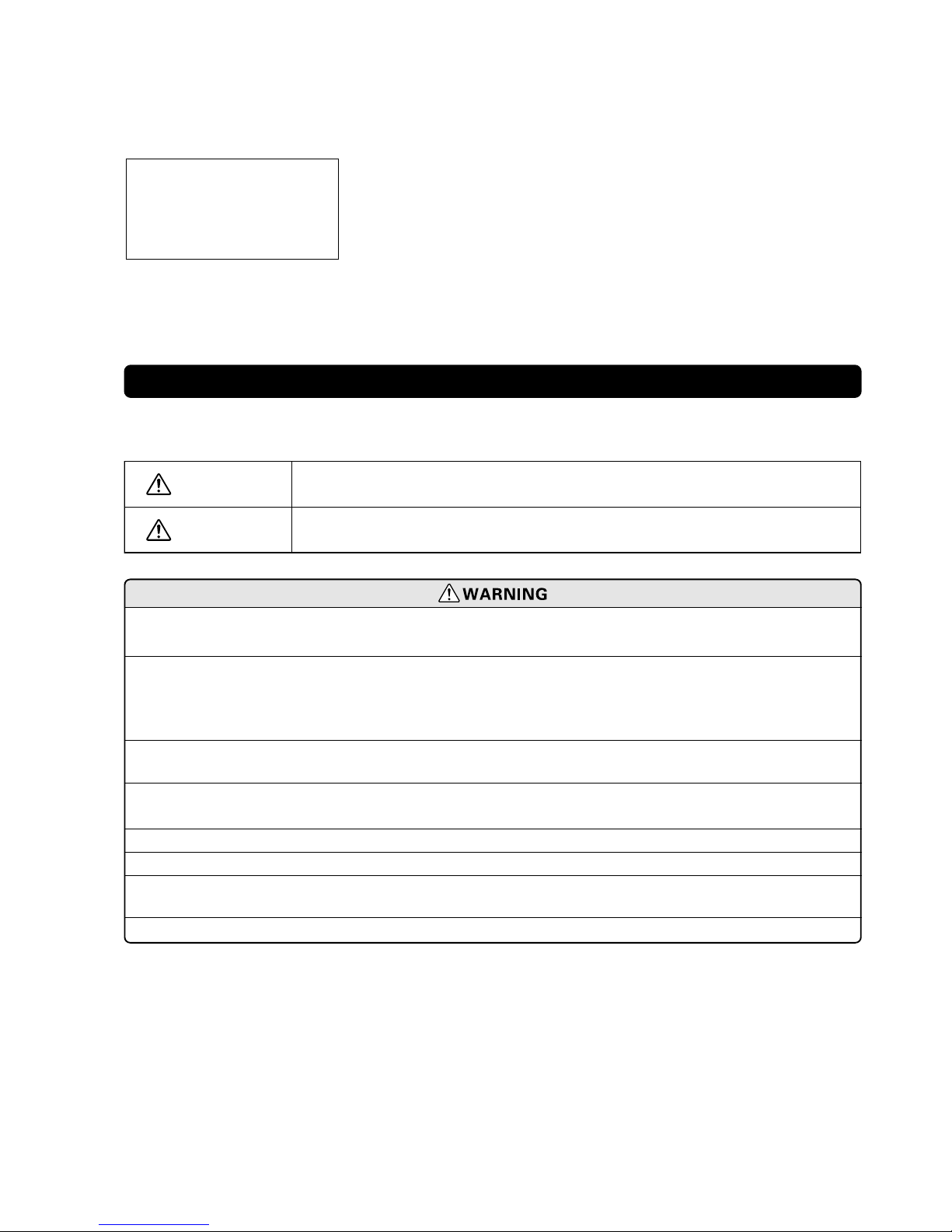
This mark indicates procedures which, if improperly performed, might lead to the
death or serious injury of the user.
This mark indicates procedures which, if improperly performed, might possibly result
in personal harm to the user, or damage to property.
WARNING!
CAUTION!
Refrigerant
R407C
Page 2

SELECTING THE MOUNTING POSITION
– 2 –
(1) Do not install where there is the
danger of combustible gas leakage.
(2) Do not install the unit near a source
of heat, steam, or flammable gas.
(3) If children under 10 years old may
approach the unit, take preventive
measures so that they cannot reach
the unit.
Install at a place that can withstand the
weight of the indoor and outdoor units
and install positively so that the units
will not topple or fall.
Decide the mounting position with the customer as
follows:
INDOOR UNIT
(1) Install the indoor unit level on a strong wall, floor,
ceiling which is not subject to vibration.
(2) The inlet and outlet ports should not be obstructed :
the air should be able to blow all over the room.
(3) Install the unit near an electric outlet or special
branch circuit.
(4) Do not install the unit where it will be exposed to
direct sunlight.
(5) Install the unit where connection to the outdoor unit
is easy.
(6) Install the unit where the drain pipe can be easily
installed.
(7) Take servicing, etc. into consideration and leave the
spaces shown in Fig.1. Also install the unit where
the filter can be removed.
Fig. 1
Left Right
12" (30 cm)
or more
12" (30 cm)
or more
• Floor console
Ceiling
Left
Indoor unit
Right
• Under ceiling
6" (15 cm)
or more
12" (30 cm)
or more
Ceiling
3/4" (2 cm)
or more
Page 3
– 3 –
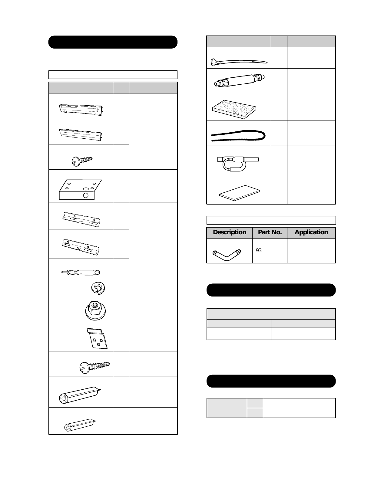
Description Q’ty Application
STANDARD PARTS
CONNECTION PIPE REQUIREMENT
The following installation parts are furnished.
Use them as required.
1
1
2
1
1
4
4
4
2
6
1
1
Cover plate (left)
Cover plate (right)
Tapping screw (ø4 x 10)
Bracket (left)
Bracket (right)
Installation template
For suspending
the indoor unit
from ceiling
Name and Shape Q’ty Application
1
1
1
1
1
2
1
For positioning
the indoor unit
For under ceiling
type
INDOOR UNIT ACCESSORIES
OPTIONAL PARTS FOR INDOOR UNIT
Anchor bolt (M12)
Spring washer
Special nut
Wall bracket
For suspending
the indoor unit on
the wall
Tapping screw
(ø4 x 20)
For fixing the wall
bracket
Table 1
ELECTRICAL REQUIREMENT
Table 2
Diameter
2.5
1.5
MAX
MIN
Connection
cord (mm
2
)
Small Large
9.53 mm 15.88 mm
• Use 0.7 mm to 1.2 mm thick pipe.
• Use pipe with water-resistant heat insulation.
• Use pipe that can withstand a pressure of 3,040 kPa.
• Always use H07RN-F or equivalent as the connection cord.
• Install the disconnection device with a contact gap
of at least 3 mm nearby the units. (Both indoor unit
and outdoor unit)
Coupler heat insulation
(large)
Coupler heat insulation
(small)
For indoor side
pipe joint
(large pipe)
For indoor side
pipe joint
(small pipe)
Nylon fastener
Drain hose
For fixing the
drain hose
Insulation (drain hose)
Adhesive type
70 x 230
VT wire
For fixing the drain
hose L 280 mm
Indoor capillary tube
BR sheet
65 x 130 x T5
Description Part No. Application
9302812021
Joint pipe-A
For indoor side
pipe joint
Page 4
1.
PREPARING INDOOR UNIT INSTALLATION
2. INDOOR UNIT INSTALLATION
INSTALLATION PROCEDURE
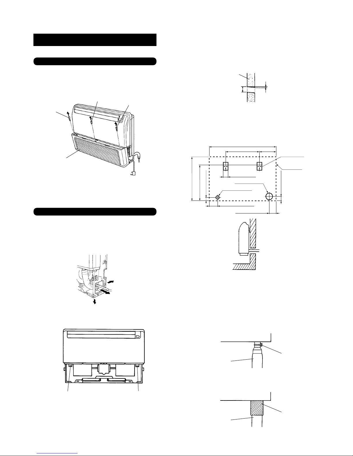
REMOVE THE INTAKE GRILLE
Open the intake grille and remove the three screws
(Fig. 2).
Remark : The main unit can be wired before the
indoor unit is installed. Select the most
appropriate installation order.
Install the air conditioner as follows:
Fig. 2
Tapping screw
Machine screw
Tapping screw
Intake grille
Fig. 3
Fig. 4
Drain hose
(left side)
Drain hose
(right side)
A. FLOOR CONSOLE TYPE
1. DRILLING FOR PIPING
Select piping and drain directions (Fig. 3).
The piping and drain can be made in three directions
as shown below.
The drain hose can be connected to either the left or
right side (Fig. 4).
2. INSTALLING DRAIN HOSE
INSTALL THE DRAIN HOSE
Select whether the drain hose will be connected to the
left or right side (Fig. 4).
Insert the drain hose into the drain pan, then secure
the drain hose with a nylon fastener (Fig. 7).
Wrap the insulation (drain hose) around the drain
hose connection (Fig. 8).
Fig. 7
Drain pan
Nylon fastener
Drain hose
Fig. 6
– 4 –
Fig. 5
Wall
4" (100 mm)
When the directions are selected, drill a 4” (10 cm) dia.
hole on the wall so that the hole is tilted downward
toward the outdoor for smooth water flow. When the
pipe is led out from the rear, make a hole in Fig. 5, at
the position shown.
When installing set to wall install the accessory wall
bracket at the position shown in Fig. 6, and mount the
set to it.
Indoor side
1/4" (6 mm)
Outdoor side
4" (10 cm) hole
2" (5 cm) hole
5" (12.5 cm) hole
4" (10 cm) hole
26" (65.5 cm)
21" (53 cm)
1-3/4" (4.5 cm)
2-1/2" (6.5 cm)
20" (50 cm)
39" (99 cm)
2-1/2" (6.5 cm)
9-5/8"
(24.5 cm)
Wall bracket
Side of set
Fig. 8
Drain pan
Insulation
(drain hose)
Drain hose
Page 5

– 5 –
Do not install the unit so that the drain
hose side is too high. Height A should be
less than 5 mm (Fig. 10).
Be sure to arrange the drain hose so that it is leveled
lower than the drain hose connecting port of the
indoor unit.
Fig. 9
OK
NO
NO
Drain hose
Arrange the drain hose
lower than this portion
Fig. 10
Drain hose
A
A
BAD
BAD
When the directions are selected, drill 3-1/8” (80 mm)
and 2” (50 mm) or 6” (150 mm) dia. hole on the wall
so that the hole is tilted downward toward the outdoor
for smooth water flow.
Fig.11
35.4" (900 mm)
7-7/8"
(200 mm)
Installation
template
Install the drain hose at the rear; it
should not be installed on the top or
right side.
B. UNDER CEILING TYPE
Using the installation template, drill holes for piping
and anchor bolts (for holes) (Fig. 11).
2. DRILLING HOLES FOR ANCHOR BOLTS AND
INSTALLING THE ANCHOR BOLTS
With a concrete drill, drill four 1/2” (12.7 mm) dia.
holes (Fig. 14).
Insert the anchor bolts into the drilled holes, and drive
the pins completely into the anchor bolts with a
hammer (Fig. 15).
1. DRILLING FOR PIPING
Select piping and drain directions (Fig. 12).
Drilling position
for anchor bolt
Ceiling
Wall
Drilling position
for piping
Fig.13
Wall
1/4" (6 mm)
Indoor side
Outdoor side
Fig.14
ø1/2" (12.7 mm)
2-3/8" to 2-3/4"
(60 to 70 mm)
Fig.15
Fig.12
Top
Rear
(Install the drain hose
in this direction.)
Right
Page 6
– 6 –
3. CONNECTING THE PIPING
(1) Do not use mineral oil on flared part.
Prevent mineral oil from getting into
the system as this would reduce the
lifetime of the units.
(2)
Never use piping which has been used
for previous installations. Only use parts
which are delivered with the unit.
(3)
While welding the pipes, be sure to
blow dry nitrogen gas through them.
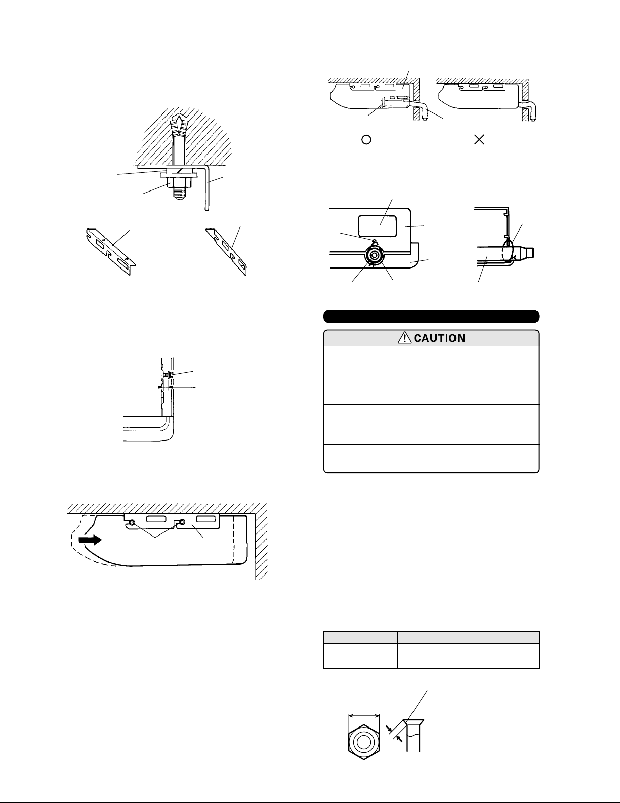
3. INSTALLING BRACKETS
Install the brackets with nuts, washers and spring
washers (Fig. 16).
When drain hose is arranged backward.
Secure the drain hose with the VT wire (Fig.20).
Fig.16
Spring washer
Special nut
Bracket
Bracket (Left)
Bracket (Right)
Fig. 19
Remove the hole cover.
Drain hoseArrange the drain hose
lower than this portion.
OK
NO
Fig.20
Piping hole
Base (Bottom)
VT wire
hole
Intake
grille
VT wire
4. INSTALLING INDOOR UNIT
Reset the hex bolts as shown in Fig. 17.
5. INSTALL THE DRAIN HOSE
Select whether the drain hose will be connected to the
left or right side (Fig. 4).
Insert the drain hose into the drain pan, then secure
the drain hose with a nylon fastener (Fig. 7).
Wrap the insulation (drain hose) around the drain
hose connection (Fig. 8).
Be sure to arrange the drain hose so that it is leveled
lower than the drain hose connecting port of the
indoor unit (Fig. 19).
Apply the indoor unit to the brackets (Fig. 18).
Now, securely tighten the hex bolts in both sides.
Fig.17
Indoor unit
Hex bolt
5/16" to 1/2"
(8 to 1 3mm)
Fig.18
Bolt
Bracket
Indoor unit
Cut the grille
Drain hose
Pass the drain hose
through here.
L
Fig. 21
Width across flats
1. FLARE PROCESSING
(1) Cut the connection pipe with pipe cutters so that the
pipe is not deformed.
(2) Hold the pipe downwards so that cuttings cannot
enter the pipe, remove the burrs.
(3) Remove the flare nut from the indoor unit pipe and
outdoor unit and assemble as shown in (Table 3)
and insert the flare nut onto the pipe, and flare with
a flaring tool.
(4) Check if the flared part “L” (Fig. 21) is spread
uniformly and that there are no cracks.
Pipe Flare nut
Small pipe Small (width across flats 22 mm)
Large pipe Large (width across flats 24 mm)
Table 3
L dimension
Small pipe
1 .8 to 2.0mm (9.53mm dia.)
Large pipe
2.2 to 2.4mm (15.88mm dia.)
Page 7
– 7 –
Fig. 24
Indoor unit side
Optional parts
2. BENDING PIPES
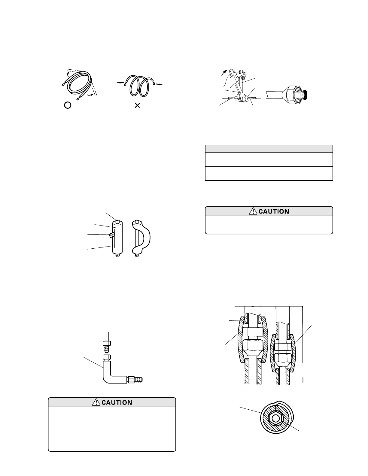
The pipes are shaped by your hands. Be careful not to
collapse them.
3. CONNECTION PIPES
Centering the pipe against port on the indoor unit,
turn the flare nut with your hand (Fig. 24).
Be sure that the small pipe is completely installed
before connecting the large pipe.
Do not bend the pipes in an angle more than 90°.
When pipes are repeatedly bent or stretched, the
material will harden, making it difficult to bend or
stretch them any more. Do not bend or stretch the
pipes more than three times.
When bending the pipe, do not bend it as is. The pipe
will be collapsed. In this case, cut the heat insulating
pipe with a sharp cutter as shown in Fig. 23, and bend
it after exposing the pipe. After bending the pipe as
you want, be sure to put the heat insulating pipe back
on the pipe, and secure it with tape.
Be sure to apply the pipe against the
port on the indoor unit correctly. If the
centering is improper, the flare nut
cannot be tightened smoothly. If the flare
nut is forced to turn, the threads will be
damaged.
Fig. 25
Tighten with two wrenches.
Wrench (fixed)
Flare nut
Torque
wrench
When the flare nut is tightened properly by your hand,
use a torque wrench to finally tighten it.
Indoor unit
pipe
Connection pipe
To prevent gas leakage,
coat the flare surface with
refrigerator oil.
Do not remove the cap from the connection pipe
before connecting the pipe.
Be sure to connect the large pipe after
connecting the small pipe completely .
Fig.26
Indoor unit
No gap
Coupler heat
insulation
(small)
Be sure to
overlap the
insulation
Large pipe
4. HEAT INSULATION ON THE PIPE JOINTS
(INDOOR SIDE ONLY)
Put coupler heat insulation on the joints (indoor side
only) (Fig. 26).
Small pipe
Coupler heat
insulation (large)
Coupler heat insulation
Flare nut Tightening torque
Small pipe
30.4 to 34.3 N
•
m
9.53 mm dia.
(310 to 350 kgf
•
cm)
Large pipe
73.6 to 78.5 N •m
15.88 mm dia.
(750 to 800 kgf
•
cm)
Table 4 : Flare nut tightening torque
No gap
}
Fig. 22
Extend the pipe
by unwinding it.
OK
NO
Fig. 23
Pipe
Heat insulating
pipe
Cutter
Cut line
Page 8
– 8 –
5.
HOW TO CONNECT WIRING TO THE TERMINALS
Fig. 31
A. Solid wire B. Strand wire
Loop
Insulation
Strip 15/16”
(25 mm)
Strip 3/8”
(10 mm)
Screw with
special washer
1. IF ONE WIRE IS CONNECTED TO ONE
TERMINAL BLOCK.
A.For solid core wiring (or F-cable)
(1) Cut the wire end with a wire cutter or wire-
cutting pliers, then strip the insulation to about
15/16” (25 mm) to expose the solid wire.
(2) Using a screwdriver, remove the terminal
screw(s) on the terminal board.
(3) Using pliers, bend the solid wire to form a loop
suitable for the terminal screw.
(4) Shape the loop wire properly, place it on the
terminal board and tighten securely with the
terminal screw using a screwdriver.
B.For strand wiring
(1) Cut the wire end with a wire cutter or wire-
cutting pliers, then strip the insulation to about
3/8” (10 mm) to expose the strand wiring.
(2) Using a screwdriver, remove the terminal
screw(s) on the terminal board.
(3) Using a round terminal fastener or pliers,
securely clamp a round terminal to each stripped
wire end.
(4) Position the round terminal wire, and replace
and tighten the terminal screw using a screwdriver.
Round
terminal
Terminal
board
Round
terminal
Screw with
special washer
Round terminal
Wire
Wire
Terminal block
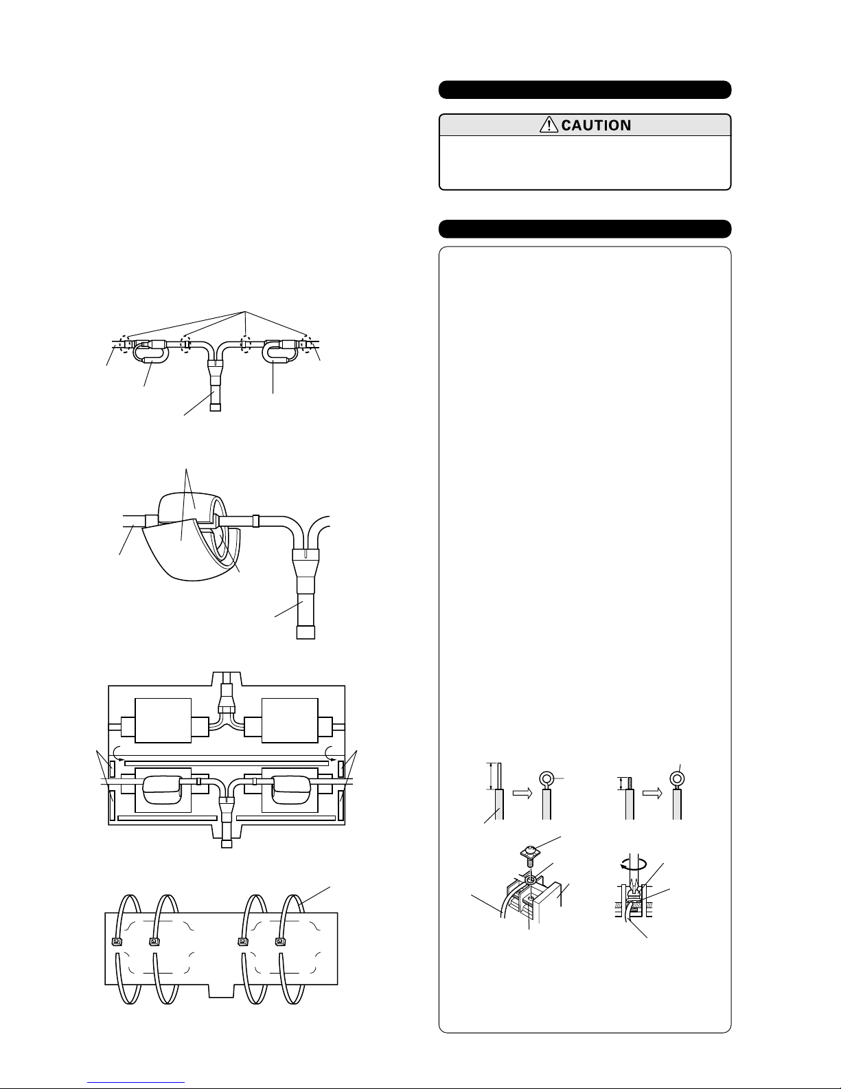
5. CONNECTING AN INDOOR CAPILLARY TUBE
Installation Procedure
(1) Braze each part (connection pipe, indoor capillary
tube, and branch liquid pipe) as shown in Fig. 27.
(2) Wrap the two BR sheets around the indoor capillary
tube as shown in Fig. 28.
(3) Cover the indoor capillary tube and the branch
liquid pipe with insulation (Fig. 29) and affix the
insulation with tape.
(4) Secure the insulation using the binders (Fig. 30).
• If the joint pipe must be installed, refer to the
installation installation manual for the outdoor unit
for details.
Fig. 27
Connection
pipe
Connection
pipe
Branch liquid pipe
Indoor unit
side
Indoor unit
side
Outdoor unit side
Indoor capillary
tube
Indoor
capillary tube
Brazing (all around)
Fig. 28
BR sheet
Connection pipe
Branch liquid pipe
Indoor
capillary tube
Fig. 29
Tape
Tape
Fig. 30
Binder
After connecting the piping, check the
joints for gas leakage with gas leak
detector .
4. GAS LEAKAGE INSPECTION
Page 9
– 9 –
6. ELECTRICAL WIRING
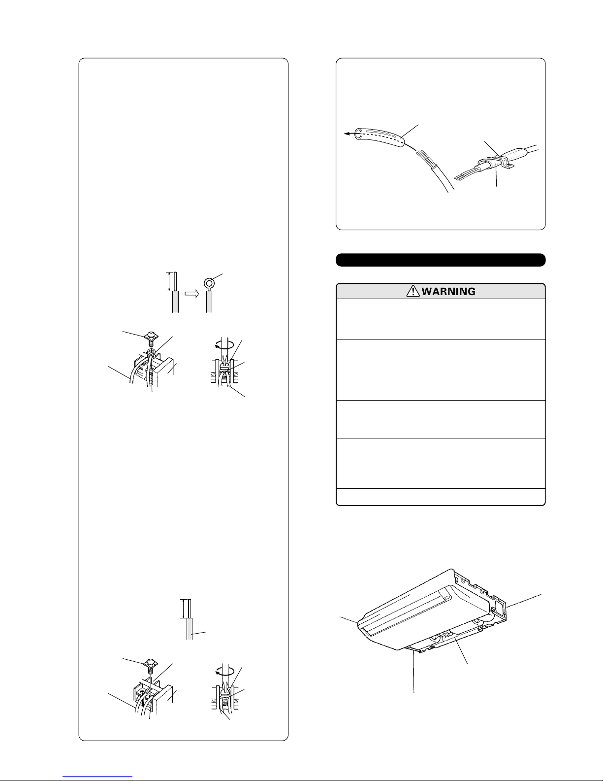
B.If round terminal cannot be used, the
following items should be followed.
For solid core wiring (or F-cable)
(1) Cut the wire end with a wire cutter or wire-
cutting pliers, then strip the insulation to about
1/2” (12.7 mm) to expose the solid wire.
(2) Using a screwdriver, remove the terminal
screw(s) on the terminal board.
(3) Wires with the same diameter should be
connected on both sides as shown in Fig. 33.
Since connecting wires with different diameters
causes the wires to heat up due to loose
connections, this method should not be used.
HOW TO FIX THE CONNECTION CORD
After passing the connection cord through the
insulation tube, fasten it with the cord clamp.
Use VW-1, 0.5 to 1.0 mm thick, PVC tube as the
insulation tube.
Fig. 34
Insulation tube
Insulation tube
Cord clamp
(1) Before starting work, check that
power is not being supplied to the
indoor unit.
(2) Match the terminal board numbers
and connection cord colors with
those of the indoor unit.
Erroneous wiring may cause burning
of the electric parts.
(3) Connect the connection cord firmly
to the terminal board. Imperfect
installation may cause a fire.
(4) Always fasten the outside covering
of the connection cord with the cord
clamp. (If the insulation is chafed,
electric leakage may occur.)
(5) Always connect the ground wire.
2. IF TWO WIRES ARE CONNECTED TO
ONE TERMINAL BLOCK.
A.As a rule, round terminal should be used
to connect to the terminal block.
(1) Cut the wire end with a wire cutter or wire-
cutting pliers, then strip the insulation to about
3/8” (10 mm) to expose the strand wiring.
(2) Using a screwdriver, remove the terminal
screw(s) on the terminal board.
(3) Using a round terminal fastener or pliers,
securely clamp a round terminal to each stripped
wire end.
(4) Position the round terminal wire, and replace
and tighten the terminal screw using a screwdriver.
1.
REMOVE THE ELECTRIC COMPONENT BOX
Fig.35
Electric component box
Fig. 32
Strip 3/8”
(10 mm)
Screw with
special washer
Round
terminal
Terminal
board
Round
terminal
Screw with
special washer
Round terminal
Wire
Wire
Terminal block
Strand wire
Fig. 33
Strip 1/2”
(12.7 mm)
Screw with
special washer
Round
terminal
Terminal
board
Round
terminal
Screw with
special washer
Insulation
Wire
Wire
Terminal block
Solid wire
Page 10
– 10 –
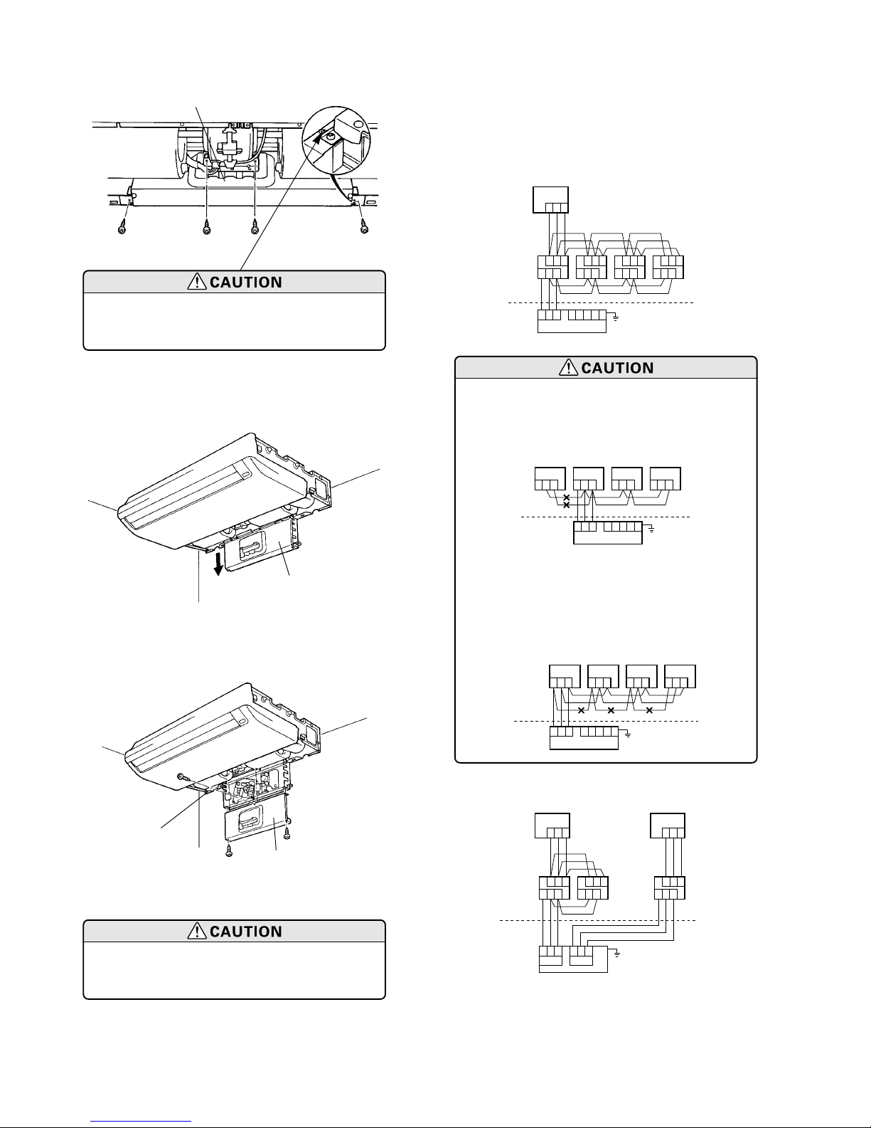
4. WIRING
A. Simultaneous operation for buildings
Remote
controller
Indoor
unit
Outdoor
unit
MasterRSlave Slave Slave
qwe
qwe qwe qwe qwe
qwe qweqweqwe
qwe
STNE
The Earth wire is omitted.
Fig. 39
B. Individual operation for buildings
Remote
controller
Indoor
unit
Outdoor
unit
Master Master
A
Slave
qweBqwe
qwe qwe qwe
qwe qwe
Remote
controller
qwe qwe qwe
The Earth wire is omitted.
Fig. 42
(1) Connect a maximum of 2 wires on a
single terminal block. (If 3 or more
wires are connected, they could
become loose and cause heating.)
(2) Crossovers as in (q should not be
connected when connecting wires
between the master unit and slave
units, and from slave unit to slave
unit. (The system will not operate
correctly.)
Indoor unit
Outdoor
unit
Master
R
Slave Slave Slave
qwe
qwe
qwe qwe qwe
STNE
BAD
Fig. 40
Indoor unit
Outdoor
unit
MasterRSlave Slave Slave
qwe
qwe
qwe qwe qwe
STNE
BAD BAD BAD
Fig. 41
Do not remove the screws. If the stays
are removed, the electric component box
will fall.
2.
PULL OUT THE ELECTRIC COMPONENT BOX
Fig.37
Electric component box
Fig. 36
Electric component box
Remove the four
tapping screws.
Fig.38
Electric component box
3. REMOVE THE ELECTRIC COMPONENT
BOX COVER
Remove the three tapping screws.
Base
Be careful not to pinch the lead wires
between the electric component box and
base.
Page 11
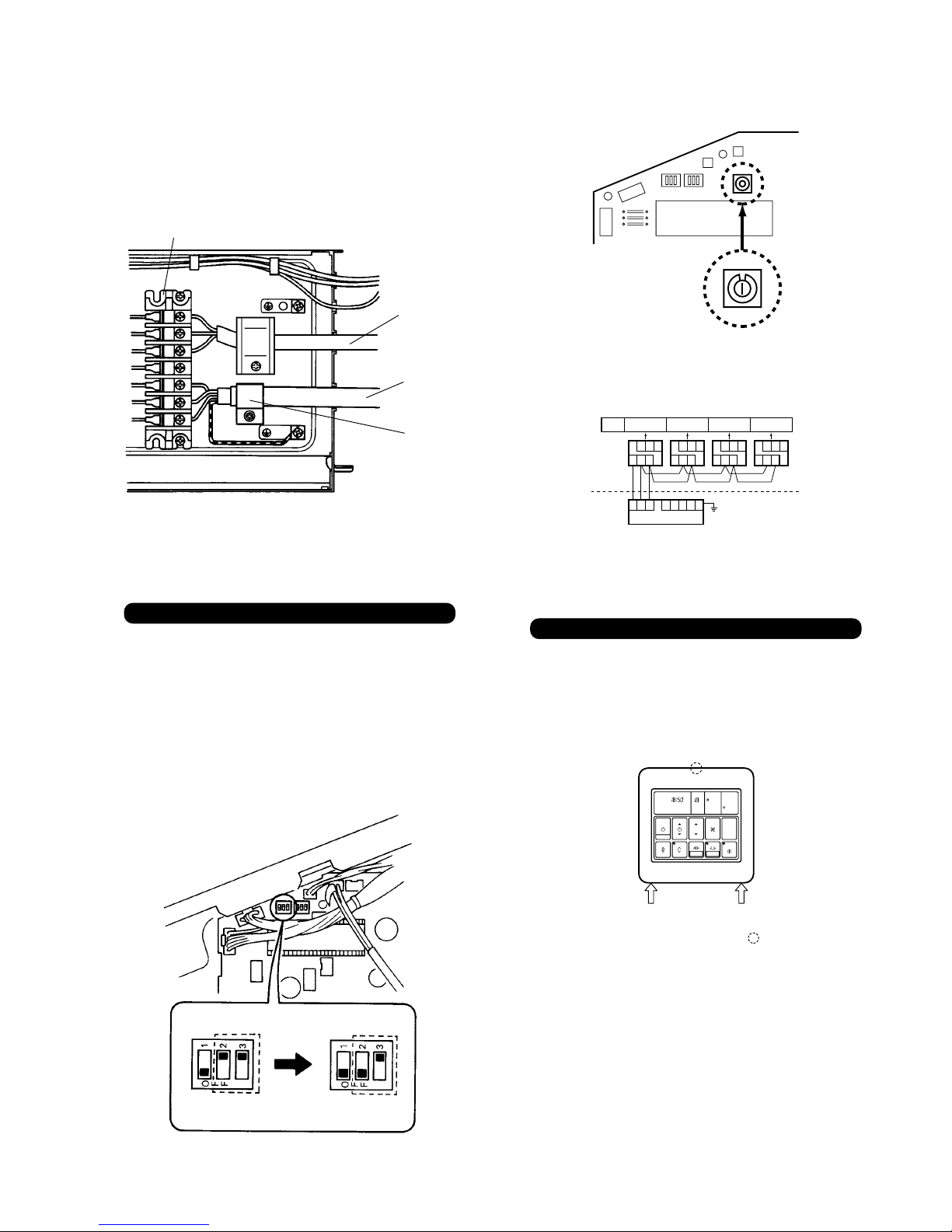
1. FLOOR CONSOLE / UNDER CEILING
SELECT SWITCH
– 11 –
7. PRINTED CIRCUIT BOARD SETTING
2. MASTER/SLAVE SELECT SWITCH
0
SW2
Fig. 45
Indoor unit
Printed circuit board
• For the master unit, set SW2 on ”0”. For a slave
unit, set SW2 on ”1~3”.
• A master unit is an indoor unit with the power line
connected directly from the outdoor unit.
Indoor
unit
SW20123
Outdoor
unit
MasterRSlave Slave Slave
qwe
qwe qwe qwe qwe
qwe qwe qwe qwe
STNE
Fig. 46 [Example]
8. REMOTE CONTROLLER INSTALLATION
• Insert the end of a flat blade screwdriver at the
arrow parts of the groove at the side of the remote
controller case and remove the remote controller
case top by turning the screwdriver.
• Disconnect the remote controller cord from the
remote controller terminal board.
(1) When remote controller exposed
1) Make a notch in the thin part ( part of Fig. 47) at
the remote controller case top and bottom with
nippers, file, etc.
2) Connect the remote controller cord to the remote
controller terminal board specified in (Fig. 48).
3) Clamp the remote controller cord sheath with the
binder (small) as shown in Fig. 48.
4) Cut off the excess binder.
°C
NON STOP
CLOCK
TEMP
AUTO
TIMER
MODE
SET
START/STOP
CLOCK ADJUST
SET TIME TEMP./DAY FAN
CONTROL
MASTER
CONTROL
21
HIGH
COOL
DEFROST TEST
DAY OFF
Fig. 47
Fig. 43
Terminal board
Connection
cord
Cord clamp
Remote
controller cord
(4) Fasten the connection cord with a cord clamp.
(5) Fasten the end of the connection cord with the
screw.
(1) The electrical circuits for this were set for use as a
ceiling type at the factory.
(2) The following changes must be made to the
settings if the unit is to be used as a floor type.
(3) Changing the settings for the electrical circuits.
Switch 1 (SW1) on the printed circuit board inside
the electric component box must be set as follows.
(1) Remove the cord clamp.
(2) Process the end of the connection cords to the
dimensions shown in Fig. 43.
(3) Connect the end of the connection cord fully into the
terminal board.
Fig. 44
Microcomputer
SW1
SW1
SW1
Under ceiling type
Floor console type
Page 12
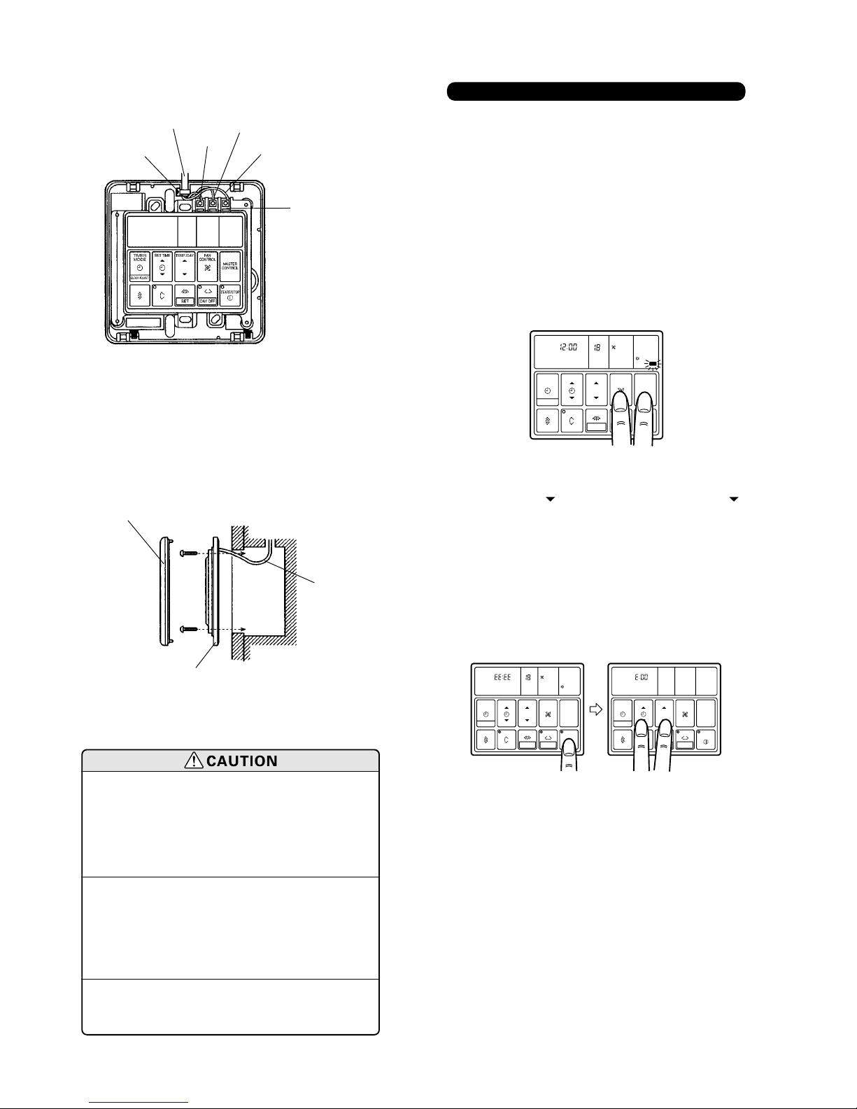
9. TEST RUNNING
REMOTE CONTROLLER
• Supply power to the crankcase heater 12 hours
before the start of operation in the winter.
• For test running, when the remote controller FAN
CONTROL button and MASTER CONTROL button
are pressed simultaneously for more than three
seconds when the air conditioner is not running, the
air conditioner starts and TEST is displayed on the
remote controller display.
However, the SET TEMP./DAY setting button does
not function, but all other buttons, displays, and
protection functions operate (Fig. 50).
• When EE : EE blinks at the current time display,
there is an error inside the air conditioner. If the SET
TIME button ( ) and SET TEMP./DAY button ( )
are pressed simultaneously for more than three
seconds, the self diagnosis check will start and the
error contents will be displayed at the current time
display (Fig. 51). When the operation lamp lights,
press the START/STOP button and after operation
lamp goes off, perform the same operation (Fig. 51).
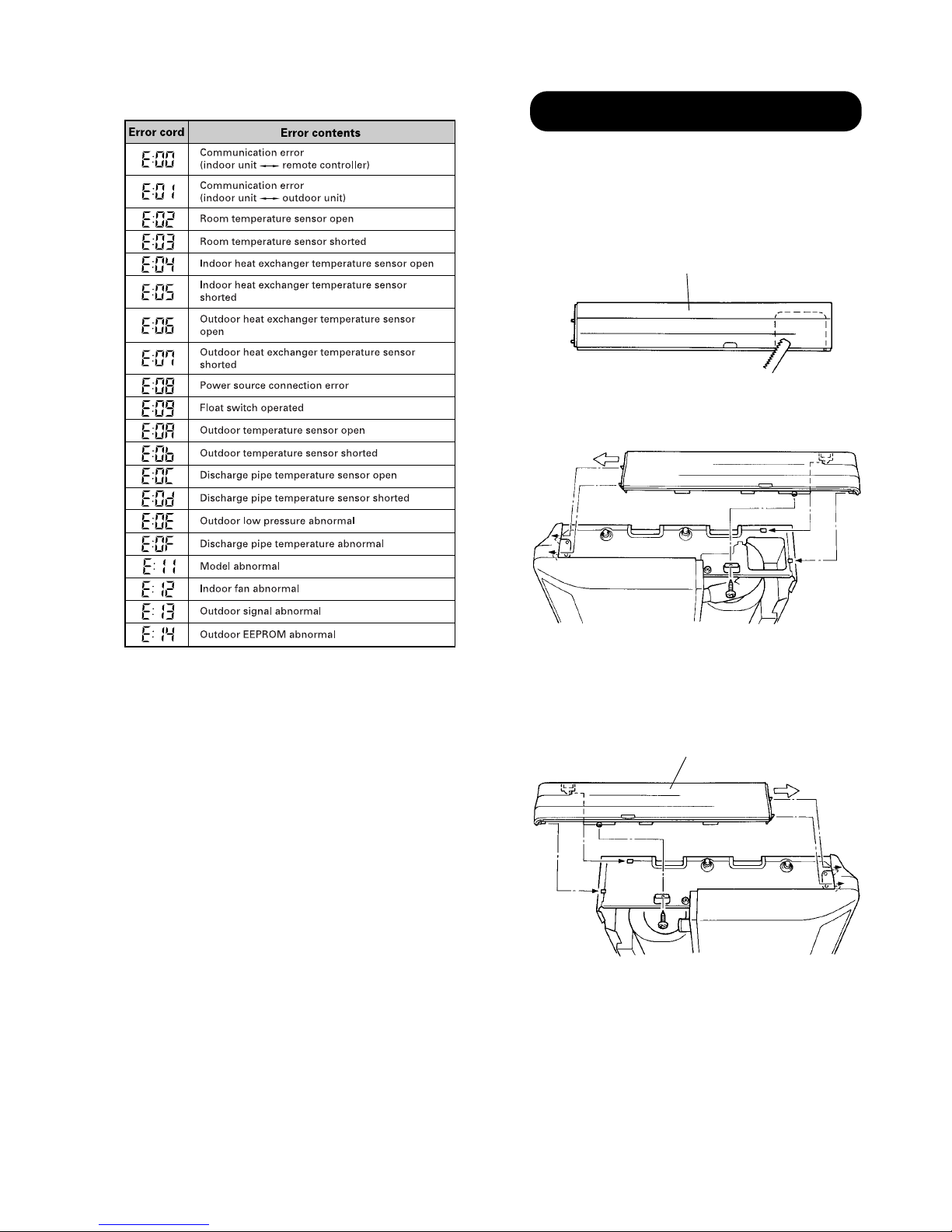
Process the error contents by referring to (Table 5).
°C
NON STOP
CLOCK
TEMP
AUTO
TIMER
MODE
SET
START/STOP
CLOCK ADJUST
SET TIME TEMP./DAY FAN
CONTROL
MASTER
CONTROL
21
HIGH
COOL
DEFROST TEST
DAY OFF
Fig. 50
°C
NON STOP
CLOCK
TEMP
AUTO
TIMER
MODE
SET
START/STOP
CLOCK ADJUST
SET TIME TEMP./DAY FAN
CONTROL
MASTER
CONTROL
21
HIGH
COOL
DEFROST
DAY OFF
AUTO
TIMER
MODE
SET
START/STOP
CLOCK ADJUST
SET TIME TEMP./DAY FAN
CONTROL
MASTER
CONTROL
21
DAY OFF
Fig. 51
– 12 –
Fig. 48
(2) When remote controller cord embedded
1) Embed the remote controller cord and box.
2) Pass the remote controller cord through the hole
at the remote controller case bottom and install
the cord to the box (Fig. 49).
3) Connect the remote controller cord to the remote
controller terminal board specified in (Fig. 48).
Remote controller
terminal board
Black
Red
White
Remote
controller cord
Binder (small)
• After wiring work is complete, return the remote
controller case top to its original state.
Fig. 49 [Example]
Remote controller
case bottom
Remote
controller cord
Remote controller
case top
(1) Do not bundle the remote controller
cord, or wire the remote controller
cord in parallel, with the indoor unit
connection wire (to the outdoor
unit) and the power supply cord. It
may cause erroneous operation.
(2) When installing the remote con-
troller and cord near a source of
electromagnetic waves, separate the
remote controller from the source of
the electromagnetic waves and use
shielded cord.
(3) Do not touch the remote controller
PC board and PC board parts directly
with your hands.
Stop operation
Page 13
• To stop test running, press the START/STOP button.
• For the operation method, refer to the operating
manual and perform operation check.
• Check that there are no abnormal sounds or
vibration sounds during test running.
– 13 –
Table 5
1. MOUNT THE COVER PLATE (RIGHT)
(1) Cut a pipe exit hole in the right plate. This is only
when the pipe exits from the right side. (This
operation is not required when the protrusion is on
the top or rear.)
(2) Join the cover plates (right) and mount with screws
(Fig.53).
10. MOUNT THE COVER PLATE AND
THE INTAKE GRILLE
Fig.52
Cover plate(right)
Fig.53
2. MOUNT THE COVER PLATE (LEFT)
(1) Join the cover plates (left) and mount with screws.
Fig.54
Cover plate (left)
Page 14
– 14 –
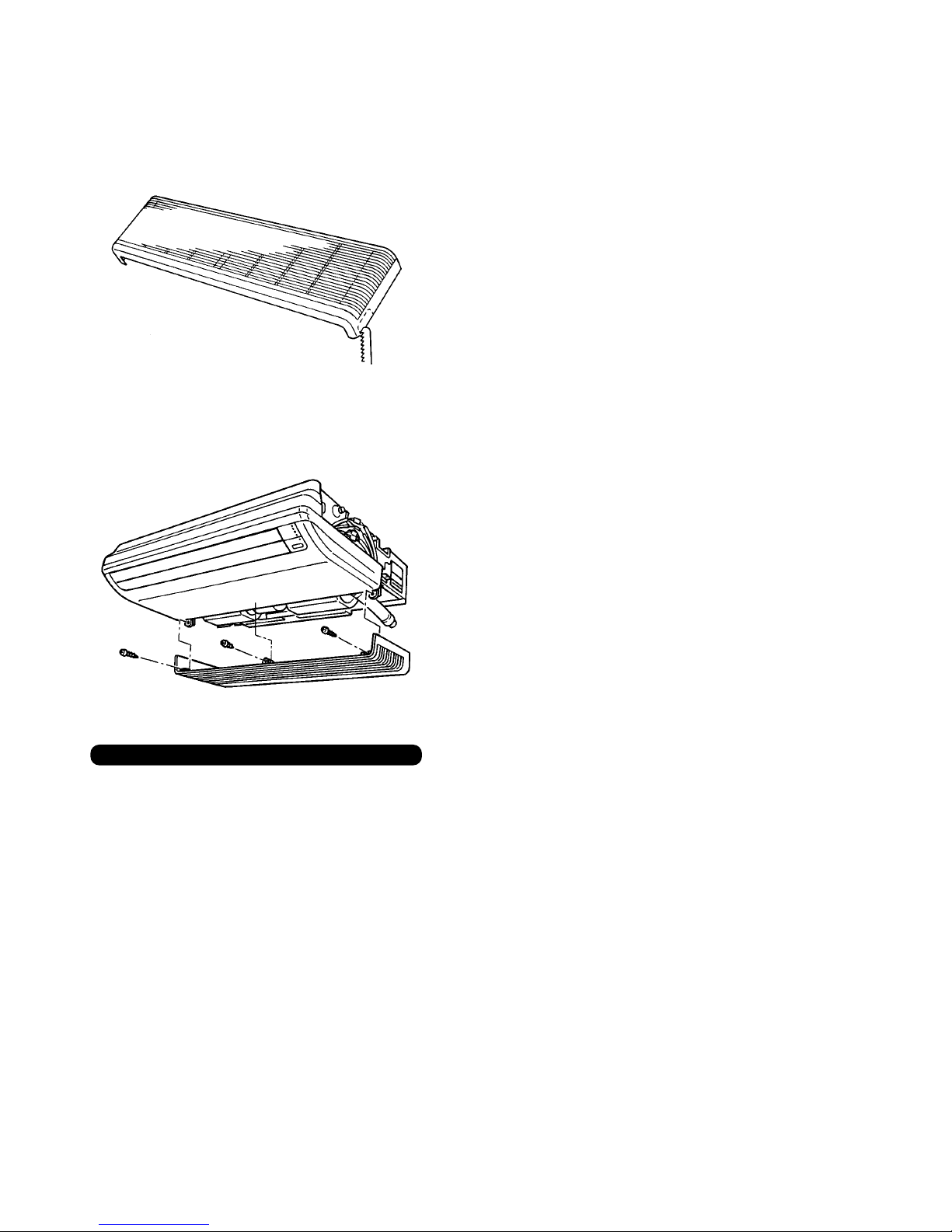
(2) Insert the hinges on the bottom of the intake grille
into the holes in the base assembly. Then mount the
arms to the three areas on the top of the intake grille
(Fig. 56).
Fig.55
Fig.56
3. MOUNT THE INTAKE GRILLE
(1) Cut the right side of the intake grille. This is only
when the pipe exits from the right side (Fig. 55).
Explain the following to the customer in accordance
with the operating manual :
(1) Starting and stopping method, operation switching,
temperature adjustment, timer, air flow switching,
and other remote controller operations.
(2) Air filter removal and cleaning, and how to use the
air louvers.
(3) Give the operating and installation manuals to the
customer.
11. CUSTOMER GUIDANCE
 Loading...