

Miranda Camera Co M406-9900-402, KALEIDO-K2 User Manual

High Resolution
Kaleido-K2
Guide to Installation and Operation
M406-9900-402
Copyright 2006 Miranda Technologies Inc.
Specifications may be subject to change.
Printed in Canada
November 2006
Virtual Monitor
Wall Processor
Miranda
Technologies inc.
3499 Douglas-B. Floreani
St-Laurent, Québec, Canada H4S 1Y6
Tel. 514-333-1772
Fax. 514-333-9828
www.miranda.com
Kaleido-K2

GUIDE TO INSTALLATION AND OPERATION
Safety Compliance Information
Safety Compliance
This equipment complies with:
- CSA C22.2 No. 60950-1-03 / Safety of Information Technology Equipment, Including Electrical Business Equipment.
- UL 60950-1 (1
- IEC 60950-1 (1
st
Edition) / Safety of Information Technology Equipment, Including Electrical Business Equipment.
st
Edition) / Safety of Information Technology Equipment, Including Electrical Business Equipment.
CAUTION
These servicing instructions are for use by qualified service personnel only. T o reduce the risk of electric shock, do not
perform any servicing other than that contained in the operating instructions unless you are qualified to do so. Refer all
servicing to qualified service personnel. Servicing should be done in a sta tic-free environment.
Electromagnetic Compatibility
- This equipment has been tested for verification of compliance with FCC Part 15, Subpart B, class A requirements for Digital
Devices.
- This equipment complies with the requirements of:
EN 55022 Class A, Electromagnetic Emissions,
EN 61000-3-2 & -3-3, Disturbance in Supply Systems
EN 61000-4-2, -3, -4, -5, -6, -8 & -11 Electromagnetic Immunity
How to contact us:
For technical assistance, please contact the Miranda Technical support centre nearest you:
Americas
Telephone:
+1-800-224-7882
e-mail:
techsupp@miranda.com
Asia
Telephone:
+81-3-5730-2987
e-mail:
asiatech@miranda.com
Europe, Middle East,
Africa, UK
Telephone:
+44 (0) 1491 820222
e-mail:
eurotech@miranda.com
France (only)
Telephone:
+33 (0) 1 55 86 87 88
e-mail:
francetech@miranda.com
Visit our web site at www.miranda.com
Kaleido K2

GUIDE TO INSTALLATION AND OPERATION
Contents
1 Kaleido-K2 High Resolution Virtual Monitor Wall Processor....................................................................1
1.1 Introduction...............................................................................................................................................1
1.2 Features ...................................................................................................................................................1
2 Overview ......................................................................................................................................................3
2.1 Front Panel...............................................................................................................................................3
2.2 Rear Panel ...............................................................................................................................................3
3 Mechanical Installation..................................................................................................................................4
3.1 Unpacking.................................................................................................................................................4
3.2 Rack-mount installation............................................................................................................................4
3.2.1 Installing Kaleido-RCP in a rack using the mounting bracket.......................................................4
4 Frame and electrical installation...................................................................................................................6
4.1 Frame …………........................................................................................................................................6
4.2 Power Supplies.……................................................................................................................................6
4.2.1 Installation.....................................................................................................................................6
4.2.2 Operation ......................................................................................................................................7
4.2.3 Ventilation.....................................................................................................................................7
4.3 Module Installation and replacement .......................................................................................................7
4.3.1 Connector panel installation .........................................................................................................8
4.3.2 Module card installation ................................................................................................................8
4.4 Module description and connection..........................................................................................................9
4.4.1 Controller Module(MWA-CPU) .....................................................................................................9
4.4.2 GPI Module (MWA-GPI) .............................................................................................................12
4.4.3 Analog Audio Input Module (MWI-SA)........................................................................................14
4.4.4 Digital Audio Input Module (MWI-AES).......................................................................................15
4.4.5 Composite Analog Video Input Module (MWI-CVBS) ................................................................15
4.4.6 Y/C Analog Video Input Module (MWI-YC).................................................................................16
4.4.7 Component Analog Video Input Modul e (MWI-CAV).................................................................16
4.4.8 Digital Video SD-SDI Input Module (MWI-SDI)...........................................................................1
4.4.9 Analog Progressive RGBHV Input Module (MWI-VGA).............................................................17
4.4.10 HD-SDI Video Input Module (MWI-HD)......................................................................................18
4.4.11 Output Module (MWO-HR) .........................................................................................................18
4.5 Multiple Kaleido-K2 installation ..............................................................................................................19
4.5.1 Controlling multiple Kaleido-K2 through an ethernet network ....................................................19
4.5.2 Controlling multiple Kaleido-K2 through RS-422........................................................................21
4.5.3 RS-422 serial ID assignment......................................................................................................21
5 Operation……….... .......................................................................................................................................22
5.1 Startup and preparation to use software..................................................................................…………22
5.2 Installation of software.…… ...................................................................................................................22
6 Maintenance..................................................................................................................................................23
6.1 Cleaning the air filter ..............................................................................................................................23
6.2 Replacing a defective power supply.......................................................................................................23
6.3 Replacing a defective fan.......................................................................................................................23
7 Technical Specifications .............................................................................................................................25
7
Kaleido K2

GUIDE TO INSTALLATION AND OPERATION
Kaleido K2
GUIDE TO INSTALLATION AND OPERATION
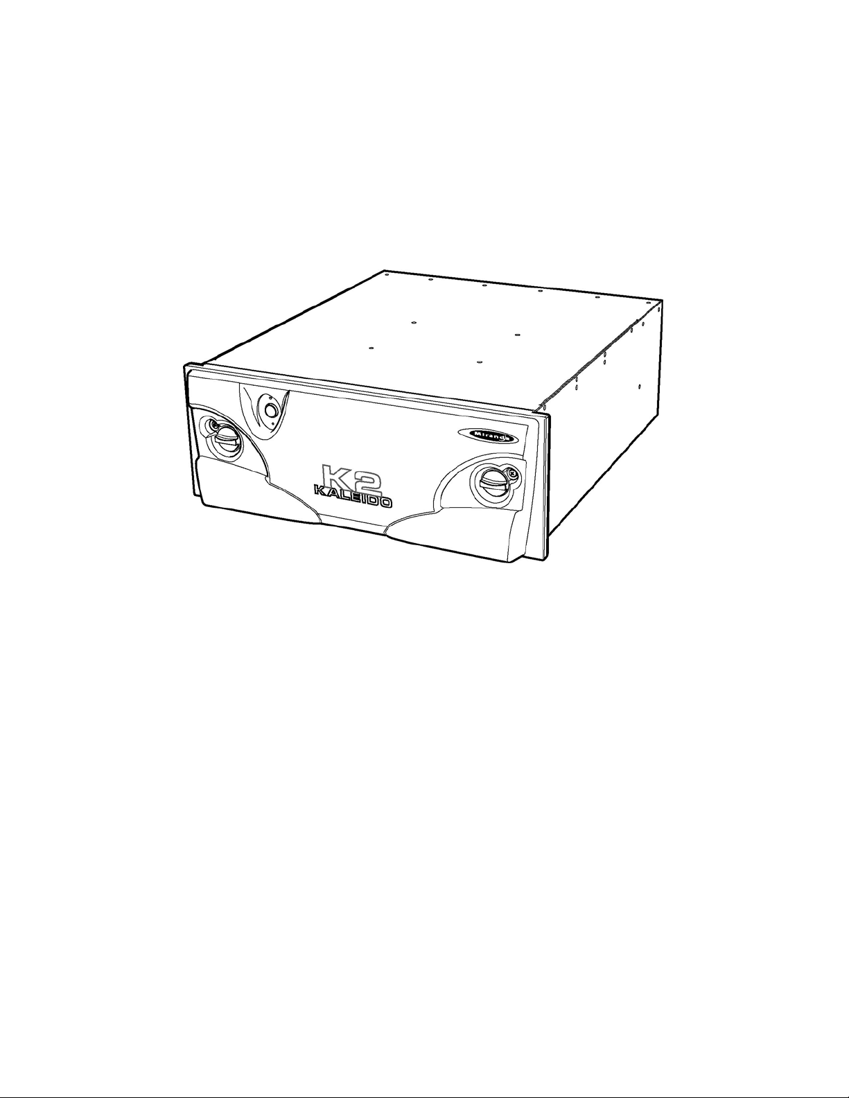
1 Kaleido-K2 Ultra High Resolution Virtual Monitor Wall Processor
1.1 Introduction
The Kaleido-K2 Ultra High Resolution Virtual Monitor Wall Processor is designed as the ultimate solution to signal
monitoring requirements. It accepts inputs in many standard formats; each input is equipped with its own advanced
de-interlacing and scaling engine for highest display quality. Internal processing is handled at 1600x1200 pixel
resolution, and each input can be scaled between 1/16 of its original size and the full 1600x1200 screen. Graphic
elements are keyed with one-pixel precision.
1.2 Features
• High quality processing
• Flexible input configuration
• Audio monitoring
• Daisy-chain capability
• Variable output resolution
• Source IDs
• Clock displays
• Count up/down timer
• Signal status reporting
• Powerful layout editing
• Easy control and configuration
• Reference input (optional)
Kaleido K2 | 1
GUIDE TO INSTALLATION AND OPERATION
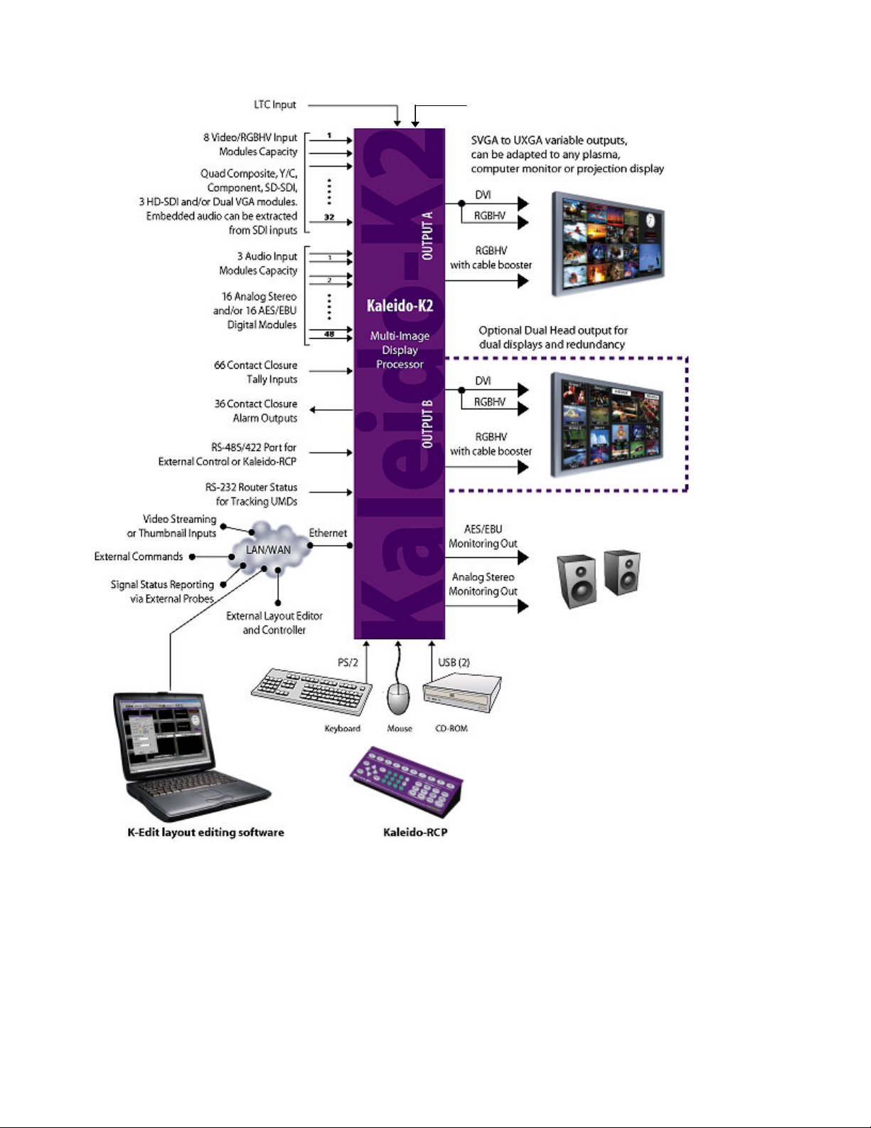
REF Input
Figure 1.2.1 Kaleido-K2 functional block diagram
2 | Kaleido K2
GUIDE TO INSTALLATION AND OPERATION
2 Overview
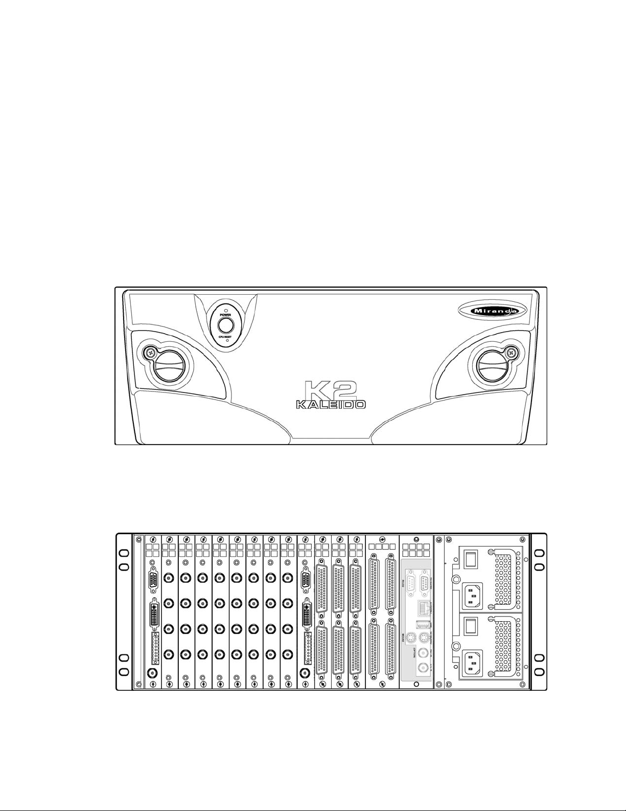
2.1 Front Panel
The front panel of the Kaleido-K2 has three operational elements:
- ON/OFF pushbutton
- System status indicator LED
- CPU reset button.
These items are actually located on the front edge of the controller card. The LED and reset button are accessed
through holes in the panel; the power button on the panel pushes against a smaller button located on the card. The
controller card and the functionality of these controls are described in detail in section 4.4.
There are also knobs which are turned to open the front panel to give access to the card tray and the status LEDs
located on the cards themselves. Each knob is paired with a screw which mu st be removed before the knob can be
turned to open the panel. This provides security against casual access.
2.2 Rear Panel
The rear panel of the Kaleido-K2 incorporates all of the input and output connectors for the installed modules, and
access to the two redundant power supplies. See section 4.4 for a detailed description of the connectors and their
functionality. The power supplies are described in section 4.2.
Kaleido K2 | 3
GUIDE TO INSTALLATION AND OPERATION
3 Mechanical Installation
3.1 Unpacking
Make sure the following items have been shipped with your Kaleido. If any of these are missing, contact your
distributor or Miranda Technologies Inc.
- Kaleido unit, with pre-installed modules and power supplies
- 2 AC power cords
- Kaleido-RCP (remote control panel)
- RS-422 cable
- DVI-A-to-VGA (HD-15) adapter
- red crossover network cable
- Ethernet jack mounted on a keychain
- CD-ROM of system software, release notes and a Quick Start manual.
3.2 Rack-mount installation
Kaleido may be installed in a standard 19” rack, using the proper screws and washers ( not included). The KaleidoRCP Remote Control Panel may also be installed in a rack using the optional mounting kit (order part #1229-110 0-
100).
For proper ventilation, make sure the front and rear panel air vents are not blocked and the air filter is clean.
3.2.1 Installing Kaleido-RCP in a rack using the mounting bracket.
The Kaleido-RCP is designed to be used on a tabletop; however, a mounting kit is available for installation in a
standard 19” equipment rack.
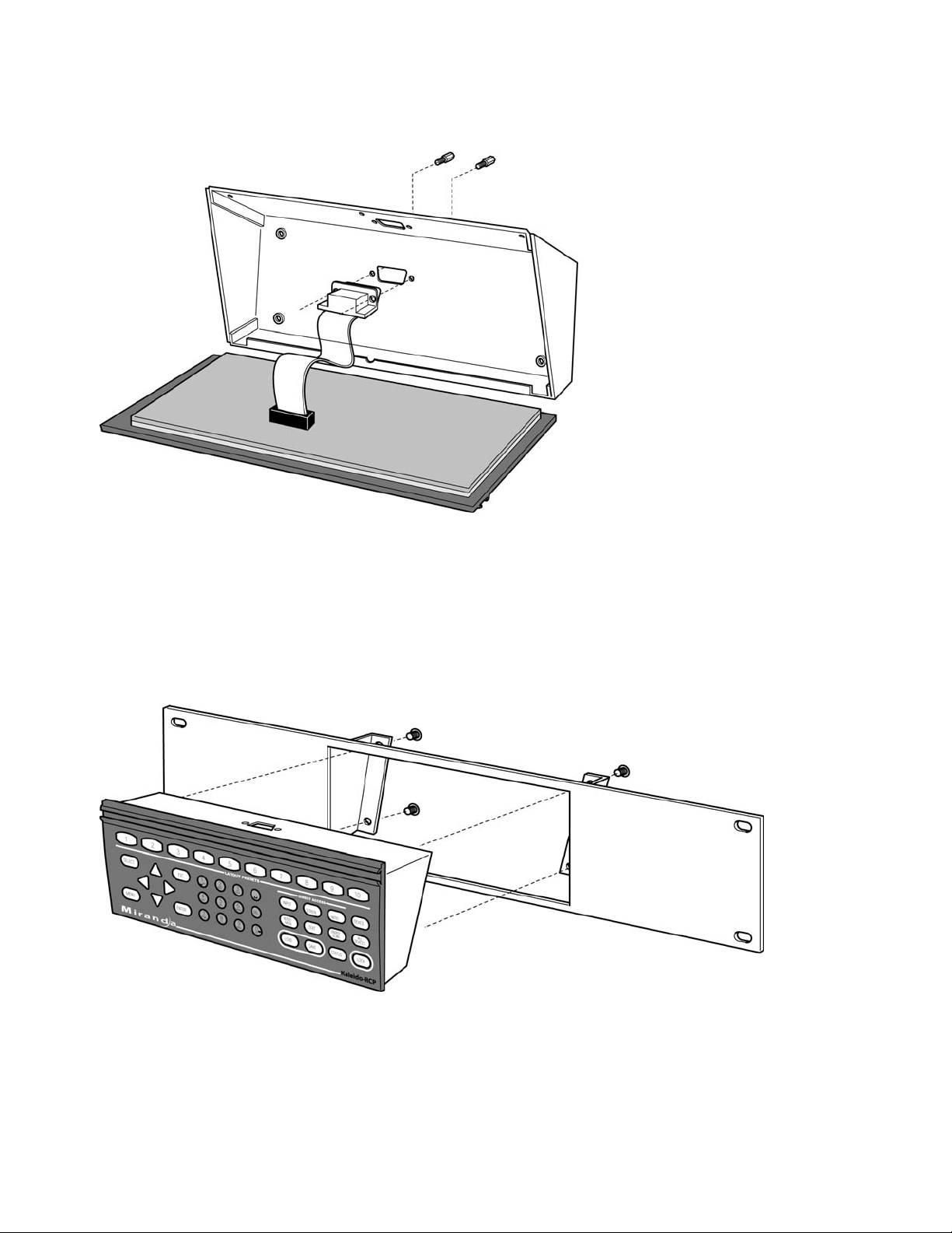
Before attaching the Kaleido-RCP to the mounting kit, you will need to move the RS-422 connector.
- Remove the 3 screws at the rear of the Kaleido-RCP.
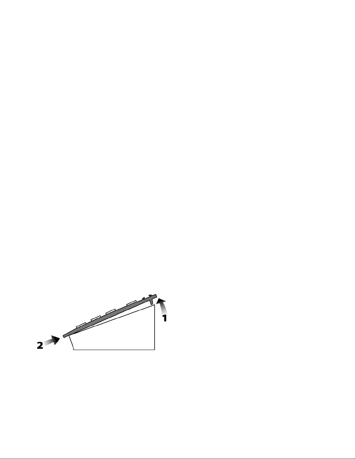
- Slightly lift the rear edge of the cover and push on the front edge toward the back of the unit to dislodge the cover
from the enclosure (figure 3.2.1).
Figure 3.2.1 Removing the cover
- Remove the 2 screws that hold the DE-9S connector to the enclosure.
- Pry out the metal plate that covers the DE-9 opening on the bottom of the enclosure. Attach the DE-9S connector
into this opening (figure 3.2.2).
- Re-install the cover on the enclosure.
4 | Kaleido K2
GUIDE TO INSTALLATION AND OPERATION
Figure 3.2.2 Moving the connector
Once the DE-9 connector is installed in the proper opening and the unit reassembled, do the following:
- Remove the 4 rubber feet on the underside of the unit.
- Place the Kaleido-RCP into the mounting bracket and secure it using the supplied screws (figure 3.2.3).
- Install the unit into the rack using the appropriate rack screws and washers (not provided).
Figure 3.2.3 Installing Kaleido-RCP into mounting kit
Kaleido K2 | 5
GUIDE TO INSTALLATION AND OPERATION
4 Frame and Electrical Installation
Kaleido is a self-contained unit consisting of a frame, redundant power supplies, a controller card, and various input
and output cards.
4.1 Frame
The frame is 4 RU high. It incorporates an internal midplane for interconnecting th e modules. Modules are installed
from the front of the frame. Each module is associated with input and/or output connectors which are mounted on a
connector panel. These connector panels are installed from the rear of the frame, in the same hori zontal p osition
as their associated module; they also plug into the midplane. The redundant power supplies are installed on the
right of the frame (as viewed from the rear). Their on/off switches are on the rear of the unit.
The front panel can be completely removed to give access to the modules. There are two knobs whi ch rotate
toward the top to release the panel. Immediately adjacent to each knob is a screw which blocks the rotation of the
knob. The screws must be removed before the panel can be opened. This provides security against casual access;
their presence has no effect on the functioning of the Kaleido.
The controller module incorporates a master ON/OFF button, and a CPU RESET button. Apertures in the frame
door provide access to these controls when the door is closed. Another aperture allows the controller module’s
POWER LED to be seen when the door is closed.
4.2 Power supplies
4.2.1 Installation
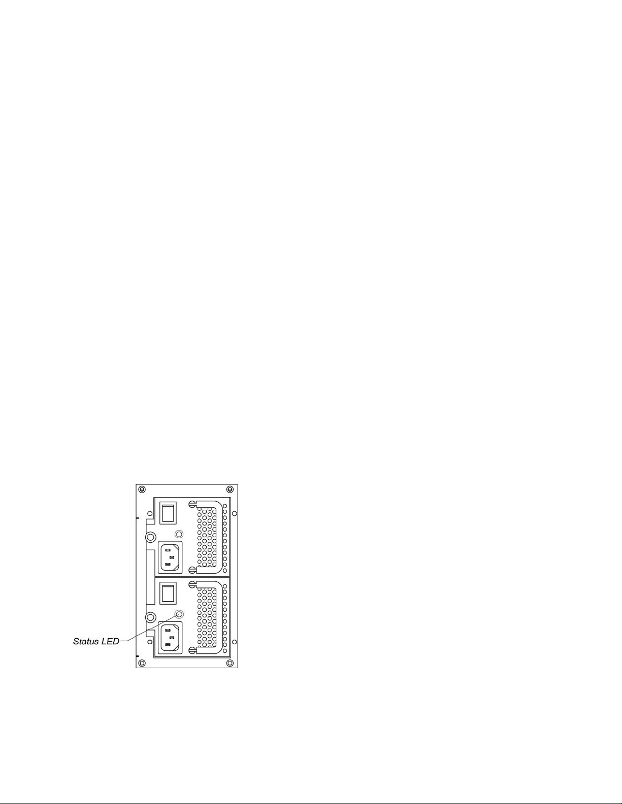
The Kaleido is powered by dual redundant power supplies. These are installed on the left side of the frame (right
side as viewed from the rear – see item 12 on fig. 4.5.1). The supplies are installed and removed from the rear of
the frame. To remove a power supply, release the captive screw at the left side, grasp the folding handle, and pull
the supply straight out of the frame. To install a supply, slide the module into position, and push gently on its front
panel until the connectors are seated and the panel is flush with the frame. Secure it in position with the captive
screw. These supplies are hot-swappable, so that a defective supply may be replaced without removing the
Kaleido from service.
Figure 4.2.1.1 Redundant power supplies
6 | Kaleido K2
 Loading...