

Page 1
SÉRIE DENSITÉ
VDA-1001
VDA-1001 - Analogue Video Distribution Amplifier
Operation and installation manual
M452-9900-100
February 2002
Introduction
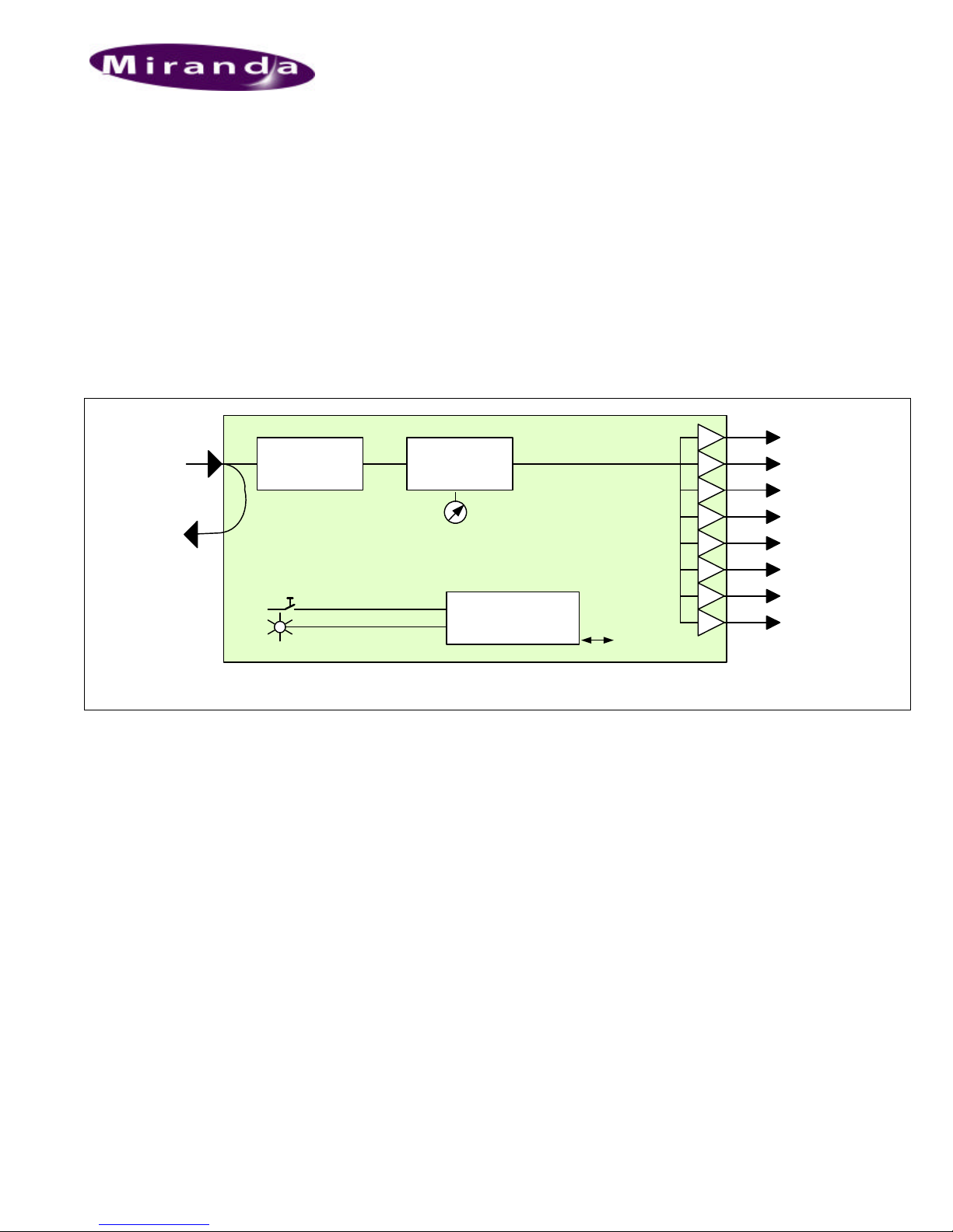
The VDA-1001 is an analogue video distribution amplifier with
a differential looping input and 8 outputs. Gain can be
controlled from the card edge. An input video signal status is
also available indicating the input signal presence. The
differential input provides rejection of hum and other artefacts
on incoming signals. The VDA-1001 is housed in a DENSITÉ
frame and requires a single or double rear connector panel.
INPUT
VIDEO
LT
Detection
signal
Select
Status
Gain
Features
• Analogue video differential input with passive loop-
• 8 x 75 Ohms outputs
• Supports 525/625 lines
• Supports PAL, SECAM and NTSC video standards
• 90 MHz analogue video bandwidth
• Control of gain from the card edge
• Status Led and remote reporting
Microcontroller
through
Rem Control
1
2
3
4
VIDEO
5
OUPUTS
6
7
8
VDA-1001 Functional Block Diagram
Technical specifications
Input
Signal: .........................................1 Vpp nominal
Return loss:.................................>45 dB up to 10 MHz
Coupling:.....................................DC
Level:...........................................0.3 to 1.5 Vcc
Impedance: .................................75 ohms
Common mode signal: ...............28 Vcc
Common mode rejection:............>65 dB to 10 kHz
Output
Signal (8): ................................... 1 Vpp nominal, ajustable
Return loss:.................................>45 dB up to 20 MHz
Impedance: .................................75 ohms
Phase match
between outputs: PAL -SECAM .. <0.1 ° @ 4.43 MHz
NTSC..............<0.1 ° @ 3.58 MHz
Cross talk: ...................................> 40 dB @ 10 MHz
Response variation:..................... <0.1 dB,
....................................................1 to 8 loads, to 20 MHz
Specifications are subject to change without notice..
Processing Performance
Gain: ..................................±3 dB
Frequency response: .........±0.02 dB up to 5 MHz
............................................±0.1 dB up to 10 MHz
............................................-3 dB @ 90 MHz typically
Differential gain:..................<0.15 %
Differential phase:...............<0.15 ° with 8 loads
............................................<0.1° with 2 load
Horizontal tilt: ......................<0.25% coupling DC
Vertical tilt: ..........................<0.25 % coupling DC
S/N :....................................>70 dB up to 15 MHz
............................................(rms noise/0.714V, unweighted)
Chroma/luma delay: ...........< ±1 ns
Chroma/luma gain: .............< ±0.02 dB
HUM: ..................................<1 mV
Processing delay ................15 ns
Power:.................................single 1.5 W
............................................double 2W
Page 2
VDA-1001
Operation and installation manual
Exploitation
Menu Introduction
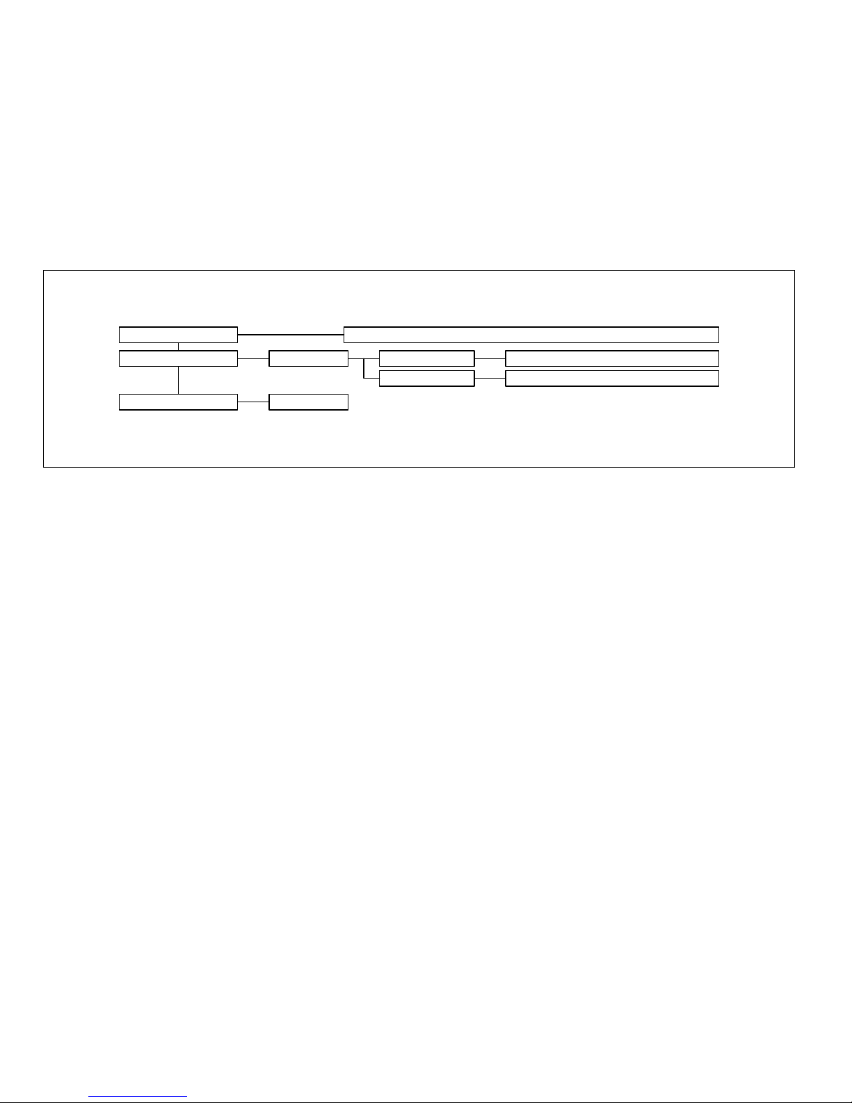
Parameters are accessed and changed via an easy-to-use menu. The flow chart below outlines the entire VDA-1001 menu path.
Each menu is described throughout this section.
The procedure and the operation mode are described in the common paragraph of the DENSITÉ Manual. The menu organisation
is made out of a main menu and several sub-menus. A press on the [SELECT] front panel push button accesses to the menu. A
lack of activity turns off the display. Default values are written with bold characters.
STATUS
CONFIGURE ALARM
FACTORY DEFAULT
NO SIGNAL ALARM LEVEL
RESTORE
REAR PANEL ERROR, OK 525, OK 625, NO SIGNAL
Menu Description
{STATUS}
Displays status of the different board alarms. The higher-level
alarm is displayed, even if not configured to activate the
STATUS Led..
REAR PANEL ERROR Indicates an absence of the rear panel
or an incompatibility between the
module and the rear panel. The
STATUS led turns on flashing red.
GREEN, YELLOW, RED, FLASH RED
ALARM REPORT NONE, GPI
OK 525 Indicates the incoming signal is a valid
525 lines signal.
OK 625 Indicates the incoming signal is a valid
625 lines signal.
NO SIGNAL Indicates an absence of incoming signal
Page 3

VDA-1001
Operation and installation manual
{CONFIGURE ALARM}
It is possible to associate the STATUS Led colour and/or a
GPI relay activation to each detected error.
Alarm relay activation depends of the ENABLE selection of
the controller board menu GPI REPORT.
ALARM LEVEL Associates to each error the STATUS
led colour: GREEN, YELLOW, RED
and FLASH RED. This selection has
no influence on the {STATUS} menu
display.
ALARM REPORT The default value NONE is assigned to
errors. Alarm relay activation will be
associated to an error when GPI is set.
Status and Report
This table shows the front Led colour and the report action according to the level of a given error condition. Notice that the
“Flashing Yellow” indicates that the SELECT button on the front panel has been pushed, and the card is being accessed via the
communication protocol.
Non requested
messages
No signal detected on Input µµ µµ -
{FACTORY DEFAUT}
RESTORE Set the module with the factory default
parameters.
GPI
Report
Green Yellow Red Flashing
Red
Flashing
Yellow
Card accessed via the communication protocol Yes
Rear Panel not matching - - - - - Yes Factory default.µµ
Note: The non requested message affectation to an alarm status can only be accessed by the communication protocol (serial port)
Page 4

VDA-1001
Operation and installation manual
Front Edge Presentation Board Presentation
P1
SW1
SW1
D1
STATUS
STATUS
D1
SELECT
SELECT
Push ButtonStatus Indicator
GAIN
Gain adjustment
VDA-1001
Configuration
P1
GAIN
GAIN AJUSTEMENT
Trimmer for gain adjustment
Connections
VDA-1001 is used with the single rear panel VDA-1001-SRP
that includes 1 input to 4 outputs or with the double rear panel
VDA-1001-DRP that includes 1 input to 8 outputs
VDA-1001-DRP VDA-1001-SRP
VIDEO IN
1
5
VIDEO IN
1
VIDEO OUT
2
3
4
VIDEO OUT
6
7
VDA-1001
8
VIDEO OUT
2
3
VDA-1001
4
 Loading...