

Page 1

UAP-711i/712i
Guide to Installation and Operation
Notice d'installation et d'utilisation
M289-9920-100
Single/Dual
Universal Audio
Processor with
Digital Outputs
Simple/Double
Processeur
Audio Universel
Copyright 2002 Miranda Europe
Specification may be subject to change
Printed in France
March 03
Copyright 2002 Miranda Europe
Les spécifications peuvent être modifiées sans préavis
Imprimé en France
mars 03
UAP
-
711i/712i
Miranda Europe
BP 87 - 93511 Montreuil Cedex
France
Tel: 33 (0)1 55 86 87 88
Fax: 33 (0)1 55 86 00 29
Email: francesale@miranda.com
www.miranda.com
Page 2

Warranty
This equipment is guaranteed for two years from the date of delivery. This covers all parts and labor at the factory.
Cost of shipping to and from the factory are payable by the client. This warranty applies to equipment which has been
used under normal conditions and which has not been repaired or modified in any way other than by Miranda Europe or
its authorized local distributor.
The above conditions of warranty may be cancelled by the general conditions of sale or by specific conditions of sale
established under the terms of particular contract.
All rights reserved
This publication is protected by copyright and all rights are reserved. No part of it may be reproduced or transmitted by
any means or in any form, without prior consent in writing from Miranda Europe.
The information in this manual has been carefully checked and is believed to be accurate. However, Miranda Europe
assumes no responsibility for any inaccuracies that may be contained in this manual. In no event will Miranda Europe be
liable for direct, indirect, special exemplary, incidental, or consequential damages resulting from any defect or omission
in this manual, even if advise of the possibility of such damages.
In the interest of continued product development, Miranda Europe reserves the right to make improvements in this
manual and the products describes at this time, without notice or obligation.
Garantie
Ce produit est garanti pour une durée de deux ans après la date de livraison. Elle porte sur les pièces défectueuses et
la main d’oeuvre.
Les frais de transport aller et retour sont à la charge du client. Elle s’applique sur tout matériel utilisé dans des
conditions normales et n’ayant pas subi d’intervention de réparation sans autorisation de Miranda Europe ou du
distributeur local agréé.
Toutefois, les conditions générales de vente ou d’éventuelles conditions particulières établies par contrat de vente
annulent totalement ou particulièrement les conditions ci-dessus.
Tous droits réservés
Cette publication est protégée par copyright et tous les droits sont réservés. Il est interdit de reproduire tout ou partie de
cet ouvrage ou de le transmettre sous quelque forme que ce soit, sans le consentement écrit préalable de Miranda
Europe.
Les informations décrites dans ce manuel ont été vérifiées avec soin et sont supposées exactes. Toutefois, Miranda
Europe ne peut être tenu responsable des erreurs ou des imprécisions qui auraient pu se glisser dans ce manuel, ni
des dommages directs ou indirects, exigés à titre exemplaire, spéciaux ou consécutifs à une erreur ou une omission
dans ce manuel, même s'il a été avisé de tels dommages.
Suite au développement continuel de ses produits, Miranda Europe se réserve le droit d'apporter des améliorations à ce
manuel et aux produits qui y sont mentionnés à tout moment, sans avoir à se justifier ou à notifier les personnes
concernées
How to Contact us:
Comment nous contacter:
Miranda Technologies inc.
Miranda Europe
Miranda Japan KK
3499 Douglas-B.-Floreani
Saint-Laurent, QC
Canada, H4S 2C6
BP 87
93511 Montreuil Cedex
France
Mita Nexus Bldg 2F
1-3-33 Mita, Minato-Ku
Tokyo, Japan 108-0073
Tel: 1 (514) 333 1772
Tel: +33 (0) 1 55 86 87 88
Tel: 81-3-5730-2988
Fax: 1 (514) 333 9828
Fax: +33 (0) 1 55 86 00 29
Fax: 81-3-5730-2973
1 800 224 78 82 asiasale@miranda.com
amersale@miranda.com francesale@miranda.com
www.miranda.com
Page 3

Guide to installation & Operation
UAP-711i/712i x 3
Guide to installation & Operation
1 General.....................................................................................5
1.1 Introduction..........................................................................5
1.2 Features..............................................................................5
2 Installation...............................................................................6
2.1 Unpacking ...........................................................................6
2.2 Mechanical installation.........................................................6
2.2.1 imaging Quartet series trays..................................................................6
2.2.2 imaging Symphonie Housing Frame.....................................................7
2.3 Rear panel label..................................................................8
2.3.1 Quartet frame.........................................................................................8
2.3.2 Symphonie Frame..................................................................................8
2.4 Electrical installation............................................................9
2.4.1 AES3 110 Ω rear panel.......................................................................... 9
2.4.2 AES3-id 75 Ω rear panel........................................................................9
2.4.3 Pin assignment ....................................................................................10
2.5 Applications.......................................................................11
2.5.1 Analog inputs & outputs connections...................................................11
2.5.2 Digital inputs & outputs connections....................................................11
2.5.3 Synchronization ...................................................................................11
2.5.4 Fixed or remote controlled delay..........................................................12
2.5.5 0dBFS..................................................................................................12
2.5.6 GPI Outputs......................................................................................... 12
3 Operation...............................................................................13
3.1 UAP-711i or UAP-712i user interface ................................13
3.2 Configurations and adjustments ........................................14
3.2.1 Jumper and switches location..............................................................14
3.2.2 Configuration........................................................................................ 15
3.3 Menu introduction..............................................................16
3.4 Menu organization.............................................................17
3.4.1 The input status menu {STAT}.............................................................19
3.4.2 The input selector menu {SEL} ............................................................20
3.4.3 The delay menu {DLAY}....................................................................... 20
3.4.4 The channel swapping Menu {SWAP}.................................................21
3.4.5 The pre-mix level adjustment menu {LVL} ...........................................21
3.4.6 The phase inversion menu {PHSE}......................................................21
3.4.7 The mixing menu {MIX} ........................................................................22
3.4.8 The tone generator menu {TEST}........................................................ 22
3.4.9 The output level adjustment menu {OLVL}...........................................23
3.4.10 The mute (AES silence) menu {MUTE}............................................23
3.4.11 The monitoring menu {MNTR}..........................................................24
3.4.12 The alarm deactivation menu {ALRM}..............................................25
3.4.13 The video synchronizer interface menu {ABUS}............................... 25
3.4.14 The channel status mode menu {CHST}..........................................26
3.4.15 The AES coding mode menu {AES}.................................................26
3.4.16 The Origin message Menu {ORIG}...................................................26
3.4.17 The destination message Menu {DEST}...........................................27
3.4.18 The sample rate & word length menu {SRWL}.................................28
3.4.19 The setup menu {CONF}..................................................................29
4 Technical Specifications.......................................................30
1 Généralités............................................................................. 32
1.1 Introduction........................................................................32
1.2 Caractéristiques.................................................................32
2 Installation.............................................................................33
2.1 Livraison............................................................................33
2.2 Installation mécanique.......................................................33
2.2.1 Installation en coffret Quartet...............................................................33
2.2.2 Installation en châssis Symphonie.......................................................34
Page 4

Guide to installation & Operation
4 x UAP-711i/712i
2.3 Le lexan d'identification ......................................................35
2.3.1 Châssis Quartet ...................................................................................35
2.3.2 Châssis Symphonie..............................................................................35
2.4 Installation électrique.........................................................36
2.4.1 Face arrière A110 Ω.............................................................................36
2.4.2 Face arrière 75 Ω.................................................................................36
2.4.3 Affectation connecteurs........................................................................37
2.5 Applications .......................................................................38
2.5.1 Raccordement des entrées et sorties analogiques ..............................38
2.5.2 Raccordement des entrées et sorties numériques...............................38
2.5.3 Synchronisation....................................................................................38
2.5.4 Délai fixe et délai télécommandé .........................................................39
2.5.5 0 dBFS.................................................................................................39
2.5.6 Les sorties GPI.....................................................................................39
3 Exploitation............................................................................ 40
3.1 Présentation des composants de face avant......................40
3.2 Configuration et réglages...................................................41
3.2.1 Localisation des cavaliers et des switches...........................................41
3.2.2 Configuration........................................................................................42
3.3 Introduction aux Menus .....................................................43
3.4 Architecture des menus.....................................................44
3.4.1 Le menu d’état des signaux d’entrée {STAT}.......................................46
3.4.2 Le menu sélecteur d’entrée {SEL}........................................................47
3.4.3 Le menu ligne à retard {DLAY}.............................................................47
3.4.4 Le menu grille de commutation {SWAP} ..............................................48
3.4.5 Le menu de réglage du niveau avant mélange {LVL}...........................48
3.4.6 Le menu inversion de phase {PHSE}...................................................49
3.4.7 Le menu sommation {MIX}...................................................................49
3.4.8 Le menu générateur de tonalité {TEST}...............................................50
3.4.9 Le menu de réglage du niveau de sortie {OLVL}..................................50
3.4.10 Le menu coupure de voie, silence AES {MUTE} ..............................50
3.4.11 Le menu contrôle d’écoute {MNTR}..................................................51
3.4.12 Le menu désactivation des alarmes {ALRM}....................................52
3.4.13 Le menu interface synchroniseur vidéo {ABUS}...............................52
3.4.14 Le menu de gestion des bits d’état de voie {CHST}..........................53
3.4.15 Le menu de codage AES {AES} .......................................................53
3.4.16 Le menu ORIG..................................................................................53
3.4.17 Le menu DEST.................................................................................54
3.4.18 Le menu format de sortie AES {SRWL}............................................55
3.4.19 Le menu réglages par défaut {CONF} ..............................................56
4 Spécifications........................................................................57
Appendix - Annexe.........................................................................60
Page 5

Guide to installation & Operation
UAP-711i/712i x 5
1 General
1.1 Introduction
The UAP-711i/712i are high-quality universal audio processors. The UAP-711i processes one stereo
analog or AES channel while the UAP-712i can process two stereo analog or AES channels.
The audio channels can be individually swapped, phase inverted, muted, summed and level adjusted.
Both modules provide 2 delay elements: a user-adjustable fixed delay and a video tracking delay. The
fixed delay can be set for up to 10 s. The video tracking delay is received directly from an external video
frame synchronizer (ASD-231i, DVP-101i, FRS-111i).
For use in a mixed analog/digital environment, both analog and digital AES input and output are
provided. The digital outputs can be locked to an external reference signal (video, DARS or word clock).
A built-in tone source generator is available to facilitate audio levels settings. These powerful features
make the UAP-711i/712i ideal for handling incoming analog audio feeds.
The UAP-711i/712i’s flexible and complete feature set make it ideal for in-studio and incoming feed
processing applications
1.2 Features
• Two independent stereo or AES inputs
• Input signal can be analog, digital or de-embedded AES coming from video synchronizer via ABUS
• Analog and digital outputs
• 24 bits digital audio processing
• 32, 44.1, 48 and 96 kHz sampling rate
• -96 to +12 dB of input and output level adjustments
• Fixed and video tracking delay up to 10 s (@ 48kHz)
• Full 4X4 channel swapping
• Phase reversal
• 2 or 4 input mix-down
• Locks to video, AES, word clock and video synchronizer
• Internal EBU tone generator
• Monitoring functions
• Alarm outputs (GPI)
• AES3 and AES-3id support
• 4 (or 2) high quality analog audio outputs
• 0 dBFS adjustment: +24, +22, +21, +20, +18, +16, +15 dBu
• 2 user defined setups
Page 6

Guide to installation & Operation
6 x UAP-711i/712i
2 Installation
2.1 Unpacking
Make sure the following have been shipped with your UAP-711i or UAP-712i. If any of the following
items are missing, contact your distributor or Miranda Europe.
• UAP-711i or UAP-712i
• UAP-711i/UAP-712i rear panel labels::
One for R-AX Symphonie rear panel
One for R-A110 rear panels
2.2 Mechanical installation
The UAP-711i or UAP-712i must be mounted within Quartet-A110 tray or in Symphonie equipped with
rear module R-AX or R-A110 in order to provide power to the card.
This section describes how to install the UAP-711i or UAP-712i in any of these trays. It is not necessary
to switch off the power from these trays when installing the UAP-711i or UAP-712i
2.2.1 imaging Quartet series trays
To install this card into Quartet follow these steps. For a closer look at card installation and removal,
refer to the tray's technical manual.
1. Remove the tray's front panel by rotating the thumbscrews counter clockwise. Pull on the
handles.
2. Select an empty slot
3. Carefully place the UAP-711i or UAP-712i between a set of card guides and gently push
the card towards the rear of the tray until the card edge connector is secured to the back
plane. The card's edge connector having 96 points, it may be necessary to push lightly
when connecting the two connectors. Pull lightly on the card verifying that it does not
move.
4. Replace the tray's front panel. Make sure to rotate the thumbscrews clockwise in order to
secure it to the chassis.
Page 7
Guide to installation & Operation
UAP-711i/712i x 7
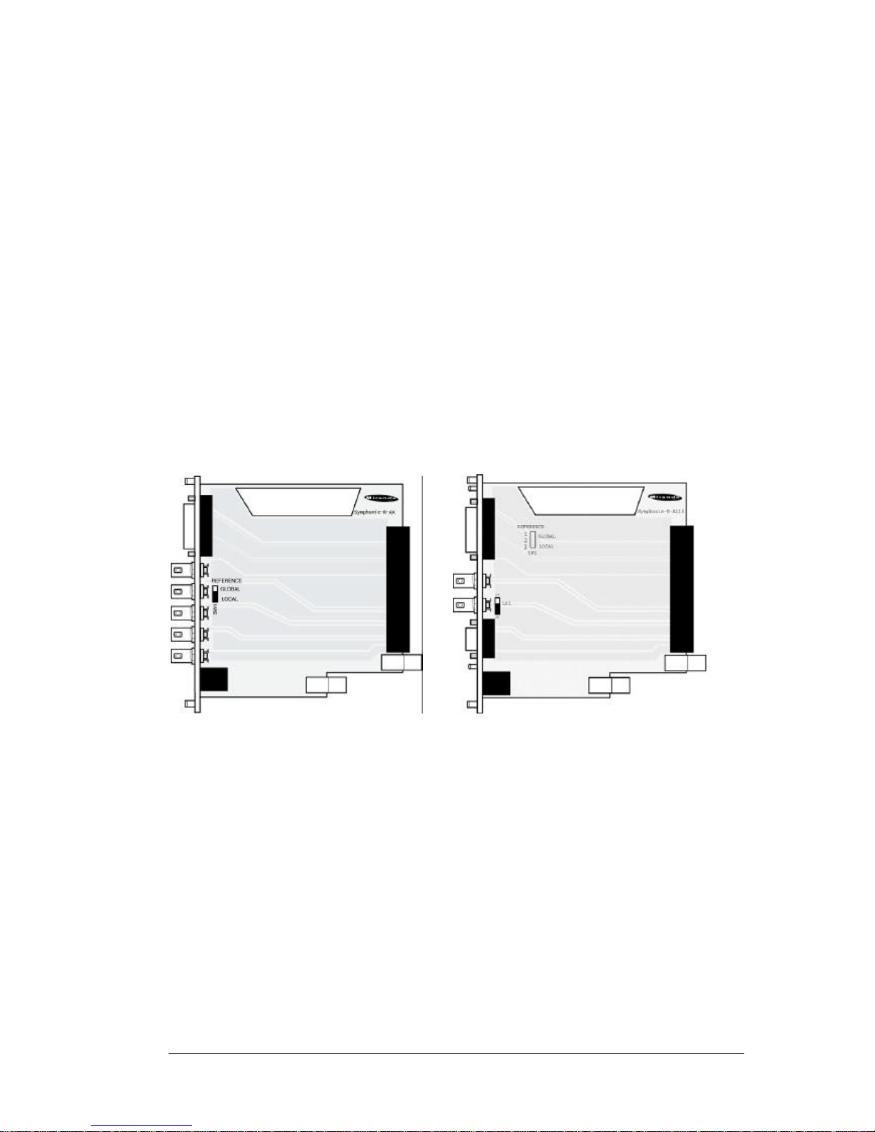
2.2.2 imaging Symphonie Housing Frame
It is not necessary to switch off the power when installing or removing a module from/to Symphonie. To
install a module, follow these steps. For a closer look at card installation and removal, refer to the
housing frame's Guide to Installation and Operation.
Rear Module Installation
Before installing, check the rear panel corresponds to the card to install. If no rear module is present,
follow the procedure below to install it.
In order to maintain the inter-rear module spacing, make sure to remove and replace one rear module
at a time. That is, at all times, there must be at least 15 rear modules installed. To install a module,
follow these steps.
1. Locate an empty compartment.
2. Make sure that the rear panel corresponds to the card to install, the Reference switch LK1
is used to select the (75 Ω) reference source for the imaging module. Selecting LOCAL
(LK1 position 2-3) drives the reference signal, connected to the rear module, to the imaging
module. However, sliding LK1 to position 1-2, connects the imaging module to the
Symphonie global reference.
3. Carefully place the rear module between the rear module guides (refer to Figure 2.4) and
slowly push the module towards the front until it rests against the rear panel. It may require
a light pressure to compress the EMI gaskets on.
4. Using a flat edge screwdriver, secure the top and bottom screws to the frame.
Figure 1: Rear panels for Symphonie
Board installation
1. Open the front panel door by pulling on the door handles and gently lowering it.
2. Unscrew the module-retaining bar.
3. Carefully place the module between the module guides and slowly push the module
towards the rear of the frame until the module's edge connector is secured to its rear
module. A light pressure to mate the connectors may be required. Pull lightly on the
module verifying that it does not move.
4. Replace the bar.
5. Replace the front panel door.
Page 8

Guide to installation & Operation
8 x UAP-711i/712i
2.3 Rear panel label
2.3.1 Quartet frame
Two connector labels have been shipped with your UAP-711i or UAP-712i. One label is to be connected
on the Quartet tray rear panel in order to identify the UAP-711i or UAP-712i external connectors. UAP711i corresponds to only channel 1; UAP-712i corresponds to channel 1 and 2. The rear panel is
always equipped with UAP-712i rear panel.
1. To install the label, follow these steps
2. On the tray's rear panel, locate the UAP-711i or UAP-712i connectors
3. Carefully, apply the label to the connectors
Figure 2: Example of label installation
2.3.2 Symphonie Frame
To install the Symphonie label, follow these steps while
referring to Figure below
1. On Symphonie ’s rear panel, locate the
appropriate connectors.
2. Carefully apply the label to the connectors
making sure the label’s text is read from top to
bottom.
Figure 3: Symphonie rear panel label installation
Page 9
Guide to installation & Operation
UAP-711i/712i x 9
2.4 Electrical installation
When connecting the UAP-711i or UAP-712i to external equipment, make sure that all digital
connections are point-to-point. Refer to the figure below and to the following descriptions for a complete
UAP-711i or UAP-712i installation.
This equipment is conform to the CEE 89 / 336 directive and operation is subject to the
following two conditions:
1- this equipment may not cause harmful interference according to EN 50081-1
rules.
2- this equipment must accept any interference received, according to EN
50082-1 rules.
Precaution of use:
Several components included are very static-sensitive. To avoid damaging those components,
be sure to respect the following rules:
1- Before touching any component or any other element of the card make sure
to reduce any static electricity on your person. One way to do this is to touch a
surface connected to ground, or to wear a wrist strap attached to ground.
2- when handling card, hold it by the edges avoiding touching the components.
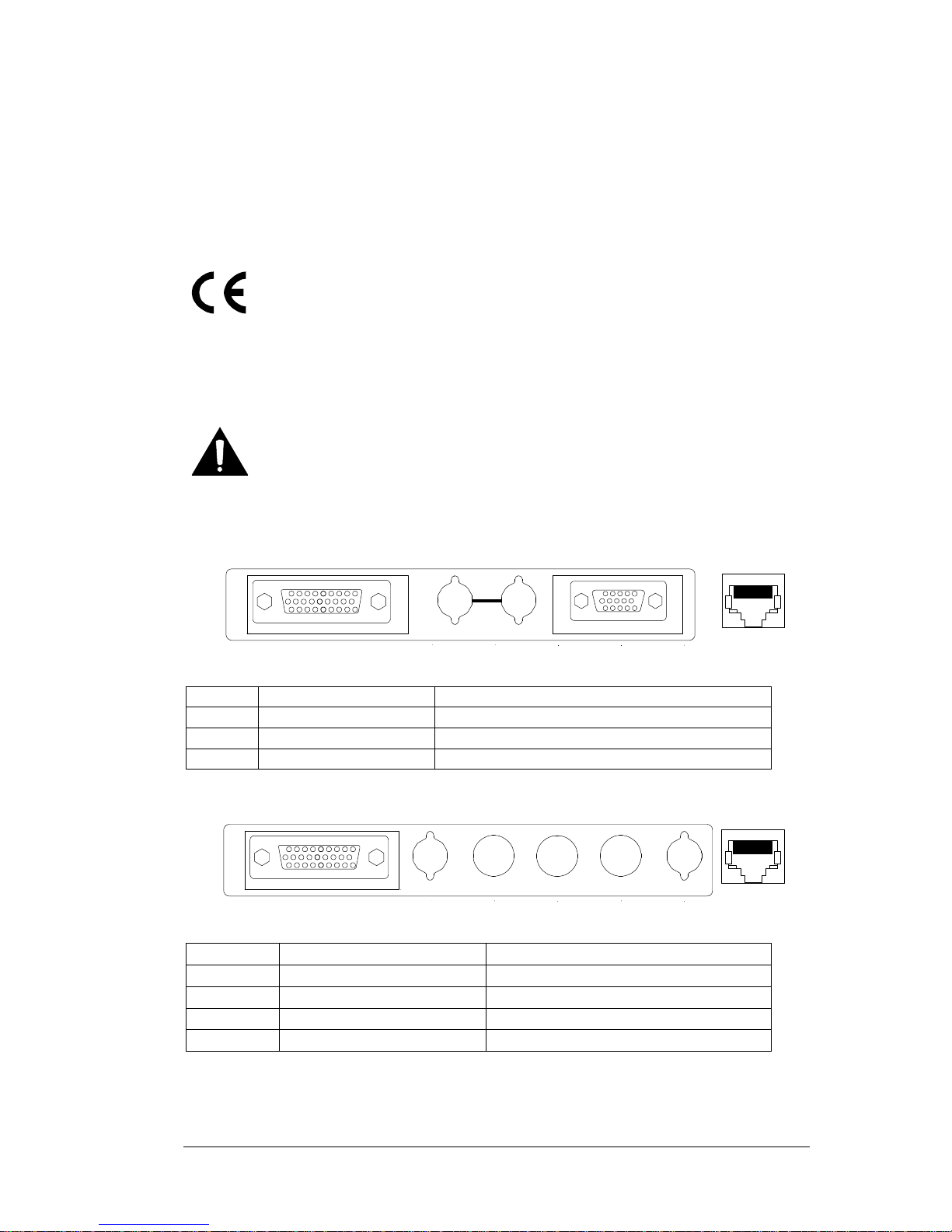
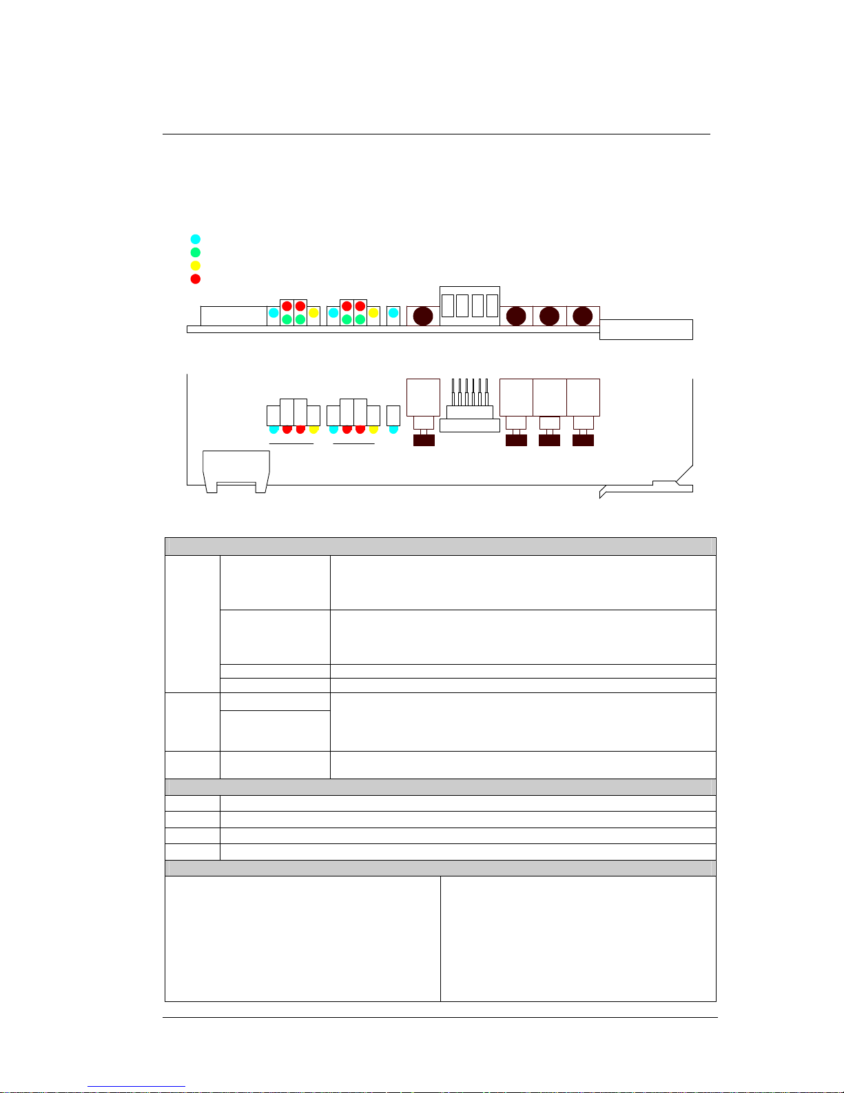
2.4.1 AES3 110 Ω rear panel
UAP-712i
ANALOG
REF . IN
GPI
AES
Figure 4: Quartet-A110 or Symphonie-R-A110 rear panel
ANALOG
26 point HD female socket Analog audio inputs & outputs
REF.IN
BNC jacks Reference input with passive loop-through
AES
15 point HD female socket AES3 digital audio I/O’s and reference input
REM
RJ45-10 socket GPI alarm outputs, delay remote control inputs
2.4.2 AES3-id 75 Ω rear panel
UAP-712i
ANALOG
IN 1 REF. IN IN 2 OUT 1 OUT 2
GPI
Figure 5: Symphonie-R-AX rear panel
ANALOG
26 point HD female socket Analog audio inputs & outputs
REF.IN
BNC jacks Reference input
IN1, IN2
BNC jacks AES3-id digital audio inputs
OUT1, OUT2
BNC jacks AES3-id digital audio outputs
REM
RJ45-10 socket GPI alarm outputs, delay remote control inputs
Page 10
Guide to installation & Operation
10 x UAP-711i/712i
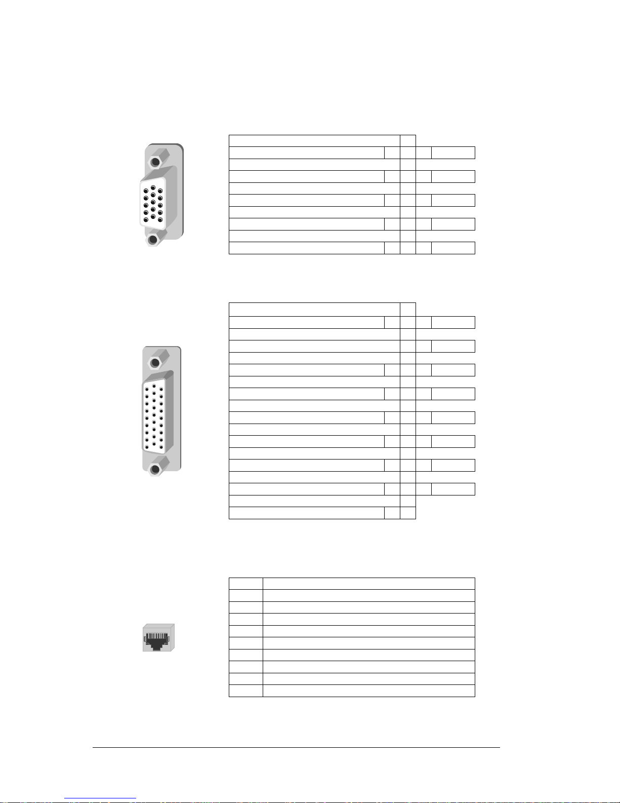
2.4.3 Pin assignment
UAP-711i corresponds to channel 1only; UAP-712i corresponds to channel 1 and 2.
AES (15 points high density D-SUB socket): AES3 digital audio I/O’s and reference input
AES OUT 1 Low
6
AES OUT 1 High
1 11
Gnd
AES OUT 2 Low
7
AES OUT 2 High
2 12
Gnd
AES Ref IN Low
8
AES Ref IN High
3 13
Gnd
AES IN 2 Low
9
AES IN 2 High
4 14
Gnd
AES IN 1 Low
10
AES IN 1 High
5 15
Gnd
Figure 6: AES pin assignment
ANALOG (26 points high density D-SUB socket):
IN 1 Left Low
10
IN 1 Left High
1 19
Gnd
IN 1 Right Low
11
IN 1 Right High
2 20
Gnd
IN 2 Left Low
12
IN 2 Left High
3 21
Gnd
IN 2 Right Low
13
IN 2 Right High
4 22
Gnd
OUT 1 Left Low
14
OUT 1 Left High
5 23
Gnd
OUT 1 Right Low
15
OUT 1 Right High
6 24
Gnd
OUT 2 Left Low
16
OUT 2 Left High
7 25
Gnd
OUT 2 Right Low
17
OUT 2 Right High
8 26
Gnd
Gnd
18
Gnd
9
Figure 7: analog audio inputs & outputs
GPI (RJ45-10 socket): GPI outputs, delay remote control inputs
1
Gnd
2
Error output : NO LOCK1
3
Error output : ANALOG 1
4
Input Channel 1 Delay (HI)
5
Input Channel 1 Delay (LO)
6
Input Channel 2 Delay (HI)
7
Input Channel 2 Delay (LO)
8
Error output : NO LOCK2
9
Error output : ANALOG 2
10
NC
Figure 8: Remote pin assignment
Page 11

Guide to installation & Operation
UAP-711i/712i x 11
2.5 Applications
2.5.1 Analog inputs & outputs connections
Inputs connections
The IN1L, IN1R, IN2L and IN2R jumpers select the impedance value for each input: a jumper ON
selects a 600 Ω input impedance. When OFF the impedance is >10 kΩ.
Outputs connections
The equipment connected to the UAP-711i or UAP-712i is supposed to be high impedance.
When the equipment connected to UAP-712i has an input impedance equal to 600 Ω, the power rating
allowed for one slot is exceeded. In that case two slots are required for one UAP-712i. The single
module UAP-711i will support 600 Ω loads without power limitations.
2.5.2 Digital inputs & outputs connections
When used with an AES3-id 75 Ω rear panel (Symphonie R-AX), switches SW4, SW51, SW53, SW61,
SW63, SW71, SW73, SW81, SW83, SW91 must be set on the A75 position.
When used with an AES3 110 Ω rear panel (Quartet A110 or Symphonie R-A110), switches SW4,
SW51, SW53, SW61, SW63, SW71, SW73, SW81, SW83, SW91 must be set on the A110 position.
2.5.3 Synchronization
When the AES ouputs are used, an external reference signal may be required to synchronize these
digital outputs.
The detection of the reference standard is automatic. An AES3 digital audio reference signal connected
at the AES Sub-D has a higher priority than any reference signal connected to the BNC jack.
In stand-alone mode the REF led, when green, indicates compatibility between the sync signal and the
AES output-sampling rate selected. It will be orange if the AES output signals are not synchronized to a
reference signal.
When used in conjunction with a video processor, the reference source is the video module that delivers
a 27 MHz reference signal (via the ABUS front panel connector). The REF led will be green to indicate
the validity of this 27 MHz, orange when it is not valid but with an external valid reference signal
connected at the rear, and red in other cases.
The relative phase between external sync signal and AES samples is respected for any case except for
mode video NTSC. For video PAL mode, output samples are aligned with the start of the first line.
RA-110 rear panel The AES 110 Ω Sync input is located on "AES" Sub-D socket. The switch “LD110”
must be set on the LOZ position to properly terminate the line. Other syncs are
connected on BNC jack "REF.IN". The switch “LD75” must be set on the LOZ
position to properly terminate the line. The second BNC jack is lined to "REF.IN"
input and may be used as loop-through. For this conditional use, the switch
“LD75” must be set on the HIZ position.
RA-X rear panel The sync signal must be connected on BNC "REF.IN". The switch “LD75” must be
set on the LOZ position to properly terminate the line.
When used in a Symphonie frame, the module 75 Ω ??reference input can be connected to the global
reference signal (video or Word Clock only) instead of the BNC REF.IN. It is done by sliding LK1 to
position 1-2 (GLOBAL) on the rear panel and SW4 to position A75 on the module, regardless of the rear
panel
Page 12
Guide to installation & Operation
12 x UAP-711i/712i
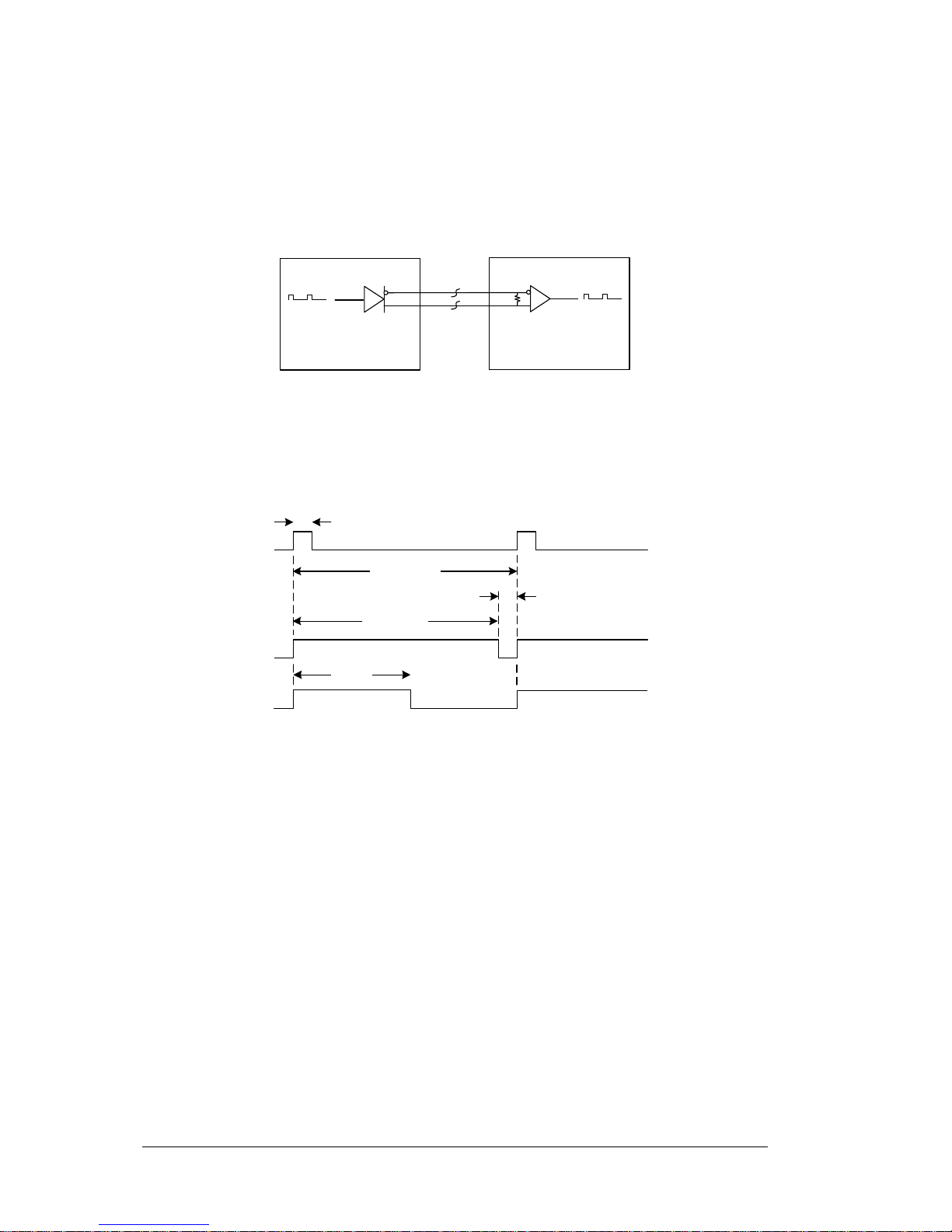
2.5.4 Fixed or remote controlled delay
The module can delay the signal up to 10 sec (@48 kHz). This delay can be user adjusted (Fixed
mode) by 1 ms step. A part of the maximum delay can be reserved and applied by a remote controlled
signal (Tracking mode).
This signal uses electrical transport of a RS 422 path.
Video Processing Module
Audio Processing Module
VPD signal VPD signal
Figure 9: Tracking signal
The signal period corresponds to the maximum delay reserved by the main module (T) and the positive
pulse width (tproc) corresponds to the required delay. For a sudden variation, UAP-711i or UAP-712i
integrates this modification within 15 sec for a variation of 40 ms.
t
PROC
(MIN)
T (period)
t
PROC
(MAX)
t
LOW
t
PROC
Figure 10: Time chart
The reserved part of delay is subtracted from the accessible entire delay value in “fixed” mode if the
“tracking” mode is active. Up to four modules can share the same tracking signal.
2.5.5 0dBFS
The three switches SW1, SW2 and SW3 set the RMS value of sine wave corresponding to a 0 dBFS
digital level with gain adjustments set to 0 dB.
2.5.6 GPI Outputs
Four open-collector GPI outputs (two for each channel) are available on the GPI socket. For each
channel, one output is dedicated to a signal overload (with analog or digital input selected) and the
other to a no-lock condition on the digital input. In the absence of alarm, no current flows through an
output pin. These outputs are inactive when the alarms are disabled (ALRM menu, OFF selected)
Page 13
Guide to installation & Operation
UAP-711i/712i x 13
3 Operation
3.1 UAP-711i or UAP-712i user interface
The Figure below illustrates the UAP-711i or UAP-712i user interface situated at the front end of the
card. For information on these controls, refer to the rest of this section.
UAP-712i
-
ABUS
TOP VIEW
YELLOW
INPUT 2
LOCK
+
SELECT
RED
BICOLOR
UNIVERSAL AUDIO PROCESSOR
ESC.
INPUT 1
FRONT VIEW
GREEN
RL TEST LOCK RL TEST REF
UAP-711i
UAP-712i
Figure 11: UAP-711i or UAP-712i user interface
Status leds
LOCK (bi-color)
Green: AES signal detected.
Orange: non-audio signal detected.
Red: indicates parity error, coding error or a no lock condition on
AES input.
L (1 green + 1 red)
The two Leds are assigned to channel 1 left after the ANLG, DIGT or
Abus input selector.
Green: lights when a signal is present (threshold –60 dBFS).
Red: indicates overload or an absence of signal for 15 seconds.
R (1 green + 1 red)
These two Leds correspond to channel 1 right.
INPUT 1
TEST (yellow)
EBU tone or mute selected.
LOCK (bi-color)
INPUT 2
L (1 green + 1 red)
R (1 green + 1 red)
TEST (yellow)
These Leds correspond to input 2.
REF (Bi-color)
Green, orange or red: indicates the lock/no-lock condition of the AES
outputs (refer to synchronization paragraph 2.5.3)
Front panel pushbuttons
[SEL]
Activates the displayed parameter
[-]
Decreases value of selected parameter
[+]
Increases value of selected parameter
[ESC]
Returns to previous parameter
Main menu parameters
Input status
Input Selector
Delay
Channel swapping
Input level adjustment
Phase Inversion
Mixing
Test (tone generator)
Output level adjustment
Mute (AES silence)
Monitoring functions
Alarm deactivation
ABUS (interface with video synchronizer)
AES channel status source
AES mode (Pro. or Consumer)
AES Origin and destination message
AES output format
Factory configurations
Page 14
Guide to installation & Operation
14 x UAP-711i/712i
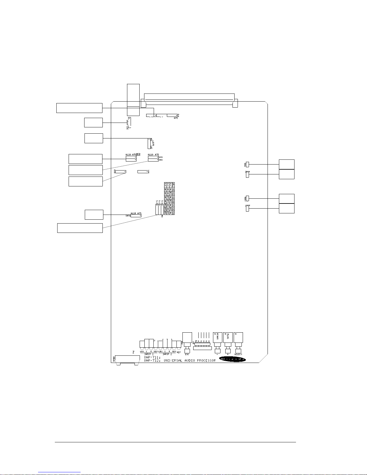
3.2 Configurations and adjustments
3.2.1 Jumper and switches location
SW53 - SW51 - SW4
LD110
LD75
SW73 - SW83
SW71 - SW81
SW61 - SW63
SW91
SW1 - SW2 - SW3
IN1L
IN1R
IN2L
IN2R
Figure 12: Switches location
Page 15
Guide to installation & Operation
UAP-711i/712i x 15
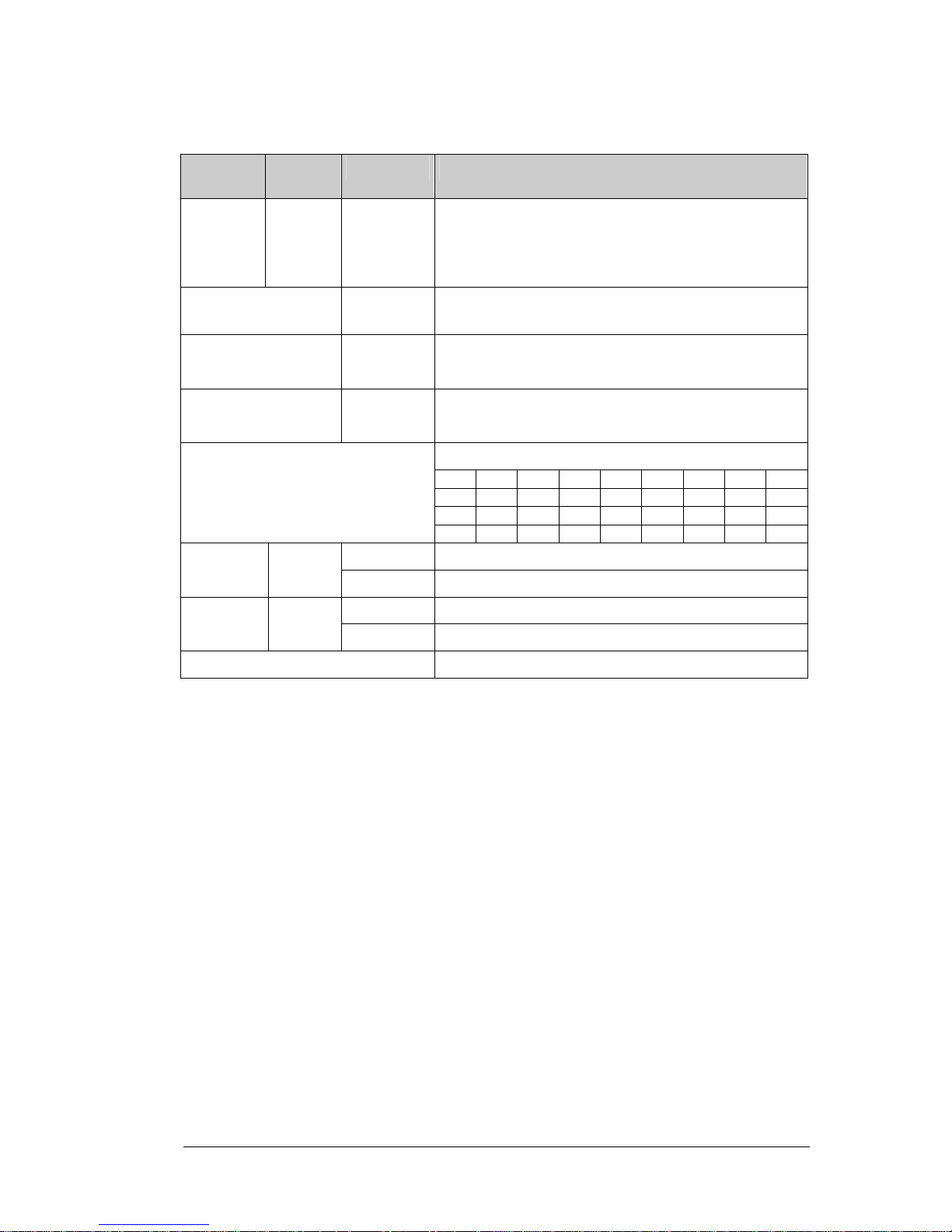
3.2.2 Configuration
Switch
Channel 1
Switch
Channel 2
Position Designation
A75 Rear panel selection (75 or 110 Ω) SW51
SW61
SW71
SW81
SW91
SW53
SW63
SW73
SW83
A110
A75 SW4
A110
Rear panel selection (75 or 110 Ω)
{REF.IN passive loop respectively (OFF or ON)}
LOZ 75 Ω termination associated to “REF.IN” input LD75
HIZ
LOZ 110 Ω termination associated to AES3 reference input LD110
HIZ
Analog RMS value associated to 0DBFS
dBu +15 +16 +18 +20 +21 +22 +24 +24
SW1
ON OFF ON OFF ON OFF ON OFF
SW2
ON ON OFF OFF ON ON OFF OFF
SW1, SW2, SW3
SW3
ON ON ON ON OFF OFF OFF OFF
ON 600 Ω input impedance Analog left input IN1L IN2L
OFF 12 kΩ input impedance Analog left input
ON 600 Ω input impedance Analog right input IN1R IN2R
OFF 12 kΩ input impedance Analog right input
J9 Spares jumpers
Page 16

Guide to installation & Operation
16 x UAP-711i/712i
3.3 Menu introduction
Most UAP-711i or UAP-712i parameters are accessed and changed via an easy-to-use menu. The flow
chart below outlines the entire UAP-711i or UAP-712i menu path. Each menu is described throughout
this section. The following items should be remembered when accessing the menu.
Automatic display turn off after 1-minute interval
If the menu is currently being accessed and no push -button has been pressed for 1 minute, the UAP711i or UAP-712i automatically turns off the display. A press on any push button [-], [+] or [SEL] will turn
on the display without any change on the current parameter.
Navigating through the menu
This section describes how to use the front panel push buttons to navigate through the menu.
[+] Press [+] to move down in the menu or to increase the parameter value. For example, if
you are currently at {I-1&2}, pressing [+] will scroll downwards through the selection {I-1}.
Depressing [+] during an adjustment will increase the parameter value at faster rate.
[-] Press [-] to move up in the menu or to decrease the parameter value. For example, if you
are currently at {PHSE}, pressing [-] will scroll through the selections {LVL}, {SWAP},
{DLAY} and {STAT}.
Depressing [-] during an adjustment will decrease the parameter value at faster rate.
[SEL] Changes to a menu parameter are stored immediately to non-volatile memory. For
example, after the L gain value has been set, press [SEL] and the new value is stored for
the current format and UAP-711i or UAP-712i returns to previous menu.
[ESC] If [ESC] is pressed after changes to a parameter, the parameter is reset to the value it had
prior to the change, For example, after changing L level, press
[ESC] the previous value is reloaded and UAP-711i or UAP-712i returns to previous menu.
When on root menu, a press on [ESC] turns off the display.
Note: If the L and R values are different, the L value will be displayed after a L&R selection. On
the same way, the channel 1 value will be displayed after an I-1&2 or O-1&2 selection.
Modify the displayed parameter attached to the 1&2 selection to change the channel 2
value.
Page 17
Guide to installation & Operation
UAP-711i/712i x 17
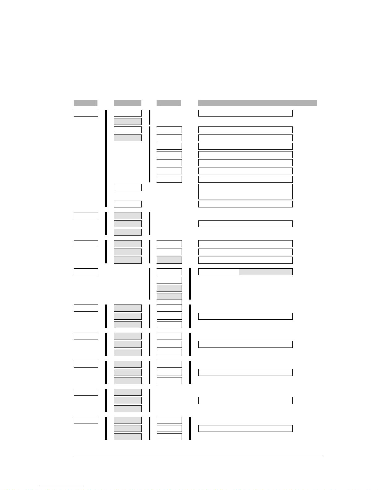
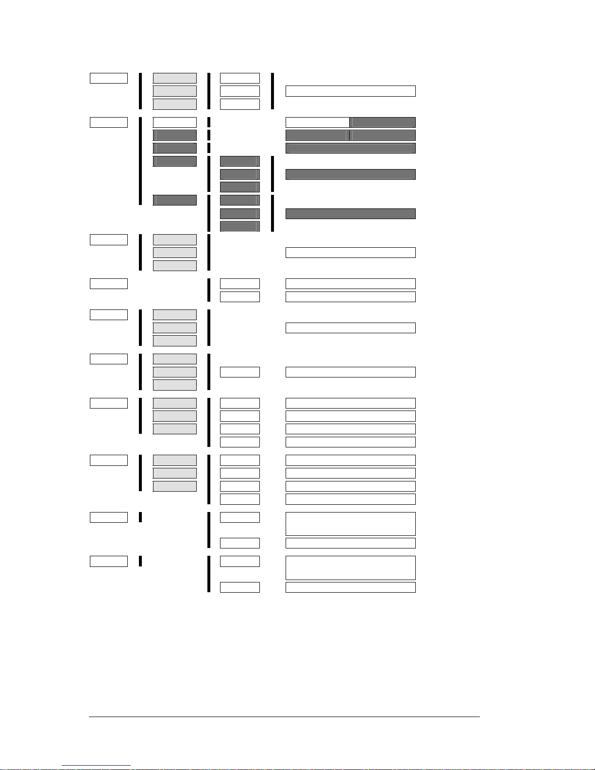
3.4 Menu organization
The architecture of the menus is built around main menus and secondary menus. Display disappears
after one minute and will reappear by pressing any of push-button button [-], [+] or [SEL]. Default values
are written with bold characters.
Light grayed cells indicate menus for UAP-712i only.
Level 1
Level 2
Level 3
Values
STAT
è è
AIN1
è
è
è
NONE, L ok, R ok, LRok
è
AIN2
è
è
DIN1
è è
SIG.
è è
NONE, L ok, R ok, LRok
è
DIN2
è è
ISR
è è
Value (kHz)
è
IWL
è è
xxBT
è
MODE
è è
Pro/Cons, Aud./Data
è
EMPH
è è
NONE, 5015,J17, ??EM
è
ORIG
è è
Xxxx
è
DEST
è è
Xxxx
è
REF
è
è
NONE, ABus, PAL, NTSC, AES,
WORD
è
dBFS
è
è
xx (dBu)
SEL
è è
I-1&2
è
è
I-1
è
è
è
ANLG, DIGT, Abus
è
I-2
è
DLAY
è è
I-1&2
è è
FIXD
è è
0 to Max
è
I-1
è è
TRAK
è è
OFF; ON
è
I-2
è è
LINK
è è
OFF; ON
SWAP
è
è è
>-1L
è è
I-1L; I-1R; I-2L; I-2R
è
>-1R
è
è
>-2L
è
è
>-2R
è
LVL
è è
1&2
è è
L&R
è
è
1
è è
L
è è
-96; … ;0; … ;+12
è
2
è è
R
è
0.5 dB
steps
PHSE
è è
O-1&2
è è
L&R
è
è
O-1
è è
L
è è
NORM; INV
è
O-2
è è
R
è
MIX
è è
O-1&2
è è
L&R
è
è
O-1
è è
L
è è
OFF; 2MIX; 4MIX
è
O-2
è è
R
è
TEST
è è
O-1&2
è
è
O-1
è
è
è
OFF; EBU
è
O-2
è
OLVL
è è
O-1&2
è è
L&R
è
è
O-1
è è
L
è è
-96; … ;0; … +12
è
O-2
è è
R
è
0.5 dB
steps
Page 18
Guide to installation & Operation
18 x UAP-711i/712i
MUTE
è è
O-1&2
è è
L&R
è
è
O-1
è è
L
è è
OFF; ON
è
O-2
è è
R
è
MNTR
è è
ENAB
è
è
è
OFF;
ON
è
MALM
è
è
è
OFF;
ON
è
MSEL
è
è
è
L&R1; L&R2; L1; R1; L2; R2
è
MLVL
è è
L&R
è
è
L
è è
-96; … ;0; … +12
è
R
è
0.5 dB
steps
è
MMUT
è è
L&R
è
è
L
è è
OFF; ON
è
R
è
ALRM
è è
1&2
è
è
1
è
è
è
OFF; ON
è
2
è
ABUS
è
è è
REF
è
BNC (Value); ABus
è
TRAK
è
RJ45; Abus
CHST
è è
O-1&2
è
è
O-1
è
è
è
AUTO; D-IN; LOCL
è
O-2
è
AES
è è
O-1&2
è
è
O-1
è è
MODE
è
PRO; CONS
è
O-2
è
ORIG
è è
O-1&2
è è
CHR1
è
BLANK; 96 ASCII Character
è
O-1
è è
CHR2
è
BLANK; 96 ASCII Character
è
O-2
è è
CHR3
è
BLANK; 96 ASCII Character
è
CHR4
è
BLANK; 96 ASCII Character
DEST
è è
O-1&2
è è
CHR1
è
BLANK; 96 ASCII Character
è
O-1
è è
CHR2
è
BLANK; 96 ASCII Character
è
O-2
è è
CHR3
è
BLANK; 96 ASCII Character
è
CHR4
è
BLANK; 96 ASCII Character
SRWL
è è
è è
OSR
è
32k; 44k1; 48k; 96k;
DIN1 ; DIN2
è
OWL
è
24bt; 20bt; 16bt
CONF
è è
è è
LOAD
è
STAL; USR1; USR2; MOD1;
MOD2
è
SAVE
è
USR1; USR2
Page 19

Guide to installation & Operation
UAP-711i/712i x 19
3.4.1 The input status menu {STAT}
This menu visualizes the status of the analog, digital and reference inputs. It also indicates the RMS
value of the analog inputs and outputs associated to the digital 0 dBFS (Full Scale). These parameters
can be read by remote control.
Procedure for analog inputs status
The display indicates presence of audio signal at the left, right or both inputs (NONE, L ok, R ok, LR.
ok).
• Press [+] or [-] displays {STAT},
• Press [SEL] displays AIN1, use [+] or [-] to select AIN1, AIN2 (UAP-712i only),
• Press [SEL] validates the channel and displays the analog input status.
• Press [SEL] or [ESC] to return to the previous menu.
Procedure for AES inputs status
The SIG. parameter indicates presence of audio signal at the left, right or both inputs (NONE, L ok, R
ok, LR.ok). ISR stands for input sample rate, it displays the measured value in kHz with a three digits
precision. IWL means input word length: for even coded lengths, the display reflects the contents of the
channel status bits; rarely found, the odd values are rounded to the inferior even one (ex: 19 bits
becomes 18). This information may be used to adjust the output word length. If nothing is coded ??bt is
displayed. EMPH parameter is an image of the emphasis channel status bits, if « no emphasis » is
coded NONE is displayed, if nothing is coded ??EM is displayed, 5015 or J17 will be displayed when
coded.
• Press [+] or [-] displays {STAT},
• Press [SEL] displays AIN1, use [+] or [-] to select DIN1, DIN2 (UAP-712i only),
• Press [SEL] validates the channel and displays SIG., use [+] or [-] to scroll through the available
parameters SIG., ISR, IWL, MODE, EMPH, ORIG, DEST.
• Press [SEL] displays the current parameter value.
• Press [SEL] or [ESC] to return to the previous menu
• Use [+] or [-] to scroll through the available parameters SIG., ISR, IWL, MODE, EMPH, ORIG, DEST,
or press [ESC] to return to the previous menu.
• To turn off the display, press [ESC].
Procedure for reference input status
In stand alone mode the display indicates the reference type seen by the module (PAL, NTSC, AES,
WORD), if there is no valid signal at the inputs NONE is displayed. An AES3 signal connected at the D-
Sub connector has a higher priority than any signal at the BNC. If ABus input is selected as reference
source (video synchronizer menu), the REF led in green indicates the validity of the 27 MHz signal
delivered by the video module.
• Press [+] or [-] displays {REF},
• Press [SEL] displays the current reference, NONE, ABus, PAL, NTSC, AES, WORD.
• Press [SEL] or [ESC] to return to the previous menu.
Procedure for 0dBFS value
The display indicates the RMS value of the input or output sine wave associated to the digital 0 dBFS
with all level adjustments set to 0 dB. The available values are:+24, +22, +21, +20, +18, +16, +15 dBu.
• Press [+] or [-] displays {STAT},
• Press [SEL] displays REF, use [+] or [-] to select dBFS,
• Press on [SEL] displays the current parameter value in dBu,
• Press [SEL] or [ESC] to return to the previous menu.
Page 20

Guide to installation & Operation
20 x UAP-711i/712i
3.4.2 The input selector menu {SEL}
This is a stereo input selector for the module. These parameters can be accessed by remote control.
Procedure
• Press [+] or [-] displays the {SEL} menu,
• Press [SEL] displays I-1&2, use [+] or [-] to scroll through the available channels I-1&2, I-1, I-2 (UAP-
712i only).
• Press [SEL] validates the channel and displays the current value, use [+] or [-] to scroll through the
available values ANLG, DIGT or Abus.
• Press [SEL] to store the new value and to return to the previous menu
• Or press [ESC] to return to the previous menu without updating the parameter.
• To turn off the display, press [ESC].
3.4.3 The delay menu {DLAY}
This menu is used to configure the delay applied to an input signal. The value of the delay is the sum of
a fixed part accessed via the {FIXD} menu and a remote controlled variable part (tracking delay)
accessed via the {TRAK} menu. The total maximum value of the delay is 10 sec. for a 48 kHz output
sample rate. When TRAK is on, the maximum value displayed by {FIXD} menu is reduced of the
amount of delay reserved for tracking.
The {LINK} menu, UAP-712i only, enables to copy the tracking delay from channel 1 to channel 2. A
precise description of operating mode is given at section 2.5.4 “Fixed or remote controlled delay”. These
parameters can be accessed by remote control.
Procedure
• Press [+] or [-] displays {DLAY},
• Press [SEL] displays I-1&2, use [+] or [-] to scroll through the available channels, I-1&2, I-1, I-2 (UAP-
712i only)
• Press [SEL] validates the channel and displays FIXD, use [+] or [-] to scroll through the available
parameters FIXD, TRAK, LINK.
• Press [SEL] validates the parameter and displays the current value, use [+] or [-] to scroll through the
available values.
• Press [SEL] to store the new parameter, and to return to the previous menu
• Or press [ESC] to return to the previous menu without updating the parameter.
• To turn off the display, press [ESC].
Page 21

Guide to installation & Operation
UAP-711i/712i x 21
3.4.4 The channel swapping Menu {SWAP}
This menu is used to configure the full four inputs / four outputs switcher (two inputs / two outputs for
UAP-711i). Each output can be individually assigned to any input, and one input can be routed to more
than one output. The relevant channel status bits are swapped with the audio content. These
parameters can be accessed by remote control.
Procedure
• Press [+] or [-] displays {SWAP},
• Press [SEL] displays the channel 1 left output: >-1L, use [+] or [-] to scroll through the available
outputs >-1L, >-1R, >-2L, >-2R.
• Press [SEL] validates the output and displays the current input, use [+] or [-] to scroll through the
available Inputs I-1L, I-1R, I-2L, I-2R.
• Press [SEL] to store the new parameter, and to return to the previous menu
• Or press [ESC] to return to the previous menu without updating the parameter.
• To turn off the display, press [ESC].
3.4.5 The pre-mix level adjustment menu {LVL}
This menu enables to adjust each level at the switcher outputs. This adjustment is made within a range
of -96 dB to +12 dB by 0.5 dB steps; any overload condition is displayed on the corresponding led.
These parameters can be accessed by remote control.
Procedure
• Press [+] or [-] displays {LVL},
• Press [SEL] displays 1&2, use [+] or [-] to scroll through the available channels 1&2, 1, 2. (UAP-712i
only)
• Press [SEL] validates the channel and displays L&R, use [+] or [-] to scroll through the available
channels L&R, L, R.
• Press on [SEL] validates the channel and displays the current level value. Use [+] to increase or [-] to
decrease the value. For a quicker response, keep the push button depressed.
• Press [SEL] to store the new parameter, and to return to the previous menu
• Or press [ESC] to return to the previous menu without updating the parameter.
• To turn off the display, press [ESC].
3.4.6 The phase inve rsion menu {PHSE}
This menu enables individual phase inversion of signals issued from the pre-mix level adjustment stage.
These parameters can be accessed by remote control.
Procedure
• Press [+] or [-] displays {PHSE},
• Press [SEL] displays 1&2, use [+] or [-] to scroll through the available channels 1&2, 1, 2. (UAP-712i
only)
• Press [SEL] validates the channel and displays L&R, use [+] or [-] to scroll through the available
channels L&R, L, R.
• Press [SEL] validates the channel and displays the current value, use [+] or [-] to scroll through the
available values: NORM or INV.
• Press [SEL] to store the new parameter, and to return to the previous menu
• Or press [ESC] to return to the previous menu without updating the parameter.
• To turn off the display, press [ESC].
Page 22

Guide to installation & Operation
22 x UAP-711i/712i
3.4.7 The mixing menu {MIX}
This menu enables to substitute the contents of one or more audio channels by a mono reduction of two
or four modulations (UAP-712i only). Three mono combinations are generated from the four input
signals: 2MIX-1 (1L+1R), 2MIX-2 (2L+2R) and 4MIX (1L+1R+2L+2R) - refer to the block diagram. The
mixing of two channels is made at –6 dB to avoid overload. These parameters can be accessed by
remote control.
Procedure
• Press [+] or [-] displays {MIX},
• Press [SEL] displays O-1&2, use [+] or [-] to scroll through the available outputs O-1&2, O-1, O-2
(UAP-712i only).
• Press [SEL] validates the output and displays L&R, use [+] or [-] to scroll through the available values
L&R, L, R.
• Press [SEL] validates the channel and displays the current value, use [+] or [-] to scroll through the
available values OFF, 2MIX or 4MIX.
• Press [SEL] to store the new parameter, and to return to the previous menu
• Or press [ESC] to return to the previous menu without updating the parameter.
• To turn off the display, press [ESC].
3.4.8 The tone generator menu {TEST}
This menu enables or disables the tone generator. The internal tone generator provides a 1 kHz
(-18 dBFS) continuous sine wave. The EBU mode provides channel identification: left channel is cut off
for 250 ms every three seconds. These parameters can be accessed by remote control.
Procedure
• Press [+] or [-] displays {TEST},
• Press [SEL] displays O-1&2, use [+] or [-] to scroll through the available outputs O-1&2, O-1, O-2
(UAP-712i only).
• Press [SEL] validates the output and displays the current value, use [+] or [-] to scroll through the
available values OFF or EBU.
• Press [SEL] to store the new parameter, and to return to the previous menu
• Or press [ESC] to return to the previous menu without updating the parameter.
• To turn off the display, press [ESC].
Page 23

Guide to installation & Operation
UAP-711i/712i x 23
3.4.9 The output level adjustment menu {OLVL}
This menu enables to adjust each output level. This adjustment is made within a range of -96 dB to +12
dB by 0.5 dB steps. Any overload condition is displayed on the corresponding led. These parameters
can be accessed by remote control.
Procedure
• Press [+] or [-] displays {OLVL},
• Press [SEL] displays O-1&2, use [+] or [-] to scroll through the available channels O-1&2, O-1, O-2
(UAP-712i only).
• Press [SEL] validates the output and displays L&R, use [+] or [-] to scroll through the available
channels L&R, L, R.
• Press on [SEL] validates the channel and displays the current level value. Use [+] to increase or [-] to
decrease the value. For a quicker response, keep the push button depressed.
• Press [SEL] to store the new parameter, and to return to the previous menu
• Or press [ESC] to return to the previous menu without updating the parameter.
• To turn off the display, press [ESC].
3.4.10 The mute (AES silence) menu {MUTE}
A mute command starts with a soft mute; it is followed by an AES silence at the digital outputs. The
corresponding TEST led will light in yellow. Follow these steps to disable or enable mute functions.
These parameters can be accessed by remote control.
Procedure
• Press [+] or [-] displays {MUTE},
• Press [SEL] displays O-1&2, use [+] or [-] to scroll through the available channels O-1&2, O-1, O-2
(UAP-712i only).
• Press [SEL] validates the output and displays L&R, use [+] or [-] to scroll through the available
channels L&R, L, R.
• Press [SEL] validates the channel and displays the current value, use [+] or [-] to scroll through the
available values OFF or ON.
• Press [SEL] to store the new parameter, and to return to the previous menu
• Or press [ESC] to return to the previous menu without updating the parameter.
• To turn off the display, press [ESC].
Page 24

Guide to installation & Operation
24 x UAP-711i/712i
3.4.11 The monitoring menu {MNTR}
The channel 1 analog outputs can be used in two ways: either, like channel 2 analog outputs, as an
analog image of the digital output 1 or as a stereo monitoring output. This menu adds monitoring
controls to the channel 1 analog outputs: when enabled, it gives access to the relevant functions: alarm
activation, sources selection, listening levels and muting. If the monitoring mode is turned off these
controls are ineffective. These parameters can be accessed by remote control.
To enable or disable the monitoring menu
• Press [+] or [-] displays {MNTR},
• Press [SEL] displays ENAB,
• Press [SEL] again displays the current value, use [+] or [-] to scroll through the available values OFF
and ON.
• Press [SEL] to store the new parameter, and to return to the previous menu
• Or press [ESC] to return to the previous menu without updating the parameter.
To use the monitoring outputs
Monitoring alarms can be activated or not. The source selection gives the choice between stereo L&R1,
stereo L&R2, mono L1, mono R1, mono L2 and mono R2. The levels can be adjusted from –96 dB to
+12 dB for the two channels or separately, a dedicated mute control is provided.
• Press [+] or [-] displays {MNTR},
• Press [SEL] displays ENAB, use [+] or [-] to scroll through the available parameters ENAB, MALM,
MSEL, MLVL, MMUT
• Press [SEL] displays MALM,
• Press [SEL] again displays the current value, use [+] or [-] to scroll through the available values OFF
and ON.
• Press [SEL] to store the new parameter, and to return to the previous menu
• Or press [ESC] to return to the previous menu without updating the parameter.
• Press [SEL] again with MSEL displayed gives the current selection, use [+] or [-] to scroll through the
available values L&R1, L&R2, L1, R1, L2, R2.
• Press [SEL] to store the new parameter, and to return to the previous menu
• Press [SEL] again with MLVL displayed shows L&R, use [+] or [-] to scroll through the available
channels L&R, L, R.
• Press on [SEL] validates the channel and displays the current monitoring level value. Use [+] to
increase or [-] to decrease the value. For a quicker response, keep the push button depressed.
• Press [SEL] to return to the previous menu and to store the new parameter, or [ESC] to return without
updating the parameter,
• Press [ESC] to return to the previous menu
• Press [SEL] again with MMUT displayed shows L&R, use [+] or [-] to scroll through the available
channels L&R, L, R.
• Press [SEL] validates the channel and displays the current value, use [+] or [-] to scroll through the
available values OFF or ON.
• Press [SEL] to return to the previous menu and to store the new parameter, or [ESC] to return without
updating the parameter,
• Press [ESC] to return to the previous menu,
• To turn off the display, press [ESC].
Page 25

Guide to installation & Operation
UAP-711i/712i x 25
3.4.12 The alarm deactivation menu {ALRM}
Follow these steps to disable or enable alarm of a digital channel. Once disabled, alarms are not
transmitted to iControl and the GPI outputs are inactive. These parameters can be accessed by remote
control.
Procedure
• Press [+] or [-] to display {ALRM},
• Press [SEL] to display 1&2, use [+] or [-] to scroll through the available channels 1&2, 1, 2 (UAP-712i
only).
• Press [SEL] validates the channel and displays the current mode, use [+] or [-] to scroll through the
available modes OFF or ON.
• Press [SEL] to store the new parameter, and to return to the previous menu
• Or press [ESC] to return to the previous menu without updating the parameter.
• To turn off the display, press [ESC].
3.4.13 The video synchronizer interface menu {ABUS}
When a UAP-712i is used with a video processor the front panel ABUS connector allows direct
connections between the two modules for synchronization signal, audio digital inputs/outputs and a
delay tracking signal.
Example: the UAP-712i converts the analog audio signals, process and send them to a DVP-101i for
embedding. This is done by selecting the Abus source for reference and Abus source for the tracking
delay.
These parameters can be accessed by remote control.
Reference source procedure
To insure synchronization between the two modules the UAP-712i must be referenced to a 27 MHz
generated by the video processor, it can be done with the REF menu:
• Press [+] or [-] to display {ABUS},
• Press [SEL] to display REF,
• Press [SEL] again displays the current selection “BNC” or ABus, use [+] or [-] to change the source
selection. BNC will be displayed only if there is no reference connected at the REF.IN BNC connector
or at the AES SUBD. If a valid reference is detected the display will show WORD, AES, PAL or
NTSC, relying upon the signal standard.
• Press [SEL] to store the new parameter, and to return to the {ABUS} menu
• Or press [ESC] to return to the {ABUS} menu without updating the parameter.
Tracking delay source procedure
The TRAK menu allows the source selection for the tracking delay signal: either on the rear panel RJ45
or on the front panel ABUS connector:
• Press [+] or [-] to display {ABUS},
• Press [SEL] to display REF, and use [+] twice to display TRAK,
• Press [SEL] again displays the current selection RJ45 or ABus, use [+] or [-] to select the source.
• Press [SEL] to store the new parameter, and to return to the {ABUS} menu
• Or press [ESC] to return to the {ABUS} menu without updating the parameter.
Page 26

Guide to installation & Operation
26 x UAP-711i/712i
3.4.14 The channel status mode menu {CHST}
This is a selector for the coding mode (pro/consumer) and the origin and destination parameters. They
can either follow the digital input (D-IN) or take the local value (LOCL) entered with the {AES}, {ORIG}
and {DEST} menus. In the (AUTO) position the channel status mode will follow the {SEL} value:
(LOCL) for analog inputs and (D-IN) for digital (AES or Abus) inputs. This parameter can be accessed
by remote control.
Procedure
• Press [+] or [-] displays the {CHST} menu,
• Press [SEL] displays O-1&2, use [+] or [-] to scroll through the available channels O-1&2, O-1, O-2
(UAP-712i only).
• Press [SEL] validates the channel and displays, use [+] or [-] to scroll through the available values
AUTO, D-IN or LOCL
• Press [SEL] to store the new parameter, and to return to the previous menu
• Or press [ESC] to return to the previous menu without updating the parameter.
• To turn off the display, press [ESC].
3.4.15 The AES coding mode menu {AES}
This menu is used to select the insertion mode in the digital outputs of the channel status informations:
consumer or professional mode can be selected. In consumer mode the sample rate parameter, and in
professional mode the lock, sample rate, word length, origin and destination parameters follow the user
selection. This parameter can be accessed by remote control.
Procedure
• Press [+] or [-] displays the {AES} menu,
• Press [SEL] displays O-1&2, use [+] or [-] to scroll through the available channels O-1&2, O-1, O-2
(UAP-712i only).
• Press [SEL] validates the output and displays MODE,
• Press [SEL] again displays the current mode PRO or CONS, use [+] or [-] to change the mode,
• Press [SEL] to store the new parameter and to return to the previous menu
• Or press [ESC] to return to the previous menu without updating the parameter.
• To turn off the display, press [ ESC ].
3.4.16 The Origin message Menu {ORIG}
This menu enables edition of message corresponding to the origin of the signal, coded with 4 ASCII
characters within the carrier. This parameter can be accessed by remote control.
Procedure
• Press [+] or [-] displays the {ORIG} menu,
• Press [SEL] displays O-1&2, use [+] or [-] to scroll through the available channels O-1&2, O-1, O-2
(UAP-712i only).
• Press [SEL] validates the output and displays CHR1, use[ + ] or [ - ] to scroll through the available
characters to modify CHR1, CHR2, CHR3, CHR4.
• Press [SEL] displays the current value, use[ + ] or [ - ] to scroll through the 96 available ASCII
characters.
• Press [SEL] to store the new parameter, and to return to the previous menu
• Or press [ESC] to return to the previous menu without updating the parameter.
• To turn off the display, press [ESC].
Page 27

Guide to installation & Operation
UAP-711i/712i x 27
3.4.17 The destination message Menu {DEST}
This menu enables edition of message corresponding to the destination of the signal, coded with 4
ASCII characters within the carrier. This parameter can be accessed by remote control.
Procedure
• Press [+] or [-] displays the {DEST} menu,
• Press [SEL] displays O-1&2, use [+] or [-] to scroll through the available channels O-1&2, O-1, O-2
(UAP-712i only).
• Press [SEL] validates the output and displays CHR1, use[ + ] or [ - ] to scroll through the available
characters to modify CHR1, CHR2, CHR3, CHR4.
• Press [SEL] displays the current value, use[ + ] or [ - ] to scroll through the 96 available ASCII
characters.
• Press [SEL] to store the new parameter, and to return to the previous menu
• Or press [ESC] to return to the previous menu without updating the parameter.
• To turn off the display, press [ESC].
Page 28

Guide to installation & Operation
28 x UAP-711i/712i
3.4.18 The sample rate & word length menu {SRWL}
This menu selects the sample rate and the word length used for the digital outputs and the internal
digital processing. All the outputs share the same selection. The default values for audio embedding in
the associated video-processing module are 48 kHz and 20 bits. The two parameters can be accessed
by remote control. The input to output sample rate ratio must be in the 1:3 to 3:1 ranges.
If AES1 or AES2 is selected as OSR source, the front panel REF led will stay green (even if the AES
channel status content indicates an unlocked condition) unless the corresponding INPUT LOCK led
turns red, in this case the front panel REF led will also light red. The module extracts the sample
frequency channel status bits from the A channel of the AES input and copies them on the AES outputs.
Sample rate adjustment procedure
The corresponding OSR value is coded in the channel status bits of the AES outputs. If the OSR
selection is a value incompatible with the reference, the front panel REF led will light orange (i.e.
reference is a 48 kHz Word Clock & the OSR selection is 32k).
• Press [+] or [-] displays {SRWL},
• Press [SEL] displays OSR,
• Press [SEL] again displays the current value, use [+] or [-] to scroll through the available values: 32k,
44k1, 48k, 96k, DIN1 or DIN2.
• Press [SEL] to store the new parameter, and to return to the previous menu
• Or press [ESC] to return to the previous menu without updating the parameter.
Word length adjustment procedure
Regardless of the input format, the sample rate converter outputs are 24 bit words. It is possible to adjust
the output word length to suit specific needs. Follow these steps for adjustment of quantization from 24
to 16 bits. The word length channel status bits are updated on the AES outputs.
• Press [+] or [-] displays {SRWL},
• Press [SEL] displays OSR, and use [+] to display OWL,
• Press [SEL] again displays the current value, use [+] or [-] to scroll through the available values: 24bt,
20bt or 16bt.
• Press [SEL] to store the new parameter, and to return to the previous menu
• Or press [ESC] to return to the previous menu without updating the parameter.
• To turn off the display, press [ESC].
Page 29

Guide to installation & Operation
UAP-711i/712i x 29
3.4.19 The setup menu {CONF}
Factory setups (STAL, MOD1, MOD2) reset all parameters to their original values programmed during
manufacturing, user setups (USR1, USR2) are available. They allow saving two board configurations
into a non-volatile memory. The table below lists the default values of the factory setups. The USR1 and
USR2 commands can be accessed by remote control.
Save setup procedure
• Press [+] or [-] to display {CONF},
• Press [SEL] displays LOAD, use [+] to display SAVE,
• Press [SEL] again displays USR1, use [+] or [-] to scroll through the available values: USR1, USR2.
• Press [SEL] to store the new setup, and to return to the previous menu
• Or press [ESC] to return to the previous menu without updating the parameters.
• To turn off the display, press [ESC].
Load setup procedure
The first setup STAL means stand alone mode. The MOD1 and MOD2 setup are intended for use with a
video processor: reference and tracking delay inputs are issued from the front panel Abus connector. In
MOD1 the digital audio signals come from the AES inputs, while in MOD2 the input selector is in the
Abus position and the module is ready to process the extracted audio. Once processed, signals are
sent to the video processor module for embedding. This modes suppose a flat cable link (ABUS)
between the UAP-712i and the video processor module.
• Press [+] or [-] to display {CONF},
• Press [SEL] displays LOAD,
• Press [SEL] again displays STAL, use [+] or [-] to scroll through the available values: STAL, USR1,
USR2, MOD1, MOD2.
• Press [SEL] to recall the new parameters, and to return to the previous menu
• Or press [ESC] to return to the previous menu without updating the parameters.
• To turn off the display, press [ESC].
STAL MOD1 MOD2
SEL ANLG AES Abus
FIX = 0 ms FIX = 0 ms FIX = 0 ms
TRAK = OFF TRAK = ON TRAK = ON
DLAY
LINK = OFF LINK = OFF LINK = OFF
I-1L > -1L I-1L > -1L I-1L > -1L
I-1R > -1R I-1R > -1R I-1R > -1R
I-2L > -2L I-2L > -2L I-2L > -2L
SWAP
I-2R > -2R I-2R > -2R I-2R > -2R
LVL 0 dB 0 dB 0 dB
PHSE NORM NORM NORM
MIX OFF OFF OFF
TEST OFF OFF OFF
OLVL 0 dB 0 dB 0 dB
MUTE OFF OFF OFF
MNTR ENAB = OFF ENAB = OFF ENAB = OFF
ALRM ON ON ON
REF = ”BNC”, REF = Abus REF = ABus ABUS
TRAK = RJ45 TRAK = Abus TRAK = ABus
AES PRO PRO PRO
ORIG 0000 0000 0000
DEST 0000 0000 0000
CHST AUTO AUTO AUTO
OSR = 48k OSR = 48k OSR = 48k SRWL
OWL = 24bt OWL = 20bt OWL = 20bt
Page 30

Guide to installation & Operation
30 x UAP-711i/712i
4 Technical Specifications
INPUTS
ANALOG SIGNAL: ....................balanced or unbalanced analog stereo audio
LEVEL:............................................................................................. <+24 dBu
IMPEDANCE:..........................................................................600 Ω or 15 kΩ
DIGITAL AES3:
LEVEL:................................................................. 2 to 7 V p-p nom. (0.2 min.)
IMPEDANCE:.........................................................................110 Ω balanced
DIGITAL AES3-id
LEVEL:.....................................................................1.0 V p-p nom. (0.2 min.)
IMPEDANCE:...........................................................................................75 Ω
REFERENCE BNC
SIGNAL..................................................... NTSC, PAL, AES3-id, Word Clock
LEVEL:.....................................................................................1.0 V p-p nom.
IMPEDANCE:...........................................................................................75 Ω
TRACKING DELAY
Signal: .................................................... Miranda video/audio tracking signal
OUTPUTS
ANALOG SIGNAL: ........................................... balanced analog stereo audio
IMPEDANCE:....................................................................................... < 50 Ω
MAXIMUM LEVEL:................................................................ +24 dBu / 600 Ω
note: 600 O loads on outputs will limit the maximum number of modules in a frame.
DIGITAL AES3:
LEVEL:.............................................................................................. 4.3 V p-p
IMPEDANCE:.........................................................................110 Ω balanced
JITTER:........................................................ 0.01 UI peak (50 Hz to 100 kHz)
DIGITAL AES-3id
LEVEL:.............................................................................................. 1.0 V p-p
IMPEDANCE:.......................................................................75 Ω unbalanced
JITTER:........................................................ 0.01 UI peak (50 Hz to 100 kHz)
PROCESSING PERFORMANCE
Quantization: ............................................................................24, 20, 16 bits
Internal sampling frequency: ...........................................32, 44.1, 48, 96 kHz
Analog to analog (@48 kHz, 24 bits)
SNR: ............................................................................... >113 dB A weighted
Distortion THD+N: ................................................................................ -97 dB
Pass band: ............................................................±0.2 dB (20 Hz to 20 kHz)
Group propagation delay: .....................................................2.2 ms @32 kHz
...........................................................................................1.6 ms @44.1 kHz
.............................................................................................. 1.4 ms @48 kHz
..............................................................................................950 µs @96 kHz
Page 31

Guide to installation & Operation
UAP-711i/712i x 31
Analog to digital (@48 kHz, 24 bits)
SNR: ............................................................................... >116 dB A weighted
Distortion: ........................................................................-100 dB @ +23 dBu
Crosstalk: .............................................................. -100 dB (20 Hz to 20 kHz)
Pass band: ............................................................ ±0.1 dB (20 Hz to 20 kHz)
Group propagation delay: .....................................................1.8 ms @32 kHz
...........................................................................................1.3 ms @44.1 kHz
..............................................................................................1.2 ms @48 kHz
..............................................................................................610 µs @96 kHz
Digital to digital
Output Sampling frequency: ................................ 32, 44.1, 48, 96 kHz or ISR
Input to output sample rate ratio: ............................................. from 3:1 to 1:3
Dynamic range: ...........................................128 dB (@ISR & OSR = 48 kHz)
Distortion: ................................................... -117 dB (@ 0.33<OSR/ISR<1.7)
Group propagation delay (ISR=OSR): ................................2880 µs @32 kHz
.........................................................................................2100 µs @44.1 kHz
............................................................................................1920 µs @48 kHz
..............................................................................................960 µs @96 kHz
Digital to analog (@48 kHz, 24 bits)
SNR: ............................................................................... >115 dB A weighted
Distortion: ........................................................................-93 dB (@ +23 dBu)
Crosstalk: .............................................................. -100 dB (20 Hz to 20 kHz)
Pass band: ............................................................ ±0.1 dB (20 Hz to 20 kHz)
Group propagation delay (ISR=OSR): ................................3750 µs @32 kHz
.........................................................................................2780 µs @44.1 kHz
............................................................................................2510 µs @48 kHz
............................................................................................1270 µs @96 kHz
Miscellaneous
Output word length: ..............................................................24, 20, or 16 bits
Max. delay: ........................................................ 9999 ms @ 32, 44.1,48 kHz
..........................................................................................5461 ms @ 96 kHz
EBU tone generator: ..................1 kHz sine wave interrupted on left channel
.................................................................................................. (250 ms / 3 s)
Signal presence threshold: .....................................................-60 dBFS / 15 s
Signal overload threshold: ............................................................ -0.25 dBFS
GPI outputs sink current: ................................................................... < 40 mA
Power: .............................................................................................................
Analog loads > 5 kΩ.................................12.6 W (1.3 A / 6 V, 0.16 A / ±15 V)
Analog loads > 600 Ω...............................15.3 W (1.3 A / 6 V, 0.25 A / ±15 V)
When the equipment connected to the UAP-712i analog outputs has an input impedance equal to
600 Ω, the power rating allowed for one slot is exceeded. In that case, two slots are required for one
UAP-712i. There is no limitation for the UAP-711i.
Page 32

Guide to installation & Operation
32 x UAP-711i/712i
1 Généralités
1.1 Introduction
Les UAP-711i/712i sont des modules de traitement de signal audio analogique ou numérique de haute
qualité. L’UAP-711i comporte deux voies audio tandis que le UAP-712i peut en traiter quatre. Destiné
aux utilisations dans un environnement mixte numérique/analogique, chaque module possède des
étages d’entrée et de sortie analogiques et numériques de haute qualité.
Les canaux audio possèdent individuellement les fonctionnalités suivantes : commutation, inversion de
phase, coupure de voie, sommation et ajustement du niveau. Les deux modules comportent un étage
de traitement du délai : un délai fixe ajustable par l’utilisateur et un délai variable asservi par un
synchroniseur vidéo. Le délai total peut atteindre 10 s, l’interfaçage est direct avec un synchroniseur
vidéo, ASD-231i, DVP-101i, FRS-111i.
Les signaux de sortie numériques peuvent être synchronisés sur un signal de référence externe NTSC,
PAL, DARS ou Word Clock. Un générateur de tonalité EBU interne facilite l'alignement des niveaux
audio. Toutes ces possibilités en font un produit idéal pour le traitement des lignes d’arrivée.
Les UAP-711i et UAP-712i sont compatibles avec les standards AES3 110 Ω et AES3-id 75 Ω.
1.2 Caractéristiques
• Deux entrées stéréo ou AES indépendantes
• Signal d’entrée analogique, numérique ou AES extrait par un synchroniseur vidéo via ABUS
• Sorties audio analogique et numérique
• Traitement numérique du signal 24 bits
• Fréquence d'échantillonnage de 96 kHz, 48 kHz, 44.1 kHz ou 32 kHz
• Réglages de niveau de -96 à +12 dB (par pas de 0.5 dB) en entrée et en sortie
• Retard fixe et/ou asservi sur un synchroniseur vidéo jusqu'à 10 s à 48 kHz
• Grille de commutation 4 entrées/4 sorties
• Inversion de phase
• Sommation des 2 ou 4 entrées configurable sur chaque sortie
• Synchronisation automatique sur une référence vidéo, AES3, Word Clock ou via ABUS
• Générateur de tonalité EBU
• Fonctions de contrôle d’écoute (sélection, niveau séparé, coupure de voie)
• 4 (ou 2) sorties d’alarme GPI
• Entrées/sorties AES3 (110 Ω symétrique) ou AES3-id (75 Ω asymétrique)
• 4 (ou 2) sorties analogiques de haute qualité
• 7 valeurs pour 0 dBFS: +24, +22, +21, +20, +18, +16, +15 dBu
• Configurations utilisateur mémorisables
Page 33

Notice d’installation et d’utilisation
UAP-711i/712i x 33
2 Installation
2.1 Livraison
Assurez-vous que tous les composants suivants ont bien été livrés avec le matériel. Dans le cas d'un
oubli, contactez votre distributeur ou Miranda Europe
• UAP-711i ou UAP-712i
• Le lexan d'identification du UAP-711i ou UAP-712i
• Un pour le fond Symphonie R-AX
• Un pour le fond Symphonie R-A110
2.2 Installation mécanique
Le UAP-711i ou UAP-712i doit être installé dans un coffret Quartet–A110 ou dans un châssis
Symphonie équipé de fond d'interconnexion R-AX ou R-A110 afin de permettre l'alimentation de la
carte.
Cette section décrit comment installer la carte dans l'un de ces coffrets. L'installation de la carte peut se
faire sous tension.
2.2.1 Installation en coffret Quartet
Pour insérer cette carte dans un coffret Quartet, suivez la procédure ci-dessous.
Pour une approche plus précise de la mise en coffret se reporter à la notice des coffrets Quartet.
1. Retirez la face avant, en tournant les vis imperdables, puis en tirant la face avant par les
poignées.
2. Repérez un emplacement libre
3. Insérez délicatement la carte entre les guides cartes, puis la pousser vers l'arrière du coffret
jusqu'à ce que la carte soit connectée au connecteur de fond de panier ; Ce connecteur
comportant 96 points la connexion peut nécessiter une pression au moment de l'insertion.
Tirez légèrement la carte pour vérifier son insertion.
4. Repositionnez la face avant, assurez-vous du verrouillage des vis imperdables afin de
refermer correctement le coffret.
Page 34

Notice d’installation et d’utilisation
34 x UAP-711i/712i
2.2.2 Installation en châssis Symphonie
Pour insérer cette carte dans un coffret de la série Symphonie, Il n'est pas nécessaire d'éteindre le
châssis, suivez la procédure ci-dessous. Pour une approche plus précise de la mise en coffret se
reporter à la notice des châssis Symphonie.
Installation du module arrière
Vérifiez que le module arrière correspond à la carte à installer. Si le module arrière n'est pas positionné,
procédez à son installation.
Afin de conserver l'espacement entre chaque module, il est recommandé de retirer ou de positionner un
seul module arrière à la fois. Le châssis doit donc toujours être équipé d'au moins 15 modules arrières.
Pour installer un module arrière la procédure est la suivante:
1. Choisissez un emplacement vide à l’arrière du châssis,
2. Assurez-vous que le module arrière correspond bien à la carte que vous êtes en train
d'installer. L’interrupteur REFERENCE (LK1) permet de sélectionner la source de référence
75 Ω du module imaging. L’entrée référence du module est reliée, en LOCAL (LK1 position
2-3) à la BNC arrière REF.IN, et en GLOBAL (LK1 position 1-2) à la référence propre au
châssis Symphonie.
3. Positionnez délicatement le module en face des guides et poussez-le vers l'intérieur jusqu'à
ce qu'il soit en butée sur le fond du châssis. Une légère pression pour compresser les joints
EMI peut s'avérer nécessaire.
4. Utilisez un tournevis plat pour fixer les vis inférieures et supérieures.
Figure 13: Modules arrière pour châssis Symphonie
Installation de la carte
1. Ouvrez la face avant, en tirant sur les poignées et laissez-la s'ouvrir lentement,
2. Dévissez et retirez la barre de blocage des cartes,
3. Positionnez délicatement la carte entre deux guides cartes et faites-la glisser jusqu'à ce que
le connecteur de la carte soit inséré dans celui du fond, verrouillez avec une petite pression
et vérifiez ensuite que la carte ne bouge pas,
4. Repositionnez la barre de blocage des cartes,
5. Refermez la face avant.
Page 35

Notice d’installation et d’utilisation
UAP-711i/712i x 35
2.3 Le lexan d'identification
2.3.1 Châssis Quartet
Le lexan d'identification livré avec la carte UAP-711i ou UAP-712i est prévu pour être installé sur la face
arrière pour identifier la fonction des connecteurs correspondants à la carte.
Le montage du lexan s'effectue selon la procédure ci-dessous:
1. Repérez les connecteurs correspondants à la carte sur la face arrière
2. Positionnez le lexan
Figure 14: Exemple d’installation de lexan Quartet
2.3.2 Châssis Symphonie
Le lexan d'identification livré avec la carte est prévu
pour être installé sur la face arrière pour identifier la
fonction des connecteurs correspondant à la carte.
Le montage du lexan s'effectue selon la procédure cidessous:
1. Repérez les connecteurs correspondant à la
carte sur la face arrière
2. Positionnez le lexan délicatement en vous
assurant que le texte peut être lu du haut en
bas.
Figure 15: Exemple d'installation de lexan Symphonie
Page 36

Notice d’installation et d’utilisation
36 x UAP-711i/712i
2.4 Installation électrique
Lors du raccordement de l'UAP-711i ou UAP-712i à un équipement extérieur, il est nécessaire de
s'assurer que toutes les connexions numériques série sont réalisées en direct.
Cet équipement est conforme à la directive CEE 89 / 336 et son fonctionnement répond aux
deux conditions suivantes:
1 - Cet équipement ne doit pas provoquer d'interférence selon la norme générique
EN 50081-1.
2 - Cet équipement doit accepter toutes les interférences reçues selon la norme
générique EN 50082-1.
Précaution d'emploi:
De nombreux composants de cette carte sont extrêmement sensibles à l’électricité statique.
Pour éviter d’endommager les composants respectez les instructions suivantes :
1 - Avant de manipuler les composants ou tout autre élément de la carte, touchez
une surface mise à la terre pour éliminer l'électricité statique de votre corps, il est
préférable de porter un bracelet antistatique.
2- Lorsque vous manipulez les cartes, saisissez les par les côtés en évitant de
toucher les composants.
2.4.1 Face arrière AES3 110 Ω
UAP-712i
ANALOG
REF . IN
GPI
AES
Figure 16: Face arrière Quartet-A110 ou Symphonie-R-A110
ANALOG
Sub-D 26 points haute densité femelle
Entrées/sorties audio analogiques
REF.IN
BNC
Entrée de référence, passage en sonde
AES
Sub-D 15 points haute densité femelle Entrées/sorties numérique AES et entrée de référence
GPI
RJ45-10
Sorties alarmes GPI, entrées de télécommande de délai
2.4.2 Face arrière AES3 -id 75 Ω
UAP-712i
ANALOG
IN 1 REF. IN IN 2 OUT 1 OUT 2
GPI
Figure 17: Face arrière Symphonie-R-AX
ANALOG
Sub-D 26 points haute densité femelle
Entrées/sorties audio analogiques
REF.IN
BNC Entrée de référence
IN1, IN2
BNC Entrées audio numériques
OUT1, OUT2
BNC Sorties audio numériques
GPI
RJ45-10
Sorties alarmes GPI, entrées de télécommande de délai
Page 37

Notice d’installation et d’utilisation
UAP-711i/712i x 37
2.4.3 Affectation connecteurs
En version simple seul le canal 1 est utilisé, en version double les deux canaux sont utilisés.
AES (Sub-D femelle 15 points haute densité): Entrée/sorties audio numériques et entrée de référence
AES OUT 1 Point Froid
6
AES OUT 1 Point Chaud
1 11
Masse
AES OUT 2 Point Froid
7
AES OUT 2 Point Chaud
2 12
Masse
AES Ref IN Point Froid
8
AES Ref IN Point Chaud
3 13
Masse
AES IN 2 Point Froid
9
AES IN 2 Point Chaud
4 14
Masse
AES IN 1 Point Froid
10
AES IN 1 Point Chaud
5 15
Masse
Figure 18: Affectation embase AES
ANALOG : Entrées/sorties audio analogiques
IN 1 Gauche Point Froid
10
IN 1 Gauche Point Chaud
1 19
Masse
IN 1 Droite Point Froid
11
IN 1 Droite Point Chaud
2 20
Masse
IN 2 Gauche Point Froid
12
IN 2 Gauche Point Chaud
3 21
Masse
IN 2 Droite Point Froid
13
IN 2 Droite Point Chaud
4 22
Masse
OUT 1 Gauche Point Froid
14
OUT 1 Gauche Point Chaud
5 23
Masse
OUT 1 Droite Point Froid
15
OUT 1 Droite Point Chaud
6 24
Masse
OUT 2 Gauche Point Froid
16
OUT 2 Gauche Point Chaud
7 25
Masse
OUT 2 Droite Point Froid
17
OUT 2 Droite Point Chaud
8 26
Masse
N.C.
18
N.C
9
Figure 19: Affectation embase Entrées/sorties analogiques
GPI : Sorties GPI, Entrée télécommande délai
1
Masse
2
Sortie erreur AES voie 1
3
Sortie erreur analogique voie 1
4
Entrée Délai Canal 1 point chaud
5
Entrée Délai Canal 1 point froid
6
Entrée Délai Canal 2 point chaud
7
Entrée Délai Canal 2 point froid
8
Sortie erreur AES voie 2
9
Sortie erreur analogique voie 2
10
NC
Figure 20: Affectation de l'embase GPI
Page 38

Notice d’installation et d’utilisation
38 x UAP-711i/712i
2.5 Applications
2.5.1 Raccordement des entrées et sorties analogiques
Entrées
Les cavaliers IN1L, IN1R, IN2L et IN2R sélectionnent l’impédance de chaque entrée. L’entrée est
chargée sur 600 Ω lorsque le cavalier est en position. L’impédance est >10 kΩ lorsque le cavalier n’est
pas présent.
Sorties
L’équipement connecté à l’UAP-711i ou UAP-712i est supposé avoir une impédance élevée.
Lorsque l’équipement connecté à l’UAP-712i présente une impédance d’entrée égale à 600 Ω, la
consommation allouée à un emplacement est dépassée, il faudra réserver deux emplacements pour un
UAP-712i. Le module simple UAP-711i supporte des charges de 600 Ω sans limitation de
consommation.
2.5.2 Raccordement des entrées et sorties numériques
Pour une utilisation avec un fond au standard AES3-id 75 Ω (Symphonie R-AX) les inverseurs SW4,
SW51, SW53, SW61, SW63, SW71, SW73, SW81, SW83, SW91 doivent être en position A75.
Pour une utilisation avec un fond au standard AES3 110 Ω (Quartet-A110 ou Symphonie R-A110) les
inverseurs SW4, SW51, SW53, SW61, SW63, SW71, SW73, SW81, SW83, SW91 doivent être en
position A110.
2.5.3 Synchronisation
Lorsque les sorties AES sont utilisées, un signal de référence externe est nécessaire pour synchroniser
les sorties numériques.
La détection du standard de la référence est automatique. Une référence audio numérique AES3
raccordée sur la Sub-D AES a priorité sur un signal de référence raccordé sur l’embase BNC.
Lorsque le module est autonome, l'allumage du voyant de face avant REF en vert indique la
compatibilité entre le signal de référence utilisé et la fréquence d’échantillonnage choisie. Il s’allumera
en orange pour indiquer une absence de synchronisation des signaux de sortie.
Si le module est utilisé avec un synchroniseur vidéo il faut que le signal 27 MHz de référence utilisé
provienne du module vidéo (par le connecteur de face avant repéré ABUS). Le voyant REF sera vert
pour indiquer la validité du 27 MHz, orange s’il est absent mais avec une autre référence valide et
rouge dans les autres cas.
La phase relative entre le signal de synchronisation externe et les échantillons AES de sortie est
respectée dans tous les cas à l’exception du mode VIDEO NTSC. En VIDEO PAL, les échantillons de
sorties sont alignés avec le début de la première ligne.
Fond A-110 L'entrée de synchronisation AES3 110 Ω est sur l'embase Sub-D AES. L’inverseur
"LD110" doit être configuré sur la position « LOZ » pour charger la ligne. Les
autres signaux de synchronisation sont raccordés à la BNC "REF.IN". L’inverseur
"LD75" doit être en position « LOZ » pour charger la ligne correctement. La
seconde BNC est reliée avec "REF.IN" et se comporte comme un passage en
sonde. Pour cette utilisation particulière l’inverseur "LD75" doit être configuré en
position « HIZ ».
Page 39

Notice d’installation et d’utilisation
UAP-711i/712i x 39
Fond R-AX Le signal de synchronisation doit être raccordé à la BNC "REF.IN". L’inverseur
"LD75" doit être en position « LOZ » pour charger la ligne correctement..
En châssis Symphonie le module peut utiliser la référence globale du châssis, de type vidéo ou Word
Clock uniquement, à la place du signal présent sur la BNC "REF.IN". Pour cela mettre en position
« GLOBAL» le commutateur LK1 situé sur le fond de panier et le commutateur SW4 du module en
position A75, quel que soit lle type de fond.
2.5.4 Délai fixe et délai télécommandé
L’UAP-711i/712i peut appliquer au signal un retard maximum de 10 secondes (à 48 kHz). Ce délai est
ajusté par l’utilisateur (mode fixe) par bonds de 1 ms. Une partie du délai maximum peut également être
réservée et appliquée par un signal de télécommande (mode Tracking).
Ce signal utilise les caractéristiques électriques d’un transport RS422.
Video Processing Module
Audio Processing Module
VPD signal VPD signal
Figure 21: Signal de télécommande de délai
La période de ce signal correspond au délai maximum réservé par le module maître (T) et la largeur de
l’impulsion positive (tproc) correspond au délai requis. Lors d’une brusque variation de cette consigne,
l’UAP-711i ou l’UAP-712i intègre ce changement en 15 secondes pour une variation de 40 ms.
t
PROC
(MIN)
T (period)
t
PROC
(MAX)
t
LOW
t
PROC
Figure 22: chronogramme
La partie réservée du retard est soustraite de la valeur du délai total disponible en mode « fixe » si la
fonction « tracking » est activée. Quatre modules peuvent partager le même signal de commande.
2.5.5 0 dBFS
Les inverseurs SW1, SW2, et SW3 configurent la valeur RMS du signal qui correspondra au 0 dBFS
numérique avec des réglages de niveau à 0 dB.
2.5.6 Les sorties GPI
Quatre sorties GPI collecteur ouvert (deux par canal) sont disponibles sur l'embase GPI. Pour chaque
canal une alarme est activée en cas d’erreur AES et l’autre en cas de surcharge audio. En l’absence
d’alarme le transistor de sortie correspondant est bloqué. Ces sorties sont inhibées par la désactivation
des alarmes, sélection OFF dans le menu {ALRM}.
Page 40

Notice d’installation et d’utilisation
40 x UAP-711i/712i
3 Exploitation
3.1 Présentation des composants de face avant
La figure ci-dessous présente les différents éléments de la face avant. Pour des informations
complémentaires sur ces commandes, se reporter aux paragraphes qui suivent.
UAP-712i
-
ABUS
TOP VIEW
YELLOW
INPUT 2
LOCK
+
SELECT
RED
BICOLOR
UNIVERSAL AUDIO PROCESSOR
ESC.
INPUT 1
FRONT VIEW
GREEN
RL TEST LOCK RL TEST REF
UAP-711i
UAP-712i
Figure 23: Face avant du UAP-711i ou UAP-712i
DELs de signalisations d’état
LOCK (bicolore)
Verte: signal AES détecté
Orange : signal non audio détecté
Rouge: signale une erreur de parité, une erreur de codage ou un
défaut de verrouillage sur l’entrée AES
L (1 verte + 1 rouge)
Les deux DELs correspondent au canal 1 gauche (après le sélecteur
de source analogique, numérique ou ABUS)
Verte : signal présent (seuil –60 dBFS)
Rouge : surcharge ou absence de signal depuis 15 s.
R (1 verte + 1 rouge) Les deux Leds correspondent au canal 1 droit
INPUT 1
TEST (jaune)
Générateur de tonalité ou coupure de voie activé.
LOCK (bicolore)
INPUT 2
L (1 verte + 1 rouge)
R (1 verte + 1 rouge)
TEST (jaune)
Ces voyants correspondent à l’entrée 2.
REF (bicolore)
Verte, orange ou rouge: donne l’état de synchronisation des signaux
de sorties (voir le paragraphe 2.5.3)
Boutons poussoirs
[SEL]
active le paramètre affiché
[-]
diminue la valeur du paramètre affiché
[+]
augmente la valeur du paramètre affiché
[ESC]
retourne au menu précédent
Menus principaux
{STAT} Etat des signaux d’entrée
{SEL} Sélecteur d’entrée
{DLAY} Ligne à retard
{SWAP} Grille de commutation entrées/sorties
{LVL} Réglage des niveaux à l’entrée
{PHSE} Inversion de phase
{MIX} Sommation
{TEST} Générateur de tonalité
{OLVL} Réglage des niveaux de sortie
{MUTE} Coupure de voie
{MNTR} Fonctions de contrôle d’écoute
{ALRM} Désactivation des alarmes
{ABUS} Interface avec synchroniseur vidéo ABUS
{CHST} Gestion du bit d’état de voie
{AES} Choix du mode AES (Pro. or Consumer)
{ORIG}{DEST} Messages origine et destination
{SRWL} Configuration de la porteuse AES
{CONF} Réglages par défaut
Page 41

Notice d’installation et d’utilisation
UAP-711i/712i x 41
3.2 Configuration et réglages
3.2.1 Localisation des ca valiers et des switches
SW53 - SW51 - SW4
LD110
LD75
SW73 - SW83
SW71 - SW81
SW61 - SW63
SW91
SW1 - SW2 - SW3
IN1L
IN1R
IN2L
IN2R
Figure 24: Positionnement des inverseurs
Page 42

Notice d’installation et d’utilisation
42 x UAP-711i/712i
3.2.2 Configuration
Inverseurs
Canal1
Inverseurs
Canal 2
Position Désignation
A75 Sélection du type de fond (75 ou 110 Ω) SW51
SW61
SW71
SW81
SW91
SW53
SW63
SW73
SW83
A110
A75 Sélection du type de fond (75 ou 110 Ω) SW4
A110 {Passage en sonde de REF.IN respectivement (OFF ou ON)}
LOZ Terminaison 75 Ω associée à l’entrée « REF.IN » LD75
HIZ
LOZ Terminaison 110 Ω associée à l’entrée référence AES3 LD110
HIZ
Valeur eff. du signal analogique associé au 0 dBFS
dBu +15 +16 +18 +20 +21 +22 +24 +24
SW1
ON OFF ON OFF ON OFF ON OFF
SW2
ON ON OFF OFF ON ON OFF OFF
SW1, SW2, SW3
SW3
ON ON ON ON OFF OFF OFF OFF
ON Impédance 600 Ω de l’entrée analogique gauche IN1L IN2L
OFF Impédance 12 kΩ de l’entrée analogique gauche
ON Impédance 600 Ω de l’entrée analogique droite IN1R IN2R
OFF Impédance 12 kΩ de l’entrée analogique droite
J9 Cavaliers de réserve
Page 43

Notice d’installation et d’utilisation
UAP-711i/712i x 43
3.3 Introduction aux Menus
La majorité des paramètres est accessible et modifiable facilement par l'intermédiaire de menus
déroulants. L'organigramme représenté plus loin décrit l'architecture complète des menus des UAP711i et UAP-712i. Les fonctionnalités suivantes sont destinées à l'exploitation des menus.
Extinction de l’afficheur au bout d'une minute
Dans l'utilisation du menu, lorsque aucune pression sur les touches n'intervient dans un délai d’une
minute, l’afficheur s’éteint automatiquement. Une pression sur l’une des touches [+], [-] ou [SEL]
rallumera l’afficheur sans modifier le paramètre en cours.
Navigation dans le menu
Les touches de la face avant servent à la navigation dans les menus. La fonction de chaque touche est
décrite ci-après.
[+] Appuyez pour descendre dans le menu ou augmenter la valeur du paramètre. Par
exemple, si la position actuelle est { I-1&2 }, une pression sur [+] affichera la
sélection { I-1 }.
Une pression prolongée sur [+] incrémentera la valeur d’un paramètre rapidement.
[-] Appuyez pour remonter dans le menu ou diminuer la valeur du paramètre. Par
exemple, si la position actuelle est {PHSE}, des pressions sur [-] feront défiler les
sélections {LVL}, {SWAP}, {DLAY}, et {STAT}.
Une pression prolongée sur [-] décrémentera la valeur d’un paramètre rapidement.
[SEL] Les modifications faites à un paramètre du menu sont sauvegardées dans une
mémoire non volatile. Par exemple, quand le niveau L choisi aura été modifié, une
pression sur [SEL] sauvera cette nouvelle valeur en retournant au menu précédent.
[ESC] Si la touche [ESC] est pressée après avoir effectué la modification d'un paramètre,
le paramètre reprend la valeur qu'il avait avant modification. Par exemple, après
avoir modifié le niveau L, une pression sur [ESC] recharge la valeur précédente et
retourne au menu précédent. Arrivé au niveau racine du menu, une pression sur la
touche [ESC] éteint l’afficheur.
Remarque: Si les valeurs associées à L et R sont différentes c'est la valeur de L qui est affichée
après la sélection L&R. De la même façon c'est la valeur de la voie 1 qui est
affichée pour les sélections I-1&2 ou O-1&2. Il faut modifier le paramètre affiché de
la sélection 1&2 pour changer la valeur du canal 2.
Page 44

Notice d’installation et d’utilisation
44 x UAP-711i/712i
3.4 Architecture des menus
La structure d’affichage est organisée en un menu principal et en plusieurs menus secondaires.
L’affichage disparaît au bout d'une minute et ne se réactive qu’après l’appui sur l’une des touches [-],
[+] or [SEL].Les valeurs par défaut sont indiquées en gras.
Les cases grisées correspondent au UAP-712i uniquement.
Level 1
Level 2
Level 3
Values
STAT
è è
AIN1
è
è
è
NONE, L ok, R ok, LRok
è
AIN2
è
è
DIN1
è è
SIG.
è è
NONE, L ok, R ok, LRok
è
DIN2
è è
ISR
è è
Value (kHz)
è
IWL
è è
xxBT
è
MODE
è è
Pro/Cons, Aud./Data
è
EMPH
è è
NONE, 5015,J17, ??EM
è
ORIG
è è
Xxxx
è
DEST
è è
Xxxx
è
REF
è
è
NONE, ABus, PAL, NTSC, AES,
WORD
è
dBFS
è
è
xx (dBu)
SEL
è è
I-1&2
è
è
I-1
è
è
è
ANLG, DIGT, Abus
è
I-2
è
DLAY
è è
I-1&2
è è
FIXD
è è
0 to Max
è
I-1
è è
TRAK
è è
OFF; ON
è
I-2
è è
LINK
è è
OFF; ON
SWAP
è
è è
>-1L
è è
I-1L; I-1R; I-2L; I-2R
è
>-1R
è
è
>-2L
è
è
>-2R
è
LVL
è è
1&2
è è
L&R
è
è
1
è è
L
è è
-96; … ;0; … ;+12
è
2
è è
R
è
0.5 dB
steps
PHSE
è è
O-1&2
è è
L&R
è
è
O-1
è è
L
è è
NORM; INV
è
O-2
è è
R
è
MIX
è è
O-1&2
è è
L&R
è
è
O-1
è è
L
è è
OFF; 2MIX; 4MIX
è
O-2
è è
R
è
TEST
è è
O-1&2
è
è
O-1
è
è
è
OFF; EBU
è
O-2
è
OLVL
è è
O-1&2
è è
L&R
è
è
O-1
è è
L
è è
-96; … ;0; … +12
è
O-2
è è
R
è
0.5 dB
steps
Page 45

Notice d’installation et d’utilisation
UAP-711i/712i x 45
MUTE
è è
O-1&2
è è
L&R
è
è
O-1
è è
L
è è
OFF; ON
è
O-2
è è
R
è
MNTR
è è
ENAB
è
è
è
OFF;
ON
è
MALM
è
è
è
OFF;
ON
è
MSEL
è
è
è
L&R1; L&R2; L1; R1; L2; R2
è
MLVL
è è
L&R
è
è
L
è è
-96; … ;0; … +12
è
R
è
0.5 dB
steps
è
MMUT
è è
L&R
è
è
L
è è
OFF; ON
è
R
è
ALRM
è è
1&2
è
è
1
è
è
è
OFF; ON
è
2
è
ABUS
è
è è
REF
è
BNC (Value); ABus
è
TRAK
è
RJ45; Abus
CHST
è è
O-1&2
è
è
O-1
è
è
è
AUTO; D-IN; LOCL
è
O-2
è
AES
è è
O-1&2
è
è
O-1
è è
MODE
è
PRO; CONS
è
O-2
è
ORIG
è è
O-1&2
è è
CHR1
è
BLANK; 96 ASCII Character
è
O-1
è è
CHR2
è
BLANK; 96 ASCII Character
è
O-2
è è
CHR3
è
BLANK; 96 ASCII Character
è
CHR4
è
BLANK; 96 ASCII Character
DEST
è è
O-1&2
è è
CHR1
è
BLANK; 96 ASCII Character
è
O-1
è è
CHR2
è
BLANK; 96 ASCII Character
è
O-2
è è
CHR3
è
BLANK; 96 ASCII Character
è
CHR4
è
BLANK; 96 ASCII Character
SRWL
è è
è è
OSR
è
32k; 44k1; 48k; 96k;
DIN1 ; DIN2
è
OWL
è
24bt; 20bt; 16bt
CONF
è è
è è
LOAD
è
STAL; USR1; USR2; MOD1;
MOD2
è
SAVE
è
USR1; USR2
Page 46

Notice d’installation et d’utilisation
46 x UAP-711i/712i
3.4.1 Le menu d’état des signaux d’entrée {STAT}
Ce menu permet de visualiser l’état des entrées analogiques et numériques et de l’entrée référence. Il
indique également la valeur efficace du signal des entrées et sorties analogiques associées au 0 dBFS
numérique. Ces paramètres peuvent être lus par télégestion.
État des entrées analogiques
L’afficheur indique la présence du signal audio sur les entrées gauche, droite ou les deux (NONE, L
ok, R ok, LR ok)
• Appuyer sur [+] ou [-] pour afficher {STAT},
• Une pression sur [SEL] affiche AIN1, [+] ou [-] permettent de sélectionner AIN1, AIN2 (UAP-712i
uniquement),
• Une pression sur [SEL] pour valider le canal et afficher l’état de l’entrée analogique..
• Appuyez sur [SEL] ou sur [ESC] pour retourner au menu précédent.
État des entrées numérique
Le paramètre SIG. indique la présence du signal audio sur les entrées gauche, droite ou les deux
(NONE, L ok, R ok, LR ok). Le menu ISR donne la valeur mesurée, sur trois digits, de la fréquence
d’échantillonnage du signal d’entrée. Le menu IWL affiche la valeur codée pour une quantification paire,
les impaires, rarement utilisées, sont arrondies à la valeur immédiatement inférieure (ex. 19 devient
18). Cette information peut être utilisée pour choisir la quantification des signaux de sortie. Si rien n’est
codé ??bt sera affiché. EMPH permet de savoir comment ont été codés les bits d’état de voie
correspondant à une pré-accentuation du signal, NONE indique un signal sans pré-accentuation, ??EM
indique une absence de codage, 5015 ou J17 donne le type de pré-accentuation utilisée.
• Appuyer sur [+] ou [-] pour afficher {STAT},
• Une pression sur [SEL] affiche AIN1, [+] ou [-] permettent de choisir DIN1, DIN2, (UAP-712i
uniquement),
• Une pression sur [SEL] valide le canal et affiche SIG.., [+] ou [-] permet de naviguer parmi les
différents paramètres SIG., ISR, IWL, MODE, EMPH, ORIG, DEST.
• Une pression sur [SEL] affiche la valeur en cours du paramètre,
• Appuyez sur [SEL] ou sur [ESC] pour retourner au menu précédent,
• Appuyer sur [+] ou [-] pour naviguer parmi les paramètres disponibles SIG., ISR, IWL,MODE, EMPH,
ORIG, DEST, ou sur [ESC] pour retourner au menu précédent.
• Appuyez sur [ESC] plusieurs fois pour éteindre l’afficheur.
État des entrées de référence
Si le module est autonome, l’afficheur indique le type de référence reconnue par le module (PAL,
NTSC, AES, WORD), si rien n’est valide NONE est affiché. Un signal AES raccordé au connecteur
SubD est prioritaire sur un autre signal raccordé à la BNC référence. Si le module est utilisé avec un
synchroniseur vidéo, et que l’entrée Abus a été sélectionnée comme source de référence, l’affichage de
Abus indique la validité du signal 27 MHz provenant du module vidéo.
• Appuyer sur [+] ou [-] pour afficher {REF},
• Une pression sur [SEL] affiche la référence NONE, ABus, PAL, NTSC, AES, WORD.
• Appuyez sur [SEL] ou sur [ESC] pour retourner au menu précédent,
Page 47

Notice d’installation et d’utilisation
UAP-711i/712i x 47
Valeur du 0 dBFS
L’affichage indique la valeur efficace de la tension sinusoïdale des sorties analogique lorsqu’un signal
0 dBFS est appliqué sur l’entrée numérique. Les valeurs possibles sont: +24, +22, +21, +20, +18, +16
et +15 dBu.
• Appuyer sur [+] ou [-] pour afficher {STAT},
• Une pression sur [SEL] affiche REF, [+] ou [-] permettent d’afficher dBFS,
• Une pression sur [SEL] affiche la valeur en cours en dBu.
• Appuyez sur [SEL] ou sur [ESC] pour retourner au menu précédent.
3.4.2 Le menu sélecteur d’entrée {SEL}
Ce menu permet de commander le sélecteur stéréo à l’entrée du module. Ces paramètres sont
accessibles par télégestion.
Procédure
• Appuyer sur [+] ou [-] pour afficher {SEL},
• Une pression sur [SEL] affiche I-1&2, [+] ou [-] permettent de choisir parmi les canaux disponibles I-
1&2, I-1, I-2 (UAP-712i uniquement).
• Une pression sur [SEL] valide le canal et affiche la valeur courante, [+] ou [-] permettent de naviguer
parmi les valeurs disponibles ANLG, DIGT ou Abus.
• Appuyez sur [SEL] pour valider le paramètre et retourner au menu précédent.
• Ou appuyez sur [ESC] pour retourner au menu précédent sans valider le paramètre.
• Appuyez sur [ESC] pour éteindre l’afficheur.
3.4.3 Le menu ligne à retard {DLAY}
Ce menu permet de configurer le retard appliqué à un canal. La valeur du retard est la somme d’une
partie fixe accessible par le menu {FIXD} et d’une partie variable télécommandable (tracking)
accessible par le menu {TRAK}. La valeur maximale du délai total est de 10 s pour une fréquence
d'échantillonnage de sortie de 48 KHz. Lorsque la fonction {TRAK} est en service la valeur maximum
affichée dans le menu {FIXD} tient compte de la partie réservée par le module vidéo.
Le menu {LINK}, accessible uniquement sur le UAP-712i, permet de copier la partie variable
télécommandée du canal 2 sur celle du canal 1. Une description précise du fonctionnement est donnée
au paragraphe 2.5.4 Délai fixe et délai télécommandé. Ces paramètres sont également accessibles par
télégestion.
Procédure
• Appuyer sur [+] ou [-] pour afficher {DLAY},
• Une pression sur [SEL] affiche I-1&2, [+] ou [-] permettent de choisir parmi les canaux disponibles I-
1&2, I-1, I-2 (UAP-712i uniquement).
• Une pression sur [SEL] valide le canal et affiche FIXD, [+] ou [-] permettent de choisir le sous-menu
suivant entre FIXD, TRAK, LINK
• Une pression sur [SEL] valide le mode et affiche la valeur courante, [+] ou [-] permettent de naviguer
parmi les valeurs disponibles,
• Appuyez sur [SEL] pour valider le paramètre et retourner au menu précédent.
• Ou appuyez sur [ESC] pour retourner au menu précédent sans valider le paramètre.
• Appuyez sur [ESC] pour éteindre l’afficheur.
Page 48

Notice d’installation et d’utilisation
48 x UAP-711i/712i
3.4.4 Le menu grille de commutation {SWAP}
Ce menu permet de configurer la grille 4 entrées/4 sorties (2 entrées/ 2 sorties pour l’UAP-711i).
Chaque sortie peut être connectée indifféremment sur l’une des entrées, et chaque entrée peut être
dirigée vers plusieurs sorties. Les bits d’état de voie correspondants sont commutés avec le contenu
audio. Cette fonction est accessible par télégestion.
Procédure
• Appuyer sur [+] ou [-] pour afficher {SWAP},
• Une pression sur [SEL] affiche la sortie 1 gauche >-1L, [+] ou [-] permettent de naviguer parmi les
sorties audio disponibles: >-1L, >-1R, >-2L, >-2R
• Une pression sur [SEL] valide la sortie et affiche l'entrée courante, [+] ou [-] permettent de naviguer
parmi les valeurs disponibles I-1L, I-1R, I-2L, I-2R.
• Appuyez sur [SEL] pour valider le paramètre et retourner au menu précédent.
• Ou appuyez sur [ESC] pour retourner au menu précédent sans valider le paramètre.
• Appuyez sur [ESC] pour éteindre l’afficheur.
3.4.5 Le menu de réglage du niveau avant mélange {LVL}
Ce menu permet de régler le niveau de chaque sortie de la grille. Ce réglage s’effectue par bonds de
0.5 dB dans une gamme de –96 dB à +12 dB, une surcharge éventuelle entraîne l’allumage de la DEL
correspondante. Cette fonction est également accessible par télégestion.
Procédure
• Appuyer sur [+] ou [-] pour afficher {LVL},
• Une pression sur [SEL] affiche 1&2, [+] ou [-] permettent de choisir parmi les canaux disponibles 1&2,
1, 2 (UAP-712i uniquement).
• Une pression sur [SEL] valide le canal et affiche L&R, [+] ou [-] permettent de naviguer parmi les
voies disponibles L&R, L, R.
• Une pression sur [SEL] valide la voie et affiche la valeur en cours. La touche [+] fait défiler la valeur
en augmentant et [-] en diminuant. Pour plus de rapidité maintenir la touche enfoncée.
• Appuyez sur [SEL] pour valider le paramètre et retourner au menu précédent.
• Ou appuyez sur [ESC] pour retourner au menu précédent sans valider le paramètre.
• Appuyez sur [ESC] pour éteindre l’afficheur.
Page 49

Notice d’installation et d’utilisation
UAP-711i/712i x 49
3.4.6 Le menu inversion de phase {PHSE}
Ce menu permet l’inversion individuelle de la phase des signaux issus du réglage de niveau avant
mélange. Cette fonction est accessible par télégestion.
Procédure
• Appuyer sur [+] ou [-] pour afficher {PHSE},
• Une pression sur [SEL] affiche 1&2, [+] ou [-] permettent de choisir parmi les canaux disponibles 1&2,
1, 2 (UAP-712i uniquement).
• Une pression sur [SEL] valide le canal et affiche L&R, [+] ou [-] permettent de naviguer parmi les
voies disponibles L&R, L, R.
• Une pression sur [SEL] valide la voie et affiche la valeur en cours. [+] ou [-] permettent de naviguer
parmi les choix NORM ou INV.
• Appuyez sur [SEL] pour valider le paramètre et retourner au menu précédent.
• Ou appuyez sur [ESC] pour retourner au menu précédent sans valider le paramètre.
• Appuyez sur [ESC] pour éteindre l’afficheur.
3.4.7 Le menu sommation {MIX}
Ce menu permet de remplacer le contenu d’un ou plusieurs canaux audio par une réduction mono de
deux ou de quatre modulations (UAP-712i uniquement).Trois réductions mono sont générées à partir
des quatre signaux d'entrée : 2MIX-1 (1L+1R), 2MIX-2 (2L+2R) et 4MIX (1L+1R+2L+2R) – voir
synoptique. Le mélange de deux voies est effectué à –6 dB interdisant ainsi tout problème de
surcharge. Cette fonction est également accessible par télégestion.
Procédure
• Appuyer sur [+] ou [-] pour afficher {MIX},
• Une pression sur [SEL] affiche O-1&2, [+] ou [-] permettent de choisir parmi les sorties disponibles O-
1&2, O-1, O-2 (UAP-712i uniquement).
• Une pression sur [SEL] valide la sortie et affiche L&R, [+] ou [-] permettent de naviguer parmi les
voies disponibles L&R, L, R.
• Une pression sur [SEL] valide la voie et affiche la sélection courante, [+] ou [-] permettent de naviguer
parmi les choix disponibles OFF, 2MIX, 4MIX.
• Appuyez sur [SEL] pour valider le paramètre et retourner au menu précédent.
• Ou appuyez sur [ESC] pour retourner au menu précédent sans valider le paramètre.
• Appuyez sur [ESC] pour éteindre l’afficheur.
Page 50

Notice d’installation et d’utilisation
50 x UAP-711i/712i
3.4.8 Le menu générateur de tonalité {TEST}
Ce menu permet la mise en service du générateur de tonalité. Celui-ci délivre les échantillons d’une
sinusoïde de 1 KHz (niveau -18 dBFS). Le mode EBU permet la reconnaissance des canaux: le canal
gauche est haché pendant 250 ms toutes les trois secondes. Cette fonction est accessible par
télégestion.
Procédure
• Appuyer sur [+] ou [-] pour afficher {TEST},
• Une pression sur [SEL] affiche O-1&2, [+] ou [-] permettent de choisir parmi les canaux disponibles O-
1&2, O-1, O-2 (UAP-712i uniquement).
• Une pression sur [SEL] valide la sortie et affiche la valeur courante, [+] ou [-] permettent de naviguer
parmi les valeurs disponibles OFF ou EBU.
• Appuyez sur [SEL] pour valider le paramètre et retourner au menu précédent.
• Ou appuyez sur [ESC] pour retourner au menu précédent sans valider le paramètre.
• Appuyez sur [ESC] pour éteindre l’afficheur.
3.4.9 Le menu de réglage du niveau de sortie {OLVL}
Ce menu permet de régler le niveau de chaque sortie du module. Ce réglage s’effectue par bonds de
0.5 dB de –96 dB à +12 dB, une surcharge éventuelle entraîne l’allumage du voyant correspondant.
Cette fonction est accessible par télégestion.
Procédure
• Appuyer sur [+] ou [-] pour afficher {OLVL},
• Une pression sur [SEL] affiche O-1&2, [+] ou [-] permettent de choisir parmi les canaux disponibles O-
1&2, O-1, O-2 (UAP-712i uniquement).
• Une pression sur [SEL] valide la sortie et affiche L&R, [+] ou [-] permettent de naviguer parmi les
voies disponibles L&R, L, R.
• Une pression sur [SEL] valide la voie et affiche la valeur en cours. La touche [+] fait défiler la valeur
en augmentant et [-] en diminuant. Pour plus de rapidité maintenir la touche enfoncée.
• Appuyez sur [SEL] pour valider le paramètre et retourner au menu précédent.
• Ou appuyez sur [ESC] pour retourner au menu précédent sans valider le paramètre.
• Appuyez sur [ESC] pour éteindre l’afficheur.
3.4.10 Le menu coupure de voie, silence AES {MUTE}
Une coupure de voie commence par une atténuation progressive du signal suivi d’un silence AES sur
les sorties numérique. Le voyant TESTs’allume en jaune.. Cette fonction est accessible par télégestion.
Procédure
• Appuyer sur [+] ou [-] pour afficher {MUTE},
• Une pression sur [SEL] affiche O-1&2, [+] ou [-] permettent de choisir parmi les sorties disponibles O-
1&2, O-1, O-2 (UAP-712i uniquement).
• Une pression sur [SEL] valide la sortie et affiche L&R, [+] ou [-] permettent de choisir parmi les voies
disponibles L&R, L, R.
• Une pression sur [SEL] valide la voie et affiche la valeur en cours. [+] ou [-] permettent de naviguer
parmi les choix OFF, ON.
• Appuyez sur [SEL] pour valider le paramètre et retourner au menu précédent.
• Ou appuyez sur [ESC] pour retourner au menu précédent sans valider le paramètre.
• Appuyez sur [ESC] pour éteindre l’afficheur.
Page 51

Notice d’installation et d’utilisation
UAP-711i/712i x 51
3.4.11 Le menu contrôle d’écoute {MNTR}
Les sorties correspondant au canal 1 peuvent être utilisées de deux façons : en tant que version
analogique de la sortie numérique 1 ou comme sortie de contrôle stéréophonique. Ce menu ajoute des
contrôles et les fonctions qui y sont associées: activation des alarmes, sélection de la source, niveaux
d’écoute et coupures de voie. Si le mode contrôle n’est pas validé ces réglages ne sont pas
accessibles. Cette fonction est également accessible par télégestion.
Mise en service du mode contrôle
• Appuyer sur [+] ou [-] pour afficher {MNTR},
• Une pression sur [SEL] affiche ENAB,
• Une pression sur [SEL] affiche la valeur en cours. [+] ou [-] permettent de choisir entre OFF, ON.
• Appuyez sur [SEL] pour valider le paramètre et retourner au menu précédent.
• Ou appuyez sur [ESC] pour retourner au menu précédent sans valider le paramètre.
Utiliser les fonctions de contrôle
Les alarmes liées au monitoring peuvent être activées ou désactivées. La sélection des sources donne
le choix entre stéréo L&R1, stéréo L&R2, mono L1, mono R1, mono L2 et mono R2. Les niveaux
peuvent être ajustés de –96 dB à +12 dB pour les deux canaux ou séparément, une commande de
mute est également disponible.
• Appuyer sur [+] ou [-] pour afficher {MNTR},
• Une pression sur [SEL] affiche ENAB, [+] ou [-] permettent de choisir parmi ENAB, MALM, MSEL,
MLVL, MMUT
• Une pression sur [SEL] affiche MALM,
• Une pression sur [SEL] affiche la valeur en cours. [+] ou [-] permettent de choisir entre OFF, ON.
• Appuyez sur [SEL] pour valider le paramètre et retourner au menu précédent.
• Ou appuyez sur [ESC] pour retourner au menu précédent sans valider le paramètre.
• Une pression sur [SEL] avec MSEL affiché donne la sélection en cours, [+] ou [-] permettent de
naviguer parmi les choix L&R1, L&R2, L1, R1, L2, R2.
• Appuyez sur [SEL] pour valider la sélection et retourner au menu précédent.
• Une pression sur [SEL] avec MLVL affiché donne L&R, [+] ou [-] permettent de choisir parmi les
voies disponibles L&R, L, R.
• Une pression sur [SEL] valide la voie et affiche la valeur en cours. La touche [+] fait défiler la valeur
en augmentant et [-] en diminuant. Pour plus de rapidité maintenir la touche enfoncée.
• Appuyez sur [SEL] pour valider le paramètre et retourner au menu précédent ou sur [ESC] pour
retourner au menu précédent sans valider le paramètre
• Appuyez sur [ESC] pour retourner au menu précédent
• Une pression sur [SEL] avec MMUT affiché donne L&R, [+] ou [-] permettent de choisir parmi les
voies disponibles L&R, L, R.
• Une pression sur [SEL] valide la voie et affiche la valeur en cours. [+] ou [-] permettent de naviguer
parmi les choix OFF, ON.
• Appuyez sur [SEL] pour valider le paramètre et retourner au menu précédent ou sur [ESC] pour
retourner au menu précédent sans valider le paramètre
• Appuyez sur [ESC] pour retourner au menu précédent
• Appuyez sur [ESC] pour éteindre l’afficheur.
Page 52

Notice d’installation et d’utilisation
52 x UAP-711i/712i
3.4.12 Le menu désactivation des alarmes {ALRM}
Ce menu permet d’activer ou de désactiver les alarmes d’un canal numérique. Une fois désactivées, les
alarmes ne seront plus transmises à la télégestion iControl et les sorties GPI sont inactives. Cette
fonction est accessible par télégestion.
Procédure
• Appuyer sur [+] ou [-] pour afficher {ALRM},
• Une pression sur [SEL] affiche 1&2, [+] ou [-] permettent de choisir parmi les canaux disponibles 1&2,
1, 2 (UAP-712i uniquement).
• Une pression sur [SEL] affiche la valeur courante, [+] ou [-] permettent de naviguer parmi les valeurs
disponibles OFF, ON.
• Appuyez sur [SEL] pour valider le paramètre et retourner au menu précédent.
• Ou appuyez sur [ESC] pour retourner au menu précédent sans valider le paramètre.
• Appuyez sur [ESC] pour éteindre l’afficheur
3.4.13 Le menu interface synchroniseur vidéo {ABUS}
Lorsque le UAP-712i est utilisé avec un module de traitement du signal vidéo le connecteur avant
repéré ABUS (audio bus) permet la connexion directe des deux modules pour le signal de
synchronisation, les entrées/sorties audio numériques et le signal de retard automatique (tracking).
Exemple : L’UAP-712i convertit les signaux audio analogique, les traite et les envoie à un DVP-101i
pour être réinsérés dans le train numérique vidéo. Pour cela, il faut sélectionner Abus comme source
de référence, et source Abus pour le retard (tracking)..
Ces paramètres sont accessibles par télégestion.
Sélection de la source de référence
Pour assurer une bonne synchronisation entre les deux modules il faut que le UAP-712i soit référencé
sur le signal de 27 MHz fourni par le module de traitement vidéo. Cette sélection est faite dans le menu
REF:
• Appuyer sur [+] ou [-] pour afficher {ABUS},
• Une pression sur [SEL] affiche REF,
• Une autre pression sur [SEL] affiche la sélection en cours BNC ou ABus, [+] ou [-] permettent de la
modifier. BNC sera affiché si aucune référence valide n’est raccordée sur les entrées BNC ou sur la
Sub-D. Si un signal de référence valide est détecté l’afficheur signalera le standard correspondant
WORD, AES, PAL ou NTSC.
• Appuyez sur [SEL] pour valider la sélection et retourner au menu {ABUS}.
• Ou appuyez sur [ESC] pour retourner au menu {ABUS} sans valider le paramètre.
Sélection de la source des signaux de délai télécommandé
Ce menu permet de sélectionner la provenance des signaux de délai télécommandés, du connecteur
de la face arrière RJ45 ou du connecteur ABUS situé de la face avant.
• Appuyer sur [+] ou [-] pour afficher {ABUS},
• Une pression sur [SEL] affiche REF, appuyer deux fois sur [+] pour afficher TRAK,
• Une autre pression sur [SEL] affiche la sélection en cours RJ45 ou ABus, [+] ou [-] permettent de la
changer.
• Appuyez sur [SEL] pour valider la sélection et retourner au menu {ABUS}.
• Ou appuyez sur [ESC] pour retourner au menu {ABUS} sans valider le paramètre.
Page 53

Notice d’installation et d’utilisation
UAP-711i/712i x 53
3.4.14 Le menu de gestion des bits d’état de voie {CHST}
C’est un sélecteur pour les paramètres: mode (codage pro./grand public), origine et destination. Ils
peuvent suivre la valeur de l’entrée numérique (D-IN) ou celle (LOCL) entrée par les menus {AES},
{ORIG} et {DEST}. En position (AUTO) la sélection suivra celle du menu {SEL}: (LOCL) pour les
entrées analogique et (D-IN) pour les entrées numériques (AES ou Abus). Ces paramètres sont
accessibles par télégestion.
• Appuyer sur [+] ou [-] pour afficher {CHST},
• Une pression sur [SEL] affiche O-1&2, [+] ou [-] permettent de choisir parmi les canaux disponibles
O-1&2, O-1, O-2 (UAP-712i uniquement).
• Appuyer sur [SEL] valide le canal, [+] ou [-] permettent de choisir parmi les valeurs disponible AUTO,
D-IN ou LOCL.
• Appuyez sur [SEL] pour valider le paramètre et retourner au menu précédent.
• Ou appuyez sur [ESC] pour retourner au menu précédent sans valider le paramètre.
• Appuyez sur [ESC] pour éteindre l’afficheur
3.4.15 Le menu de codage AES {AES}
Ce menu permet la sélection du mode d’insertion sur les sorties numérique des informations d’état de
voie, deux modes sont disponibles consumer (grand-public) et professional (professionnel). Le mode
consumer donne accès aux informations du taux échantillonnage et le mode professional donne accès
aux informations du taux d’échantillonnage, de la longueur de mot, des paramètres d’origine et de
destination. Ces paramètres sont accessibles par télégestion.
• Appuyer sur [+] ou [-] pour afficher {AES},
• Une pression sur [SEL] affiche O-1&2, [+] ou [-] permettent de choisir parmi les canaux disponibles
O-1&2, O-1, O-2 (UAP-712i uniquement).
• Appuyer sur [SEL] valide la sortie et affiche MODE,
• Une pression sur [SEL] affiche le valeur courante PRO ou CONS, [+] ou [-] permettent de choisir le
mode.
• Appuyez sur [SEL] pour valider le paramètre et retourner au menu précédent.
• Ou appuyez sur [ESC] pour retourner au menu précédent sans valider le paramètre.
• Appuyez sur [ESC] pour éteindre l’afficheur
3.4.16 Le menu ORIG
Ce menu permet l’édition du message “origine” du signal, codé par 4 caractères ASCII dans la porteuse
AES/EBU. Cette fonction est également accessible par télégestion.
Procédure
• Une pression sur [ + ] ou [ - ] permet l'affichage du menu {ORIG},
• Une pression sur [SEL] affiche O-1&2, [+] ou [-] permettent de choisir parmi les canaux disponibles O-
1&2, O-1, O-2 (UAP-712i uniquement).
• Une pression sur [SEL] affiche le premier caractère CHR1, [+] ou [-] permettent de choisir le caractère
à modifier CHR1, CHR2, CHR3, CHR4.
• Une pression sur [SEL] affiche la valeur courante, [ + ] ou [ - ] permettent de choisir parmi les 96
caractères disponibles
• Appuyez sur [SEL] pour valider le paramètre et retourner au menu précédent.
• Ou appuyez sur [ESC] pour retourner au menu précédent sans valider le paramètre.
• Appuyez sur [ESC] pour éteindre l’afficheur.
Page 54

Notice d’installation et d’utilisation
54 x UAP-711i/712i
3.4.17 Le menu destination {DEST}
Ce menu permet l’édition du message “destination” du signal, codé par 4 caractères ASCII dans la
porteuse AES/EBU. Cette fonction est également accessible par télégestion. La figure en annexe
indique la représentation des caractères ASCII
Procédure
• Une pression sur [ + ] ou [ - ] permet l'affichage du menu {DEST},
• Une pression sur [SEL] affiche O-1&2, [+] ou [-] permettent de choisir parmi les canaux disponibles O-
1&2, O-1, O-2 (UAP-712i uniquement).
• Une pression sur [SEL] affiche le premier caractère CHR1, [+] ou [-] permettent de choisir le caractère
à modifier CHR1, CHR2, CHR3, CHR4.
• Une pression sur [SEL] affiche la valeur courante, [+] ou [-] permettent de choisir parmi les 96
caractères disponibles
• Appuyez sur [SEL] pour valider le paramètre et retourner au menu précédent.
• Ou appuyez sur [ESC] pour retourner au menu précédent sans valider le paramètre.
• Appuyez sur [ESC] plusieurs fois pour éteindre l’afficheur.
Page 55

Notice d’installation et d’utilisation
UAP-711i/712i x 55
3.4.18 Le menu format de sortie AES {SRWL}
Ce menu permet de choisir la fréquence d’échantillonnage et la quantification des signaux de sorties
numérique et pour le traitement interne. Toutes les sorties ont la même sélection. Pour l’utilisation avec
un module de traitement vidéo, les valeurs par défaut sont de 48 kHz et 20 bits. Ces paramètres sont
accessibles par télégestion. Le rapport des taux d’échantillonnage entrée/sortie doit être compris entre
1 :3 et 3 :1.
Si AES1 (ou AES2) est sélectionné comme source OSR, la Led REF de la face avant restera verte
(même si le contenu des bits d’état de voie AES indique une condition de non-verrouillage) à moins que
la DEL correspondante INPUT LOCK ne soit rouge, dans ce cas la Led REF de la face avant sera
également rouge. Le module extrait les bits d’état de voie du canal A de l’entrée AES et les copie sur
les sorties AES.
Choix de la fréquence d’échantillonnage
La valeur de la fréquence (OSR) choisie est codée dans les bits d’état de voie correspondants. Si elle
est incompatible avec la référence, le voyant de face avant REF s’allume en orange (ex. La référence
est un signal de type « Word Clock » de fréquence 48 kHz et la fréquence demandée est 32 kHz)
• Appuyer sur [+] ou [-] pour afficher {SRWL},
• Une pression sur [SEL] affiche OSR,
• Une autre pression sur [SEL] affiche la valeur courante, [+] ou [-] permettent de choisir parmi les
valeurs disponibles: 32k, 44k1, 48k, 96k, DIN1 ou DIN2
• Appuyez sur [SEL] pour valider le paramètre et retourner au menu précédent.
• Ou appuyez sur [ESC] pour retourner au menu précédent sans valider le paramètre.
Choix de la longueur de quantification
Le format des signaux à la sortie du convertisseur de fréquence d’échantillonnage est toujours de 24
bits, cependant il est possible d’adapter la longueur des mots de sortie à l’utilisation (24, 20 ou 16 bits).
Les bits d’état de voie correspondants sont mis à jour.
• Appuyer sur [+] ou [-] pour afficher {SRWL},
• Une pression sur [SEL] affiche OSR, appuyer sur [+] pour afficher OWL
• Une autre pression sur [SEL] affiche la valeur courante, [+] ou [-] permettent de choisir parmi les
valeurs disponibles: 24bt, 20bt ou 16bt.
• Appuyez sur [SEL] pour valider le paramètre et retourner au menu précédent.
• Ou appuyez sur [ESC] pour retourner au menu précédent sans valider le paramètre.
• Appuyez sur [ESC] pour éteindre l’afficheur.
Page 56

Notice d’installation et d’utilisation
56 x UAP-711i/712i
3.4.19 Le menu réglages par défaut {CONF}
Des configurations usine (STAL, MOD1, MOD2) permettent de restaurer les valeurs programmées
durant la fabrication. Deux configurations modifiables par l’utilisateur (USR1 et USR2) sont également
disponibles. Ces configurations sont mémorisées dans une mémoire non volatile. Les valeurs des
paramètres par défaut sont indiquées dans le tableau ci-dessous. Les valeurs USR1 et USR2 sont
accessibles par télégestion.
Pour sauver une configuration
• Appuyer sur [+] ou [-] pour afficher {CONF},
• Une pression sur [SEL] affiche LOAD, appuyer sur [+] pour afficher SAVE
• Une autre pression sur [SEL] affiche USR1, [+] ou [-] permettent de choisir entre USR1 et USR2.
• Appuyez sur [SEL] pour mémoriser la configuration et retourner au menu précédent.
• Ou appuyez sur [ESC] pour retourner au menu précédent sans modifier la mémoire.
• Appuyez sur [ESC] pour éteindre l’afficheur.
Pour rappeler une configuration
STAL correspond à un fonctionnement du module en autonome. Les configurations MOD1 et MOD2
correspondent à l’utilisation avec un processeur vidéo: les entrées référence et télécommande de délai
sont raccordées au connecteur de face avant Abus. En MOD1 le sélecteur d’entrée est en position
AES, alors qu’en MOD2 l’entrée Abus est sélectionnée et le module est prêt traiter l’audio extrait. Une
fois traités les signaux sont envoyés au processeur vidéo pour insertion. Une nappe de raccordement
Abus est nécessaire entre les modules.
• Appuyer sur [+] ou [-] pour afficher {CONF},
• Une pression sur [SEL] affiche LOAD,
• Une pression sur [SEL] affiche STAL, [+] ou [-] permettent de naviguer parmi les valeurs disponibles
STAL, USR1, USR2, MOD1, MOD2.
• Appuyez sur [SEL] pour valider le paramètre et retourner au menu précédent.
• Ou appuyez sur [ESC] pour retourner au menu précédent sans valider le paramètre.
• Appuyez sur [ESC] pour éteindre l’afficheur.
STAL MOD1 MOD2
SEL ANLG AES Abus
FIX = 0 ms FIX = 0 ms FIX = 0 ms
TRAK = OFF TRAK = ON TRAK = ON
DLAY
LINK = OFF LINK = OFF LINK = OFF
I-1L > -1L I-1L > -1L I-1L > -1L
I-1R > -1R I-1R > -1R I-1R > -1R
I-2L > -2L I-2L > -2L I-2L > -2L
SWAP
I-2R > -2R I-2R > -2R I-2R > -2R
LVL 0 dB 0 dB 0 dB
PHSE NORM NORM NORM
MIX OFF OFF OFF
TEST OFF OFF OFF
OLVL 0 dB 0 dB 0 dB
MUTE OFF OFF OFF
MNTR ENAB = OFF ENAB = OFF ENAB = OFF
ALRM ON ON ON
REF = ”BNC”, REF = Abus REF = ABus ABUS
TRAK = RJ45 TRAK = Abus TRAK = ABus
AES PRO PRO PRO
ORIG 0000 0000 0000
DEST 0000 0000 0000
CHST AUTO AUTO AUTO
OSR = 48k OSR = 48k OSR = 48k SRWL
OWL = 24bt OWL = 20bt OWL = 20bt
Page 57

Notice d’installation et d’utilisation
UAP-711i/712i x 57
4 Spécifications
ENTREES
Signal analogique:............................audio stéréo symétrique ou asymétrique
Niveau: ............................................................................................<+24 dBu
Impédance: .......................................................................... 600 Ω ou 15 kΩ
Signal numérique AES3
Niveau: ................................................................2 à 7 Vcc nominal (0.2 min)
Impédance: ........................................................................ 110 Ω symétrique
Signal numérique AES3-id
Niveau: ....................................................................1.0 Vcc nominal (0.2min)
Impédance: .............................................................................................75 Ω
BNC référence: ........................................ NTSC, PAL, Word Clock, AES3-id
Niveau: .....................................................................................1 Vcc nominal
Impédance: ..............................................................................................75 Ω
Télécommande délai:..........................signal de tracking vidéo/audio Miranda
SORTIES
Signal analogique: ..................................audio stéréo analogique symétrique
Impédance: ..........................................................................................< 50 Ω
Niveau: ................................................................................. +24 dBu / 600 Ω
note : des sorties chargées sur 600 Ω vont limiter le nombre maximum de modules dans un châssis.
Signal numérique AES3
Niveau: ................................................................................................4.3 Vcc
Impédance: ........................................................................ 110 Ω symétrique
Gigue:...................................................................0.01 UI cc (50Hz à100 kHz)
Signal numérique AES3-id
Niveau: ................................................................................................1.0 Vcc
Impédance: .............................................................................................75 Ω
Gigue: .................................................................0.01 UI cc (50 Hz à 100kHz)
TRAITEMENT DU SIGNAL
Quantification :..........................................................................24, 20, 16 bits
Fréquence d’échantillonnage: .........................................32, 44.1, 48, 96 kHz
Analogique vers analogique (à 48 kHz, 24 bits)
Rapport S/B: .....................................................................>113 dB pondéré A
Distorsion: ............................................................................................-97 dB
Bande Passante: .................................................... ±0.2 dB (20 Hz à 20 kHz)
Temps de propagation de groupe : ....................................... 2.2 ms à 32 kHz
............................................................................................1.6 ms à 44.1 kHz
...............................................................................................1.4 ms à 48 kHz
...............................................................................................950 µs à 96 kHz
Page 58

Notice d’installation et d’utilisation
58 x UAP-711i/712i
Analogique vers numérique (à 48 kHz, 24 bits)
Rapport S/B: .................................................................... >116 dB pondéré A
Distorsion: .........................................................................-100 dB à+23 dBu
Diaphonie: ..............................................................-100 dB (20 Hz à 20 kHz)
Bande Passante: .................................................... ±0.1 dB (20 Hz à 20 kHz)
Temps de propagation de groupe : ...................................... 1.8 ms à 32 kHz
........................................................................................... 1.3 ms à 44.1 kHz
.............................................................................................. 1.2 ms à 48 kHz
.............................................................................................. 610 µs à 96 kHz
Numérique vers numérique (à 48 kHz, 24 bits)
Fréquence d’échantillonnage : ............................ 32, 44.1, 48, 96 kHz ou ISR
Rapport fréq. d’échantillonnage entrée/sortie.............................. de 3 :1 à 1:3
Rapport S/B: .................................................128 dB (à ISR et OSR = 48kHz)
Distorsion: ........................................................................ -117 dB à +23 dBu
Temps de propagation de groupe : .................................... 2880 µs à 32 kHz
......................................................................................... 2100 µs à 44.1 kHz
............................................................................................ 1920 µs à 48 kHz
.............................................................................................. 960 µs à 96 kHz
Numérique vers analogique (à 48 kHz, 24 bits)
Rapport S/B: .................................................................... >115 dB pondéré A
Distorsion: ...........................................................................-93 dB à+23 dBu
Diaphonie: ..............................................................-100 dB (20 Hz à 20 kHz)
Bande Passante: .................................................... ±0.1 dB (20 Hz à 20 kHz)
Temps de propagation de groupe : .................................... 3750 µs à 32 kHz
......................................................................................... 2780 µs à 44.1 kHz
............................................................................................ 2510 µs à 48 kHz
............................................................................................ 1270 µs à 96 kHz
Divers
Quantification : .................................................................... 24, 20 ou 16 bits
Délai maximum.....................................................9999 ms à 32, 44.1,48 kHz
........................................................................................... 5461 ms à 96 kHz
Générateur EBU: ........................... 1 kHz canal gauche haché (250 ms / 3 s)
Seuil de présence signal: ....................................................... -60 dBFS / 15 s
Seuil de surcharge signal:.............................................................-0.25 dBFS
Courant GPI max.:..............................................................................< 40 mA
Consommation:
Charges sorties analogiques >5 kΩ ..........12.6 W (1.3 A/ 6V, 0.16 A / ±15 V)
Charges sorties analogiques >600 Ω......... 15.3 W (1.3 A / 6 V, 0.25 A :±15 V)
Lorsque l’équipement connecté aux sorties analogiques de l’UAP-712i a une impédance d’entrée de
600 Ω, la consommation allouée à un emplacement est dépassée et deux emplacements sont
nécessaires pour un UAP-712i. Cette limitation ne s’applique pas à un UAP-711i.
Page 59

Appendix - Annexe
UAP-711i/712i x 59
Page 60

Appendix – Annexe
60 x UAP-711i/712i
Appendix - Annexe
Diagrams - Schémas
Part list - Nomenclature
Layout - Implantation
Page 61

Appendix - Annexe
UAP-711i/712i x 61
 Loading...