

Page 1

Copyright 2002
Miranda Technologies Inc.
Specifications may be subject to change.
Printed in Canada
August 2002
SER -800D
SER -810E
SER-800D
SER-810E
Guide to Installation
and Operation
M398-9900-101
HD Video
Deserializer/
Serializer
Miranda
Technologies inc.
3499 Douglas-B.-Floreani
St-Laurent, Québec, Canada H4S 1Y6
Tel. 514-333-1772
Fax. 514-333-9828
www.miranda.com
Page 2

SER-800D/810E - Guide to Installation and Operation
i
Warranty Policies
Warranty Statement
Miranda Technologies Inc. warrants that the equipment it manufactures shall be free
from defects in material and workmanship for a period of two (2) years from the date
of shipment from the factory. If equipment fails due to such defects, Miranda
Technologies Inc. will, at its option, repair or provide a replacement for the defective
part or product. Equipment that fails after the warranty period, has been operated or
installed in a manner other than that specified by Miranda, or has been subjected to
abuse or modification, will be repaired for time and material charges at the Buyer's
expense.
All out-of-warranty repairs are warranted for a period of ninety (90) days from the
date of shipment from the factory.
Miranda Technologies Inc. makes no other warranties, expressed or implied, of merchantability, fitness for a particular purpose or otherwise. Miranda's liability for any
cause, including breach of contract, breach of warranty, or negligence, with respect
to products sold by it, is limited to repair or replacement by Miranda, at its sole discretion. In no event shall Miranda Technologies Inc. be liable for any incidental or
consequential damages, including loss of profits.
Effective January 1, 2002
Warranty Exchange Policies
Miranda Technologies Inc. warrants that the equipment it manufactures shall be free
from defects in materials and workmanship for a period of two (2) years from the date
of shipment from the factory. If equipment fails due to such defects, Miranda will provide repair of the failed unit under the terms of the Miranda warranty.
If the equipment has been proven to be defective on arrival, Miranda will ship a new
product in exchange, usually within 36 hours of factory notification.
If the equipment to be repaired is essential and the customer so requests, Miranda
will, at its option, provide a service replacement or loaner part or product, usually
within 36 hours of factory notification, weekends and holidays excluded.
All warranty exchange or loaner parts or products shall be shipped to the Buyer with
a packing list clearly describing the items and stating the date of shipment. Repaired
parts or products will be shipped to the Buyer with a similar packing list. In the case
of exchange, the defective products or parts must be returned to Miranda within fifteen (15) days from receipt by the customer of the exchange product. In the case of
a loaner, the loaned products or parts must be returned to Miranda within fifteen (15)
days from receipt by the customer of the repaired equipment.
If the equipment is not returned within fifteen (15) days, as described for either
exchanges or loans, A Rental Invoice will be generated. Rental terms will be fifteen
(15) percent of the current list price of the products or parts per month or a fraction
thereof. Before returning the equipment to Miranda Technologies Inc., for any reason, the Buyer must first obtain a Return Authorization Number from Miranda
Technologies Inc. Miranda Technologies Inc will pay freight and insurance charges
Page 3

SER-800D/810E - Guide to Installation and Operation
ii
for the delivery of the loaner or exchange products or parts. Freight and insurance
charges for the return of the defective product or part will also be paid by Miranda
Technologies.
Out-Of-Warranty Repair Policy
Miranda will repair equipment which is out of Warranty. The current pricing structure
for this service is available from the Miranda web site at www.miranda.com or from
Miranda Technical Support Services at (514) 333-1772. All out-of-warranty repairs
are warranted for a period of 90 days from the date of shipment from the factory.
Before returning the equipment to Miranda Technologies Inc., for any reason, the
Buyer must first obtain a Return Authorization Number from Miranda Technologies
Inc. In the case of a product deemed by Miranda to be beyond repair, the customer
must purchase a new product at current retail prices.
The Buyer will pay freight and insurance charges for the return of the defective product or part to the manufacturer for repair. Miranda Technologies will pay freight and
insurance charges for the return of the repaired product or part to the Buyer.
Out-Of Warranty Equipment Updates and Spare Parts Policy
Miranda Technologies' current pricing structure for out-of-warranty equipment
updates, or the sale of spare parts, is available from Miranda Technical Support
Services at (514) 333-1772.
Radio Frequency Interference and Immunity
This unit generates, uses, and can radiate radio frequency energy. If the unit
is not properly installed and used in accordance with this guide, it may cause
interference with radio communications. Operation with non-certified peripheral devices is likely to result in interference with radio and television reception. This equipment has been tested and complies with the limits in accordance with the specifications in:
- FCC Part 15, Subpart B
- CE EN50081-1:1992
- CE EN50082-1:1992.
Page 4

SER-800D/E - Guide to Installation and Operation
iii
How to contact us:
Head Office Miranda Europe
Miranda Technologies Inc. 222, 226 Rue De Rosny
3499 Douglas-B.-Floreani 93100 Montreuil
St. Laurent (Montreal), Que. H4S 1Y6 France
Canada
Tel +1 (514) 333-1772 +33 1 55 86 87 88
Fax +1 (514) 333-6914 +33 1 55 86 00 29
Toll free: 1-800-224-9828
www.miranda.com
Miranda Asia
Mita Nexus Bldg. 2F
1-3-33 Mita, Minato-Ku
Tokyo, Japan 108-0073
+81 3 5730 2988
+81 3 5730 2973
Page 5

iv
SER-800D/810E - Guide to Installation and Operation
Page 6

v
SER-800D/810E - Guide to Installation and Operation
Contents
page
1 SER-800D/810E HD Video Deserializer/Serializer...... 1
1.1 Introduction............................................................... 1
1.2 Features....................................................................1
1.3 Unpacking.................................................................1
2 Installation...................................................................... 3
2.1 SER-800D Overview................................................. 3
2.2 SER-800D Installation...............................................3
2.3 SER-810E Overview................................................. 4
2.3 SER-810E Installation...............................................4
3 Operation........................................................................ 5
3.1 Powering Up............................................................. 5
3.2 SER-800D Operation................................................5
3.2 SER-810E Operation................................................5
3.4 Mode Selection.........................................................6
3.5 Status LED................................................................7
4 SER Accessories.......................................................... 9
4.1 SER-WSU Power Supply.......................................... 9
4.2 SER-CPS Centralized Power Supply Frame............9
4.2.1 SER-CPS Front Panel................................... 10
4.2.2 SER-CPS Rear Panel....................................10
4.2.3 Installation...................................................... 11
4.2.4 Locating and replacing a defective power
supply............................................................ 12
4.3 DB-50 Cable Construction for remote installation..... 13
5 Specifications.............................................................. 15
Page 7

SER-800D/E - Guide to Installation and Operation
vi
Page 8

SER-800D/810E - Guide to Installation and Operation
1
1 SER-800D/810E HD Video Deserializer/Serializer
1.1 Introduction
Part of Miranda's family of SER serial coders are the SER-800D
High Definition Video Deserializer and the SER-810E High
Definition Video Serializer. The SER-800D converts HD serial
digital video to HD parallel video, while the SER-810E converts
HD parallel video to HD serial digital video. Refer to the section
on specifications for accepted digital video standards.
1.2 Features
- Compact HD Parallel to Serial/Serial to Parallel conversion
- Plugs directly into D-SUB 50 parallel connector of source
equipment
- Powered by wall plug-in or rack-mounted SER-CPS for up to
10 coders
- Automatic format detection
- 2 serial HD SDI outputs (SER-800D)
- Jitter removal circuitry (SER-810E)
- Supports the following formats:
-720p @23.98/24/25/29/29.97/30/50/59.94/60 Hz frame freq.
-1035i @59.94/60 Hz field freq.
-1080sF@23.98/24 Hz frame freq.
-1080p @23.98/24/25/29/29.97/30 Hz frame freq.
-1080i @50/59.94/60 Hz field freq.
1.3 Unpacking
Make sure the following items have been shipped with your SER800D or SER-810E. If any of the following items are missing,
contact your distributor or Miranda Technologies Inc.
- SER-800D or SER-810E
- This manual
- A female-to-female D-SUB 50 cable adapter
To operate, the SER-800D/810E requires either a wall plug-in
power supply - SER-WSU (110/220V) - or a centralized power
supply when up to 10 coders are used (SER-CPS).
Page 9

SER-800D/810E - Guide to Installation and Operation
2
Page 10
2 Installation
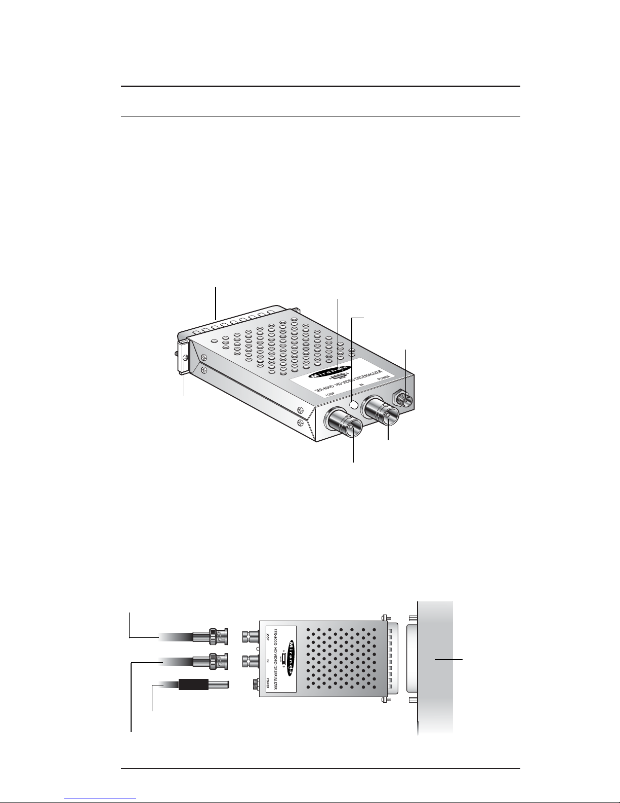
2.1 SER-800D Overview
Figure 2.1 illustrates the SER-800D’s major parts and their locations. The HD-SDI video input signal is connected to the IN BNC
connector and the decoded HD Parallel video signal is output
through the D-SUB 50 connector.
Figure 2.1 Overall View of the SER-800D
2.2 SER-800D Installation
To install the SER-800D directly on the destination equipment,
refer to the following diagram.
Figure 2.2 Connecting the SER-800D
2.3 SER-810E Overview
SER-800D/810E - Guide to Installation and Operation
3
Destination
HD-SDI
video
equipment
DC Power supply
Loop-through input
Loop-through BNC connector
Input BNC connector
Mode slide switch
Mounting screws
Status LED
DC power input connector
50-pin output connector
HD-SDI Input
Page 11
SER-800D/810 E - Guide to Installation and Operation
4
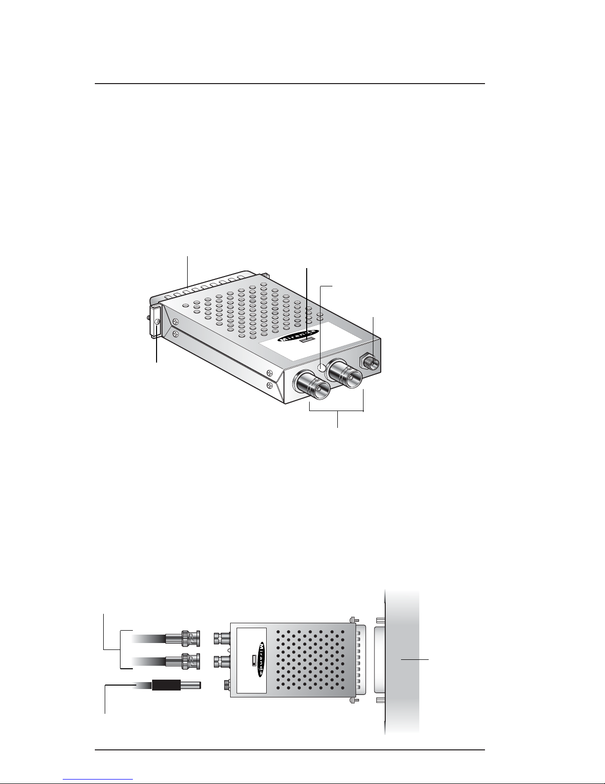
Figure 2.1 illustrates the SER-810E’s major parts and their locations. The HD parallel video input signal is connected to the
male 50-pin connector and the encoded HD SDI video signal is
output through the two OUT BNCs.
Figure 2.3 Overall View of the SER-810E
2.4 SER-810E Installation
To install the SER-810E directly on the source equipment, refer
to the following diagram.
Figure 2.4 Connecting the SER-810E
O
U
T
1
O
U
T
2
S
T
A
T
U
S
P
O
W
E
R
AB
H
D
V
ID
E
O
S
E
R
IA
L
IZ
E
R
S
E
R
-
8
1
0
E
M
O
D
E
Output BNC connectors
Mode slide switch
Mounting screws
Status LED
DC power input connector
50-pin input connector
OUT 1
OUT2
STATUS
POWER
AB
HD VIDEO SERIALIZERSER-810E
MODE
Source
HD
Parallel
video
equipment
DC Power supply
HD-SDI Outputs
Page 12

SER-800D/810E - Guide to Installation and Operation
5
3 Operation
3.1 Powering Up
To power the SER-800D/810E coders, follow these steps.
1- Insert the power plug from the power supply into the coder's
power jack.
2- Plug the DC power supply to an AC outlet.
3.2 SER-800D Operation
HD-SDI Video Video Input
Connect a HD serial digital video signal to the IN BNC input connector. The input must conform to SMPTE 292M (1.485 and
1.485/1.001 Gbps).
Parallel HD Output
The decoded HD parallel video signal is output by the D-SUB 50
connector. You can attach the SER-800D directly to the destination equipment by securing the mounting screws to the destination equipment female connector.
The output conforms to SMPTE-260M (for 1035i format), 296M
(for 720p format), 274M and 295M (for 1080sF, 1080i and 1080p
formats).
3.3 SER-810E Operation
Parallel HD Video Input
Connect a HD parallel video signal to the male 50-pin input connector. You can attach the SER-810E directly to the source
equipment by securing the mounting screws to the source equipment female connector.
The SER-810E accepts all popular 720p (SMPTE-296M),
1080sF, 1080i, 1080p (SMPTE-274M, and 295M) and 1035i
(SMPTE-260M) standards.
Page 13
HD-SDI Video Output (2)
The two HD SDI video signals are output by the two OUT BNCs
connectors. The output conforms to SMPTE 292M (1.485 and
1.485 /1.001 Gbps).
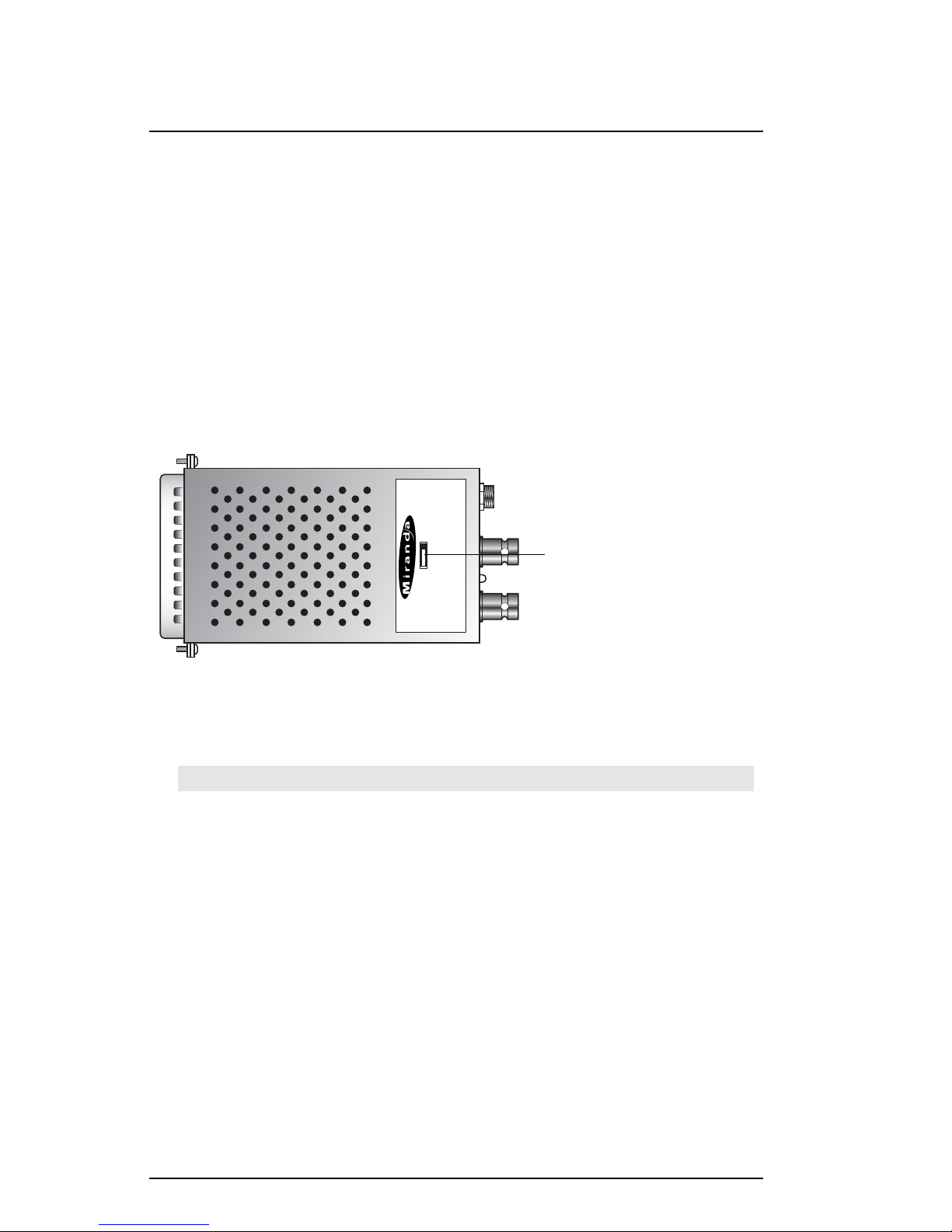
3.4 Mode Selection
Figure 3.1 indicates the location of the miniature slide switch on
the SER-800D/810E.
Figure 3.1 SER-800D/810E Slide Switch location
Mode A (Panasonic pinout)
Set the SER-800D/810E to this mode when connecting to equipment that uses the Panasonic D-SUB 50 pin-out:
SER-800D/810E - Guide to Installation and Operation
6
Pin # Signal* Pin# Signal* Pin# Signal*
1 CLK+ 34 CLK2 Data9+ 18 Data1+ 35 Data93 Data8+ 19 Data1- 36 Data84 Data7+ 20 Data0+ 37 Data75 Data6+ 21 Data0- 38 Data66 Data5+ 22 GND 39 Data57 Data4+ 23 GND 40 Data48 Data3+ 24 GND 41 Data39 Data2+ 25 GND 42 Data210 Data19+ 26 Data11+ 43 Data1911 Data18+ 27 Data11- 44 Data1812 Data17+ 28 Data10+ 45 Data1713 Data16+ 29 Data10- 46 Data1614 Data15+ 30 GND 47 Data1515 Data14+ 31 GND 48 Data1416 Data13+ 32 GND 49 Data1317 Data12+ 33 GND 50 Data12-
OUT 1
OUT2
STATUS
POWER
AB
HD VIDEO SERIALIZERSER-810E
MODE
Mode slide switch
Page 14

SER-800D/810E - Guide to Installation and Operation
7
Mode B (Philips pinout)
Set the SER-800D/810E to this mode when connecting to equipment that uses the Philips D-SUB 50 pin-out:
*
Note: All signals are of differential input/output type.
- Luminance channels are represented by Data0 thru Data9 for 10-bit
systems, and Data2 thru Data9 for 8-bit systerms.
- Chrominance channels are represented by Data10 thru Data19 for
10-bit systems, and Data12 thru Data19 for 8-bit systems.
3.5 Status LED
The bi-colored status LED, located next to the SER-800D input
connector or the SER-810E output connectors, is provided to
identify any input error or power supply malfunction. The following lists the possible situations:
Green: Indicates that the SER-800D/810E is powered and has
detected a valid HD parallel video input signal.
Red: Indicates an error with the input signal has been
detected or simply, there is no input cable connected.
Off: The unit is not powered on. Check that it is connected
to the power supply, and the power supply is properly
connected to a power source.
Pin # Signal* Pin# Signal* Pin# Signal*
1 CLK+ 34 CLK2 Data9+ 18 GND 35 Data93 Data8+ 19 GND 36 Data84 Data7+ 20 Data1+ 37 Data75 Data6+ 21 Data1- 38 Data66 Data5+ 22 Data0+ 39 Data57 Data4+ 23 Data0- 40 Data48 Data3+ 24 GND 41 Data39 Data2+ 25 GND 42 Data210 Data19+ 26 GND 43 Data1911 Data18+ 27 GND 44 Data1812 Data17+ 28 Data11+ 45 Data1713 Data16+ 29 Data11- 46 Data1614 Data15+ 30 Data10+ 47 Data1515 Data14+ 31 Data10- 48 Data1416 Data13+ 32 GND 49 Data1317 Data12+ 33 GND 50 Data12-
Page 15

SER-800D/810E - Guide to Installation and Operation
8
Page 16

SER-800D/810E - Guide to Installation and Operation
9
4 SER Accessories
4.1 SER-WSU Power Supply
The power supply SER-WSU, for 110V and 220V operation, is
used to power the SER-800D/810E. The SER-WSU provides a
regulated -5.1VDC@2.4A power source. Plug the power supply
into a wall or power bar outlet. The SER-WSU comes with two
outlet adapters; install the proper adapter for your area.
4.2 SER-CPS Centralized Power Supply Frame
Miranda's SER-CPS Centralized Power Supply Frame can power
up to 10 SER coders. A male-to-male power plug connector is
used for the connection between an SER coder and a DC output
jack. Refer to figure 4.1, DC Power connector pinout for the proper pinout.
Figure 4.1 DC Power connector pinout
-5.1VDC
Ground: digital and earth
grounds connected together
Plug specifications:
Inside diameter: 2.5 mm
Outside diameter: 5.5 mm
Minimum required shaft length: 10 mm
Warning: Damage will occur to unit if power supply adapter
polarities are not respected
Page 17

SER-800D/810E - Guide to Installation and Operation
10
4.2.1 SER-CPS Front Panel
Figure 4.2 describes the SER-CPS front panel.
Figure 4.2 SER-CPS Front Panel
The front panel consists of the following parts:
Power On Indicator
This indicator lights up when AC power is connected to the frame.
Power Fail Indicator
Flashes continuously when one of the frame's internal power
supplies becomes defective. The redundant power supply takes
control during this time.
Rack Mount Holes
Four rack mount holes are available for rack mounting.
4.2.2 SER-CPS Rear Panel
Figure 4.3 describes the SER-CPS back panel.
Figure 4.3 SER-CPS Rear Panel
SER Power Frame
POWER FAILPOWER ON
Rack mount holes Power On indicator Power Fail indicator
Air vents
10 DC outputs @ -5V AC power receptacle
Page 18

SER-800D/810E - Guide to Installation and Operation
11
The rear panel consists of the following parts:
DC Power Outputs
Ten DC power outputs are available to power any member of the
SER coder family.
AC Power Connector
AC power cord to be connected here. Both 110 VAC and 220
VAC standards supported.
Air Vents
Keep free from obstruction in order to maintain proper ventilation.
4.2.3 Installation
Figure 4.4 describes a typical SER-CPS installation.
Figure 4.4 SER-CPS Connections
OUT 1
OUT2
STATUS
POWER
AB
HD VIDEO SERIALIZERSER-800E
MODE
OUT 1
OUT2
STATUS
POWER
AB
HD VIDEO SERIALIZERSER-800E
MODE
OUT 1
OUT2
STATUS
POWER
AB
HD VIDEO SERIALIZERSER-800E
MODE
SER-CPS
top view
to 110/220 VAC
DC outputs
Page 19

SER-800D/810 E - Guide to Installation and Operation
12
4.2.4 Locating and replacing a defective power supply
In the event that the Power Fail indicator turns on, follow the
steps below to locate and replace the defective power supply:
1- Ensure that the SER-CPS is powered. Remove the top
cover, preventing contact with any internal AC wiring.
2- On the internal distribution board are 3 red LEDs. Each
LED is associated with a particular power supply. A flashing
LED indicates its designated power supply is defective. Use
the following diagram to locate the defective power supply.
3- Once the defective power supply has been located, unplug
the unit.
4- Remove the cable that connects to the defective power supply.
5- Remove the four screws that attach the power supply to the
frame.
6- Replace the defective power supply with a new one and recon-
nect the cable.
7- Replace cover.
Figure 4.5 Failed Power Supply Location
Power supply 1
LED for power
supply 1
LED for power
supply 2
LED for power
supply 3
Power supply 2
Power supply 3
Distribution board
SER-CPS top view, cover removed
Page 20

SER-800D/810E - Guide to Installation and Operation
13
4.3 DB-50 Cable Construction For Remote Installations
When direct mounting is not employed, use a DB-SUB 50 parallel cable. The DB-SUB 50 connectors should have #4-40 screw
locks with a conductive backshell to maintain proper shielding. If
the connector end installed on the SER-800D/810E coder is
male, use the female-to-female cable adapter provided. For
cables longer than a few meters, twisted pairs should be used for
each signal and its return.
Make sure to connect both ends of the cable in a pin-to-pin format (connect pin 1 of source connector to pin 1 of destination
connector, pin 2 to pin 2, ..., pin 50 to pin 50). For a detail of the
connector pinout, see the Panasonic D-SUB 50 pinout and the
Philips D-SUB 50 pinouts in section 3.4 Mode Selection.
Page 21

SER-800D/810E - Guide to Installation and Operation
14
Page 22

SER-800D/810E - Guide to Installation and Operation
15
5 Specifications
Inputs
SER-800D
HD-SDI video signal: HD-SDI (SMPTE-292M, 1.485 and
1.485/1.001 Gb/S) with active loop-
through
Max. cable length: 100m (350’)
Connector: BNC (75 ohm)
SER-810E
HD parallel video signal:
720p @ 23.98/24/25/29/29.97/30/50/59.94/60 Hz
frame freq. (SMPTE-296M)
1035i @ 59.94/60 Hz field freq. (SMPTE-260M)
1080sF @ 23.98/24 Hz frame freq. (SMPTE-274M)
1080p @ 23.98/24/25/29/29.97/30 Hz frame freq.
(SMPTE-274M)
1080i @ 50/59.94/60 Hz field freq. (SMPTE-274M
and 295M)
Max. cable length: 2 m (6’)
Connector: D-SUB 50
Panasonic or Philips pin-out, userselectable
Outputs
SER-800D
HD parallel video signal:
720p @ 23.98/24/25/29/29.97/30/50/59.94/60 Hz
frame freq. (SMPTE-296M)
1035i @ 59.94/60 Hz field freq. (SMPTE-260M)
1080sF @ 23.98/24 Hz frame freq. (SMPTE-274M)
1080p @ 23.98/24/25/29/29.97/30 Hz frame freq.
(SMPTE-274M)
1080i @ 50/59.94/60 Hz field freq. (SMPTE-274M
and 295M)
Page 23

SER-800D/810E - Guide to Installation and Operation
16
Connector: D-SUB 50
Panasonic or Philips pin-out, userselectable
SER-810E
HD SDI video signal (2): HD SDI (SMPTE-292M, 1.485 and
1.485/1.001 Gbps)
Connector: BNC (75 ohm)
Mechanical
Dimensions:
Width: 67mm (2.63")
Height: 20 mm (0.8")
Depth: 85 mm (3.35")
Weight: 140g (5oz)
SER-WSU Power Supply (regulated)
Voltage: -5.1VDC +0.1VDC
Max. Current: 2.4 A
Max. Ripple: 50mV
Connector: 2.5mm / 5.5mm Plug
SER-CPS Power Supply
Voltage: 85-264VAC/47-400Hz
Max. Power: 60W
Dimensions:
Width: 483mm (19")
Height: 1 RU
Depth: 175mm (6.9")
Weight: 4kg (8.8lbs)
NOTE: All specifications are subject to change without notification.
Page 24

Miranda
Technologies inc.
3499 Douglas-B.-Floreani
St-Laurent, Québec, Canada H4S 1Y6
Tel. 514-333-1772
Fax. 514-333-9828
www.miranda.com
Copyright 2002
Miranda Technologies Inc.
Specifications may be subject to change.
Printed in Canada
August 2002
SER -800D/E
SER-800D/E
Page 25

SER-800D/E - Guide to Installation and Operation
i
Warranty Policies
Warranty Statement
Miranda Technologies Inc. warrants that the equipment it manufactures shall be free
from defects in material and workmanship for a period of two (2) years from the date
of shipment from the factory. If equipment fails due to such defects, Miranda
Technologies Inc. will, at its option, repair or provide a replacement for the defective
part or product. Equipment that fails after the warranty period, has been operated or
installed in a manner other than that specified by Miranda, or has been subjected to
abuse or modification, will be repaired for time and material charges at the Buyer's
expense.
All out-of-warranty repairs are warranted for a period of ninety (90) days from the
date of shipment from the factory.
Miranda Technologies Inc. makes no other warranties, expressed or implied, of merchantability, fitness for a particular purpose or otherwise. Miranda's liability for any
cause, including breach of contract, breach of warranty, or negligence, with respect
to products sold by it, is limited to repair or replacement by Miranda, at its sole discretion. In no event shall Miranda Technologies Inc. be liable for any incidental or
consequential damages, including loss of profits.
Effective January 1, 2002
Warranty Exchange Policies
Miranda Technologies Inc. warrants that the equipment it manufactures shall be free
from defects in materials and workmanship for a period of two (2) years from the date
of shipment from the factory. If equipment fails due to such defects, Miranda will provide repair of the failed unit under the terms of the Miranda warranty.
If the equipment has been proven to be defective on arrival, Miranda will ship a new
product in exchange, usually within 36 hours of factory notification.
If the equipment to be repaired is essential and the customer so requests, Miranda
will, at its option, provide a service replacement or loaner part or product, usually
within 36 hours of factory notification, weekends and holidays excluded.
All warranty exchange or loaner parts or products shall be shipped to the Buyer with
a packing list clearly describing the items and stating the date of shipment. Repaired
parts or products will be shipped to the Buyer with a similar packing list. In the case
of exchange, the defective products or parts must be returned to Miranda within fifteen (15) days from receipt by the customer of the exchange product. In the case of
a loaner, the loaned products or parts must be returned to Miranda within fifteen (15)
days from receipt by the customer of the repaired equipment.
If the equipment is not returned within fifteen (15) days, as described for either
exchanges or loans, A Rental Invoice will be generated. Rental terms will be fifteen
(15) percent of the current list price of the products or parts per month or a fraction
thereof. Before returning the equipment to Miranda Technologies Inc., for any reason, the Buyer must first obtain a Return Authorization Number from Miranda
Technologies Inc. Miranda Technologies Inc will pay freight and insurance charges
Page 26

SER-800D/E - Guide to Installation and Operation
ii
for the delivery of the loaner or exchange products or parts. Freight and insurance
charges for the return of the defective product or part will also be paid by Miranda
Technologies.
Out-Of-Warranty Repair Policy
Miranda will repair equipment which is out of Warranty. The current pricing structure
for this service is available from the Miranda web site at www.miranda.com or from
Miranda Technical Support Services at (514) 333-1772. All out-of-warranty repairs
are warranted for a period of 90 days from the date of shipment from the factory.
Before returning the equipment to Miranda Technologies Inc., for any reason, the
Buyer must first obtain a Return Authorization Number from Miranda Technologies
Inc. In the case of a product deemed by Miranda to be beyond repair, the customer
must purchase a new product at current retail prices.
The Buyer will pay freight and insurance charges for the return of the defective product or part to the manufacturer for repair. Miranda Technologies will pay freight and
insurance charges for the return of the repaired product or part to the Buyer.
Out-Of Warranty Equipment Updates and Spare Parts Policy
Miranda Technologies' current pricing structure for out-of-warranty equipment
updates, or the sale of spare parts, is available from Miranda Technical Support
Services at (514) 333-1772.
Radio Frequency Interference and Immunity
This unit generates, uses, and can radiate radio frequency energy. If the unit
is not properly installed and used in accordance with this guide, it may cause
interference with radio communications. Operation with non-certified peripheral devices is likely to result in interference with radio and television reception. This equipment has been tested and complies with the limits in accordance with the specifications in:
- FCC Part 15, Subpart B
- CE EN50081-1:1992
- CE EN50082-1:1992.
Page 27

SER-800D/E - Guide to Installation and Operation
iii
How to contact us:
Head Office Miranda Europe
Miranda Technologies Inc. 222, 226 Rue De Rosny
3499 Douglas-B.-Floreani 93100 Montreuil
St. Laurent (Montreal), Que. H4S 1Y6 France
Canada
Tel +1 (514) 333-1772 +33 1 55 86 87 88
Fax +1 (514) 333-6914 +33 1 55 86 00 29
Toll free: 1-800-224-9828
www.miranda.com
Miranda Asia
Mita Nexus Bldg. 2F
1-3-33 Mita, Minato-Ku
Tokyo, Japan 108-0073
+81 3 5730 2988
+81 3 5730 2973
Page 28

SER-800D/E - Guide to Installation and Operation
iv
Page 29

SER-800D/E - Guide to Installation and Operation
v
Contents
page
1 SER-800D/E HD Video Deserializer/Serializer............ 1
1.1 Introduction............................................................... 1
1.2 Features....................................................................1
1.3 Unpacking.................................................................1
2 Installation...................................................................... 3
2.1 SER-800D Overview................................................. 3
2.2 SER-800D Installation...............................................3
2.3 SER-800E Overview................................................. 4
2.3 SER-800E Installation...............................................4
3 Operation........................................................................ 5
3.1 Powering Up............................................................. 5
3.2 SER-800D Operation................................................5
3.2 SER-800E Operation................................................5
3.4 Mode Selection.........................................................6
3.5 Status LED................................................................7
4 SER Accessories.......................................................... 9
4.1 SER-WSU Power Supply.......................................... 9
4.2 SER-CPS Centralized Power Supply Frame............9
4.2.1 SER-CPS Front Panel................................... 10
4.2.2 SER-CPS Rear Panel....................................10
4.2.3 Installation...................................................... 11
4.2.4 Locating and replacing a defective power
supply............................................................ 12
4.3 DB-50 Cable Construction for remote installation..... 13
5 Specifications.............................................................. 15
Page 30

SER-800D/E - Guide to Installation and Operation
vi
Page 31

SER-800D/E - Guide to Installation and Operation
1
1 SER-800D/E HD Video Deserializer/Serializer
1.1 Introduction
Part of Miranda's family of SER serial coders are the SER-800D
High Definition Video Deserializer and the SER-800E High
Definition Video Serializer. The SER-800D converts HD serial
digital video to HD parallel video, while the SER-800E converts
HD parallel video to HD serial digital video. Refer to section on
specifications for accepted digital video standards.
1.2 Features
- Compact HD Parallel to Serial/Serial to Parallel conversion
- Plugs directly into D-SUB 50 parallel connector of source
equipment
- Powered by wall plug-in or rack-mounted SER-CPS for up to
10 coders
- Automatic format detection
- 2 serial HD SDI outputs (SER-800D)
- Supports the following formats:
-720p @23.98/24/25/29/29.97/30/50/59.94/60 Hz frame freq.
-1035i @59.94/60 Hz field freq.
-1080sF@23.98/24 Hz frame freq.
-1080p @23.98/24/25/29/29.97/30 Hz frame freq.
-1080i @50/59.94/60 Hz field freq.
1.3 Unpacking
Make sure the following items have been shipped with your SER800D or SER-800E. If any of the following items are missing,
contact your distributor or Miranda Technologies Inc.
- SER-800D/E
- This manual
- A female-to-female D-SUB 50 cable adapter
To operate, the SER-800D/E requires either a wall plug-in power
supply - SER-WSU (110/220V) - or a centralized power supply
when up to 10 coders are used (SER-CPS).
Page 32

SER-800D/E - Guide to Installation and Operation
2
Page 33

2 Installation
2.1 SER-800D Overview
Figure 2.1 illustrates the SER-800D major parts and their locations. The HD-SDI video input signal is connected to the IN BNC
connector and the decoded HD Parallel video signal is output
through the D-SUB 50 connector.
Figure 2.1 Overall View of the SER-800D
2.2 SER-800D Installation
To install the SER-800D directly on the destination equipment,
refer to the following diagram.
Figure 2.2 Connecting the SER-800D
SER-800D/E - Guide to Installation and Operation
3
Loop-through BNC connector
Input BNC connector
Mode slide switch
Mounting screws
Status LED
DC power input connector
50-pin output connector
Destination
HD-SDI
video
equipment
DC Power supply
Loop-through input
HD-SDI Input
Page 34

SER-800D/E - Guide to Installation and Operation
4
2.3 SER-800E Overview
Figure 2.1 illustrates the SER-800E major parts and their locations. The HD parallel video input signal is connected to the
male 50-pin connector and the encoded HD SDI video signal is
output through the two OUT BNCs.
Figure 2.3 Overall View of the SER-800E
2.4 SER-800E Installation
To install the SER-800E directly on the source equipment, refer
to the following diagram.
Figure 2.4 Connecting the SER-800E
OUT 1
OUT2
STATUS
POWER
AB
HD VIDEO SERIALIZERSER-800E
M
ODE
Output BNC connectors
Mode slide switch
Mounting screws
Status LED
DC power input connector
50-pin input connector
OUT 1
OUT2
STATUS
POWER
AB
HD VIDEO SERIALIZERSER-800E
MODE
Source
HD
Parallel
video
equipment
DC Power supply
HD-SDI Outputs
Page 35

SER-800D/E - Guide to Installation and Operation
5
3 Operation
3.1 Powering Up
To power the SER-800D/E coders, follow these steps.
1- Insert the power plug from the power supply into the coder's
power jack.
2- Plug the DC power supply to an AC outlet.
3.2 SER-800D Operation
HD-SDI Video Video Input
Connect a HD serial digital video signal to the IN BNC input connector. The input must conform to SMPTE 292M (1.485 and
1.485/1.001 Gbps).
Parallel HD Output
The decoded HD parallel video signal is output by the D-SUB 50
connector. You can attach the SER-800D directly to the destination equipment by securing the mounting screws to the destination equipment female connector.
The output conforms to SMPTE-260M (for 1035i format), 296M
(for 720p format), 274M and 295M (for 1080sF, 1080i and 1080p
formats).
3.3 SER-800E Operation
Parallel HD Video Input
Connect a HD parallel video signal to the male 50-pin input connector. You can attach the SER-800E directly to the source
equipment by securing the mounting screws to the source equipment female connector.
The SER-800E accepts all popular 720p (SMPTE-296M),
1080sF, 1080i, 1080p(SMPTE-274M, and 295M) and 1035i
(SMPTE-260M) standards.
Page 36

HD-SDI Video Output (2)
The two HD SDI video signals are output by the two OUT BNCs
connectors. The output conforms to SMPTE 292M (1.485 and
1.485 /1.001 Gbps).
3.4 Mode Selection
Figure 3.1 indicates the locations of the miniature slide switch on
the SER-800D/E.
Figure 3.1 SER-800D/E Slide Switch location
Mode A (Panasonic pinout)
Set the SER-800D/E to this mode when connecting to an equipment that uses Panasonic D-SUB 50 pin-out:
SER-800D/E - Guide to Installation and Operation
6
OUT 1
OUT2
STATUS
POWER
AB
HD VIDEO SERIALIZERSER-800E
MODE
Mode slide switch
Pin # Signal* Pin# Signal* Pin# Signal*
1 CLK+ 34 CLK2 Data9+ 18 Data1+ 35 Data93 Data8+ 19 Data1- 36 Data84 Data7+ 20 Data0+ 37 Data75 Data6+ 21 Data0- 38 Data66 Data5+ 22 GND 39 Data57 Data4+ 23 GND 40 Data48 Data3+ 24 GND 41 Data39 Data2+ 25 GND 42 Data210 Data19+ 26 Data11+ 43 Data1911 Data18+ 27 Data11- 44 Data1812 Data17+ 28 Data10+ 45 Data1713 Data16+ 29 Data10- 46 Data1614 Data15+ 30 GND 47 Data1515 Data14+ 31 GND 48 Data1416 Data13+ 32 GND 49 Data1317 Data12+ 33 GND 50 Data12-
Page 37

SER-800D/E - Guide to Installation and Operation
7
Mode B (Philips pinout)
Set the SER-800D/E to this mode when connecting to an equipment that uses Philips D-SUB 50 pin-out:
*
Note: All signals are of differential input/output type.
- Luminance channels are represented by Data0 thru Data9 for 10-bit
systems, and Data2 thru Data9 for 8-bit systerms.
- Chrominance channels are represented by Data10 thru Data19 for
10-bit systems, and Data12 thru Data19 for 8-bit systems.
3.5 Status LED
The bi-colored status LED, located next to the SER-800D input
connector or the SER-800E output connectors, is provided to
identify any input error or power supply malfunction. The following lists the possible situations:
Green: Indicates that the SER-800D/E is powered and has
detected a valid HD parallel video input signal.
Red: Indicates an error with the input signal has been
detected or simply, there is no input cable connected.
Off: The unit is not powered on. Check that it is connected
to the power supply, and the power supply is properly
connected to a power source.
Pin # Signal* Pin# Signal* Pin# Signal*
1 CLK+ 34 CLK2 Data9+ 18 GND 35 Data93 Data8+ 19 GND 36 Data84 Data7+ 20 Data1+ 37 Data75 Data6+ 21 Data1- 38 Data66 Data5+ 22 Data0+ 39 Data57 Data4+ 23 Data0- 40 Data48 Data3+ 24 GND 41 Data39 Data2+ 25 GND 42 Data210 Data19+ 26 GND 43 Data1911 Data18+ 27 GND 44 Data1812 Data17+ 28 Data11+ 45 Data1713 Data16+ 29 Data11- 46 Data1614 Data15+ 30 Data10+ 47 Data1515 Data14+ 31 Data10- 48 Data1416 Data13+ 32 GND 49 Data1317 Data12+ 33 GND 50 Data12-
Page 38

SER-800D/E - Guide to Installation and Operation
8
Page 39

SER-800D/E - Guide to Installation and Operation
9
4 SER Accessories
4.1 SER-WSU Power Supply
The power supply SER-WSU, for 110V and 220V operation, is
used to power the SER-800D/E. The SER-WSU provides a regulated -5.1VDC@2.4A power source. Plug the power supply into
a wall or power bar outlet. The SER-WSU comes with two outlet
adapters; install the proper adapter for your area.
4.2 SER-CPS Centralized Power Supply Frame
Miranda's SER-CPS Centralized Power Supply Frame can power
up to 10 SER coders. A male-to-male power plug connector is
used for the connection between an SER coder and a DC output
jack. Refer to figure 4.1, DC Power connector pinout for the proper pinout.
Figure 4.1 DC Power connector pinout
-5.1VDC
Ground: digital and earth
grounds connected together
Plug specifications:
Inside diameter: 2.5 mm
Outside diameter: 5.5 mm
Minimum required shaft length: 10 mm
Warning: Damage will occur to unit if power supply adapter
polarities are not respected
Page 40

SER-800D/E - Guide to Installation and Operation
10
4.2.1 SER-CPS Front Panel
Figure 4.2 describes the SER-CPS front panel.
Figure 4.2 SER-CPS Front Panel
The front panel consists of the following parts:
Power On Indicator
This indicator lights up when AC power is connected to the frame.
Power Fail Indicator
Flashes continuously when one of the frame's internal power
supplies becomes defective. The redundant power supply takes
control during this time.
Rack Mount Holes
Four rack mount holes are available for rack mounting.
4.2.2 SER-CPS Rear Panel
Figure 4.3 describes the SER-CPS back panel.
Figure 4.3 SER-CPS Rear Panel
SER Power Frame
POWER FAILPOWER ON
Rack mount holes Power On indicator Power Fail indicator
Air vents
10 DC outputs @ -5V AC power receptacle
Page 41

SER-800D/E - Guide to Installation and Operation
11
The rear panel consists of the following parts:
DC Power Outputs
Ten DC power outputs are available to power any member of the
SER coder family.
AC Power Connector
AC power cord to be connected here. Both 110 VAC and 220
VAC standards supported.
Air Vents
Keep free from any object in order to maintain proper ventilation.
4.2.3 Installation
Figure 4.4 describes a typical SER-CPS installation.
Figure 4.4 SER-CPS Connections
OUT 1
OUT2
STATUS
POWER
AB
HD VIDEO SERIALIZERSER-800E
MODE
OUT 1
OUT2
STATUS
POWER
AB
HD VIDEO SERIALIZERSER-800E
MODE
OUT 1
OUT2
STATUS
POWER
AB
HD VIDEO SERIALIZERSER-800E
MODE
SER-CPS
top view
to 110/220 VAC
DC outputs
Page 42

SER-800D/E - Guide to Installation and Operation
12
4.2.4 Locating and replacing a defective power supply
In the event where the Power Fail indicator turns on, follow the
steps below to locate and replace the defective power supply:
1- Ensure that the SER-CPS is powered. Remove the top
cover, preventing contact with any internal AC wiring.
2- On the internal distribution board are 3 red LEDs. Each
LED is associated with a particular power supply. A flashing
LED indicates its designated power supply is defective. Use
the following diagram to locate the defective power supply.
3- Once the defective power supply has been located, unplug
the unit.
4- Remove the cable that connects to the defective power supply.
5- Remove the four screws that attach the power supply to the
frame.
6- Replace the defective power supply by a new one and recon-
nect the cable.
7- Replace cover.
Figure 4.5 Failed Power Supply Location
Power supply 1
LED for power
supply 1
LED for power
supply 2
LED for power
supply 3
Power supply 2
Power supply 3
Distribution board
SER-CPS top view, cover removed
Page 43

SER-800D/E - Guide to Installation and Operation
13
4.3 DB-50 Cable Construction For Remote Installations
When direct mounting is not employed, use a DB-SUB 50 parallel cable. The DB-SUB 50 connectors should have #4-40 screw
locks with a conductive backshell to maintain proper shielding. If
the connector end installed on the SER-800D/E coder is male,
use the female-to-female cable adapter provided. For cables
longer than a few meters, twisted pairs should be used for each
signal and its return.
Make sure to connect both ends of the cable in a pin-to-pin format (connect pin 1 of source connector to pin 1 of destination
connector, pin 2 to pin 2, ..., pin 50 to pin 50). For a detail of the
connector pinout, see the Panasonic D-SUB 50 pinout and the
Philips D-SUB 50 pinouts in section 3.4 Mode Selection.
Page 44

SER-800D/E - Guide to Installation and Operation
14
Page 45

SER-800D/E - Guide to Installation and Operation
15
5 Specifications
Inputs
SER-800D
HD-SDI video signal: HD-SDI (SMPTE-292M, 1.485 and
1.485/1.001 Gb/S) with active loop-
through
Max. cable length: 100m (350’)
Connector: BNC (75 ohm)
SER-800E
HD parallel video signal:
720p @ 23.98/24/25/29/29.97/30/50/59.94/60 Hz
frame freq. (SMPTE-296M)
1035i @ 59.94/60 Hz field freq. (SMPTE-260M)
1080sF @ 23.98/24 Hz frame freq. (SMPTE-274M)
1080p @ 23.98/24/25/29/29.97/30 Hz frame freq.
(SMPTE-274M)
1080i @ 50/59.94/60 Hz field freq. (SMPTE-274M
and 295M)
Max. cable length: 2 m (6’)
Connector: D-SUB 50
Panasonic or Philips pin-out, userselectable
Outputs
SER-800D
HD parallel video signal:
720p @ 23.98/24/25/29/29.97/30/50/59.94/60 Hz
frame freq. (SMPTE-296M)
1035i @ 59.94/60 Hz field freq. (SMPTE-260M)
1080sF @ 23.98/24 Hz frame freq. (SMPTE-274M)
1080p @ 23.98/24/25/29/29.97/30 Hz frame freq.
(SMPTE-274M)
1080i @ 50/59.94/60 Hz field freq. (SMPTE-274M
and 295M)
Page 46

SER-800D/E - Guide to Installation and Operation
16
Connector: D-SUB 50
Panasonic or Philips pin-out, userselectable
SER-800E
HD SDI video signal (2): HD SDI (SMPTE-292M, 1.485 and
1.485/1.001 Gbps)
Connector: BNC (75 ohm)
Mechanical
Dimensions:
Width: 67mm (2.63")
Height: 20 mm (0.8")
Depth: 85 mm (3.35")
Weight: 140g (5oz)
SER-WSU Power Supply (regulated)
Voltage: -5.1VDC +0.1VDC
Max. Current: 2.4 A
Max. Ripple: 50mV
Connector: 2.5mm / 5.5mm Plug
SER-CPS Power Supply
Voltage: 85-264VAC/47-400Hz
Max. Power: 60W
Dimensions:
Width: 483mm (19")
Height: 1 RU
Depth: 175mm (6.9")
Weight: 4kg (8.8lbs)
NOTE: All specifications are subject to change without notification.
 Loading...