

Page 1

picoLink series
SDM-874p
SD/HD Serial Digital
to DVI Converter
Guide to Installation and Operation
M804-9900-103
8 Sep 2008
Miranda
Technologies Inc.
3499 Douglas-B.-Floreani
St-Laurent, Québec, Canada H4S 1Y6
Tel. 514-333-1772
Fax. 514-333-9828
www.miranda.com
© 2008 Miranda Technologies I
Page 2

GUIDE TO INSTALLATION AND OPERATION
SDM-874p
Radio Frequency Interference and Immunity
This unit generates, uses and can radiate radio frequency
energy. If the unit is not properly installed and used in
accordance with this guide, it may cause interference with radio
communications. Operation with non-certified periphe ral devicesi
likely to result in interference with radio and television reception.
This equipment has been tested and complies with the limits in
accordance with the specifications in:
FCC Part 15, Subpart B
CE EN50081-1:1992
CE EN50082-1:1992
Contact Miranda
For technical assistance, please contact the Miranda
Technical Support centre nearest you:
Americas
Telephone:
+1-800-224-7882
e-mail:
techsupp@miranda.com
Asia
Telephone:
+81-3-5730-2987
e-mail:
asiatech@miranda.com
China
Telephone:
+86-10-5873-1814
e-mail:
asiatech@miranda.com
Europe, Middle East, Africa, UK
Telephone:
+44 (0) 1491 820222
e-mail:
eurotech@miranda.com
France (only)
Telephone:
+33 (0) 1 55 86 87 88
e-mail:
eurotech@miranda.com
Visit our web site at www.miranda.com
Page 3

GUIDE TO INSTALLATION AND OPERATION
SDM-874p
Table of Contents
1 SDM-874p SD/HD Serial Digital to DVI Converter............ 1
1.1 Introduction........................................................................ 1
1.2 Features ............................................................................ 1
2 Overview .............................................................................. 2
3 Installation ........................................................................... 3
3.1 Power Supply .................................................................... 3
3.2 HD/SD Serial Digital Video Input & Active Loop-Through 4
3.3 RGB Output....................................................................... 4
4 Operation ............................................................................. 5
4.1 Slide Switch functions:......................................................5
4.2 Select Pushbutton functions:............................................. 6
4.3 Status LED........................................................................ 8
5 Specifications...................................................................... 9
Appendix – Supported Formats............................................. 10
Page 4

GUIDE TO INSTALLATION AND OPERATION
SDM-874p
Page 5
GUIDE TO INSTALLATION AND OPERATION
SDM-874p | 1
1 SDM-874p SD/HD Serial Digital to DVI Converter
1.1 Introduction
The SDM-874p is a miniature digital video interface, converting
SDI/HDSDI video signals to Digital RGB (DVI-HDTV). It provides
automatic input scan rate detection and supports a wide variety
of input formats, including 525i, 625i, 720p, 1080i and 1080p.
The primary application is to convert SD/HD serial digital video to
Digital RGB to feed DVI-HDTV displays and projectors (CRT,
LCD, Plasma, DLP, D-ILA, etc.). In order to support the
emerging popularity of 24p equipment and displays, the SDM874p outputs DVI-D with selectable 3:2 sequence insertion. The
SDM-874p is compatible with any 1280x768 or 1920x1200
native resolution display, including the Apple Cinema Display.
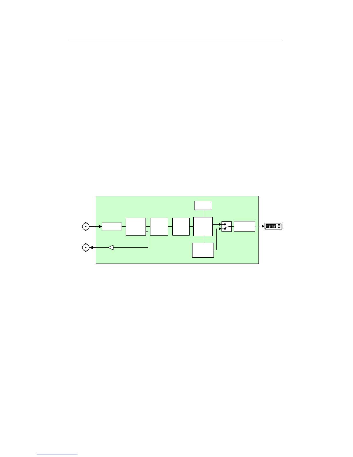
Equalizer
Color
Bar Gen
SDI /
HD-SDI
Color
Space
Converter
DVI
Serializer
Markers
4:3
Frame
Buffer
3:2,
Bypass
IN
1920x1200
1280x768
Mapper
SD / HD
Reclocker
DVI
LOOP
Figure 1: SDM-874p functional block diagram
1.2 Features
• SDI / HD SDI video input with active loop-through
• Digital RGB DVI-D output (DVI-HDTV compliant)
• Supports 525i, 625i, 720p, 1080p, 1080i with automatic
input scan rate detection
• Supports many processing modes (see the Input/Output
formats table on pages 10 & 11)
• 1920x1200 Apple HD Cinema display compatible
• Built-in test signal and 4:3 markers
• Compact stand-alone package
Page 6

GUIDE TO INSTALLATION AND OPERATION
2 | SDM-874p
2 Overview
Figure 2 illustrates the SDM-874p's major parts and their
locations. A high-definition or standard definition digital video
source is connected to the SDI/HD SDI IN BNC and the Digital
RGB output is provided by the DVI-I connector. Error status is
provided by the status LED. Finally, the power source is
connected to the lockable power connector.
Figure 2: Overall view of the SDM-874p
SDI/HDSDI input
Power connector
DVI-I RGB output
Loop-through
Status LED
Page 7

GUIDE TO INSTALLATION AND OPERATION
SDM-874p | 3
3 Installation
3.1 Power Supply
The LKS-WSU power supply provides power to the SDM-874p
for 110 V and 220 V operation. The power supply is a regulated
+5 VDC@2.4 A power source. The SDM-874p employs a mini
XLR-3 connector for its power needs. Figure 3 shows a detailed
pinout of the male connector.
13
2
(male connector-facing)
Pin 1: Shield
Pin 2: GND
Pin 3: +5 VDC
Figure 3: Power connector pinout
Page 8

GUIDE TO INSTALLATION AND OPERATION
4 | SDM-874p
3.2 HD/SD Serial Digital Video Input & Active LoopThrough
Connect a high-definition or standard definition digital video
signal to the BNC labeled SDI/HD-SDI IN:
• The high-definition serial digital input signal must conform
to the SMPTE 292M standard.
• The standard definition serial digital input signal must
conform to the SMPTE 259M-C standard.
Make sure that the input signal cable has a maximum length of
100m (328’) and that all serial digital video equipment is
connected point-to-point. For instance, there must be a point-topoint connection between the SDI/HD SDI IN BNC and the
source equipment. If a T-connector is used to connect other
equipment, the maximum specified cable length is no longer
valid.
3.3 RGB Output
The high definition DVI video output signal (RGB digital) is
provided by the DVI-I (female) labeled OUTPUT. The output
format is automatically selected according to the input signal
format and the user control settings.
For a complete list of the input and output formats supported by
the SDM-874p, see the Supported Formats table on pages 10 &
11.
Page 9

GUIDE TO INSTALLATION AND OPERATION
SDM-874p | 5
4 Operation
Figure 4 shows the control panel of the SDM-874p, indicating the
five slide switches, the Select pushbutton, and the LED
indicators that show the status established using the Select
pushbutton.
Figure 4: SDM-874p control panel
4.1 Slide Switch functions:
Test
On: Enable the te st pattern on the output. The test pattern
consists of HDTV color bars.
Off: The test pattern is disabled.
Note: in order to output a test pattern, a valid input signal must
be present.
Markers 4:3
On: Display 4:3 markers on the 16:9 image.
Off: The 4:3 ma rkers are disabled.
Page 10

GUIDE TO INSTALLATION AND OPERATION
6 | SDM-874p
DVI
STD: Video levels are maintained from the SD/HD SDI input
to the DVI output.
EXPD: Video levels from the SD/HD SDI input (16 to 235 in 8
bits) are expanded to the full graphic range (0 to 255 in
8 bits) at the DVI output.
TC
On: If time code is dete cted on the input, it will be burne d into
the output video. If no time code is detected, 00:00:00
will be displayed.
Off: The time code displ ay in the output video will be
disabled.
GFX
1920x1200: Select 1920x1200 as the resolution of the graphic
display output (GFX 60p and GFX 50p). The input
video (SD, 720, 1080) will be mapped into this
image structure.
1280x768: Select 1280x768 as the resolution of the graphic
display output (GFX 60p and GFX 50p). The input
video (SD, 720) will be mapped into this image
structure.
.
4.2 Select Pushbutton functions:
The Select pushbutton cycles the operation of the SDM-874p
through its available operating modes. The current operating
mode is indicated by the six LEDs located to the right of the
pushbutton, as shown in Figure 4. The six named modes are
selected when their LED only is illuminated. Modes A, B and C
are selected when the pair of LEDs indicated are illuminated.
Page 11

GUIDE TO INSTALLATION AND OPERATION
SDM-874p | 7
• When the pushbutton is pushed once, the LED indicating
the currently selected processing mode flashes red a nd
green. Subsequent pushes cycle the SDM-874p through
the available operating modes.
The available operating modes are:
• Mode A: direct output – the output signal format matches
the input format
• 60i: the output is forced to 60i
• 50i: the output is forced to 50i
• Mode B: reserved for future use
• 60p: the output is forced to 60p
• 50p: the output is forced to 50p
• Mode C: reserved for future use
• GFX 60p: the output is forced to the selected GFX output
resolution (1920x1200 or 1280x768) at 60p.
• GFX 50p: the output is forced to the selected GFX output
resolution (1920x1200 or 1280x768) at 50p.
The SDM-874p automatically detects the input format. It then
internally invokes the appropriate processing to produce the
result selected by the user controls. Among the processing
modes implemented in the SDM-874p are:
• Progressive Segmented Frame (PsF) video takes a
progressive source and divides the image into two fields
as if it had been an interlaced source. This video mimics
the interlaced format and can be processed accordingly.
The SDM-874p converts P→PsF and PsF→ P.
• The Panason i c Varicam system packages video originated
at various frame rates into a standard 59.94i or 60i output
by adding redundant frames. The original frames are
flagged, allowing the original frame-rate signal to be
reconstituted. The SDM-874p supports Varicam output
flagged at 60, 50, 25 and 24 fps.
Page 12

GUIDE TO INSTALLATION AND OPERATION
8 | SDM-874p
See the Supported Formats table on pages 10 and 11 for a
detailed list of the outputs corresponding to the supported input
formats and user control settings.
4.3 Status LED
The multi-colored status LED, located between the input and
loop-through connectors, identifies any input errors and the
selection of the test pattern as follows:
Green: Indicates the SDM-874p is powered and has
detected a valid input signal.
Red: Indicates an error in the input signal has been
detected or that there is no input signal installed.
Yellow: The test pattern is selected.
If an error is detected on the input signal when the test pattern is
selected, the status LED will remain red.
Page 13

GUIDE TO INSTALLATION AND OPERATION
SDM-874p | 9
5 Specifications
INPUT
Signal: SMPTE 259M-C (270Mbps) and
SMPTE 292M (1.485, 1.485/1.001 Gbps)
with re-clocked loop-through output
Cable length: 100 m (Belden 1694A)
Return loss: >15 dB up to 1.5 GHz
Connector: 75W BNC
OUTPUT
Normal mode: DVI output compliant to EIA/CEA-861-B
GFX mode DVI output compliant to VESA DMT
Connector: DVI-I, Female, compliant to DVI 1.0 pin out
GENERAL
Quantization: 10 bits
Power voltage: 5VDC
Consumption: 4 W
Temperature
operating range: 0 – 30° C
Page 14

GUIDE TO INSTALLATION AND OPERATION
10 | SDM-874p
Appendix – Supported Formats
Input format GFX Mode Output format
Switch Selected
525i - A 1440x486 59.94i
- 60p 720x486 59.94p
1920 GFX 60p 1920x1200 60p
1280 GFX 60p 1280x768 60p
625i - A 1440x576 50i
- 50p 720x576 50p
1920 GFX 50p 1920x1200 50p
1280 GFX 50p 1280x768 50p
1280x720 60p - A 1280x720 60p
1920 GFX 60p 1920x1200 60p
1280 GFX 60p 1280x768 60p
(Varicam / 24 fps) - 50p 1280x720 50p
1920 GFX 50p 1920x1200 50p
1280 GFX 50p 1280x768 50p
(Varicam / 25 fps) - 50p 1280x720 50p
1920 GFX 50p 1920x1200 50p
1280 GFX 50p 1280x768 50p
(Varicam / 50 fps) - 50p 1280x720 50p
1920 GFX 50p 1920x1200 50p
1280 GFX 50p 1280x768 50p
1280x720 50p - A 1280x720 50p
1920 GFX 50p 1920x1200 50p
1280 GFX 50p 1280x768 50p
1920x1080 60i - A 1920x1080 60i
- 60p 1920x1080 60p
1920 GFX 60p 1920x1200 60p
1920x1080 50i/25PsF - A 1920x1080 50i
- 50p 1920x1080 50p
1920 GFX 50p 1920x1200 50p
1920 GFX 60p 1920x1200 60p
Page 15

GUIDE TO INSTALLATION AND OPERATION
SDM-874p | 11
Supported Formats (continued)
Input format GFX Mode Output format
Switch Selected
1920x1080 24PsF - A 1920x1080 24PsF
- 60i 1920x1080 60i
- 60p 1920x1080 60p
1920 GFX 60p 1920x1200 60p
- 50i 1920x1080 25PsF
- 50p 1920x1080 50p
1920 GFX 50p 1920x1200 50p
1920x1080 25p - A 1920x1080 25p
- 50i 1920x1080 25PsF
- 50p 1920x1080 50p
1920 GFX 50p 1920x1200 50p
1920x1080 24p - A 1920x1080 24p
- 60i 1920x1080 60i
- 60p 1920x1080 60p
1920 GFX 60p 1920x1200 60p
- 50i 1920x1080 25PsF
- 50p 1920x1080 50p
1920 GFX 50p 1920x1200 50p
Note: in all cases where the format is specified as 24 or 60, the
specification also includes 23.98 and 59.94 when ap propriate.
For example, 1920x1080 60i should be understood to also refer
to 1920x1080 59.94i, and the output will follow the input, so that
an input at 23.98 will yield an output at 59.94, whereas an input
at 24 will yield an output at 60.
As an exception, 525i inputs are always at 59.94, and so the
normal mode outputs have been explicitly specified as 59.94.
However, the GFX outputs are specifically 60 in this case, and
have been so specified.
 Loading...