

Page 1
Page 2

SDM-872p
i
Radio Frequency Interference and Immunity
This unit generates, uses, and can radiate radio frequency energy. If the unit
is not properly installed and used in accordance with this guide, it may cause
interference with radio communications. Operation with non-certified peripheral devices is likely to result in interference with radio and television reception. This equipment has been tested and complies with the limits in accordance with the specifications in:
- FCC Part 15, Subpart B
- CE EN50081-1:1992
- CE EN50082-1:1992.
How to contact us:
CONTACT MIRANDA
For technical assistance, please contact the Miranda Technical Support centre nearest you:
Americas Asia
Telephone: Telephone:
+1-800-224-7882 +81-3-5730-2987
e-mail: e-mail:
techsupp@miranda.com asiatech@miranda.com
Europe, Middle East, Africa, UK France (only)
Telephone: Telephone:
+44 (0) 1491 820222 +33 (0) 1 55 86 87 88
e-mail: e-mail:
eurotech@miranda.com francetech@miranda.com
Visit our web site at www.miranda.com
Page 3

Guide to Installation and Operation
ii
Contents
page
1 SDM-872p SD/HD Serial Digital to DVI-HDTV
Converter
..................................................................... 1
1.1 Introduction............................................................... 1
1.2 Features....................................................................1
2 Overall View................................................................... 2
3 Installation...................................................................... 3
3.1 Power Supply............................................................ 3
3.2 HD/SD Serial Digital Video Input with Active Loop-
through..................................................................... 3
3.3 Digital RGB Video Output......................................... 4
4 Operation........................................................................ 5
4.1 Switch Settings......................................................... 5
4.2 Status LED............................................................... 7
5 Specifications................................................................ 8
Page 4

Page 5
Guide to Installation and Operation
1
1.0
SDM-872p SD/HD Serial Digital to DVI-HDTV Converter
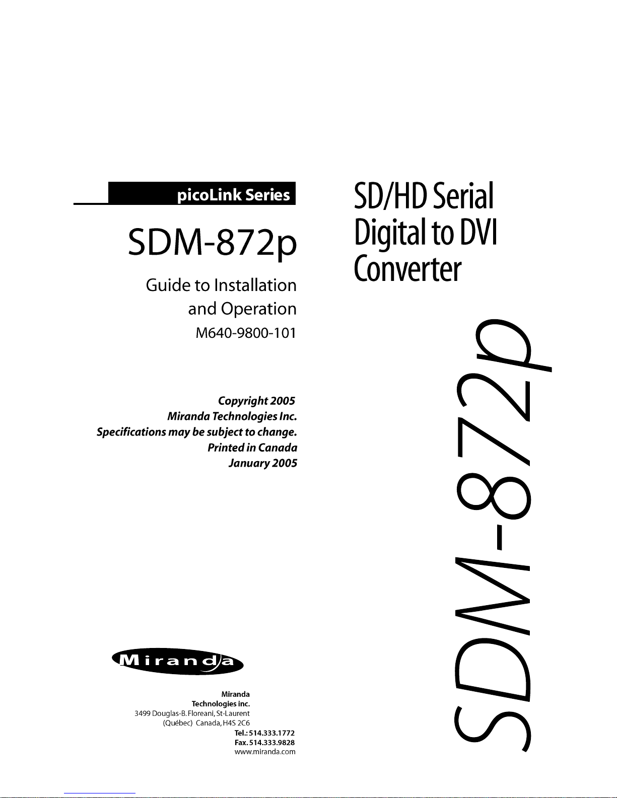
1.1 Introduction
The SDM-872p is a miniature, digital video interface converting
SDI and HDSDI video signal to Digital RGB (DVI-HDTV, DVISDTV) without resizing. The SDM-872p provides automatic input
scan rate detection and supports a wide variety of input formats
including 525i, 625i, 720p, 1080i and 1080p. Output formats are
compliant to EIA/CEA-861-B standard. The primary application is
to convert SD and HD serial to Digital RGB for the purposes of
feeding a computer monitor and projector. (CRT, LCD, Plasma,
DLP, D-ILA etc). In order to support the emerging popularity of
24p equipment and digital display, the SDM-872p DVI output with
selectable 3:2 sequence insertion.
Figure 1 SDM-872p functional block diagram
1.2 Features
- SDI and HD SDI video input with active loop-through
- Digital RGB output compliant to DVI 1.0
- Supports 525i, 625i, 720p, 1080p, 1080i with automatic input
scan rate detection
- Supports direct output, p to PsF, PsF to p, 3:2 insert,
Panasonic Varicam
- Built-in test signal and 4:3 markers
- Compact stand-alone package
DVI
SDI/
HD SDI
IN
LOOP
SD/HD
De-Serializer
Reclocker
Frame
Buffer
Color
Space
Converter
Equalizer
DVI
Serializer
Color bar
Generator
Page 6

SDM-872p
2
2.0 Overall View
Figure 2 illustrates the SDM-872p's major parts and their locations. A high-definition or standard definition digital video source
is connected to the HD/SD SDI IN BNC and the Digital RGB output is provided by the DVI-D connector. Error status is provided
by the status LED. Finally, the power source is connected to the
lockable power connector.
Figure 2 Overall view of the SDM-872p
Input BNC
Power connector
Status LED
Output DVI
Loop-through
BNC
Page 7

Guide to Installation and Operation
3
3.0 Installation
3.1 Power Supply
The power supplies LKS-WSU, for 110 V and 220 V operation, is
used to power the SDM-872p. The power supply provides a regulated +5 VDC@2.4 A power source. The SDM-872p employs
a mini XLR-3 connector for its power needs. Figure 3 provides a
detailed pinout of the male connector.
Figure 3 Power connector pinout
3.2 HD/SD Serial Digital Video Input with Active LoopThrough
Connect a high-definition or standard definition digital video signal to the BNC labeled HD-SDI IN. The high-definition serial digital input signal must conform to the SMPTE 292M standard.
The standard definition serial digital input signal must conform to
the SMPTE 259M-C standard.
Make sure that the input signal cable has a maximum length of
75m (250’) and that all serial digital video equipment are connected point-to-point. For instance, there must be a point-topoint connection between the HD/SD SDI IN BNC and the source
equipment. If a T-connector is used to connect other equipment,
the maximum specified cable length is no longer valid.
+5VDC
GND
Shield
Page 8

SDM-872p
4
3.3 Digital RGB Video Output
The digital RGB video output signal (DVI-HDTV) is provided by
the DVI-D (female) labeled OUTPUT. The output format is automatically selected according to the input signal; for a complete
list of the output formats and related SMPTE standards refer to
section 5 Specifications.
Page 9

Guide to Installation and Operation
5
4.0 Operation
4.1 Switch Settings
Figure 4.1 outlines the slide switches and pushbutton selection.
Figure 4.1 SDM-872p Underside
Slide Switches selection:
Test Pattern Selection
On: Set the “Test” slide switch to this position to enable
the test pattern on output. The test pattern consists
of a HDTV color bars.
Off: The test pattern is disabled.
Note: in order to output a test pattern, a valid input signal must
be installed.
Miranda Technologies Inc.
Made in Canada
SDM-872p
TEST
SELECT
DIRECT OUTPUT
A
MARKERS 4:3
INPUT FORMAT
OFF
ON
ON
I
PsF
OFF
3:2 INSERT
P -> PsF
PsF -> P
VARICAM 1:1
VARICAM 1:2
B
C
Page 10

SDM-872p
6
Markers 4:3 Selection:
On: Set the “Markers 4:3” slide switch to this position to
display 4:3 markers on the 16:9 image.
Off: The 4:3 markers are disabled.
Input format
I: Set the “Input Format” slide switch to this position
for most input signal.
PsF: Set the “Input Format” slide switch to this position
to access additional output format when input format
is 1920x1080 25PsF.
Pushbutton Selection
The “Select” pushbutton allows the selection of different processing modes, according to the input format. When the pushbutton
is depressed once, the LED indicating the currently selected processing mode flashes red and green; when depressed again, the
alternate option LED flashes in its turn if it is available. Confirm
the selection by depressing the pushbutton again. Other processing modes are accessed by depressing the pushbutton consecutively until the desired mode is reached. For processing
mode A, B and C, both LEDs need to be turned on. See the supported format table in section 5 Specification for details on
resulting outputs.
Mode A: use this mode to output 25PsF signal from a 24p or
24PsF input signal.
Direct output:
use this selection to output a signal with the same
format as the input signal.
3:2 Insert: inserts a 3:2 sequence to output a 59.94i and 60i signal.
Mode B: reserved for future use
P
→
PsF: use this selection to output an interlaced signal from
Page 11

Guide to Installation and Operation
7
a progressive input signal.
PsF
→
P: use this selection to output a progressive signal from
an interlaced input signal.
Mode C: reserved for future use
Varicam 1:1:
use this setting to output a 24p, 25p or 30p signal
from a 60p or 59.94p signal originating from a
Panasonic varicam system.
Varicam 1:2:
use this setting to output a 50p signal from a 60p
signal originating from a Panasonic varicam system.
4.2 Status LED
The multicolored status LED, located between the HD/SD SDI IN
and LOOP BNC connectors, is provided to identify any input
errors and the selection of the test pattern. The following lists all
possible situations.
Green: Indicates that the SDM-872p is powered and
has detected a valid input signal.
Red: Indicates an invalid input signal or simply, there
is no input signal installed.
Orange: The test pattern is selected.
Page 12

SDM-872p
8
5.0 Specifications
Input
Signal: SMPTE 292M (1.485, 1.485/1.001 Gbps)
with re-clocked loop-through output
Cable length: 75 m (250') (Belden 1694A)
Return loss: >15 dB up to 1.5 GHz
Connector: 75Ω BNC
Output
Signal: Digital fixed GBR (DVI)
Connector: DVI-D, Female, compliant to DVI 1.0 pin out
Digital format: DVI output format are compliant to EIA/CEA-
861-B except for:
1920x1080/24,23.98/PsF
Analog Format: Auto select based on input signal
See Supported Format Table
H/V Level: TTL Level
General specification
Processing delay: see Supported Format Table
Power voltage: 5VDC
Consumption: 4 W
Page 13

Guide to Installation and Operation
9
Supported Format
I
nput format Standard Mode VGA & DVI Standard Delay
output format
525 SMPTE-125M Dir.Output 720x486 59.94i SMPTE-125M < 5us
SMPTE-267M SMPTE-267M
625 EBU Dir.Output 720x576 50i EBU < 5us
1280x720 60p SMPTE-296M Dir.Output 1280x720 60p SMPTE-296M < 5us
Varicam 1:1 1280x720 24p SMPTE-296M 1 Fr.
Varicam 1:1 1280x720 25p SMPTE-296M 1 Fr.
Varicam 1:1 1280x720 30p SMPTE-296M 1 Fr.
Varicam 1:1 1280x720 50p SMPTE-296M 1 Fr.
Varicam 1:2 1280x720 50p SMPTE-296M 1 Fr.
1280x720 59.94p SMPTE-296M Dir.Output 1280x720 59.94p SMPTE-296M < 5us
Varicam 1:1 1280x720 23.98p SMPTE-296M 1 Fr.
Varicam 1:1 1280x720 29.97p SMPTE-296M 1 Fr.
Varicam 1:1 1280x720 49.95p SMPTE-296M 1 Fr.
Varicam 1:2 1280x720 49.95p SMPTE-296M 1 Fr.
1280x720 50p SMPTE-296M Dir.Output 1280x720 50p SMPTE-296M < 5us
1920x1080 60i SMPTE-274M Dir.Output 1920x1080 60i SMPTE-274M < 5us
1920x1080 59.94i SMPTE-274M Dir.Output 1920x1080 59.94i SMPTE-274M < 5us
1920x1080 50i SMPTE-274M Dir.Output 1920x1080 50i SMPTE-274M < 5us
1920x1080 25 PsF SMPTE-274M Dir.Output 1920x1080 25 PsF* SMPTE-274M < 5us
PsF
→
P 1920x1080 25p* SMPTE-274M 1 Fr.
1920x1080 24 PsF SMPTE-274M Dir.Output 1920x1080 24 PsF SMPTE-274M < 5us
PsF
→
P 1920x1080 24p SMPTE-274M 1 Fr.
3:2 Insert 1920x1080 60i SMPTE-274M 1 Fr.
A 1920x1080 25 PsF* SMPTE-274M 1 Fr.
1920x1080 23.98PsF SMPTE-274M Dir.Output 1920x1080 23.98 PsF SMPTE-274M < 5us
PsF
→
P 1920x1080 23.98p SMPTE-274M 1 Fr.
3:2 Insert 1920x1080 59.94i SMPTE-274M 1 Fr.
A 1920x1080 24.97 PsF 1 Fr.
1920x1080 25p SMPTE-274M Dir.Output 1920x1080 25p* SMPTE-274M < 5us
P
→
PsF 1920x1080 25 PsF* SMPTE-274M 1 Fr
Page 14

SDM-872p
10
1920x1080 24p SMPTE-274M Dir.Output 1920x1080 24p SMPTE-274M < 5us
P→PsF 1920x1080 24 PsF SMPTE-274M 1 Fr.
3:2 Insert 1920x1080 60i SMPTE-274M 1 Fr.
A 1920x1080 25 PsF* SMPTE-274M 1 Fr.
1920x1080 23.98p SMPTE-274M Dir. Output 1920x1080 23.98p SMPTE-274M < 5us
P
→
PsF 1920x1080 23.98 PsF SMPTE-274M 1 Fr.
3:2 Insert 1920x1080 59.94i SMPTE-274M 1 Fr.
* Not yet tested
 Loading...