

Page 1

Imagestore HDTV
User Manual
02901-02
Dec-2002
Miranda Technologies Ltd.
Hithercroft Road
Wallingford
Oxfordshire, OX10 9DG,
UK
Tel: +44 (0) 1491 820000
Fax: +44 (0) 1491 820001
Email: uksales@miranda.com
Web: www.miranda.com
Page 2

Preface Imagestore HDTV User Manual
Copyright © 1999 - 2002 Miranda Technologies Ltd. All rights are reserved
and, under the copyright laws, this manual may not be reproduced in any
form, in whole or in part, without the prior written consent of Miranda
Technologies Ltd.
Printed in the UK.
Miranda Technologies Ltd.
Hithercroft Rd.
Wallingford,
Oxfordshire. OX10 9DG.
Page 2 Miranda Technologies Ltd
Page 3

Imagestore HDTV User Manual Preface
Preface
Warranty
Miranda Technologies Ltd offer a 24 months free parts and labour warranty
on Oxtel Series equipment from the date of the initial invoice, providing
there is no evidence of negligence, abuse or failure to reasonably follow
instructions given by the Company for its proper use.
During the warranty period, Miranda Technologies Ltd will replace or repair
at its cost, Oxtel Series equipment returned to the factory, carriage and duty
paid and insured by the sender.
Before returning any item for warranty repair, a valid returns authorisation
must be granted by Miranda Technologies Ltd.
All repaired goods will be delivered (as instructed) carriage and duty paid
and insured by the sender.
Any warranty, over and above that offered here, is the responsibility of the
local Miranda Sales Office or appointed Distributor.
Contact Information
For service, repair and warranty information and for returns authorisation
contact:
oxtelsupport@miranda.com
Miranda Technologies Ltd Page 3
Page 4

Preface Imagestore HDTV User Manual
Important Safety Notices
Injury Precautions
1. Use a proper power cable.
To avoid fire hazard, use only an appropriate power cable which
complies with the following:
For mains connection use only a 10amp IEC inlet lead
meeting EN60320 or equivalent.
Connection to the mains supply should be via a circuit
breaker or by a mains plug which meets the relevant local standards in
the country of installation.
2. Avoid electrical overload.
To avoid electric shock or fire hazard, do not apply a voltage to a
terminal that is outside the range specified for that terminal.
3. Ground the product.
Imagestore HDTV is grounded through the grounding conductor of the
power cable. To avoid electrical shock, the grounding conductor must be
connected to earth ground. Before making connections to the input or
output terminals of Imagestore HDTV, ensure that the product is
properly grounded.
4. Do not operate without the covers.
To avoid electrical shock or fire hazard, do not operate Imagestore
HDTV with its covers removed.
5. Use an appropriate fuse.
To avoid fire hazard, use only the fuse type and rating specified for
Imagestore HDTV.
6. Do not operate in wet/damp conditions.
To avoid electrical shock, do not operate Imagestore HDTV in wet or
damp conditions.
Page 4 Miranda Technologies Ltd
Page 5

Imagestore HDTV User Manual Preface
7. Do not operate in an explosive atmosphere.
To avoid injury or fire hazard, do not operate Imagestore HDTV in an
explosive atmosphere.
Product Damage Precautions
8. Provide proper ventilation.
To prevent Imagestore HDTV overheating, provide proper ventilation.
9. Do not operate with suspected failures.
If you suspect there is damage to Imagestore HDTV, have it inspected by
qualified service personnel.
Certifications and Compliances
Imagestore HDTV has CE approval and complies with the standards detailed
in EN50082-1:1992 and BS EN 60950:1992 Amd 3.
Imagestore HDTV is fully Year 2000 millennium compliant.
Miranda Technologies Ltd Page 5
Page 6

Preface Imagestore HDTV User Manual
Scope of the Manual
The manual includes all the information required to install, configure and
operate Imagestore HDTV.
Serial automation control protocol used by Miranda Technologies Ltd
mixers, keyers and still-store products is outside the scope of this manual.
Details of this protocol and other related issues are found in the appropriate
documents shown in the following list.
Associated Publications
Automation Protocol User Guide Part No. 01035
MCS User Guide Part No. 01033
Page 6 Miranda Technologies Ltd
Page 7
Imagestore HDTV User Manual Preface
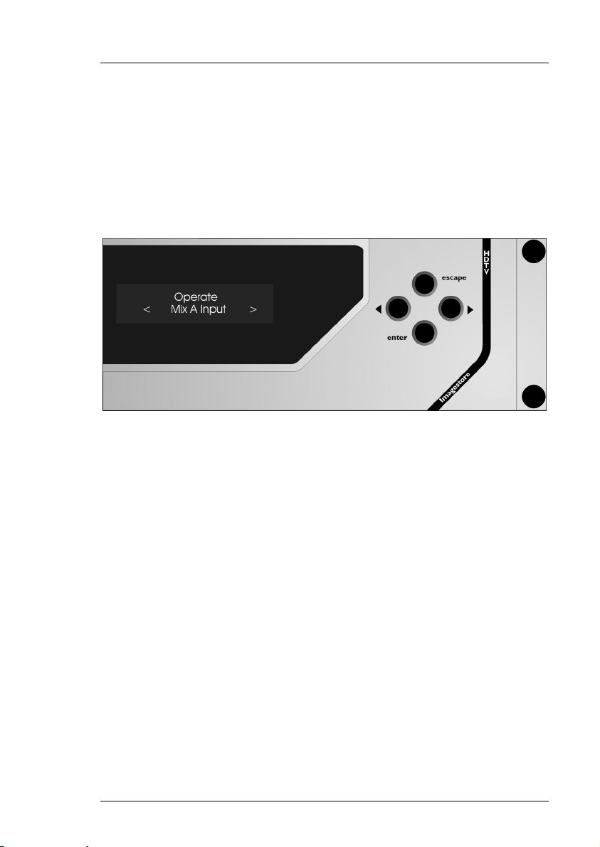
Symbols and Conventions
Front panel control of Imagestore HDTV is achieved using four keys in
conjunction with prompts from the display.
Where reference is made to a key the legend of the key will be shown in
lowercase italics (escape or enter) or by the icons W and X.
The two-line display provides a range of prompts in response to key presses.
Where reference is made to an actual display prompt this will be shown
italicised, e.g. Operate or Mix A Input.
Miranda Technologies Ltd Page 7
Page 8

Preface Imagestore HDTV User Manual
International Addresses
Canada Headquarters
Miranda Technologies Inc.
3499 Douglas-B.-Floreani
Montréal. QC
Canada H4S 2C6
Tel: +1 514 333 1772
Fax: +1 514 333 9828
Email amersales@miranda.com
Web www.miranda.com
USA Office
Miranda MTI
1101 North Pacific Ave, Suite 204
Glendale
CA, USA 91202
Tel: +1 818 550 8653
Fax: +1 818 550 8614
Email amersales@miranda.com
Web www.miranda.com
UK Office
Miranda Technologies Ltd.
Hithercroft Road, Wallingford,
Oxfordshire, OX10 9DG
UK
Tel: +44 (0) 1491 820000
Fax: +44 (0) 1491 820001
Email uksales@miranda.com
Web www.miranda.com
Asia Office
Miranda Asia KK
Mita Nexus Bldg. 2F
1-3-33 Mita, Minato-Ku
Tokyo, Japan 108-0073
Tel: +81-3-5730-2988
Fax +81-3-5730-2973
Support: +81-3-5730-2987
Email asiasales@miranda.com
Web www.miranda.com
Latin America Office
Miranda MTI
6175 N.W. 153
rd
St., Suite 300
Miami Lakes
FL, USA 33014-2443
Tel: +1 305 820 2990
Fax: +1 305 820 2991
Email jpunyed@miranda.com
Web www.miranda.com
European Sales Centre
Miranda Europe
222-226 rue de Rosny
93100 Montreuil
France
Tel: +33 (0) 1 55 86 87 88
Fax: +33 (0) 1 55 86 00 29
Email eurosales@miranda.com
Web www.miranda.com
Page 8 Miranda Technologies Ltd
Page 9

Imagestore HDTV User Manual Preface
Manual Structure
Overview
The overview provides an introduction to the Miranda Technologies Ltd
Imagestore HDTV for new users and describes the functions and features
offered by the product. It includes a simple technical concept of the unit and
details the optional modules that are available to enhance the unit's
capabilities.
Front Panel Operations
This section describes how to operate Imagestore HDTV using the frontpanel controls. Each manual function, feature and parameter is fully
described.
Installation
This section contains details of the unit interconnections and interfaces. It
describes all the set-up procedures required for a successful installation
including reference source selection, internal timing and synchronisation setup.
Support
The support section describes the procedures for using the return-to-base
warranty. It explains how to contact the Miranda Technologies Ltd technical
support team and outlines a series of preliminary unit checks that should be
made prior to calling.
Appendix 1 Product Specification
This appendix provides a summary of the specifications of Imagestore
HDTV.
Miranda Technologies Ltd Page 9
Page 10

Preface Imagestore HDTV User Manual
Appendix 2 Glossary
This appendix contains a guide to the terms and abbreviations found within
this user guide.
Appendix 3 Menu Tree
This appendix contains a series of diagrams representing the front panel
operation and configuration menu trees.
Appendix 4 Custom Configuration Notes
This appendix provides blank pages that may be used to record useful unit
configuration data.
Page 10 Miranda Technologies Ltd
Page 11

Imagestore User Manual Table of Contents
Table of Contents
Preface 3
Warranty--------------------------------------------------------------------------- 3
Important Safety Notices ------------------------------------------------------ 4
Injury Precautions ------------------------------------------------------------- 4
Product Damage Precautions---------------------------------------------- 5
Certifications and Compliances-------------------------------------------- 5
Scope of the Manual------------------------------------------------------------ 6
Associated Publications ----------------------------------------------------- 6
Symbols and Conventions ---------------------------------------------------- 7
International Addresses-------------------------------------------------------- 8
Manual Structure ---------------------------------------------------------------- 9
Overview ------------------------------------------------------------------------ 9
Front Panel Operations ------------------------------------------------------ 9
Installation----------------------------------------------------------------------- 9
Support -------------------------------------------------------------------------- 9
Appendix 1 Product Specification ----------------------------------------- 9
Appendix 2 Glossary --------------------------------------------------------10
Appendix 3 Menu Tree------------------------------------------------------ 10
Appendix 4 Custom Configuration Notes-------------------------------10
Table of Contents 11
Overview 19
Introduction ----------------------------------------------------------------------19
Applications---------------------------------------------------------------------- 19
Concept---------------------------------------------------------------------------19
Miranda Technologies Ltd Page 11
Page 12

Table of Contents Imagestore HDTV User Manual
Block Diagram ---------------------------------------------------------------- 20
Video Standards---------------------------------------------------------------- 21
Getting Started------------------------------------------------------------------ 21
Applying Power--------------------------------------------------------------- 21
Boot-Up Sequence ---------------------------------------------------------- 22
Facilities and Features-------------------------------------------------------- 22
Image Loading and Distribution ------------------------------------------ 22
Image Editing ----------------------------------------------------------------- 23
Transmission------------------------------------------------------------------ 23
Animated Images ------------------------------------------------------------ 23
AB Mixer ----------------------------------------------------------------------- 24
Timing, Control and Automation------------------------------------------ 24
Mechanical Bypass---------------------------------------------------------- 25
Options ------------------------------------------------------------------------- 25
Checking Installed Options --------------------------------------------- 25
Front Panel Display -------------------------------------------------- 26
Emergency Alert System--------------------------------------------------- 26
Front Panel Operations 27
Controls ------------------------------------------------------------------------ 27
VFD Display ------------------------------------------------------------------- 27
Escape and Enter Keys ---------------------------------------------------- 28
Left and Right Arrow Keys (W X) ---------------------------------------- 28
Opening screen--------------------------------------------------------------- 28
Operate --------------------------------------------------------------------------- 29
Set Inputs ---------------------------------------------------------------------- 29
Set Inputs menu tree ----------------------------------------------------- 29
Standard Colours --------------------------------------------------------- 30
Mix A Input--------------------------------------------------------------------- 31
Mix A Input menu tree---------------------------------------------------- 31
Mix B Input--------------------------------------------------------------------- 33
Mix B Input menu tree---------------------------------------------------- 33
AB Mixer ----------------------------------------------------------------------- 35
AB Mixer menu tree ------------------------------------------------------ 35
Cut To A --------------------------------------------------------------------- 37
Cut To B --------------------------------------------------------------------- 37
Page 12 Miranda Technologies Ltd
Page 13

Imagestore HDTV User Manual Table of Contents
Cut AB------------------------------------------------------------------------37
Fade To A ------------------------------------------------------------------- 37
Fade To B ------------------------------------------------------------------- 37
Fade AB ---------------------------------------------------------------------37
Transition Type.------------------------------------------------------------37
Mix Rate. --------------------------------------------------------------------37
V-Fade-Colour.-------------------------------------------------------------38
Standard Colours -----------------------------------------------------38
Layer 0 (DSK 1, Midground)----------------------------------------------- 39
Keyer Operations-------------------------------------------------------------40
Keyer Operations menu tree--------------------------------------------41
Cut Keyer Up --------------------------------------------------------------- 42
Cut Keyer Down -----------------------------------------------------------42
Set Key Parameters ------------------------------------------------------42
Source------------------------------------------------------------------- 42
Type----------------------------------------------------------------------42
Sense-------------------------------------------------------------------- 42
Clip, Gain & Trans---------------------------------------------------------43
Clip ----------------------------------------------------------------------- 43
Gain ---------------------------------------------------------------------- 43
Transparency ---------------------------------------------------------- 43
Fade Keyer Up ------------------------------------------------------------- 43
Fade Keyer Down --------------------------------------------------------- 43
Fade Rate ------------------------------------------------------------------- 44
Cut From Black ------------------------------------------------------------44
Cut To Black ---------------------------------------------------------------- 44
Fade From Black ----------------------------------------------------------44
Fade To Black--------------------------------------------------------------44
FTB Rate --------------------------------------------------------------------44
Input Operations--------------------------------------------------------------45
Input Operations menu tree--------------------------------------------- 45
Load Input------------------------------------------------------------------- 45
Unload Input ----------------------------------------------------------------45
Store Operations -------------------------------------------------------------46
Store Operations menu tree --------------------------------------------46
Load Image -----------------------------------------------------------------47
Set Position ----------------------------------------------------------------- 47
Horizontal--------------------------------------------------------------- 47
Vertical ------------------------------------------------------------------47
Miranda Technologies Ltd Page 13
Page 14

Table of Contents Imagestore HDTV User Manual
Set Masking ---------------------------------------------------------------- 47
Disable ------------------------------------------------------------------ 47
Setup -------------------------------------------------------------------- 47
Save Image----------------------------------------------------------------- 48
Unload Image -------------------------------------------------------------- 48
Image Load Mode--------------------------------------------------------- 48
Clean Load------------------------------------------------------------- 48
Cut Load---------------------------------------------------------------- 48
Layer 1 (DSK 2, Foreground) --------------------------------------------- 48
Preview Select---------------------------------------------------------------- 49
Preview Select menu tree----------------------------------------------- 49
Miscellaneous----------------------------------------------------------------- 51
Miscellaneous menu tree------------------------------------------------ 51
Delay ------------------------------------------------------------------------- 51
Emergency To Air--------------------------------------------------------- 52
Emergency From Air ----------------------------------------------------- 52
Set-Up ---------------------------------------------------------------------------- 53
GPI Inputs --------------------------------------------------------------------- 53
GPI Inputs menu tree ---------------------------------------------------- 53
Input to GPI----------------------------------------------------------------- 54
Create a Macro ------------------------------------------------------------ 54
Set ---------------------------------------------------------------------------- 55
Show ------------------------------------------------------------------------- 59
Clear-------------------------------------------------------------------------- 59
GPI Outputs ------------------------------------------------------------------- 60
GPI Outputs menu tree -------------------------------------------------- 60
Output from GPI ----------------------------------------------------------- 61
Create an output ---------------------------------------------------------- 61
Set ---------------------------------------------------------------------------- 61
Show ------------------------------------------------------------------------- 62
Clear-------------------------------------------------------------------------- 62
Faders Set Up ---------------------------------------------------------------- 63
Faders Set-Up menu tree ----------------------------------------------- 63
Configuration --------------------------------------------------------------- 64
Fader------------------------------------------------------------------------- 65
ADC Channels -------------------------------------------------------- 65
Enable Control ------------------------------------------------------------- 65
Invert Control--------------------------------------------------------------- 65
Page 14 Miranda Technologies Ltd
Page 15

Imagestore HDTV User Manual Table of Contents
Enable Pickup -------------------------------------------------------------- 65
File Operations----------------------------------------------------------------66
File Operations menu tree-----------------------------------------------66
Copy Image From FD ----------------------------------------------------67
Erase Image ---------------------------------------------------------------- 67
Configuration Save--------------------------------------------------------67
Configuration Load-------------------------------------------------------- 67
Diagnostic Save -----------------------------------------------------------67
System Information ----------------------------------------------------------68
System Information menu tree ----------------------------------------- 68
Serial Number -------------------------------------------------------------- 69
Slot 1-6----------------------------------------------------------------------- 69
Operating System --------------------------------------------------------- 69
IP Address ------------------------------------------------------------------69
Network Mask --------------------------------------------------------------69
Current Time----------------------------------------------------------------69
Running Since--------------------------------------------------------------69
View Licences----------------------------------------------------------------- 70
Set Time of Day -------------------------------------------------------------- 70
Set Time-of-Day menu tree ---------------------------------------------71
Year--------------------------------------------------------------------------- 71
Month------------------------------------------------------------------------- 71
Day---------------------------------------------------------------------------- 71
Hour -------------------------------------------------------------------------- 71
Min ----------------------------------------------------------------------------71
Min ----------------------------------------------------------------------------71
Self Tests-----------------------------------------------------------------------72
Self Tests menu tree -----------------------------------------------------72
Severity 1-------------------------------------------------------------------- 72
Severity 2-------------------------------------------------------------------- 72
Severity 3-------------------------------------------------------------------- 72
System Set-Up----------------------------------------------------------------73
System-Set-Up menu tree-----------------------------------------------73
Set Standard----------------------------------------------------------------75
Serial Comms Setup------------------------------------------------------ 75
Timecode Option ----------------------------------------------------------75
IP Address ------------------------------------------------------------------75
Network Mask --------------------------------------------------------------76
Restart System-------------------------------------------------------------76
Miranda Technologies Ltd Page 15
Page 16

Table of Contents Imagestore HDTV User Manual
Clean Restart -------------------------------------------------------------- 76
Update Software ---------------------------------------------------------- 76
Installation 77
Ventilation------------------------------------------------------------------------ 77
Power Requirements---------------------------------------------------------- 77
Environment --------------------------------------------------------------------- 77
Cabling---------------------------------------------------------------------------- 77
HDTV Rear Panel Connections -------------------------------------------- 78
PCI Connectors -------------------------------------------------------------- 78
RS422(A/B)----------------------------------------------------------------- 78
Oxtel RCP------------------------------------------------------------------- 79
RS232------------------------------------------------------------------------ 79
GPI---------------------------------------------------------------------------- 80
VGA and KBD Connections -------------------------------------------- 81
VGA---------------------------------------------------------------------- 81
KBD---------------------------------------------------------------------- 82
LAN--------------------------------------------------------------------------- 82
REF 1 / 2 -------------------------------------------------------------------- 83
Connection of LTC----------------------------------------------------------- 83
Mains Input ----------------------------------------------------------------- 83
HD-SDI source inputs---------------------------------------------------- 84
Input options----------------------------------------------------------- 84
Video Relay Bypass ------------------------------------------------------ 85
Connection of Analogue Faders------------------------------------------ 85
Connection of General Purpose Interfaces (GPIs) ------------------ 86
Input to GPI----------------------------------------------------------------- 86
Output from GPI ----------------------------------------------------------- 86
Support 87
Product Support ---------------------------------------------------------------- 87
Warranty and Non-Warranty Repairs ----------------------------------- 87
Obsolescence----------------------------------------------------------------- 88
Upgrades----------------------------------------------------------------------- 88
Page 16 Miranda Technologies Ltd
Page 17

Imagestore HDTV User Manual Table of Contents
Service Visits ------------------------------------------------------------------ 88
Equipment Loans-------------------------------------------------------------88
Training -------------------------------------------------------------------------88
Web Page---------------------------------------------------------------------- 89
Returns Procedure ------------------------------------------------------------- 89
Transit Packaging ------------------------------------------------------------ 89
Appendix 1 91
Imagestore specifications ----------------------------------------------------91
HD-SDI Inputs and Outputs------------------------------------------------91
Reference Video Input ------------------------------------------------------91
Power Requirements -------------------------------------------------------- 91
Interfaces----------------------------------------------------------------------- 91
Mechanical--------------------------------------------------------------------- 92
Environmental----------------------------------------------------------------- 92
Appendix 2 93
Glossary --------------------------------------------------------------------------93
Appendix 3 95
Menu Tree------------------------------------------------------------------------95
Appendix 4 101
Custom Configuration Notes----------------------------------------------- 101
Miranda Technologies Ltd Page 17
Page 18

Table of Contents Imagestore HDTV User Manual
Page 18 Miranda Technologies Ltd
Page 19

Imagestore HDTV User Manual Overview
Overview
Introduction
This introduction provides a basic overview of the concept of the unit and
includes instructions for getting started.
An extensive range of options and upgrades are available for Imagestore
HDTV and this section describes the purpose and features of each
enhancement. More detailed and specific information regarding operation,
configuration, installation and support are provided in later sections.
Imagestore HDTV (Product code IS-HDTV) is part of Miranda Technologies
Ltd's professional broadcast equipment range of products and its primary use
is to insert logos into a HD-SDI digital video signal. The capabilities of this
2U unit include simple logo insertion, still and animated images.
Applications
Imagestore HDTV is typically used to insert a still or animated logo, a
channel identification, a programme schedule, an advertisement, an
emergency image, or a combination of any two of those. Each of these
resources may be brought on-air from the 40-image library (optionally 400 or
1000 image). Alternatively, external 'live' fill and key signals from a
character generator, or a still/animation store, can be directly inserted into the
HD signal.
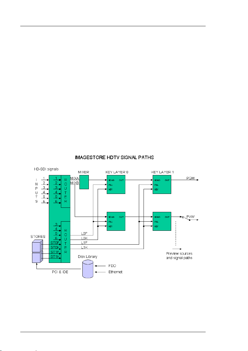
Concept
Imagestore HDTV is set up for operation where the two keyers are arranged
in series as shown below. This configuration allows two images to be keyed
simultaneously, but independently, over the background video.
A fail-safe mechanical Video Relay Bypass option (VRB-HD-001) is
available that directly connects the background video source to the
programme output in the event of a power supply problem.
Miranda Technologies Ltd Page 19
Page 20
Overview Imagestore HDTV User Manual
Still (.oxt) and animated (.oxa) images are typically stored in the unit's hard
disk library. Images may be added to the library using the floppy disk drive
but the files must be in an appropriate format. Miranda Technologies Ltd's
Media Conversion Software (MCS-002-HD) is designed for this purpose and
is supplied with each Imagestore HDTV.
An Ethernet interface option (NET-HD-001) provides for the rapid loading of
images and animations over either a co-axial or twisted pair network using
MCS. This interface also enables the transference of images between a PC
workstation and Imagestore using Miranda Technologies Ltd's Media
Distribution System (MDS). The MDS software provides for transfer and
management of still-images and animations. Files may also be transferred
using an FTP program.
Block Diagram
Page 20 Miranda Technologies Ltd
Page 21
Imagestore HDTV User Manual Overview
Video Standards
Imagestore HDTV v1.02, supports SMPTE 292M 1.485Gb/s at the following
resolutions:
1920 x 1080i/59.94 Hz SMPTE 274M 1998
1920 x 1080i/50 Hz SMPTE 274M 1998
1280 x 720/59.94 Hz SMPTE 296M 2001
Standard Words
SMPTE
274M
1920 x
1080/
59.94/2:1
1920 x
1080/
50/2:1
SMPTE
296M
1280 x
720/ 59.94
per
active
line
(S/AL)
1920 1080 30/1.001 2:1
1920 1080 25 2:1
1280 720 60/1.001 1:1
Active
lines
per
frame
Frame
rate
(Hz)
Scanning
format
interlace
interlace
Progressive
Interface
sampling
frequency
(MHz)
F
s
74.25/1.001 2200 1125
74.25 2640 1125
74.25/1.001 1650 750
Words
per
total
line
(S/TL)
Total
lines
per
frame
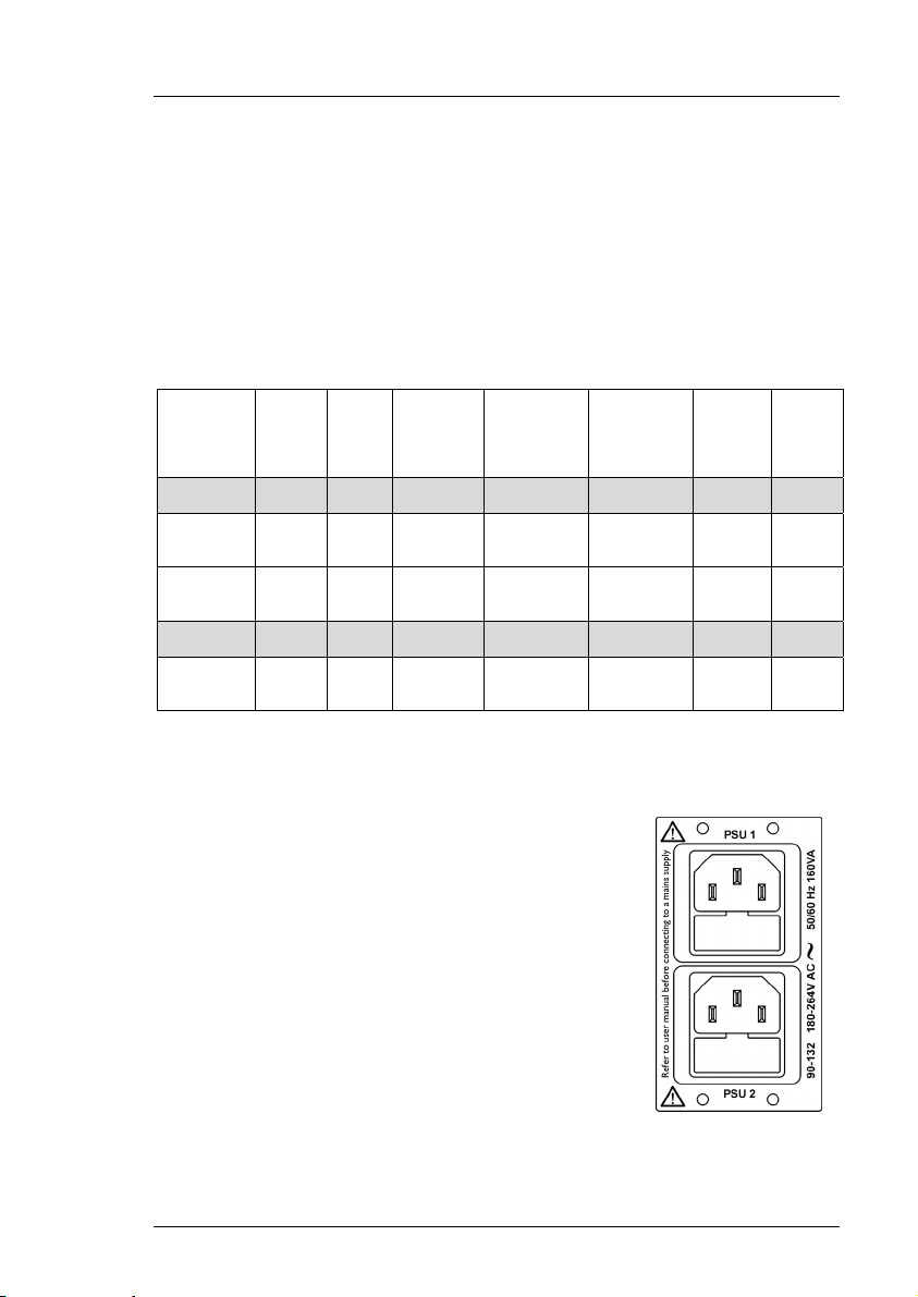
Getting Started
Applying Power
Before applying power, ensure that the floppy disk
drive does not contain a disk.
Imagestore HDTV does not have a power on/off
switch and power is applied immediately when the
IEC plug is connected to mains power. The product
should be connected to the mains via an appropriate
circuit breaker. In the event the second PSU option
(PSU-HD-001) in not fitted always connect to the IEC
socket labelled PSU1 first.
Miranda Technologies Ltd Page 21
Page 22

Overview Imagestore HDTV User Manual
Boot-Up Sequence
Once power is applied Imagestore HDTV will boot automatically and the
complete process takes about 30 seconds. The unit first checks to see if there
is a disk in the floppy drive and, if it finds one, it will attempt to boot from
that disk. Miranda Technologies Ltd issues specialised floppy disks for use as
part of the boot-up sequence when software upgrades are being implemented.
No other disk should ever be present in the floppy disk drive during the boot
sequence. The boot sequence is complete when the following top level "bootup" menu appears on the front panel VFD display.
Facilities and Features
Image Loading and Distribution
The entry-level Imagestore HDTV provides storage for up to forty full-screen
images with their associated keys and this can currently be upgraded to 400
or 1000 images. Each animated clip is counted as one single image stored in
the library. With large or long duration animations (where the total pixel
count of the animation exceeds one full-screen frame) the total number of full
screen frames used counts towards the permitted maximum of full-screen
images in the library.
Images (.oxt) and animation (.oxa) files saved to floppy disks from Miranda
Technologies Ltd's Media Conversion Software - (or other Miranda
Technologies Ltd units) can be loaded in the same way. The Media
Page 22 Miranda Technologies Ltd
Page 23

Imagestore HDTV User Manual Overview
Conversion software allows large animations and images to be saved across
multiple floppy disks (span files .oxm), using loss-less compression to reduce
the number of disks required.
Miranda Technologies Ltd also provides an image transfer and management
system for Imagestore HDTV. The Media Distribution System (MDS) uses a
local area network to connect the workstation to a number of Miranda
Technologies Ltd's image and audio insertion products. Details of MDS are
contained in a separate manual user guide.
Image Editing
The image editor permits an operator to position an image/animation (both
horizontally and vertically), mask the image/animation and adjust the clip,
gain and transparency levels prior to transmission.
Transmission
Once prepared, an image/animation can be saved in the image library and
sent to air using fade and cut transitions.
Animated Images
Imagestore HDTV provides image animation, for applications such as
moving logos, messages and emergency images. The image motion system
provides storage and live playout for up to 40, (optionally 400 or 1000) full,
or part-screen images of variable duration.
The maximum animation length is dependent upon both the screen-size of the
images and the playout memory installed in the Imagestore HDTV.
There are two video stores, which may be used to hold text, stills or moving
logos. The images may be any size up to full screen. Stored images and their
associated keys are stored and processed at 10 bit resolution. (Unless the
image is stored without key to save space in which case it is stored at 8 bit
resolution.)
The time for larger animations, up to full screen, are reduced proportionally
to the area used. Areas are evaluated each frame so bugs may change in size
with no penalty.
Miranda Technologies Ltd Page 23
Page 24
Overview Imagestore HDTV User Manual
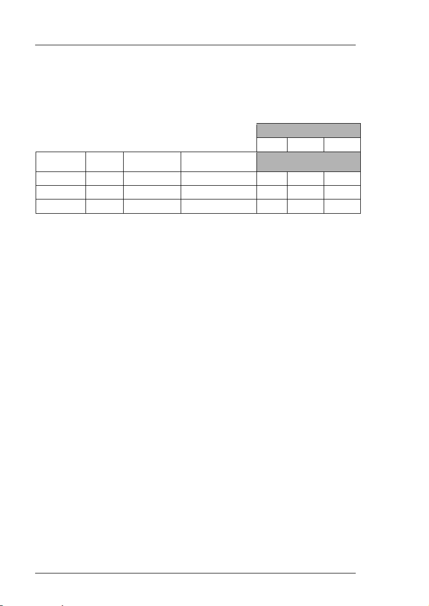
With 256MB of playout memory, a logo of ¹/64 screen size can be animated
for just over a minute. Larger screen sizes or smaller playout memory sizes
affect the maximum animation time pro rata.
HDTV
Standard
1080i 59.94 29.97 7.91 8.0 16.1 32.2
Duration (s) 1/16th frame > 4.3s 8.6s 17.2s
1/64th frame > 17.0s 34.3s 68.8s
Rate Frame rate MB per frame
Memory option
64 128 256
Max no. of frames
Moving images are constructed from component images using the animation
builder software provided as part of the Media Conversion Software package
supplied with Imagestore HDTV.
Component images are imported into the animation builder utility from 32-bit
Targa image files thus allowing components to originate from almost any
computer graphics system.
AB Mixer
The optional integral AB Mixer (MIX-HD-001) video switcher is designed to
be fed by an any of the units input sources or by an external router under
automation control. The mixer provides cut and cross fade transitions with
variable fade rates.
Timing, Control and Automation
Imagestore is designed to be easy to install. One line FIFO's are provided on
each input for simplified system timing.
Other valuable set-up and control features include a menu-driven front panel
VFD display, a General Purpose Interface (GPI) macro editor and a facility to
load configuration settings from, and save system configurations to, a floppy
disk.
Page 24 Miranda Technologies Ltd
Page 25

Imagestore HDTV User Manual Overview
Imagestore HDTV is highly suited to automated broadcast environments and
remote control options include RS422/RS232, as well as GPI and analogue
fader inputs.
Mechanical Bypass
In the event of power loss to the Imagestore HDTV, or failure of an internal
power supply, the mechanical video relay bypass option (VRB-HD-001)
routes the serial digital "background signal" directly to the programme
output. This feature is an emergency failsafe and is completely nonsynchronous in operation. During boot-up, the bypass is maintained until
Imagestore HDTV is fully operational.
Options
Status information regarding the options included with each Imagestore
HDTV can be accessed from the front panel display, using the panel control
keys as described later in this guide.
The following table lists the options with their identifying codes and briefly
describes the purpose.
Option Description
MEM-HD-400V Image Library expansion to 400 frames with 2 x 128MB playout memory.
MEM-HD-1000V Image Library expansion to 1000 frames with 2 x 256MB playout memory.
MIX-HD-001 A/B video mixer
IP2-HD-001 2 video input option. Replaces standard single input board.
IP4-HD-001 4 video input option. Only used in conjunction with IP2-HD-001.
IP6-HD-001 6 video input option. Only used in conjunction with IP2-HD-001 and IP4-HD-001.
VRB-HD-001 Mechanical Video Relay Bypass
PSU-HD-001 Dual power supply option
NET-HD-001 10/100MB Ethernet interface RJ45
MDS-002-HD Media Distribution System (requires NET-002 Option).
EAS-HD-001 Emergency Alert System support
Checking Installed Options
The Imagestore HDTV can display the internal options installed from the
front panel display.
Miranda Technologies Ltd Page 25
Page 26

Overview Imagestore HDTV User Manual
Front Panel Display
From the opening screen press the right arrow key X to display Set-Up then
press the enter key to display the Set-Up menu.
Press the right arrow key Xuntil View Licenses appears on the second line of
the display then press the enter key. Repeatedly pressing the X key will now
cycle the display through a list of the fitted options. When completed, press
the escape key a few times until the boot-up menu reappears.
License Code Option
ABMX:0 A/B video mixer
ENET:0 10/100 Ethernet Interface
ILIB:400 400 Image library
ILIB:1000 1000 Image library
EAS1:0 Emergency Alert Service
Emergency Alert System
Imagestore HDTV supports EAS providing the relevant license is installed.
The 2 EAS models supported are:
♦ Sage ENDEC Model 1822
♦ TFT EAS 911T
To configure a communication port to accept the EAS data stream refer to the
Serial Comms Setup section on page 69.
Page 26 Miranda Technologies Ltd
Page 27

Imagestore HDTV User Manual Front Panel Operation
Front Panel Operations
This section of the manual explains, on a task-by-task basis, the operation of
an Imagestore HDTV using only the front panel controls. Each task is fully
detailed, making reference to other sections unnecessary.
Controls
All of Imagestore HDTV's operational and configuration features can be
monitored and controlled from the front panel of the unit using the
pushbuttons and display. A simple menu-driven procedure provides access to
the operational, configuration and set-up options.
The front panel of Imagestore HDTV contains a 3½ floppy disk drive, four
push-button control keys and a vacuum fluorescent display (VFD). Local
control of the unit is "menu driven" using a combination of the push-button
keys together with options displayed on the VFD. The upper key of the group
is identified on the panel as the escape key and the bottom key is identified as
the enter key. Left and right keys W X are used to move a cursor left and
right accordingly to select menu options.
VFD Display
The alphanumeric VFD display is divided into two separate lines. The upper
row of characters indicating the function and the lower row indicating the
current selection and any optional configuration changes that are available.
Where there are more options available than there is room for on the display,
the symbols W and X are used to indicate that other options exist to the left
and right respectively. Using the appropriate arrow key will reveal those
options.
Any options shown in brackets i.e. (AB Mixer) denotes a licensed option
where the appropriate license has not been installed.
Miranda Technologies Ltd Page 27
Page 28

Front Panel Operation Imagestore HDTV User Manual
Escape and Enter Keys
The escape key is used to proceed to a menu option closer to the boot-up
menu. Successive pressing of the key will bring the display to the start-up
menu. The enter key is used to accept the menu item currently shown as
selected by being enclosed in brackets.
Left and Right Arrow Keys (W X)
Left and right arrow keys W X may be used to index left and right
respectively along a displayed menu branch to select a function. When a
selection of parameters is offered, these keys may be used to select a
variable. Where a single value is displayed the left arrow key may be used to
reduce the displayed value and the right key may be used to increase it.
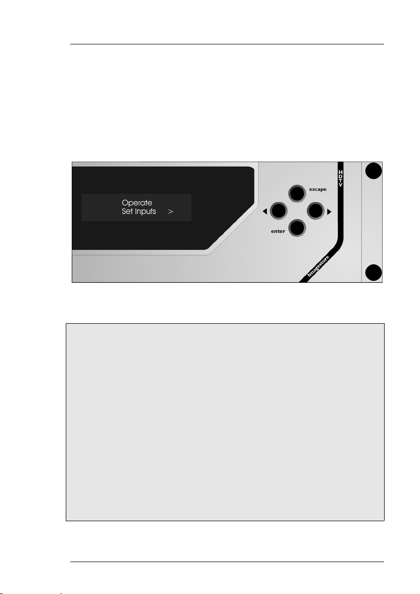
Opening screen
The Imagestore HDTV menu has two branches:
Operate Set-up
From the opening screen with Operate displayed press the enter key.
Page 28 Miranda Technologies Ltd
Page 29
Imagestore HDTV User Manual Front Panel Operation
Operate
Set Inputs
Select Operate, Set Inputs.
Set Inputs menu tree
Operate
Set Inputs
1/A
Force Colour Field RGB 0 <> 100%
Pass SDI
2/B
Force Colour Field RGB 0 <> 100%
Pass SDI
3/Fill-1
Force Colour Field RGB 0 <> 100%
Pass SDI
4/Key-1
Force Colour Field RGB 0 <> 100%
Pass SDI
5/Fill-2
Force Colour Field RGB 0 <> 100%
Pass SDI
Miranda Technologies Ltd Page 29
Page 30

Front Panel Operation Imagestore HDTV User Manual
6/Key-2
Force Colour Field RGB 0 <> 100%
Pass SDI
The factory default setting for each input is to Pass-SDI. If the input is
unused/unconnected it can be set to internally generate a colour field.
Using the front panel control keys (W X enter) select the input you wish to
modify. To adjust the colour field select Force Colour Field then press the
enter key.
The colour field is set by adjusting the RGB (Red, Green, Blue) values, from
0% to 100%, for each colour in turn. Using the arrow keys W X, increase or
decrease the field value then, when the desired value is reached press the
enter key. After adjusting the Red value the Green field will be displayed
then the Blue. Pressing the enter key after adjusting the Blue value will
accept the change. To go back a level press escape key.
Standard Colours
Colour Red (%) Green (%) Blue (%)
White 100 100 100
Yellow 100 100 0
Cyan 0 100 100
Green 0 100 0
Magenta 100 0 100
Red 100 0 0
Blue 0 0 100
Black 0 0 0
Page 30 Miranda Technologies Ltd
Page 31

Imagestore HDTV User Manual Front Panel Operation
Mix A Input
Select Operate, Mix A Input.
Mix A Input menu tree
Operate
Mix A Input
1/A
2/B
3/Fill-1
4/Key-1
5/Fill-2
6/Key-2
Miranda Technologies Ltd Page 31
Page 32

Front Panel Operation Imagestore HDTV User Manual
This option is used to select the SDI source that will become the Mix A Input
for the A/B Video mixer.
A maximum of 3 inputs cards may be fitted to the Imagestore HDTV
allowing selection from up to 6 inputs. The illustration below shows the
maximum configuration.
Using the front panel control keys (W X) display the input source you wish
to select then press the enter key.
To go back a level press escape key.
Page 32 Miranda Technologies Ltd
Page 33

Imagestore HDTV User Manual Front Panel Operation
Mix B Input
Select Operate, Mix B Input.
Mix B Input menu tree
Operate
Mix B Input
1/A
2/B
3/Fill-1
4/Key-1
5/Fill-2
6/Key-2
Miranda Technologies Ltd Page 33
Page 34

Front Panel Operation Imagestore HDTV User Manual
This option is used to select the SDI source that will become the Mix B Input
for the A/B Video mixer.
Using the front panel control keys (W X) display the input source you wish
to select then press the enter key.
To go back a level press escape key.
Note This menu is only available if the AB Mixer option is installed.
Page 34 Miranda Technologies Ltd
Page 35

Imagestore HDTV User Manual Front Panel Operation
AB Mixer
Select Operate, AB Mixer.
AB Mixer menu tree
Operate
AB Mixer
Cut To A
Cut To B
Cut AB
Fade To A
Fade To B
Fade AB
Transition Type
V Fade
X Fade
Cut
Mix Rate
Fields 1 - 300
V-Fade-Colour
Red 0 <> 100%
Green 0 <> 100%
Blue 0 <> 100%
Miranda Technologies Ltd Page 35
Page 36

Front Panel Operation Imagestore HDTV User Manual
The AB mixer is an integral 2 input video switcher, which provides the
background video source to the program keyers. The mixer can be configured
for both cut and variable fade transitions from this menu. Using the front
panel control keys (W X) display the transition type you wish to select then
press the enter key.
Note pressing the enter key will activate the transition.
A CUT transition is an instant switch to the selected source. This is achieved
between frames in the vertical interval so the active picture is allowed to
finish before the new data is transmitted.
A FADE transition is the gradual process of switching to the selected source
with rates adjustable between 1 and 300 fields (5 seconds @ 60Hz)
Page 36 Miranda Technologies Ltd
Page 37

Imagestore HDTV User Manual Front Panel Operation
The options are:
Cut To A
Selects the Mix A Input as the background video source.
Cut To B
Selects the Mix B Input as the background video source.
Cut AB
Switches between the Mix A input and the Mix B input.
Fade To A
Fades in the Mix A Input as the background video source. The rate, in fields,
is set by the Mix Rate command.
Fade To B
Fades in the Mix B Input as the background video source. The rate, in fields,
is set by the Mix Rate command.
Fade AB
Fades between the Mix A input and the Mix B input. The rate, in fields, is set
by the Mix Rate command.
Transition Type.
Use this option to select the transition type, V Fade, X Fade or Cut.
Mix Rate.
Use this option to select the number of fields to action a Fade. Using the
arrow control keys W X adjust the value between 1 – 300 fields. Press the
enter key to accept the value.
Note At 1080i/59.94 60 fields = 1 second.
Miranda Technologies Ltd Page 37
Page 38

Front Panel Operation Imagestore HDTV User Manual
V-Fade-Colour.
This option allows the user to change the V fade colour from the default
factory setting of black to any colour of their choice by adjusting the RGB
values.
The colour is set by adjusting the RGB (Red, Green, Blue) values from 0% to
100% for each colour in turn. Using the arrow keys W X, increase or
decrease the field then when the desired value is reached press the enter key.
After adjusting the Red value the Green field will be displayed then the Blue.
Pressing the enter key after adjusting the Blue value will accept the change.
To go back a level press escape key.
Standard Colours
Colour Red (%) Green (%) Blue (%)
White 100 100 100
Yellow 100 100 0
Cyan 0 100 100
Green 0 100 0
Magenta 100 0 100
Red 100 0 0
Blue 0 0 100
Black 0 0 0
Page 38 Miranda Technologies Ltd
Page 39

Imagestore HDTV User Manual Front Panel Operation
Layer 0 (DSK 1, Midground)
Imagestore HDTV has 2 keying layers per channel (program and preview).
The output from the AB Mixer forms the background video image on the
program keyer, which can also accept a Fill and Key signal from either,
inputs 3-6 or from the stores, as shown in the diagram below.
The following section describes how to control Key Layer 0
Miranda Technologies Ltd Page 39
Page 40

Front Panel Operation Imagestore HDTV User Manual
Select Operate, Layer 0.
Layer 0 menus are split into 3 sub-headings:
♦ Keyer Operations
♦ Input Operations
♦ Store Operations
Keyer Operations
Select Operate, Layer 0, Keyer Operations.
Page 40 Miranda Technologies Ltd
Page 41

Imagestore HDTV User Manual Front Panel Operation
Keyer Operations menu tree
Operate
Layer 0
Keyer Operations
Cut Keyer Up
Cut Keyer Down
Set Key Parameters
Source
Self
Separate
None
Type
Full
Linear
Sense
Normal
Invert
Clip, Gain & Trans
Clip (Value 0 to 1023)
Gain (Value 0 to 1023)
Trans (Value 0 to 512)
Fade Keyer Up
Fade Keyer Down
Fade Rate
(Value in fields 1 to 300)
Cut From Black
Cut To Black
Fade From Black
Fade To Black
FTB Rate
(Value in fields 1 to 300)
A CUT transition is an instant switch to the selected source. This is achieved
between frames in the vertical interval so the active picture is allowed to
finish before the new data is transmitted.
Miranda Technologies Ltd Page 41
Page 42

Front Panel Operation Imagestore HDTV User Manual
A FADE transition is the gradual process of switching to the selected source
with rates adjustable between 1 and 300 fields (5 seconds @ 60Hz)
Cut Keyer Up
Displays the fill/key input source of Key Layer 0 over the background video.
Cut Keyer Down
Removes the fill/key input source of Key Layer 0 from being displayed over
the background video. The background video is passed unchanged.
Set Key Parameters
Source
Self key When the source option is set to self, the key data is derived from
the luminance content (Y value) of the "Fill" signal itself.
Separate key When the source option is set to separate, the key data is
derived from the luminance content (Y value) of the separate "Key" image.
None When the source option is set to none the key for an image is set to
white so that there is no image transparency.
Type
Full Key is where the foreground image is passed only where the key signal
is present.
Linear Key is where the background and foreground are summed and the
foreground is unaffected by the key.
Sense
Normal, a black-level key signal that will cause the "Fill" image to be fully
transparent and not appear over a background. A white-level key signal will
cause the "Fill" image to be opaque with no background appearing through.
Intermediate keying levels will produce a pro-rata transparency effect.
Invert reverses this effect and white-level key signals now create a fully
transparent "Fill" image with black-level signals producing an opaque "Fill"
image.
Page 42 Miranda Technologies Ltd
Page 43

Imagestore HDTV User Manual Front Panel Operation
Clip, Gain & Trans
These commands set the opacity levels for the fill/key source for Key Layer
0.
Clip
Clip is the level under which the key signal will be forced to black. In a
keying process this will result in a total absence of fill video in areas where
the incoming key signal is less than the clip level.
Gain
The gain level amplifies the key signal, forcing grey levels towards and up to
white. In a keying process this will result in the fill signal being less
transparent than it otherwise would be in areas with a grey key signal.
Transparency
Transparency controls the luminance content (grey scale value) of the key
signal and therefore the amount of background video that will 'seep' through
the keyed image.
Clip and Gain values are in the range of 0 (black) - 1023 (white),
Transparency is in the range of 0 (black) - 512 (white), and are adjusted using
the arrow control keys W X.
Fade Keyer Up
Gradually displays the key input source of Key Layer 0 over the background
video. The rate in fields is set by the Fade Rate command.
Fade Keyer Down
Gradually removes the displayed key input source of Key Layer 0 from the
background video. The rate, in fields, is set by the Fade Rate command.
Miranda Technologies Ltd Page 43
Page 44

Front Panel Operation Imagestore HDTV User Manual
Fade Rate
The Fade Rate is adjusted using the arrow control keys W X between 1 and
300 fields. Press the enter key to accept the value.
Note At 1080i/59.94 60 fields = 1 second.
Cut From Black
Switches the output from Key Layer 0 from black to background video plus
fill and key signals.
Cut To Black
Switches the output from Key Layer 0 from background video to black.
Fade From Black
Gradually changes the output from Key Layer 0 from black to background
video plus fill and key signals. The rate in fields is set by the FTB Rate
command.
Fade To Black
Gradually changes the output from Key Layer 0 to go black. The rate in
fields is set by the FTB Rate command.
FTB Rate
The Fade to Black rate is adjusted using the arrow control keys W X between
1 and 300 fields. Press the enter key to accept the value.
Note At 1080i/59.94 60 fields = 1 second.
Page 44 Miranda Technologies Ltd
Page 45

Imagestore HDTV User Manual Front Panel Operation
Input Operations
Select Operate, Layer 0, Input Operations.
Input Operations menu tree
Operate
Layer 0
Input Operations
Load Input
Fill-1/Key-1
Fill-2/Key-2
Unload Input
Load Input
Sets the fill/key input source for Key Layer 0. Select between Fill-1/Key-1 or
Fill-2/Key-2.
Note! The 4 or 6 video input options IP4 HD 001 / IP6 HD 001 must be
fitted.
Unload Input
Unloads the input.
Miranda Technologies Ltd Page 45
Page 46

Front Panel Operation Imagestore HDTV User Manual
Store Operations
Select Operate, Layer 0, Store Operations.
Store Operations menu tree
Operate
Layer 0
Store Operations
Load Image
Set Position
Horizontal (-1920 to 1920)
Vertical (-1080 to 1080)
Set Masking
Disable
Setup
Left
Right
Top
Bottom
Save Image
Unload Image
Image Load Mode
Clean-Load
Cut-Load
Page 46 Miranda Technologies Ltd
Page 47

Imagestore HDTV User Manual Front Panel Operation
Load Image
Selects a file from the image library to load into Store 0.
Still images (.oxt).
Animations (.oxa)
Set Position
Determines the on screen position of the image.
Horizontal
Use the arrow control keys W X to adjust the value between –1920 and 1920.
Position 0 is the top left hand corner of the screen.
Vertical
Use the arrow control keys W X to adjust the value between –1080 and 1080.
Position 0 is the top left hand corner of the screen.
Set Masking
Defines a mask area for the loaded image. The number range is determined
by the width and height of the image in pixels, –1. To maintain correct YUV
values the pixel count will increment in units of 2.
Disable
Ignores the Set Masking values.
Setup
Sets the Masking values.
Left
Use the arrow control keys W X to adjust the value. Press enter to accept or
escape to cancel.
Right
Use the arrow control keys W X to adjust the value. Press enter to accept or
escape to cancel.
Miranda Technologies Ltd Page 47
Page 48

Front Panel Operation Imagestore HDTV User Manual
Top
Use the arrow control keys W X to adjust the value. Press enter to accept or
escape to cancel.
Bottom
Use the arrow control keys W X to adjust the value. Press enter to accept or
escape to cancel.
Save Image
Saves an image to the image library including any masking values set.
Unload Image
Unloads the image from Store 0.
Image Load Mode
Defines how the image is loaded into Store 0.
Clean Load
Clean load removes the existing image from the store before loading the new
file. The image/animation will NOT be displayed until it is fully loaded.
Cut Load
Cut load is similar to Clean Load but the existing image remains active until
the new file is loaded. A cut transition then replaces the new image for the
old one.
Layer 1 (DSK 2, Foreground)
The commands for Layer 1 are identical to Layer 0.
Page 48 Miranda Technologies Ltd
Page 49

Imagestore HDTV User Manual Front Panel Operation
Preview Select
Select Operate, Preview Select.
Preview Select menu tree
Operate
Preview Select
Preview o/p
Program o/p
1/A
2/B
3/Fill-1
4/Key-1
5/Fill-2
6/Key-2
Store 0 Fill o/p
Store 1 Fill o/p
AB Mixer o/p
Layer 0 o/p
Store 0 Key o/p
Store 1 Key o/p
This option allows the user to switch the preview output from is dedicated
keyer output to any of the named signal paths.
Miranda Technologies Ltd Page 49
Page 50

Front Panel Operation Imagestore HDTV User Manual
Using the front panel control keys (W X) display the preview output source
you wish to monitor then press the enter key.
To go back a level press escape key.
Page 50 Miranda Technologies Ltd
Page 51

Imagestore HDTV User Manual Front Panel Operation
Miscellaneous
Select Operate, Miscellaneous.
Miscellaneous menu tree
Operate
Miscellaneous
Delay
Emergency To Air
Emergency From Air
These miscellaneous commands are used for setting the GPI macros delay (in
fields) and for and instigating the emergency to air facility in the event of
background video failure.
Delay
Use the front panel control keys (W X) to adjust the delay value, in fields.
When the delay function is called up within a GPI macro, the system will
pause for the specified number of fields.
Miranda Technologies Ltd Page 51
Page 52

Front Panel Operation Imagestore HDTV User Manual
Emergency To Air
In the event of a background video failure an emergency message can easily
be sent to air using this command. The emergency image must be stored in
the image library under filename V000.oxt.
When Emergency To Air is selected, Key Layer 1 on the program output
channel is faded down over 25 fields. Image V000.oxt is then loaded and
faded up over a further 25 fields.
Emergency From Air
When Emergency From Air is selected, Key Layer 1 on the program output
channel is faded down over 25 fields and the previous image is restored, but
not faded up.
Page 52 Miranda Technologies Ltd
Page 53

Imagestore HDTV User Manual Front Panel Operation
Set-Up
GPI Inputs
Select Set-Up, GPI Inputs.
GPI Inputs menu tree
Set-Up
GPI Inputs
GPI In 1 On
Set
Show
Clear
GPI In 1 Off
Set
Show
Clear
……………………………………..
GPI In 9 On
Set
Show
Clear
Miranda Technologies Ltd Page 53
Page 54

Front Panel Operation Imagestore HDTV User Manual
GPI In 9 Off
Set
Show
Clear
General Purpose Interface (GPI) ports may be used either to trigger the
execution of a series of Imagestore HDTV internal pre-programmed
commands (input) or to monitor the status of the Imagestore HDTV (output).
The nine GPI ports are identified as GPI 1 through GPI 9. The first seven
ports, GPI 1 through 7, may be configured as either input or output ports
whilst the remaining two, GPI 8 and GPI 9 may only be configured as inputs.
Any GPI, assigned to ‘input’, may have a macro associated with it that
contains up to 2K bytes of command data (approx. 200 commands strings).
When triggered, the commands within the macro execute sequentially. If the
GPI is assigned as an ‘output’, it may only have a single status associated
with it.
Input to GPI
Where a GPI port is used as an input, the command macro is activated when
either, the connection is made (GPI On) or switched off (GPI Off) relative to
the GPI ground pin (pin 13) on the GPI 25way D type connector.
To start a macro associated with GPI In 1 On, make connection between pins
25 (GPI0) and 13 (GPI GND)
To start a macro associated with GPI In 1 Off, break connection between pins
25 (GPI0) and 13 (GPI GND)
For connector information refer to the diagram on page 74.
Create a Macro
To create a macro, display the relevant GPI then press the enter key. The
next sub-menu offers three choices, Set, Show or Clear. To create a new
macro, select Set.
Page 54 Miranda Technologies Ltd
Page 55

Imagestore HDTV User Manual Front Panel Operation
Set
The Set menu offers the following range of Imagestore HDTV commands,
appropriate to the configured mode. Using the arrow keys W X display the
first command to be added to the macro and press enter to add it. The display
is now returned to the listing of the macro, showing the added command. To
add a second command, use the arrow keys W X to display the next
command and press the enter key as before. Further commands are added to
the macro using the same procedure. Approximately 200 command lines may
be added to the macro.
Set Inputs
1/A
Force Colour Field RGB 0 <> 100%
Pass SDI
2/B
Force Colour Field RGB 0 <> 100%
Pass SDI
3/Fill-1
Force Colour Field RGB 0 <> 100%
Pass SDI
4/Key-1
Force Colour Field RGB 0 <> 100%
Pass SDI
5/Fill-2
Force Colour Field RGB 0 <> 100%
Pass SDI
Mix A Input
1/A
2/B
3/Fill-1
4/Key-1
5/Fill-2
6/Key-2
Mix B Input
1/A
2/B
3/Fill-1
Miranda Technologies Ltd Page 55
Page 56

Front Panel Operation Imagestore HDTV User Manual
4/Key-1
5/Fill-2
6/Key-2
AB Mixer
Cut To A
Cut To B
Cut AB
Fade To A
Fade To B
Fade AB
Transition Type
V Fade
X Fade
Cut
Mix Rate
Fields 1 - 300
V Fade Colour
Red 0 <> 100%
Green 0 <> 100%
Blue 0 <> 100%
Layer 0
Keyer Operations
Cut Keyer Up
Cut Keyer Down
Set Key Parameters
Source
Self
Separate
None
Type
Full
Linear
Sense
Normal
Invert
Clip, Gain & Trans
Clip (Value 0 to 1023)
Gain (Value 0 to 1023)
Trans (Value 0 to 512)
Page 56 Miranda Technologies Ltd
Page 57

Imagestore HDTV User Manual Front Panel Operation
Fade Keyer Up
Fade Keyer Down
Fade Rate
(Value in fields 1 to 300)
Cut From Black
Cut To Black
Fade From Black
Fade To Black
FTB Rate
(Value in fields 1 to 300)
Input Operations
Load Input
Fill-1/Key-1
Fill-2/Key-2
Unload Input
Store Operations
Load Image
Set Position
Horizontal (-1920 to 1920)
Vertical (-1080 to 1080)
Set Masking
Disable Masking
Setup
Left
Right
Top
Bottom
Save Image
Unload Image
Image Load Mode
Clean-Load
Cut-Load
Layer 1
Keyer Operations
Cut Keyer Up
Cut Keyer Down
Set Key Parameters
Source
Self
Miranda Technologies Ltd Page 57
Page 58

Front Panel Operation Imagestore HDTV User Manual
Separate
None
Type
Full
Linear
Sense
Normal
Invert
Clip, Gain & Trans
Clip (Value 0 to 1023)
Gain (Value 0 to 1023)
Trans (Value 0 to 512)
Fade Keyer Up
Fade Keyer Down
Fade Rate
(Value in fields 1 to 300)
Cut From Black
Cut To Black
Fade From Black
Fade To Black
FTB Rate
(Value in fields 1 to 300)
Input Operations
Load Input
Fill-1/Key-1
Fill-2/Key-2
Unload Input
Store Operations
Load Image
Set Position
Horizontal (-1920 to 1920)
Vertical (-1080 to 1080)
Set Masking
Disable Masking
Setup
Left
Right
Top
Bottom
Page 58 Miranda Technologies Ltd
Page 59

Imagestore HDTV User Manual Front Panel Operation
Save Image
Unload Image
Image Load Mode
Clean-Load
Cut-Load
Preview Select
Preview o/p
Program o/p
1/A
2/B
3/Fill-1
4/Key-1
5/Fill-2
6/Key-2
Store 0 Fill o/p
Store 1 Fill o/p
AB Mixer o/p
Layer 0 o/p
Store 0 Key o/p
Store 1 Key o/p
Miscellaneous
Delay
Emergency To Air
Emergency From Air
Show
The Show function lists the macro line by line but interprets it as a series of
automation control commands.
Refer to the Oxtel Series Automation Protocol manual 01035 for a full
description of the automation protocol.
Clear
Clear deletes the macro.
Miranda Technologies Ltd Page 59
Page 60

Front Panel Operation Imagestore HDTV User Manual
GPI Outputs
Select Set-Up, GPI Outputs.
GPI Outputs menu tree
Set-Up
GPI Outputs
GPI Out 1 On
Set
Show
Clear
GPI Out 1 Off
Set
Show
Clear
……………………………………..
GPI Out 7 On
Set
Show
Clear
GPI Out 7 Off
Set
Show
Clear
Page 60 Miranda Technologies Ltd
Page 61

Imagestore HDTV User Manual Front Panel Operation
Output from GPI
A GPI port may used as an output to trigger external devices and its active
status, (on), is defined by the output being internally pulled to ground by a
"Darlington" configured transistor such that an active low will be represented
by +0.7V. Lamps or relays attached to an output GPI may use the GPI +12V
supply (pin 8) but the maximum current drawn from this supply should not
exceed 500mA.Where a GPI output is used to drive a relay coil, reverse
voltage protection diodes should be incorporated into the circuitry to protect
the Imagestore HDTV from voltage transients.
Only GPI 1 to GPI 7 may be assigned as a GPI Output but each GPI may
have a condition assigned whether it is set on or off, i.e. GPI Out x On or GPI
Out x Off .
Create an output
To create a GPI output, display the relevant GPI then press the enter key. The
next sub-menu offers three choices, Set, Show or Clear. To create a new
output, select Set.
Set
The Set menu offers a range of options that when executed by the Imagestore
HDTV will trigger the GPI Output. Using the arrow keys W X display the
command to be added to the GPI Output and press enter to add it. Only a
single function may be added to a GPI Output.
The options are:
Mixer at A
Mixer at B
L0 FTB Off
L0 FTB On
L1 FTB Off
L1 FTB On
L0 Fader Off
L0 Fader On
L1 Fader Off
L1 Fader On
L0 FTB Disabled
L0 FTB Enabled
Miranda Technologies Ltd Page 61
Page 62

Front Panel Operation Imagestore HDTV User Manual
L1 FTB Disabled
L1 FTB Enabled
L0 Fader Disabled
L0 Fader Enabled
L1 Fader Disabled
L1 Fader Enabled
L0 Timer Zero
L0 Timer Non-Zero
L1 Timer Zero
L1 Timer Non-Zero
L0 Image Busy
L0 Image Ready
L1 Image Busy
L1 Image Ready
Note! The Set command will not overwrite an existing GPI entry. Use the
Clear command before modifying a GPI Output.
Show
The Show function lists the content of the GPI Output.
Clear
Clear deletes the GPI Output.
Page 62 Miranda Technologies Ltd
Page 63

Imagestore HDTV User Manual Front Panel Operation
Faders Set Up
Select Set-Up, Faders-Set-Up.
Faders Set-Up menu tree
Set-Up
Faders Set-Up
AB Mixer
Fader
Null
ADC 1
ADC 2
ADC 3
ADC 4
ADC 5
ADC 6
ADC 7
ADC 8
Enable Control
(Values 0 to 1)
Invert Control
(Values 0 to 1)
Enable Pickup
(Values 0 to 1)
L0 FTB
Miranda Technologies Ltd Page 63
Page 64

Front Panel Operation Imagestore HDTV User Manual
L1 FTB
L0 Fader
L1 Fader
L0 HPos
L0 VPos
L1 HPos
L1 VPos
L0 Clip
L0 Gain
L0 Trans
L1 Clip
L1 Gain
L1 Trans
L0 AnimPos
L1 AnimPos
Configuration
Up to 8 external faders (potentiometers) may be connected thought the rear
panel GPI port of the Imagestore HDTV. These faders are used to manually
control the rate at which the Imagestore HDTV will execute a command and
will override settings made through the front panel.
Analogue faders may be used to control fades and mixes. A resistive (linear)
potentiometer of at least 10KΩ should have its fixed terminals connected
between pin 7 (+5V) and pin 15 (Ground). The variable output of the pot
should connect to the appropriate fader input pin.
Screened cable should be used to connect the fader to the Imagestore and the
screen of the cable should only be connected to ground at the Imagestore end
of the cable to avoid earth loops, and to restrict extraneous signal levels to
less than 1 mV.
To set-up and configure a fader select the option from the menu tree you wish
to control. Each option then has a further 4 menu settings.
Page 64 Miranda Technologies Ltd
Page 65

Imagestore HDTV User Manual Front Panel Operation
Fader
Sets the ADC (Analogue to Digital) channel the fader is connected to.
ADC Channels
Fader ADC No. Signal name GPI Pin No
1 ADC 1 ANA_IN0 19
2 ADC 2 ANA_IN1 6
3 ADC 3 ANA_IN2 18
4 ADC 4 ANA_IN3 5
5 ADC 5 ANA_IN4 17
6 ADC 6 ANA_IN5 4
7 ADC 7 ANA_IN6 16
8 ADC 8 ANA_IN7 3
GND 15
Enable Control
Select 1 to enable the fader or 0 to disable it.
Invert Control
Select 1 to invert the mode of the fader or 0 to disable it
Enable Pickup
Select 1 to enable pickup or 0 to disable it.
Control and Pickup are used to determine how the fader will operate if reenabled. If both are disabled and the fader adjusted, when Control is enabled
the fader position is read resulting in a jump to that position.
If Pickup is enabled and the fader adjusted, when Control is enabled the fader
will only become active when the value at which the fader was deselected is
reached.
Miranda Technologies Ltd Page 65
Page 66

Front Panel Operation Imagestore HDTV User Manual
File Operations
Select Set-Up, File Operations.
File Operations menu tree
Set-Up
File Operations
Copy Image From FD
Disk Inserted?
Erase Image
Confirm?
Configuration Save
Disk Inserted?
Configuration Load
Disk Inserted?
Diagnostics Save
Disk Inserted?
Page 66 Miranda Technologies Ltd
Page 67

Imagestore HDTV User Manual Front Panel Operation
These options are used for basic library management.
Copy Image From FD
Copies an image from the floppy disk(s) to the image library.
Supported formats:
Stills .oxt
Animations .oxa
Span files .oxm
Erase Image
Index through the images within the image library using the arrow control
keys W X. One selected press enter to delete.
Configuration Save
Copies the configuration file (conf.xml) to a floppy disk(s). The
configuration file is updated every 512 fields (10.24sec PAL, 8.53sec NTSC)
and is a series of automation commands that reflect the status of the keyers /
mixers.
Configuration Load
Copies the configuration file (conf.xml) from a floppy disk(s) to the hard disk
Diagnostic Save
Copies the diagnostic files to a floppy disk(s).
Messages.old Log file from previous uptime
Messages.new Log file from current uptime
Miranda Technologies Ltd Page 67
Page 68

Front Panel Operation Imagestore HDTV User Manual
System Information
Select Set-Up, System Information.
System Information menu tree
Set-Up
System Information
Serial Number
Slot 1 (card type and Rev #)
Slot 2 (card type and Rev #)
Slot 3 (card type and Rev #)
Slot 4 (card type and Rev #)
Slot 6 (card type and Rev #)
Operating system (Linux X.X.XX)
IP Address
Network Mask
Correct Time dd/mm/yyyy hh:mm:ss
Running Since dd/mm/yyyy hh:mm:ss
These options are used to view the following:
Page 68 Miranda Technologies Ltd
Page 69

Imagestore HDTV User Manual Front Panel Operation
Serial Number
Displays the units serial number on the VFD display. This number is factory
set and cannot be adjusted.
Slot 1-6
Displays what type of PCB in installed in the system. If no PCB is fitted the
slot number will display ‘Empty’. If a PCB is fitted its type, HD Input, HD
Output or HD Store including the revision number will be shown.
Operating System
Shows the revision number of the installed Linux operating system.
IP Address
This menu displays the units IP Address number. To modify the address refer
to page 71.
Network Mask
This menu displays the units Network Mask (sub-net mask) number. To
modify the number refer to page 71.
Current Time
Display the date and time.
Running Since
Indicates date and time when the unit was last powered up (i.e. absolute time
not elapse time).
Miranda Technologies Ltd Page 69
Page 70

Front Panel Operation Imagestore HDTV User Manual
View Licences
Select Set-Up, View Licences.
This command will display on the front panel VFD all installed licenses. Use
the arrow control keys W X to increment through the list.
Set Time of Day
Select Set-Up, Set Time of Day.
Use this command to set the RTC (real time clock) in the Imagestore HDTV.
Page 70 Miranda Technologies Ltd
Page 71

Imagestore HDTV User Manual Front Panel Operation
Set Time-of-Day menu tree
Set-Up
Set Time-of-Day
Year
Month
Day
Hour
Min
Sec
Year
Sets the year between 2000 - 2100
Month
Sets the month between 1 - 12
Day
Sets the day between 1 - 31
Hour
Sets the hour between 0 - 23
Min
Sets the minutes between 0 - 59
Min
Sets the seconds between 0 - 59
Miranda Technologies Ltd Page 71
Page 72

Front Panel Operation Imagestore HDTV User Manual
Self Tests
Select Set-Up, Self Tests.
Use this menu to display an internally generated EAS test message.
Self Tests menu tree
Set-Up
Self Tests
EAS
Severity 1
Severity 2
Severity 3
Severity 1
Red scrolling banner displaying ‘Imagestore HDTV rev# EAS Internal Self
Test’
Severity 2
Amber scrolling banner displaying ‘Imagestore HDTV rev# EAS Internal
Self Test’
Severity 3
Green scrolling banner displaying ‘Imagestore HDTV rev# EAS Internal Self
Test’
Page 72 Miranda Technologies Ltd
Page 73

Imagestore HDTV User Manual Front Panel Operation
System Set-Up
Select Set-Up, System-Set-Up.
Use this menu tree to adjust the following:
System-Set-Up menu tree
Set-Up
System Set-Up
Set Standard
1920x1080/59.94
1920x1080/50
1280x720/59.94
Serial Comms Setup
RS232
Baud Rate
9600
19200
38400
57600
115200
Protocol
Automation
ENDEC Model 1822
Miranda Technologies Ltd Page 73
Page 74

Front Panel Operation Imagestore HDTV User Manual
TFT EAS 911T
RS422 A
Baud Rate
9600
19200
38400
57600
115200
Protocol
Automation
ENDEC Model 1822
TFT EAS 911T
RS422 B
Baud Rate
9600
19200
38400
57600
115200
Protocol
Automation
ENDEC Model 1822
TFT EAS 911T
Timecode Option
Timecode Status
IP Address
Network Mask
Restart-System
Confirm?
Clean-Restart
Confirm?
Update-Software
Disk Inserted?
Page 74 Miranda Technologies Ltd
Page 75

Imagestore HDTV User Manual Front Panel Operation
Set Standard
Use this option to select the appropriate video standard.
Note Unload all images before changing between video standards
especially interlaced and progressive.
Serial Comms Setup
This sets the baud rate and protocol for each of the 3 communication ports on
the rear panel.
The protocol can be set for automation or for either of the 2 EAS units listed.
♦ Sage ENDEC Model 1822
♦ TFT EAS 911T
Timecode Option
Displays the VITC timecode on the VFD display.
If no timecode is present CRC or Framing Error is reported.
IP Address
This option displays the units IP Address number and enables the user to
modify it. The IP Address will be shown on the VFD display with a plus (+)
and minus (-) symbol at either end indicating that the value can be adjusted
between (0 and 255).
The number is in four blocks separated by full stops i.e.
10.96.98.240
Use the arrow control keys W X to increase or decrease the value of the first
block (10). Pressing the enter key will accept the new value and index to the
second block (96). Repeat the process until the all blocks have been
Miranda Technologies Ltd Page 75
Page 76

Front Panel Operation Imagestore HDTV User Manual
modified. Pressing the enter key will then display the new number and
prompt for confirmation. Press enter to accept or escape to reject.
Network Mask
This option displays the units Network Mask (sub-net mask) number and
enables the user to modify it.
The Network Mask number will be shown on the VFD display with a plus (+)
and minus (-) symbol at either end indicating that the value can be adjusted
between (0 and 255).
The number is in four blocks separated by full stops i.e.
255.255.0.0
The mask number is set for Class B addresses and should only modified in
consultation with your IT department.
To adjust the number, refer to the IP Address section (see above).
Restart System
Restarts the systems maintaining user setting. Press enter to confirm.
Clean Restart
Restarts the systems returning the unit to factory default settings. Press enter
to confirm.
Update Software
Use this feature to install system software and licenses provided on floppy
disk(s).
Page 76 Miranda Technologies Ltd
Page 77

Imagestore HDTV User Manual Installation
Installation
This section of the User Manual provides a step by step description of the
setting up procedures required for integration of Imagestore HDTV into a
broadcast system.
Ventilation
Imagestore HDTV is ventilated through its side panels and it is essential that
these holes remain clear of any obstruction.
Power Requirements
The unit uses a mains supply input circuit that auto-senses whether the
applied AC mains voltage is in the region of 90-132V and 180-264V AC and
responds accordingly. The unit is tolerant of both 50Hz and 60Hz AC
supplies, and under normal conditions, its power consumption will not
exceed 60 watts.
A 20mm mains input fuse, rated at 2.5 Amp (slow blow) forms part of the
mains connection inlet and is accessible from the rear of the unit.
Environment
The Imagestore HDTV will tolerate operating temperatures in the range 5°C
to 40°C with humidity of between 20 and 80%, non-condensing. The unit is
more tolerant in storage and may be stored at temperatures ranging from
-10°C to +70°C.
Cabling
Imagestore HDTV has a 2-piece lid to enable the PSU’s and disk drives to be
accessed without removing the unit from the rack. When cabling up the
system it is recommended to leave approx. 300mm of slack in the cables to
draw the unit out of the rack enough to expose the front lid.
Miranda Technologies Ltd Page 77
Page 78

Installation Imagestore HDTV User Manual
HDTV Rear Panel Connections
PCI Connectors
RS422(A/B)
Pin No. Signal Name RS422
1 Ground
2 TX-
3 RX+
4 Ground
5 Ground
6 Ground
7 TX+
8 RX-
9 Ground
Connector type: 9 pin female D type.
Page 78 Miranda Technologies Ltd
Page 79

Imagestore HDTV User Manual Installation
Oxtel RCP
Pin No. Signal Name
1 Ground
2 RX-
3 TX+
4 Ground
5 Ground
6 Ground
7 RX+
8 TX-
9 +12V
Connector type: 9 pin female D type.
RS232
Pin No. Signal Name RS232
1 DCD
2 RX
3 TX
4 DTR
5 Ground
6 DSR
7 RTS
8 CTS
9 RI
Connector type: 9 pin male D type.
Miranda Technologies Ltd Page 79
Page 80

Installation Imagestore HDTV User Manual
GPI
Pin No Signal Name
1 LTC_IN -
2 Ground (Static)
3 ANA_IN7
4 ANA_IN5
5 ANA_IN3
6 ANA_IN1
7 +5V
8 +12V
9 GPI7
10 GPI5
11 GPI3
12 GPI1
13 Ground
14 LTC_IN +
15 Ground
16 ANA_IN6
17 ANA_IN4
18 ANA_IN2
19 ANA_IN0
20 REF_RET
21 GPI8
22 GPI6
23 GPI4
24 GPI2
25 GPI0
Connector type: 25 pin female D type
Page 80 Miranda Technologies Ltd
Page 81

Imagestore HDTV User Manual Installation
VGA and KBD Connections
The VGA and KBD connections are solely for use by the Miranda
Technologies Ltd development team and no user functions can be accessed
via these ports.
VGA
Pin No. Signal Name
1 Red
2 Green
3 Blue
4 NC
5 Ground
6 Ground
7 Ground
8 Ground
9 NC
10 Ground
11 NC
12 NC
13 H sync
14 V sync
15 NC
Connector type: 15 pin female high density D type
Miranda Technologies Ltd Page 81
Page 82

Installation Imagestore HDTV User Manual
KBD
Pin No. Keyboard PS/2 Mouse
1 KBDATA MSDATA
2 MSDATA MSDATA
3 GND GND
4 IOVSB IOVSB
5 KBCLK MSCLK
6 MSCLK MSCLK
Connector type: 6 pin PS2.
LAN
Pin No. Signal Name RJ45
1 TX+
2 TX-
3 RX+
4 NC
5 NC
6 RX-
7 NC
8 NC
Connector type: RJ45.
The LAN connector has 2 integral LED indicators. The green LED indicated
100Mbps speed and the yellow LED detects ‘LINK’ and ‘ACTIVE’ signals.
Page 82 Miranda Technologies Ltd
Page 83

Imagestore HDTV User Manual Installation
REF 1 / 2
REF 1 HD Tri-level sync,
REF 2 VITC or LTC.
Connector type: 75Ω BNC.
Connection of LTC
Where linear timecode is provided for Imagestore HDTV it should conform
to ANSI/SMPTE standard 12M-1995. The input level should be between one
and two volts peak-to-peak.
Mains Input
Imagestore HDTV can have up to 2
130W PSU’s fitted, each fed from its
own IEC connector.
The PSU’s are auto-ranging from
90-132V and 180-264V AC.
Each IEC connector is fused with a
2.5A anti-surge fuse.
Miranda Technologies Ltd Page 83
Page 84

Installation Imagestore HDTV User Manual
HD-SDI source inputs
The minimum configuration for an Imagestore
HDTV is a single input card and an output card.
Each input / output is via a 75Ω BNC connector.
The + sign represents a copy input or output,
therefore PGM + is a copy program output.
Extra cards can be added to the system to give a
maximum number of 6 inputs (2 per card). Each
card is supplied with a series of labels to enable it
to individually identified.
Input options
Page 84 Miranda Technologies Ltd
Page 85

Imagestore HDTV User Manual Installation
Video Relay Bypass
The mechanical video relay bypass option (VRB-HD-001) may be fitted
which routes the main HD-SDI input source through the system in the event
of a power failure.
BNC no. Signal Name
IN HD-SDI Input
>A To A input
>PGM From PGM output
OUT HD-SDI Output
The board should be placed in the
spare slot next to the output card as it derives
its power from this card.
Connection of Analogue Faders
Analogue faders may be used to control a main fade, a fade to black and the
levels of transparency, gain and clip. A resistive linear potentiometer (a
"pot") of at least 10KΩ should have its fixed terminals connected between
pin 7 (+5V) and pin 15 (Ground). The variable output of the pot should
connect to the appropriate fader input pin.
Screened cable should be used to connect the fader to the Imagestore HDTV.
The screen of the cable should be connected to ground only
HDTV end of the cable to avoid "earth loops" and restrict extraneous signal
levels to less than 1 mV.
Miranda Technologies Ltd Page 85
at the Imagestore
Page 86

Installation Imagestore HDTV User Manual
Connection of General Purpose Interfaces (GPIs)
General Purpose Interface ports may be used either to trigger the execution of
a series of internal pre-programmed commands (input) or to monitor the
status of the Imagestore HDTV (output). The process of assigning command
macros to an individual GPI port is described in the Front Panel commands
section of this section.
Input to GPI
Ports GPI 1 through GPI 7 can be allocated as either input or output ports, but
GPI ports 8 and 9 are only available as inputs. Where a GPI port is used as an
input, the command macro may be activated by either connecting or
disconnecting the input line to GPI ground (pin 13) depending whether GPI
'on' or GPI 'off' has been assigned.
Output from GPI
A GPI port may used as an output and its active status, (on), is defined by the
output being internally pulled to ground by a "Darlington" configured
transistor such that an active low will be represented by +0.7V. Lamps or
relays attached to an output GPI may use the GPI +12V supply (pin 8) but the
maximum current drawn from this supply should not exceed 500mA.
Where a GPI output is used to drive a relay coil, reverse voltage protection
diodes should be incorporated in the circuit to protect the Imagestore from
voltage transients.
Page 86 Miranda Technologies Ltd
Page 87

Imagestore HDTV User Manual Support
Support
Product Support
Miranda Technologies Ltd's support desk exists to provide timely help and
advice to Miranda Technologies Ltd users and telephone support is available
for the entire life of the product. The support desk may be contacted using
any of the following methods.
Telephone: +(44) 1491 820222
(Monday to Friday, 0900-1730 (U.K. times))
Fax: +(44) 1491 820002 (at all times)
E-mail: oxtelsupport@miranda.com (at all times)
Where the query relates to a specific Imagestore, make a note of the unit's
serial number (on the rear panel) and the software version (displayed on the
front panel at boot-up).
Warranty and Non-Warranty Repairs
Miranda Technologies Ltd provides all products that are sold new with a twoyear, return-to-base warranty. Products that are purchased as “ex-demo” may
have a limited warranty and reference should be made the original
acknowledgement of order or the Product Certificate for warranty details.
A repair service for warranty and non-warranty products provides a typical
turnaround time of ten working days. The procedure for returning a unit to
Miranda Technologies Ltd is given later in this section.
Miranda Technologies Ltd Page 87
Page 88

Support Imagestore HDTV User Manual
Obsolescence
Obsolete products will be supported for a minimum of 3 years from the date
of obsolescence. Miranda Technologies Ltd will continue to provide support
beyond this period, but will not replenish service stock and is therefore
unable to guarantee the availability of every component used.
Upgrades
Software upgrades are regularly available as part of a continuing commitment
to product improvement. Most software upgrades can be performed remotely
and customers are kept informed of software and hardware upgrades via
Release Notes that are e-mailed to the nominated contact.
Hardware upgrading is normally carried out at Miranda Technologies Ltd’s
factory and involves full re-testing and QA checks. Refurbishment can also
be performed where required but these are not covered by the standard
warranty.
Service Visits
On-site assistance from an Miranda Technologies Ltd Field Service Engineer
will be provided assuming adequate notice is given. Service visits are
normally chargeable and are not covered by the standard warranty.
Equipment Loans
A variety of loan agreements are possible and can be arranged with the
Engineering Support department through the helpdesk although it is not
always possible to fulfil loan requests at short notice.
Training
Customer training can be provided to match individual requirements.
Training can be carried out either at customer premises (preferred option) or
at Miranda Technologies Ltd’s facility in Oxfordshire where a dedicated
demonstration room is available.
Page 88 Miranda Technologies Ltd
Page 89

Imagestore HDTV User Manual Support
Courses can be tailored for either technical or operational staff and these
courses can be ordered at the same time as the equipment or at any
subsequent time.
Web Page
Miranda Technologies Ltd’s web page can be found at www.miranda.com.
Returns Procedure
Should there be a need to return any Miranda Technologies Ltd product for
upgrade or repair, telephone the Helpdesk and request a "return number".
The helpdesk will ask for details of the return including the unit’s serial
number, reason for return and any fault information. Make sure that these
details are to hand when contacting the helpdesk.
Mark the “return number” clearly on any packaging as well as on the return
paperwork. Any subsequent correspondence should reference this “return
number”.
Transit Packaging
When returning equipment ensure that it is adequately packaged using good
quality materials. Particularly ensure that the unit is tightly packed within a
strong carton (preferably the original) and avoid common polythene or
polystyrene chips, since the product may contain static sensitive devices.
Some components, such as hard drives, may be susceptible to damage by
physical shock and caution is required when removing the equipment from
racks.
Units received at Miranda Technologies Ltd with obvious damage, not
described on the accompanying documentation, or not notified to Miranda
Technologies Ltd by the customer, are assumed damaged in transit and this is
chargeable. Customers are strongly advised to insure the equipment against
damage in transit when returning it to Miranda Technologies Ltd. Should a
unit be received from Miranda Technologies Ltd in a damaged state (either
new or repaired), this should be reported to both the courier and Miranda
Technologies Ltd immediately.
Miranda Technologies Ltd Page 89
Page 90

Support Imagestore HDTV User Manual
Page 90 Miranda Technologies Ltd
Page 91

Imagestore HDTV User Manual Appendix 1
Appendix 1
Imagestore specifications
HD-SDI Inputs and Outputs
The Imagestore HDTV inputs accept serial HD-SDI video streams
conforming to SMPTE 292M-1998 with a source format of
1920x1080/59.94/2:1 (SMPTE 274M –1998), through screened 75Ω BNC
connectors. There is a Return Loss greater than 15dB, over the range 5MHz
to 1500MHz. Each input circuit is provided with automatic adaptive
equalisation circuitry suitable for cable lengths of at least 80 metres (of
Belden 8281 or equivalent coaxial cable).
Both HD-SDI outputs are to the same data structure and physical standard as
the inputs and provide output amplitudes of 800mV (± 10%).
Reference Video Input
The Imagestore HDTV will lock to the HD-SDI signal on input 1/A.
Power Requirements
Imagestore accepts power from a 110V or 220V, 60Hz or 50Hz, AC mains
supply. The mains supply input fuse is a T2A5 (2.5Amp Anti-surge) and
should always be replaced with a fuse of the same rating.
Interfaces
The Imagestore employs five types of control and image interfaces and a
summary of these is given in the following table.
Miranda Technologies Ltd Page 91
Page 92

Appendix 2 Imagestore HDTV User Manual
Interface Type Description
RS422/RS232
Ethernet
Panel
GPI's
Faders
Automation serial control interfaces.
Image Loading and Transfer (optional).
Serial Interface for Remote Control Panel.
Nine GPI's with input and output macro editor.
Seven analogue fader inputs.
Mechanical
The unit is contained within a 2RU chassis with the following mechanical
specification.
Height: 88mm (3.46")
Width: 482mm (19") with mounting ears, 442mm (17.40") without ears.
Depth: 444mm(17.48") with rear connectors, 423mm (16.65") without
connectors.
Weight: 9.0kg (19.8lbs) minimum system, 1 PSU, single input card.
Cooling Forced air via internal fans
Environmental
Operating temp. 0°C - 40°C
Storage temp. -10°C - 70°C
Humidity 20°C - 80°C non-condensing
An air-conditioned environment is recommended for
optimal performance and reliability.
Page 92 Miranda Technologies Ltd
Page 93

Imagestore HDTV User Manual Appendix 2
Appendix 2
Glossary
ADC Analogue to Digital Converter
AES Audio Engineering Society
BGnd Background
CGT Clip, Gain and Transparency
DAC Digital to Analogue Converter
DSK Down Stream Keyer
EAS Emergency Alert Service
EBU European Broadcasting Union
En/Dis Enable or Disable
FDD Floppy Disk Drive
FG Foreground
FIFO First-In-First-Out (a data buffer)
FTB Fade to Black
GPI General Purpose Interface
HD-SDI High Definition Serial Digital Interface (SMPTE 292M)
HDTV High Definition Television
Hz Hertz (cycles per second)
JPEG Joint Photographic Experts Group
LTC Longitudinal Time Code
Mb/s Megabits per second (10
MG Midground
MHz Megahertz (10
mV Millivolt (10
6
cycles per second)
-3
volt)
6
bits per second)
Miranda Technologies Ltd Page 93
Page 94

Appendix 2 Imagestore HDTV User Manual
NTSC Nation Television Standards Committee
Colour TV system used in;
USA, Canada, Mexico and Japan
PAL Phase Alternate Line
PCB Printed Circuit Board
PGM Programme
PIN Personal Identification Number
PLL Phase Locked Loop
PVW Preview
RCP Remote Control Panel
RS422/232 Types of serial data communication standards
SDI Serial Digital Interface
SMPTE Society of Motion Picture and Television Engineers
TARGA Image-file format developed by Truevision Inc.
VFD Vacuum Florescent Display
VITC Vertical Interval Time Code
Page 94 Miranda Technologies Ltd
Page 95

Imagestore HDTV User Manual Appendix 3
···Fade To B
···Fade AB
Appendix 3
Menu Tree
Imagestore HD V1.02
·Operate
··Set Inputs
···1/A
····Force Colour Field
····Pass SDI
···2/B
····Force Colour Field
····Pass SDI
···3/Fill-1
····Force Colour Field
····Pass SDI
···4/Key-1
····Force Colour Field
····Pass SDI
···5/Fill-2
····Force Colour Field
····Pass SDI
···6/Key-2
····Force Colour Field
····Pass SDI
··Mix A Input
···1/A
···2/B
···3/Fill-1
···4/Key-1
···5/Fill-2
···6/Key-2
··Mix B Input
···1/A
···2/B
···3/Fill-1
···4/Key-1
···5/Fill-2
···6/Key-2
··AB Mixer
···Cut To A
···Cut To B
···Cut AB
···Fade To A
···Transition Type
···Mix Rate
···V Fade Colour
··Layer 0
···Keyer Operations
····Cut Keyer Up
····Cut Keyer Down
····Set Key Parameters
·····Source
Self
Separate
None
·····Type
Full
Linear
·····Sense
Normal
Invert
····Clip, Gain & Trans
····Fade Keyer Up
····Fade Keyer Down
····Fade Rate
····Cut From Black
····Cut To Black
····Fade From Black
····Fade To Black
····FTB Rate
···Input Operations
····Load Input
····Unload Input
···Store Operations
····Load Image
····Set Position
····Set Masking
····Save Image
····Unload Image
····Image Load Mode
··Layer 1
···Keyer Operations
····Cut Keyer Up
····Cut Keyer Down
····Set Key Parameters
·····Source
Self
Separate
None
·····Type
Miranda Technologies Ltd Page 95
Page 96

Appendix 3 Imagestore HDTV User Manual
Full
Linear
·····Sense
Normal
Invert
····Clip, Gain & Trans
····Fade Keyer Up
····Fade Keyer Down
····Fade Rate
····Cut From Black
····Cut To Black
····Fade From Black
····Fade To Black
····FTB Rate
···Input Operations
····Load Input
····Unload Input
···Store Operations
····Load Image
····Set Position
····Set Masking
····Save Image
····Unload Image
····Image Load Mode
··Preview Select
Preview O/P
Program O/P
···1/A
···2/B
···3/Fill-1
···4/Key-1
···5/Fill-2
···6/Key-2
Store 0 Fill O/P
Store 1 Fill 0/P
AB Mixer O/P
Store 0 Key O/P
Store 1 Key O/P
··Miscellaneous
···Delay
···Emergency To Air
···Emergency From Air
·Set-Up
··GPI Inputs
···GPI In 1 On
····Set
····Show
····Clear
···GPI In 1 Off
····Set
····Show
····Clear
···GPI In 2 On
····Set
····Show
····Clear
···GPI In 2 Off
····Set
····Show
····Clear
···GPI In 3 On
····Set
····Show
····Clear
···GPI In 3 Off
····Set
····Show
····Clear
···GPI In 4 On
····Set
····Show
····Clear
···GPI In 4 Off
····Set
····Show
····Clear
···GPI In 5 On
····Set
····Show
····Clear
···GPI In 5 Off
····Set
····Show
····Clear
···GPI In 6 On
····Set
····Show
····Clear
···GPI In 6 Off
····Set
····Show
····Clear
···GPI In 7 On
····Set
····Show
····Clear
···GPI In 7 Off
····Set
Page 96 Miranda Technologies Ltd
Page 97

Imagestore HDTV User Manual Appendix 3
····Show
····Clear
···GPI In 8 On
····Set
····Show
····Clear
···GPI In 8 Off
····Set
····Show
····Clear
···GPI In 9 On
····Set
····Show
····Clear
···GPI In 9 Off
····Set
····Show
····Clear
··GPI Outputs
···GPI Out 1 On
····Set
····Show
····Clear
···GPI Out 1 Off
····Set
····Show
····Clear
···GPI Out 2 On
····Set
····Show
····Clear
···GPI Out 2 Off
····Set
····Show
····Clear
···GPI Out 3 On
····Set
····Show
····Clear
···GPI Out 3 Off
····Set
····Show
····Clear
···GPI Out 4 On
····Set
····Show
····Clear
···GPI Out 4 Off
····Set
····Show
····Clear
···GPI Out 5 On
····Set
····Show
····Clear
···GPI Out 5 Off
····Set
····Show
····Clear
···GPI Out 6 On
····Set
····Show
····Clear
···GPI Out 6 Off
····Set
····Show
····Clear
···GPI Out 7 On
····Set
····Show
····Clear
···GPI Out 7 Off
····Set
····Show
····Clear
··Faders Set-Up
···AB Mixer
····Fader
····Enable Control
····Invert Control
····Enable Pickup
···L0 FTB
····Fader
····Enable Control
····Invert Control
····Enable Pickup
···L1 FTB
····Fader
····Enable Control
····Invert Control
····Enable Pickup
···L0 Fader
····Fader
····Enable Control
····Invert Control
····Enable Pickup
···L1 Fader
····Fader
Miranda Technologies Ltd Page 97
Page 98

Appendix 3 Imagestore HDTV User Manual
····Enable Control
····Invert Control
····Enable Pickup
···L0 HPos
····Fader
····Enable Control
····Invert Control
····Enable Pickup
···L0 VPos
····Fader
····Enable Control
····Invert Control
····Enable Pickup
···L1 HPos
····Fader
····Enable Control
····Invert Control
····Enable Pickup
···L1 VPos
····Fader
····Enable Control
····Invert Control
····Enable Pickup
···L0 Clip
····Fader
····Enable Control
····Invert Control
····Enable Pickup
···L0 Gain
····Fader
····Enable Control
····Invert Control
····Enable Pickup
···L0 Trans
····Fader
····Enable Control
····Invert Control
····Enable Pickup
···L1 Clip
····Fader
····Enable Control
····Invert Control
····Enable Pickup
···L1 Gain
····Fader
····Enable Control
····Invert Control
····Enable Pickup
···L1 Trans
····Fader
····Enable Control
····Invert Control
····Enable Pickup
···L0 AnimPos
····Fader
····Enable Control
····Invert Control
····Enable Pickup
···L1 AnimPos
····Fader
····Enable Control
····Invert Control
····Enable Pickup
··File Operations
···Copy Image From FD
····Disk Inserted?
···Erase Image
Configuration Save
····Disk Inserted?
Configuration Load
····Disk Inserted?
Diagnostic Save
····Disk Inserted?
System Information
Serial Number
Slot 1
PCB Rev #
Slot 2
PCB Rev #
Slot 3
PCB Rev #
Slot 4
PCB Rev #
Slot 6
PCB Rev #
IP Address
Network Mask
Current Time
Running Since
··View Licences
··Set Time-of-Day
Self Tests
EAS
Severity 1
Severity 2
Severity 3
··System Set-Up
Set Standards
Page 98 Miranda Technologies Ltd
Page 99

Imagestore HDTV User Manual Appendix 3
1920x1080/59.94
1920x1080/50
1280x720/59.94
···Serial Comms Setup
RS232
Baud Rate
9600
19200
38400
57600
115200
Protocol
Automation
ENDEC Model 1822
TFT EAS 911T
RS422 A
Baud Rate
9600
19200
38400
57600
115200
Protocol
Automation
ENDEC Model 1822
TFT EAS 911T
RS422 B
Baud Rate
9600
19200
38400
57600
115200
Protocol
Automation
ENDEC Model 1822
TFT EAS 911T
···Timecode Option
····Timecode Status
IP Address
Set IP Address number
Network Mask
Set Network Mask
···Restart System
····Confirm?
···Clean Restart
····Confirm?
···Update Software
····Disk Inserted?
Miranda Technologies Ltd Page 99
Page 100

Appendix 3 Imagestore HDTV User Manual
Page 100
Miranda Technologies Ltd
 Loading...