

Page 1

DENSITÉ series
FXE-1501
Fiber Ethernet Transceiver
Guide to Installation and Operation
M909-9900-101
9 Jan 2014
Miranda Technologies
3499 Douglas-B.-Floreani
St-Laurent, Québec, Canada H4S 2C6
Tel. 514-333-1772
Fax. 514-333-9828
www.miranda.com
© 2014 Miranda Technologies
Page 2

GUIDE TO INSTALLATION AND OPERATION
FXE-1501
Electromagnetic Compatibility
This equipment has been tested for verification of compliance with FCC Part 15, Subpart B requirements for
Class A digital devices.
NOTE: This equipment has been tested and found to comply with the limits for a Class A digital device, pursuant to
part 15 of the FCC Rules. These limits are designed to provide reasonable protection against harmful interference
when the equipment is operated in a commercial environment. This equipment generates, uses, and can radiate
radio frequency energy and, if not installed and used in accordance with the instruction manual, may cause harmful
interference to radio communications. Operation of this equipment in a residential area is likely to cause har mful
interference in which case the user will be required to correct the interference at his own expense.
This equipment has been tested and found to comply with the requirements of the EMC directive
2004/108/CE:
• EN 55022 Class A radiated and conducted emissions
• EN 55024 Immunity of Information Technology Equipment
• EN 61000-3-2 Harmonic current injection
• EN 61000-3-3 Limitation of voltage changes, voltage fluctuations and flicker
• EN 61000-4-2 Electrostatic disc harge immunity
• EN 61000-4-5 Surge immunity
• EN 61000-4-11 Voltage dips, short interruptions and volta ge var iat ions immunity
How to contact us:
For technical assistance, please contact the Miranda Technical support centre nearest you:
Americas
9:00 am – 9:00 pm EST
Tel: +1 800 224 7882
Fax: +1 514 335 1614
support@miranda.com
Asia
9:30 am – 6:00 pm GMT+8
Tel: +852 2539 6987
Fax: +852 2539 0804
asiatech@miranda.com
Europe, UK, Middle East, Africa
9:00 am – 6:00 pm GMT
Tel: +44 118 952 3444
Fax: +44 118 952 3401
eurotech@miranda.com
Emergency After Hour s
(worldwide)
Tel: 1 800 224 7882
-orTel: 1 514 333 1772
and choose menu
option 2
France
9:00 am – 5:00 pm GMT+1
Tel: +33 1 55 86 87 88
Fax: +33 1 55 86 00 29
eurotech@miranda.com
China
9:30 am – 6:00 pm GMT+8
Tel: +86 10 5873 1814
asiatech@miranda.com
(Playout Automation Only)
9:00 am – 5:30 pm GMT
Tel: +44 8705 004 350
Fax: +44 8705 004 333
automationsupport@miranda.com
Visit our web site at www.miranda.com
Page 3

GUIDE TO INSTALLATION AND OPERATION
FXE-1501
Table of Contents
1 FXE-1501 Fiber Ethernet Transceiver ..................................................................................... 1
1.1 Introduction ......................................................................................................................................... 1
1.2 Features .............................................................................................................................................. 1
1.3 Block Diagram ..................................................................................................................................... 1
1.4 Front Card-edge Interface ................................................................................................................... 2
2 Installation ................................................................................................................................ 3
2.1 Unpacking ........................................................................................................................................... 3
2.2 Installation in the Densité frame .......................................................................................................... 3
2.3 Rear Connector Panel ........................................................................................................................ 3
2.4 Supported SFP Modules ..................................................................................................................... 4
3 Operation .................................................................................................................................. 5
3.1 Control options .................................................................................................................................... 5
3.2 Card-Edge Status LED ....................................................................................................................... 5
3.3 Local control using the Densité frame control panel ........................................................................... 5
3.3.1 Overview ................................................................................................................................ 5
3.3.2 Menu for local control ............................................................................................................. 6
3.4 Remote control using iControl ............................................................................................................. 7
3.4.1 The iControl graphic interface window ................................................................................... 7
4 Detailed Operating Procedure ................................................................................................. 9
4.1 Network Configuration ........................................................................................................................ 9
4.1.1 UTP Negotiation ..................................................................................................................... 9
4.1.2 UTP Speed............................................................................................................................. 9
4.1.3 UTP Duplex ............................................................................................................................ 9
4.1.4 Jumbo Packet Size .............................................................................................................. 10
4.1.5 Link Loss Forwarding ........................................................................................................... 10
4.2 Alarms ............................................................................................................................................... 10
4.2.1 Alarm configuration using the local menu ............................................................................ 10
4.2.2 Alarm configuration using iControl ....................................................................................... 10
5 Additional Functions ............................................................................................................. 13
5.1 Factory Default Settings .................................................................................................................... 13
5.2 System Information ........................................................................................................................... 13
6 Specifications......................................................................................................................... 16
ANNEX 1 – FXE 1501 User Interface (local menu structure) ..................................................... 17
ANNEX 2 – Installing the Optical Interface ................................................................................. 18
Page 4

GUIDE TO INSTALLATION AND OPERATION
FXE-1501
Page 5
GUIDE TO INSTALLATION AND OPERATION
FXE-1501 | 1
1 FXE-1501 Fiber Ethernet Transceiver
1.1 Introduction
The FXE-1501 provides distribution of Ethernet signals using optical fiber. It incorporates a bi-directional 10/100/1000
Base-T Ethernet to 1000 Base SX/LX fiber converter and transceiver. The Ethernet UTP port incorporates auto speed
negotiation, auto-crossover for MDI/MDI-X, and full or half duplex. Speed and activity indicators are provided for this
port on the rear panel. The card supports a Lost Link Forwarding (LLF) functionality. Link activity is provided for this
port on the rear panel.
Housed in a Densité frame and easily controllable via the iControl software or the frame controller menu, the FXE1501 occupies only one slot.
1.2 Features
• 10/100/1000BHase-T Ethernet to fiber
• Fiber interface on SFP module for maximum flexibility
• Supports LLF (Lost Link Forwarding)
• Auto-negotiation for 10/100/1000 Base-T on the UTP port
• Auto-crossover for MDI/MDI-X on the UTP port
• Full or half-duplex on the UTP port
• Speed and Link Activity LEDs on the rear connector panel for the UTP port
• Link activity status LED on the rear panel for the optical interface
• Single slot in a Densité frame
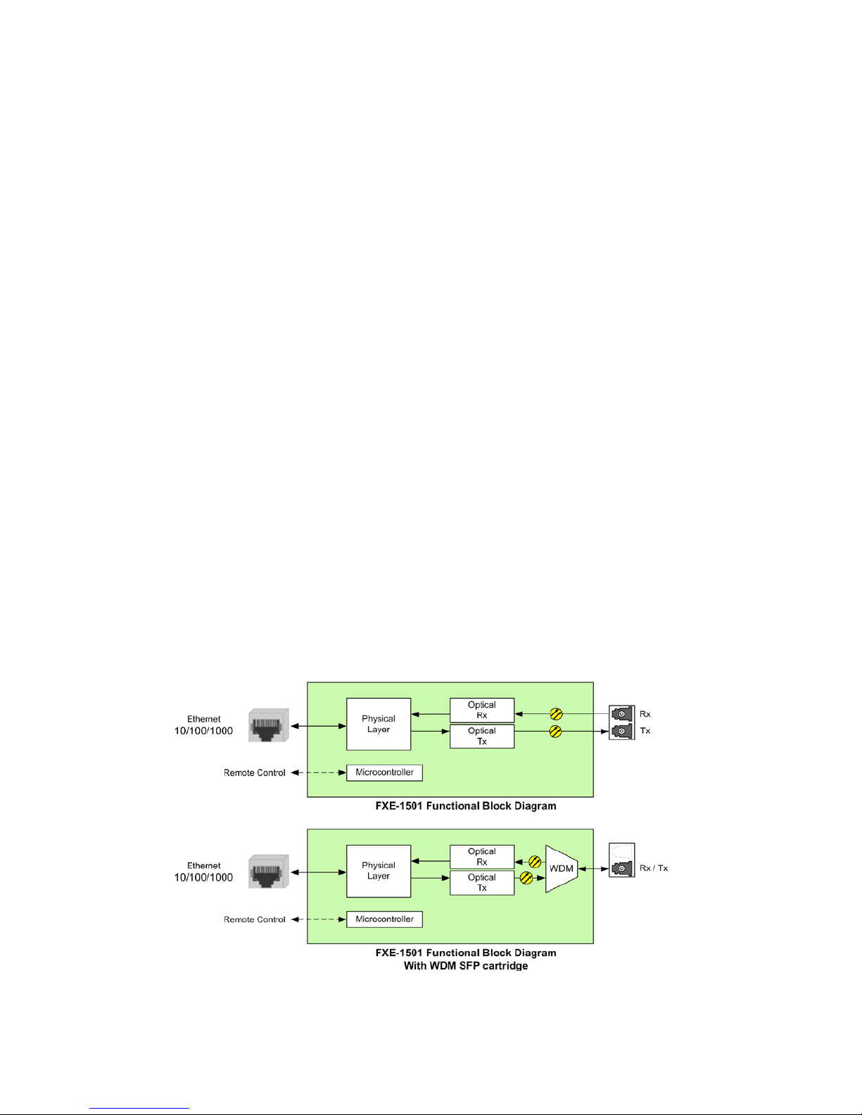
1.3 Block Diagram
The following block diagram shows the functionality of the FXE-1501
Figure 1.1 Functional block diagram of the FXE-1501
Page 6
GUIDE TO INSTALLATION AND OPERATION
2 | FXE-1501
1.4 Front Card-edge Interface
The front card-edge of the FXE-1501 incorporates two
elements:
• Status LED (see section 3.2)
• Select Button (see section 3.3)
Figure
1.2 Front card-edge layout
Select
Status
FXE-1501
Status LED
Select Button
Page 7
GUIDE TO INSTALLATION AND OPERATION
FXE-1501 | 3
2 Installation
2.1 Unpacking
Make sure the following items have been shipped with your FXE-1501. If any of the following items are missing,
contact your distributor or Miranda Technologies Inc.
• FXE-1501 Fiber Ethernet Transceiver
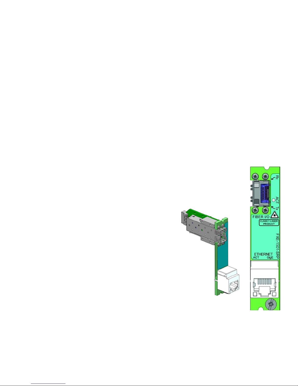
• FXE-1501-SRP Rear Panel (see figure 2.1)
2.2 Installation in the Densité frame
The FXE-1501 and its associated rear connector rear panel are designed for installation in a Densité 2 frame. It is not
necessary to switch off the frame’s power when installing or removing the card.
• With the use of available adapters, this card and its associated rear panel can be installed in a Densité 3 frame.
See the Densité 3 frame manual for details.
2.3 Rear Connector Panel
The FXE-1501-SRP single-slot rear panel, mounted in a Densité 2 or Densité 3 frame, incorporates these connectors:
• One socket for inserting a fiber transm itter/r ec eiver SFP module
• One RJ-45 for connection to the ethernet
It also incorporates status indicators for:
Ethernet Activity: integrated into the RJ45 plug
Ethernet GigE: integrated into the RJ45 plug
Fiber Link Activity: beside the optical SFP socket
Figure 2.1 FXE-1501-SRP Rear Panel
Page 8

GUIDE TO INSTALLATION AND OPERATION
4 | FXE-1501
2.4 Supported SFP Modules
The FXE-1501 supports the use of the following SFP modules:
Standard module, transmission at 1310 nm :
• SFP-ETH-10-S13-LC Ethernet 10 km SFP cartridge / 1310 nm with LC/PC connector
Modules for WDM applications:
• SFP-ETH-10-RT-W13-LC Optical Ethernet WDM cartridge, 1310 nm, LC/PC connector
• SFP-ETH-10-RT-W15-LC Optical Ethernet WDM cartridge, 1550 nm, LC/PC connector
Note: In WDM applications, only a single fiber is used, and both ends of the link must transmit at
different wavelengths. Therefo re , for WDM operation between two FXE-1501 transceivers, one must
be equipped with a W13 SFP module, and the other with a W15 SFP module.
The single fiber must be connected to the T x side of the SFP module (as marked on the FXE-1501
rear panel) at both ends of the link.
Modules for CWDM applications:
• SFP-ETH-10-RT-C27-LC Optical Ethernet CWDM cartridge, 1271 nm, LC/PC connector
• SFP-ETH-10-RT-C29-LC Optical Ethernet CWDM cartridge, 1291 nm, LC/PC connector
• SFP-ETH-10-RT-C31-LC Optical Ethernet CWDM cartridge, 1311 nm, LC/PC connector
• SFP-ETH-10-RT-C33-LC Optical Ethernet CWDM cartridge, 1331 nm, LC/PC connector
• SFP-ETH-10-RT-C35-LC Optical Ethernet CWDM cartridge, 1351 nm, LC/PC connector
• SFP-ETH-10-RT-C37-LC Optical Ethernet CWDM cartridge, 1371 nm, LC/PC connector
• SFP-ETH-10-RT-C39-LC Optical Ethernet CWDM cartridge, 1391 nm, LC/PC connector
• SFP-ETH-10-RT-C41-LC Optical Ethernet CWDM cartridge, 1411 nm, LC/PC connector
• SFP-ETH-10-RT-C43-LC Optical Ethernet CWDM cartridge, 1431 nm, LC/PC connector
• SFP-ETH-10-RT-C45-LC Optical Ethernet CWDM cartridge, 1451 nm, LC/PC connector
• SFP-ETH-10-RT-C47-LC Optical Ethernet CWDM cartridge, 1471 nm, LC/PC connector
• SFP-ETH-10-RT-C49-LC Optical Ethernet CWDM cartridge, 1491 nm, LC/PC connector
• SFP-ETH-10-RT-C51-LC Optical Ethernet CWDM cartridge, 1511 nm, LC/PC connector
• SFP-ETH-10-RT-C53-LC Optical Ethernet CWDM cartridge, 1531 nm, LC/PC connector
• SFP-ETH-10-RT-C55-LC Optical Ethernet CWDM cartridge, 1551 nm, LC/PC connector
• SFP-ETH-10-RT-C57-LC Optical Ethernet CWDM cartridge, 1571 nm, LC/PC connector
• SFP-ETH-10-RT-C59-LC Optical Ethernet CWDM cartridge, 1591 nm, LC/PC connector
• SFP-ETH-10-RT-C61-LC Optical Ethernet CWDM cartridge, 1611 nm, LC/PC connector
Page 9

GUIDE TO INSTALLATION AND OPERATION
FXE-1501 | 5
3 Operation
3.1 Control options
The FXE-1501 can be controlled in two different ways:
• The local control panel and its push-buttons can be used to move through a menu of parameters and to adjust a
basic set of parameters (see section 3.3).
• Miranda’s iControl system can be used to access the card’s operating parameters from a remote computer, using
a convenient graphical user interface (GUI) (see section 3.4).
3.2 Card-Edge Status LED
The status monitor LED is located on the front card-edge of the FXE-1501, and is visible through the front access door
of the DENSITÉ frame. This multi-color LED indicates the status of the FXE-1501 by color, and by flashing/steady
illumination.
The chart shows how the various error conditions that can be flagged on the FXE-1501 affect the LED status.
• If a cell is gray, the error condition cannot cause the LED to assume that status
• If more than one LED status is possible for a particular error condition, the status is configurable.
See Annex 1 on page 17 for details.
• The factory default status is shown by a
The LED will alwa ys show the m ost severe detected error status that it is c onfigured to display, an d in the char t error
severity increases from left to right, with green representing no error/disabled, and flashing red the most severe error.
LED Status
Error Condition
Green
Yellow
Red
Flashing
Red
No errors
No UTP Link
No Fiber Link
No Fiber Module
No Rear
If the LED is Flash ing Yellow, it means that the card is s elected for local control using the Densité frame’s control
panel, or that the card is booting up. See Section 3.3 for details.
3.3 Local control using the Densité frame control panel
3.3.1 Overview
Push the SELECT button on the FXE-1501 card edge (see Section 1.4) to assign the local control panel to operate
the FXE-1501. Use the control panel buttons to navigate through the menu, as described below.
All of the cards installed in a Densité frame are connected to the frame’s controller card, which handles all interaction
between the cards and the outside world. There are no operating controls located on the cards themselves. The
controller supports remote operation via its Ethernet ports, and local operation using its integrated control panel.
Page 10

GUIDE TO INSTALLATION AND OPERATION
6 | FXE-1501
The local control panel is fastened to the front of the
CPU-ETH2 controller card, and when installed is
located in the front center of the frame, positioned in
front of the power supplies. The panel consists of a
display unit capable of displaying two lines of text, each
16 characters in length, an d five pushb utto ns .
The panel is assigned to operate any card in the frame
by pushing the SELECT button on the front edge of that
card.
• Pushing the CONTROLLER button on the
control panel selects the Controller card itself.
• The STATUS LED on the selected card flashes
yellow.
The local control panel displays a menu that can be navigated using the four pushbuttons located beside the display.
The functionality of the pushbuttons is as follows:
[+] [–] Used for menu navigation and value modification
[SELECT] Gives access to the next menu level. When a parameter value is shown, pushing this button once
enables modification of the value using the [+] and [–] buttons; a second push confirms the new value
[ESC] Cancels the effect of parameter value changes that have not been confirmed; pushing [ESC] causes the
parameter to revert to its former value.
Pushing [ESC] moves the user back up to the previous menu level. At the main menu, [ESC] does not
exit the menu system. To exit, re-push the [SELECT] button for the card being controlled.
If no controls are operated for 30 seconds, the controller reverts to its normal standby status, and the selected card’s
STATUS LED reverts to its normal operating mode. If a parameter was changed on the card but not submitted
(SELECT was not pressed) and the 30 second timeout occurs, the parameters will be confirmed as if the SELECT key
had been pressed.
3.3.2 Menu for local control
The FXE-1501 has operating parameters which may be adjusted locally at the controller card interface.
• Press the SELECT button on th e FXE-1501 f ront card edg e to assign the D ensité fram e’s local control pa nel
to the FXE-1501
• Use the keys on the loc al control pa nel to step through the displayed m enu to conf igure and adjust the FXE-
1501.
The complete menu structure is shown in the Annex to this document, beginning on page 17.
Figure
3.1 Densité Frame local control panel
Page 11

GUIDE TO INSTALLATION AND OPERATION
FXE-1501 | 7
3.4 Remote control using iControl
The operation of the FXE-1501 may be controlled using Miranda’s iControl system.
• This manual describes the control panels associ ated w ith the FXE-1501 and their use.
• Please consult the iControl User’s Guide for information about setting up and operating iControl.
In iControl Navigator or iControl Websites, double-click on the FXE-1501 icon to open the control panel.
3.4.1 The iControl graphic interface window
The basic window structure for the FXE-1501 is shown in figure 3.2. The window identification line gives the card type
and the slot number where the card is installed in its Densité frame.
There are three main sections in the window itself, identified in figure 3.2:
Section 1. The top section displays three icons on the left. These icons report the status of the two interface ports of
the FXE-1501, as well as the card control status.
Icon # 1 2 3
Move the mouse over an icon and a status message appears below the icon providing additional information.
If there is an error, the error status message appears in the message area without mouse-over.
• If there are multiple errors, the error messages cycle so all can be seen
• The icon whose status or error message is shown is highlighted with a mauve background
Figure
3-2 FXE-1501 iControl graphic interface window
Page 12

GUIDE TO INSTALLATION AND OPERATION
8 | FXE-1501
The table below describes the various status icons that can appear, and how they are to be interpreted.
• In cases where there is more than one possible interpretation, read the error message in the iControl window to
see which applies.
Table – iControl Status Icon interpretation
Icon #1 – Manual Card Configuration
(green)
Remote card control activated. The iControl interface can be used to operate the card
(yellow)
Local card control active, The card is being controlled using the Densité frame control
panel, as described in section 4. Any changes made using the iControl interface will have
no effect on the card.
Icon #2 – UTP Status
(green)
Carrier detected and locked
• Mouse over the icon to see format details.
(red)
Link down and no activity
No rear
Icon #3 – SFP Status
(green)
Carrier detected and locked.
• Mouse over the icon to see format details
(red)
Link down and no activity
No rear
Section 2. The left portion of the window contains a series of buttons, which become highlighted when they are
selected; the main panel (3) then displays the group’s set of parameters. Each of the groups is described in detail
below.
Section 3. The main panel contains all the parameters specific to the group selected. It may contain several tabs to
help manage the different parameters.
Each of the panels assoc iated with the groups access ed from the buttons in Section 2, and sho wn in Section 3, is
described individually in the following sections.
Page 13

GUIDE TO INSTALLATION AND OPERATION
FXE-1501 | 9
4 Detailed Operat ing Procedure
The basic operating characteristics of the FXE1501 can be adjusted using the Config/Status panel in the iControl GUI,
or the on-board menu using the local control panel.
• Refer to the menu on page 17 for help in accessing the indicated items using the local control panel.
• The relevant section of the iControl GUI is shown here; select the desired option by clicking the appropriate
radio button:
• In all lists of optional values for a parameter, the underlined value is the default value.
• Terminology: UTP = Unshielded Twisted Pair (descriptive of the Ethernet network wiring)
4.1 Network Configuration
4.1.1 UTP Negotiation
When AUTO is selected, The FXE-1501 will communicate with the Ethernet at the highest available rate, and the UTP
Speed and UTP Duplex selections will be disabled (gray).
When MANUAL is selected, the FXE-1501 will communicate with the Ethernet at the rate selected in the UTP Speed
menu (see the next section).
• Available choices: [AUTO, MANUAL]
4.1.2 UTP Speed
Set the Ethernet connection speed to the selected value when MANUAL is selected as the UTP Negotiation option.
• Available choices: [1000, 100, 10]
Note that on the fiber-optic interface, the speed is fixed to 1000.
4.1.3 UTP Duplex
Choose whether to operate the Ethernet connection as a full-duplex or a half-duplex link when MANUAL is selected
as the UTP Negotiation option.
• Available choices: [FULL, HA LF]
Note that FULL is forced when the Ethernet connection speed is 1000
Page 14

GUIDE TO INSTALLATION AND OPERATION
10 | FXE-1501
4.1.4 Jumbo Packet Size
The use of Jumbo Frames, carrying larger packets of data than the original Ethernet frame of 1518 bytes, can
increase system throughput in some cases. The same frame size must be used at both ends of the network, and
because it is non-standard, it must be set explicitly at each end. The default option here is the standard packet size.
• Available choices: [1.5 Kb, 2 Kb, 10 Kb]
4.1.5 Link Loss Forwarding
Link Loss Forwarding is a method of flagging loss of signal on the FXE-1501’s fiber input. When signal loss is
detected, the FXE-1501 turns off its UTP transmitter, allowing the device at the other end of the UTP link to be
immediately aware that there is a problem, and for troubleshooting to be initiated. It also turns off its fiber transmitter,
shutting down the return link. The FXE-1501 at the other end of the fiber link will detect that shutdown if its LLF is
enabled, and the entire system will be shut down. Once the failed link is repaired, the LLF will detect the resumption of
signal, and the entire system will go back into normal operation
When LLF is OFF, the UTP transmitter continues to send out data packets, despite the loss of input data, and the
return fiber link continues to operate normally.
• Available choices: [OFF, ON]
4.2 Alarms
The FXE-1501 signals the user when error conditions are detected. The alarms triggered when an error is detected
are communicated to the user locally using the card-edge status LED on the card itself, and using the Densité frame’s
GPI output. Additional alarm information is communicated through the iControl system.
4.2.1 Alarm configuration using the local menu
For each of the configurable alarms listed in the menu (NO UTP LINK, NO FIBER MODULE, NO FIBER LINK), select
the way in which it will be displayed on the card-edge Status LED:
Available choices: [GREEN, YELLOW, RED, FLASH RED]
For each alarm, select whether it will be reported on the GPI output of the frame controller.
Available choices: [NONE, GPI]
4.2.2 Alarm configuration using iControl
Click on the Alarm Config button on the left of the control panel to open the Alarm Configuration window.
Page 15

GUIDE TO INSTALLATION AND OPERATION
FXE-1501 | 11
This window allows a more comprehensive management of alarms than the menu.
Status / Name This column lists, beginning at the top, all the individual alarms that are available on this card.
Each has a status icon at the left that will be either green (no alarm) or red (the error
condition has been detected and the alarm is ON).
At the bottom are some composite alarms (Card LED and Overall) whose status is
programmed by user selections made in the similarly-named columns
Card LED This column contains user-configurable settings that allow the user to determine the
contribution of each of the individual alarms to the Card LED composite alarm. This alarm
determines the color displayed on the Status LED visible on the front edge of the card.
See below for a description of how to use these settings.
Overall Alarm This column contains user-configurable settings that allow the user to determine the
contribution of each of the individual alarms to the Overall composite alarm. This alarm
determines the color of the status icon at the top left of the iControl panel for this card at the
user’s workstation, and the status icon displayed for this card in other iControl applications
such as iControl Navigator.
See below for a description of how to use these settings.
GSM Contribution This column contains user-configurable settings that allow the user to determine the
contribution of each of the individual alarms to the GSM alarm status for the card. The GSM
(General Status Manager) is a dynamic register of all iControl system alarms, and is also an
alarm provider for external applications. The possible values for this contribution are related
to the Overall alarm contribution:
• If the Overall alarm contribution is selected as Disabled, the GSM alarm contribution
can be set to any available value
• If the Overall alarm contribution is selected as any level other than disabled, the GSM
contribution is forced to follow the Overall Alarm.
Page 16

GUIDE TO INSTALLATION AND OPERATION
12 | FXE-1501
Note that you can force all three composite alarms (Card
LED, Overall, and GSM Contribution) to be the same (and
equal to the Card LED setting) by selecting the checkbox at
the lower left of the window.
• All Overall alarms and GSM contributions for which
there is a Card LED alarm will be forced to match the
Card LED alarm
• All Overall Alarms and GSM contributions for which
there is no Card LED alarm will be forced to Disabled
A warning box will open allowing you to confirm the action,
since it will result in changes to the configuration and there is
no undo function
The Card LED, Overall alarm and GSM contribution columns contain pulldown lists that allow the level of
contribution of each individual alarm to the composite alarm named in the column heading to be set.
Click on the alarm icon to see the available levels; then click on one to select it
The pulldown lists may contain some or all of the following options:
The alarm makes no contribution (black icon)
The alarm is of minor importance (yellow icon)
The alarm is of major importance (orange icon)
The alarm is of critical importance (red icon)
The alarm exists but has no effect (used for composite alarms)
Shortcut: if you click in one of the Set All boxes at the top of a column, you will open a pulldown that lets you assign
a level to all alarms in the column simultaneously.
A composite alarm can assume only one value, which is the value of the most significant of the contributing individual
alarms, i.e. the “worst case”. So, for example, if one alarm is ON and its contribution has been chosen as “Minor”, and
a second alarm is ON whose contribution has been chosen as “Critical”, the composite alarm will assume the “Critical”
status.
Log Events
iControl maintains a log of alarm events associated with the card. The log is useful for troubleshooting and identifying
event sequences. Click in the checkbox to enable logging of alarm events for each individual alarm.
Copy to other cards
Once you have set up the alarms for this FXE-1501, you may copy them to other FXE-1501 cards, saving the work of
setting up each card individually. Proceed as follows:
1. Click the Copy to other cards button at the bottom right of the alarm configuration panel.
The Copy to other cards window opens, showing all other FXE-1501 cards available through the iControl
Navigator you are using.
Page 17

GUIDE TO INSTALLATION AND OPERATION
FXE-1501 | 13
2. Select the checkboxes in the column headed All for the cards to which you want to transfer the alarm settings
from this card. If you want to transfer to all of them, you can click the All checkbox in the column heading
instead of selecting them all individually.
3. Click Copy.
The alarm settings will be copied. The Transfer Status column will show the status of the transfer process for
each destination card.
If a transfer fails, it may be because the source card and destination card are not running the same firmware
version. Verify the firmware version of both cards by looking at VERSION in the menu, or by clicking Details…
in the iControl Info panel.
5 Addit ional Functions
5.1 Factory Default S ettings
The FXE-1501 maintains a file of factory-specified settings for all variable parameters.
• These are the values that are underlined in the local menu as shown on page 17.
If necessary, these settings can be restored on this FXE-1501.
Using the local menu:
• Navigate to FACTORY DEFAULT and select [RESTORE]
Using iControl:
• Open the Factory / Presets panel, and click “Load Factory”
5.2 System Information
Information about the current state of the FXE-1501 card is available to the user.
In the local Menu:
• Navigate to VERSION – FXE-1501 to see the firmware version
• Navigate to VERSION – CPU BUILD to see the CPU build version
Page 18

GUIDE TO INSTALLATION AND OPERATION
14 | FXE-1501
In iControl:
Click the Info button to open the Info panel
When the FXE-1501 is included in an iControl
environment, certain information about the card should be
available to the iControl system. The user can enter labels
and comments that will make this card easy to identify in a
complex setup. This information is entered into data boxes
in the Info control panel.
Label: Type the label that is shown for this
FXE-1501 when it appears in iControl
applications
Short Label Type the short-form label that iControl
uses in some cases (8 characters)
Source ID Type a descriptive name for this FXE-
1501
Comments: Type any desired text
The remaining data boxes show manufacturing information
about this card, including the type of rear panel and the
type of SFP module that is installed.
The service version is shown in the main panel, but more detailed
information about the device is shown in the Details window. Click
Details… to open the wi ndo w.
Click Advanced… to open a window displaying the Miranda Long
ID, which is the address of this FXE-1501 in the iControl network.
Page 19

GUIDE TO INSTALLATION AND OPERATION
FXE-1501 | 15
Remote System Administration – opens the Joining Locators window, which
lists remote lookup services to which this FXE-1501 is registered
Add: Force the iControl service for this FXE-1501 to register itself on a
user-specified Jini lookup service, using the following syntax in the data
box:
jini://<ip_address>
where <ip_address> is the ip address of the server running the lookup
service, e.g.:
Remove: select one of the services listed in the window by clicking on it, and click Remove to open a query box
allowing you to delete it from the window.
Page 20

GUIDE TO INSTALLATION AND OPERATION
16 | FXE-1501
6 Specifications
UTP port:
Connector: RJ-45
Compliant To: 10BaseT/100BaseTx/1000BaseT with IEEE 802.3, IEEE 802.3u and IEEE 802.3ab, speed
auto sensing and auto MDI/MDI-X.
Jumbo Frame: Supports up to 10000 bytes.
SFP Port:
Connector: SFP compliant
Compliant to: IEEE 802.3z, 1000 Base-LX/SX
Overall:
Form factor: Single slot Densité 2
Power: Maximum 3 watts
Page 21

GUIDE TO INSTALLATION AND OPERATION
FXE-1501 | 17
ANNEX 1 – FXE 1501 User Interface (local menu structure)
STATUS
NO REAR, FXE-1501-SRP-F
NO FIBER MODULE, BRAND and REFERENCE
NO UTP LINK, UTP [10/100/1000] [FULL/HALF]
NO FIBER LINK, FIBER LINK OK
UTP NEGOTIATION
[AUTO , MANUAL]
UTP SPEED *
[1000, 100, 10]
UTP DUPLEX **
[FULL, HAL F]
JUMBO PKT SIZE
[1.5KB, 2KB, 10KB]
LINK LOSS FWD
[OFF, ON]
CONFIG ALARMS
NO UTP LINK
ALARM LEVEL
[GREEN, YELLOW, RED, FLASH RED]
ALARM REPORT
[NONE, GPI]
NO FIBER MODULE
ALARM LEVEL
[GREEN, YELLOW, RED, FLASH RED]
ALARM REPORT
[NONE, GPI]
NO FIBER LINK
ALARM LEVEL
[GREEN, YELLOW, RED, FLASH RED]
ALARM REPORT
[NONE, GPI]
VERSION
FXE-1501: XXX
CPU BUILD: XXX
FACTORY DEFAULT
[RESTORE]
Note:
* This menu appears only if NEGOTIATION is set to MANUAL
** This menu appears only if NEGOTIATION is set to MANUAL, and if UTP SPEED is not 1000.
Page 22

GUIDE TO INSTALLATION AND OPERATION
18 | FXE-1501
ANNEX 2 – Installing the Optical Interface
Installing and removing the Fiber I/O interface cartridge requires special care. This annex describes the process.
The FXE-1501 rear panel incorporates a fiber optic interface. The interface consists of two parts:
• A socket on the rear panel into which an SFP interface module is plugged
• An SFP (Small Form-factor Pluggable) module into which the optical fibers are plugged, and which incorporates
the optical/electrical interface
Cautions and Warnings
SFP Transmitter modules contain a class 1 laser, which emits invisible radiation whenever the module is
powered up. Because the SFP is hot-swappable, the module may be powered up as soon as it is installed.
DO NOT LOOK INTO AN OPERATING SFP MODULE’S CONNECTORS, AS EYE DAMAGE MAY RESULT.
The SFP module is sensitive to electrostatic discharge (ESD). It is recommended that you use an ESDpreventive wrist strap grounded to the Densité chassis while handling the SFP module.
SFP modules are subject to wear, and their useful lifetime is reduced each time they are inserted or removed.
Do not remove them more often than is absolutely necessary.
Never remove or install an SFP module with the fiber optic cables connected. Damage to the cables could
result.
The presence of dust and debris can seriously degrade the performance of an optical interface. It is
recommended that you insert a dust plug into the SFP module whenever a fiber optic cable is not connected.
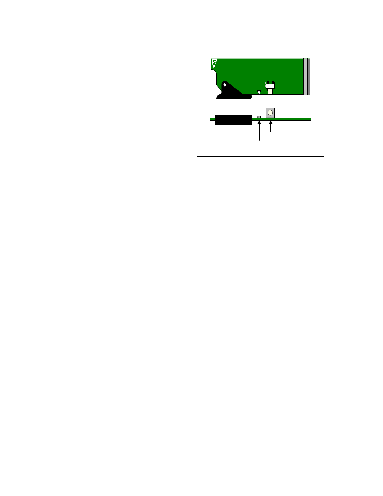
Installing an SFP module
1. Make sure that the bale clasp lever is in the closed position
2. Position the SFP module so that the recessed slot is lined up with the
tab side of the socket.
Page 23

GUIDE TO INSTALLATION AND OPERATION
FXE-1501 | 19
3. Slide the module straight into the socket, and push gently until it
clicks into position.
Connecting the fiber optic cables
1. Remove the dust plug from the SFP module if present
2. Verify that the exposed end of the optical fiber in the LC
connector is clean
• Carefully remove any debris if necessary.
3. Plug the LC-terminated fiber optic cable into the SFP module
Removing the fiber optic cables
1. Grasp the LC fiber optic connector that is plugged into the SFP module, and pull it straight out to disengage
the optical fiber from the SFP.
• Never pull the fiber optic cable itself, as catastrophic damage may occur.
2. Insert a dust plug into the SFP module.
Removing the SFP module
1. Move the bale clasp lever to the open position.
2. Grasp the SFP module between your thumb and forefinger, and
pull it straight out of the slot.
• Do NOT pull on the bale clasp lever to remove the module, as
it is easily damaged
• You may find that you need to wiggle the module, or perhaps
push it into the slot a bit, before it will release and slide out.
3. Insert a dust plug into the SFP module.
 Loading...