

Page 1
QuickStart Guide
CR Series Compact Router
and Accessories
Product Summary
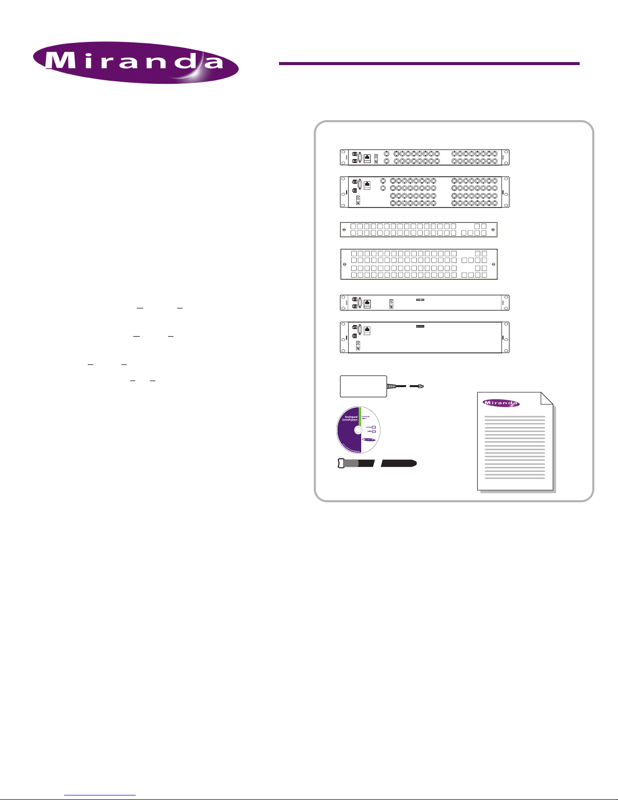
You will have received one or more routers, control panels,
remote panel modules, power supplies, and a CD that
includes documentation and software. See Figure 1.
The CR Series Compact Router family includes 1RU and 2RU
routers, control panels, and remote panel modules.
The product family includes HD, SD, “3Gig,” and analog
video routers. It includes AES and analog audio routers and
machine control routers (a.k.a. port routers).
The 1RU control panels and routers include several formats:
16×16, 16×4, 16×2, and 32×1. The 2RU control panels and
routers include 2 format: 32×32, and 32×4.
The product names indicates their size and type. For example,
CR3204-AES indicates a C
inputs and 4 AES outputs.
Similarly, a CP1602 is a C
sources to 2 destinations (by default).
“RP” means R
emote Panel module.
A CR16-P R is a 16-port Port Router (machine control router).
See Product Set, on page 8, for a complete list.
The 16×16 routers can switch any of 16 inputs to any of 16
outputs and the 32×32 routers can switch any of 32 inputs to
any of 32 outputs. The 16×4 router switches 16 inputs to 4
outputs. The 32×4 routers switch 32 inputs to 4 outputs. All
the router matrices are fully non-blocking.
The machine control routers are bidirectional, point-to-point
routers, transmitting serial data under RS-422, up to 1 Mb/s.
All other compact routers are unidirectional, X/Y routers.
A CR Series control panel can be mounted on the front of a
router or a remote panel module and provides direct visual
and tactile control of the router. However, any of the routers
can also operate without a control panel under control of an
automation system.
The CR Series routers can be connected on an Ethernet network or used with the NV9000 Router Control System.
A CR Series “remote panel module” is a device that sends
commands to a network of routers and monitors the status of
the routers. A remote panel module supports a control panel.
The panel is then called “remote” because it can be located at
a distance from the routers.
A network also allows “local” or “captive” control panels.
Captive control panels are those that mount on a router.
The CR Series also includes configuration software that
allows you to make the most of your compact router system,
and button legend templates in several formats.
ompact Router having 32 AES
ontrol Panel that lets you switch 16
Figure 1. Package Contents
Router(s)
1RU
2RU
Control Panel(s)
1RU
2RU
DIP
1ON23 4 5 67 8
DIP
1ON23 4 5 67 8
Power suppl(ies)
1 software and
documentation
disk
1 power cord retention strap
for each power supply
Quick-Start Guide
(this document)
Remote Panel
Module(s) 1RU
2RU
Routers
All CR Series routers except machine control routers have
connectors for bi-level or tri-level video reference (sync) signal and will switch according to SMPTE RP168-2002.
We recommend using a video reference. The video reference
is loop-through: you can pass the video reference on to other
routers or terminate the reference at any point.
Each router has two power inputs for redundancy, a grounding lug, an RS-485/422 automation port, and an Ethernet
port.
In addition, each analog audio router has DB25 connectors for
I/O. See Figure 5. Each machine control router has RJ-45 connectors for I/O. See Figure 6. All other routers have two 75Ω
BNC connectors for I/O. See Figure 4.
Each router saves its current state (crosspoint connections,
locks, etc.) in non-volatile memory.
Product Number: QG0003-06 Revision: 1.5; Date: 27 Mar 09 1
Page 2
CR Series Compact Router
Source
Dest
12345
DST
LOCK
PNL
LOCK
LVL1LVL2LVL3LVL
4
“3Gig” Video Routers
The CR1616-3Gig and CR3232-3Gig video routers support
2.97 Gb/s operation and several SWB and SD data rates.
HD Video Routers
The CR1616-HD, CR1604-HD, and CR3232-HD are “SWB”
(super wide band) routers. They support a wide range of SD
and HD serial data rates. They support DVB-ASI.
SD Video Routers
The CR1616-SD, CR1604-SD, and CR3232-SD support a wide
range of SD serial data rates. They support DVB-ASI.
AES Audio Routers
The CR1616-AES and CR3232-AES routers support AE3id
audio. The AES routers will switch in sync with a video reference if one is available and will free-run if no reference is
available. If a video reference is not present, the router is
asynchronous and it passes input signals straight through
without any processing.
Analog Video Routers
The CR1616-AV and CR3232-AV routers switch NTSC (525i)
and PAL (625i) formats.
Analog Audio Routers
The CR1616-AA and CR3232-AA routers switch analog audio
signals. They pass the signal straight through and do no
internal processing.
The CR1616-AA switches 16 stereo pairs and the CR3232-AA
switches 32 stereo pairs. The analog routers do not perform
mono switching.
Machine Control Routers
The CR16-PR and CR32-PR routers (a.k.a. port routers) switch
machine control streams or serial data streams up to 1Mb/s.
The CR16-PR has 16 ports and the CR32-PR has 32. The ports
are bidirectional, RS-422. Connections are point-to-point.
Machine control ports can be configured in several ways.
Software is required for port configuration.
Software
CRSC is a relatively new software tool that helps you create
efficient, more easily used router networks. It configures both
routers and remote panel modules.
CRConfig is nearly obsolete, but included on the CD. It is still
useful for stand-alone networks.
Operating Modes
CR Series routers can be used in 4 general modes:
• A stand-alone router, with an attached control panel.
• A stand-alone network of routers and remote panels.
• A “CRSC” network of routers and remote panels.
• An NV9000 network: one or more routers controlled by an
NV9000 router control system.
These modes determine the behavior of CR Series products
and affect the meaning of CR Series features.
For example, routers and control panels in a CRSC network
are highly configurable. In other modes, they are not configurable. There are many other significant differences.
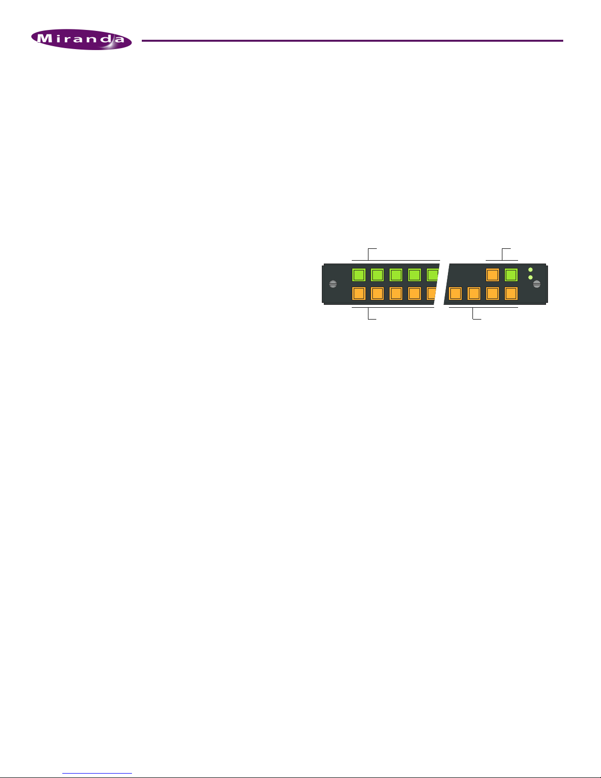
Control Panels
These are the available control panels.
CP1616 CP1604 CP1602 CP3232 CP3204 CP3201
This example is a 16×16 control panel (CP1616):
Source buttons... Lock buttons
Destination buttons...
On any control panel, the two buttons at the top right are
locks:
• Destination Lock. Prevents accidental re-routing of one or
more destinations.
• Panel Lock. Protects accidental use of the entire panel.
In a stand-alone system, control panels have source buttons,
destination buttons, lock buttons, and level buttons, as
shown above. The numbered buttons on a control panel correspond to the numbering of the connectors at the rear of a
router (of the same size).
In a CRSC network, control panels are configurable: any button (except the lock buttons) can be configured independently as a source, destination, salvo, or level button.
(Salvos are executable lists of low-level “takes.”)
In a stand-alone system, the 4 function buttons just below
the lock buttons are level selection buttons. Routers are
assigned levels from 1 to 4. A control panel in the network
illuminates level buttons for each router in the network.
Users may select any or all of the levels at any time.
In a CRSC network, levels are router partitions. Up to 8 levels
can be defined. Level selection is governed by 3 panel configuration modes: standard mode, enhanced mode with “hold,”
and enhanced mode without “hold.”
In a CRSC network, control panels route signals between
“devices.” Devices are configured as sets of related inputs or
outputs.
In a stand-alone system, control panels switch inputs and out-
puts only, either on a single level or multiple levels.
A stand-alone router requires a control panel (or automation). A stand-alone network of routers requires either captive
panels or remote panels. A CRSC network requires remote
Level selection buttons
2 Product Number: QG0003-06 Revision: 1.5; Date: 27 Mar 09
Page 3
CR Series Compact Router
panel(s) but allows the presence of captive panels. An
NV9000 router control system does not require CR Series control panels. (It probably uses NV96xx control panels.)
Remote Panel Modules
CR Series remote panel modules (RP16, RP32) resemble CR
Series routers in size and form, but they have only communication connections and no I/O. A remote panel module controls routers in the network. In a CRSC network, the remote
panel module is the “intelligence” of the network.
A compact router network may have up to 16 remote panels
and up to 4 routers of mixed type.
Software
CRSC is a relatively new software tool that helps you create
efficient, more easily used router networks. It configures both
routers and remote panel modules.
CRSC allows the following.
• View and control the IP addresses of devices in the net-
work.
• Create router partitions (i.e., levels).
• Completely configure remote panels.
• Monitor router crosspoints.
• Update firmware.
• View and clear locks.
Because CRSC offers so much capability, we recommend it as
the preferred operating mode.
CRConfig is obsolete, but included on the CD. It is still useful
for stand-alone networks.
CRConfig is a diagnostic and configuration application that
allows you to do the following:
• Update router software and firmware, if the need arises.
• Determine what devices are present in a network.
• Perform simple single-level takes.
• Configure the ports of a machine control router.
Either CRSC or CRConfig is required for the configuration of
machine control router ports.
Installation
Software and Documentation
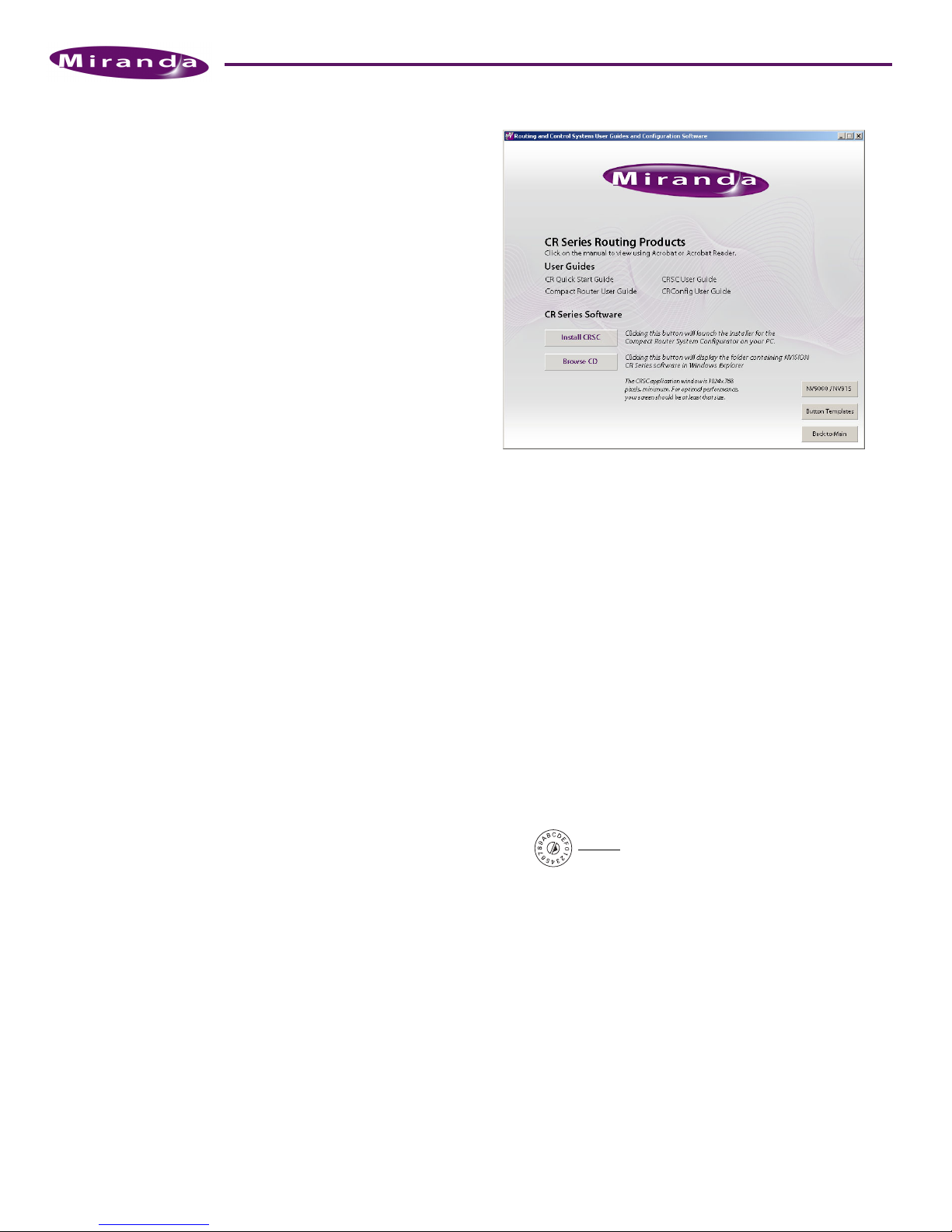
Insert the supplied CD (SB0033) in your CD drive. It will
autoplay in a few seconds. On the first screen you see, click
‘CR Series Routing Products’.
The CR Series screen displays:
You can choose from 4 options at any time:
• Install CRSC.
• Obtain documentation.
• Open a button template.
• Browse the CD.
To i nst all the CRSC software, click ‘Install CRSC’ and follow
the simple steps when the installer appears. The installation
process takes less than a minute. Optionally, place a “shortcut” on your PC desktop.
You can i nst all CRConfig by browsing the CD and doubleclicking the installer (CRConfig_Install.exe). Follow the simple instructions.
Rotary Switches
Every router and every remote panel module has a 16-position rotary switch. The rotary switch is used in stand-alone
networks and NV9000 networks (1) to set the device’s IP
address and (2) for routers, to set the router’s level.
Position 0 is at the right.
FRAME ID
It is used in CRSC networks to set a device’s initial IP address.
You can use CRSC to change IP addresses and levels to more
suitable values once the routers and remote panel modules
are in the network.
Use a small screwdriver to make adjustments. Turn the switch
so that the arrow points to the setting number. The numbers
are in hexadecimal, where the letters A–F represent the numbers 10–15. (You might need to remove a control panel from
the router or remote panel module to access the rotary
switch.)
After you make an adjustment, turn the power to the router
(or remote panel module) on again.
Product Number: QG0003-06 Revision: 1.5; Date: 27 Mar 09 3
Page 4

CR Series Compact Router
If you set the rotary switch to position 0, the router or remote
panel module to reset to its factory default settings when you
cycle power. When you set the rotary switch to a non-zero
position, it retains its settings.
We recommend always setting a device to a non-zero position
while it is in use. Although it is possible to use device with a
zero switch setting, if you lose or remove power, it will reset
and lose its configuration.
Stand-Alone Routers
For a single router, you may set the rotary switch on the
router to any non-zero position.
Stand-Alone Networks
You may have up to 4 routers and up to 16 remote panel modules in a stand-alone network.
Set the rotary switches as follows.
For routers, the rotary switch sets both the router’s IP address
and the router’s level. For each router, choose a switch position from 1 to 4:
Level (1–4) = switch setting.
Subnet address = switch setting + 100.
The IP address is 192.168.2.address. Thus, subnet addresses for
routers range from 101 to 104 and correspond to router levels
1–4. Each router’s rotary switch setting must be unique.
The switch settings of remote panel modules must also be
distinct. For each remote panel module, choose a switch position from 0 to F:
Subnet address = switch setting + 50.
The IP address is 192.168.2.address. Thus, subnet addresses for
remote panel modules range from 50 to 65.
S Remote panels with switch position 0 will reset to the factory
default if power is removed.
Figure 2. Router Network
optional
Control Panel
Video Ref.
Router
Router
Router
Ethernet
Switch
optional
Config. PC
Remote Panel
Remote Panel
Set the rotary switches as follows.
For routers, the rotary switch initially sets the router’s IP
address. For each router, choose a switch position from 1 to F:
Default level = switch setting.
Default Subnet address = switch setting + 100.
The default IP address is 192.168.2.address. Thus, default subnet addresses for routers range from 100 to 115. Each router’s
rotary switch setting must be unique in that range.
Once the routers are established on the network, you can use
CRSC software to override their IP addresses and assign levels,
eliminating the dependence on the rotary switch position.
The switch settings of remote panel modules must also be
distinct initially. For each remote panel module, choose a
switch position from 0 to F:
Default subnet address = switch setting + 50.
The default IP address is 192.168.2.address. Thus, subnet
addresses for remote panel modules range from 50 to 65.
You can use CRSC software to reassign the IP addresses of
remote panel modules too.
S Remote panels with switch position 0 will reset to the factory
default if power is removed.
Router Control System
If you have an NV9000 or NV915 router control system, the
rotary switch setting designates the router’s IP address (and
level) as for stand-alone routers. Refer to your Compact Router
User’s Guide for details.
You can also use CRSC to designate IP addresses for an
NV9000 or NV915 network.
Networked PC
Configuration software is optional in many cases, unless you
have machine control routers to configure or you wish to
build a CRSC network.
If you want to use either CRSC or CRConfig, your PC must be
assigned an IP address on the same subnet as your routers and
remote panel modules.
Follow these steps to configure your PC’s IP address:
1) Launch ‘Settings>Network Connections’ from your PC’s
Start menu. The following window appears:
CRSC Networks
You may have up to 8 levels (but a maximum of 4 routers) and
up to 16 remote panel modules in a CRSC network.
You can have multiple independent CRSC networks. CRSC
can detect (and manage) them if your configuration PC has
suitable network connections. Multiple networks are then
called subnets. CRSC handles one subnet at a time.
4 Product Number: QG0003-06 Revision: 1.5; Date: 27 Mar 09
Page 5

CR Series Compact Router
2) Double-click ‘Local Area Connection’. Then, choose the
‘General’ tab and click ‘Properties’.
3) Select ‘Internet Protocol (TCP/IP)’. Click ‘Properties’ again:
Leave the DNS fields blank. Advanced users may use different subnet forms.
5) Click OK to finish.
Control Panels
Attach a control panel to a router or remote panel module by
placing the control panel in position, mating the connectors
on the two pieces. This requires only minimal force. Then,
tighten the knurled screws so the assembly is secure. See Figure 3.
S A 1RU control panel cannot connect to a 2RU device and vice
versa.
Routers and remote panel modules ship with a cover plate
over the control panel connector. You must remove the cover
plate before mounting the control panel. We recommend
that you leave the cover plate in place if you do not plan to
use a control panel.
You can install button legends at this (or any) time. Button
legend templates are included on your CD. See Button Legends
on page 7.
Rack Mounting
Place the router (or router assembly) in the rack where you
want it, aligning the screw holes with holes in your rack
frame. Secure the router using your screws, nuts, and washers,
as required. See Figure 3.
Mount remote panel modules the same way.
4) Select ‘Use the following IP address’ and enter the IP
address for your PC. Use the default subnet mask.
The subnet mask should usually be 255.255.255.0. Any IP
address will suffice as long as it is not the same as the
address of any router or remote panel module. We recommend you avoid the ranges 100–115 and 50–65.
Figure 3. Rack mount
Control Panel
Connector
CR1616-HD
Digital Video Router
Source
1234567 8910111213141516
Dest
CR3232-AES
Digital Audio Router
Connector Cover Plate Rotary Switch
Rotary Switch
FRAME ID
PS1
PS2
CP1616
For the 1RU routers (or remote panel modules), the mounting
holes are spaced 1.25″ (31.75mm) vertically and allow
approximately 1/8″ (3 mm) of play horizontally.
For the 2RU routers (or remote panel modules), the 3 mounting holes on each side are spaced 1.25″ (31.75 mm) an d 1. 75″
(44.45mm) (overall, 3.0″or 76.2 mm) vertically and also
allow approximately 1/8″ (3 mm) of play horizontally.
S Because the routers are small, you might not have enough space
to reach behind the router and make I/O connections. In that
case, make I/O connections first and save mounting until last.
PS1
PS2
Product Number: QG0003-06 Revision: 1.5; Date: 27 Mar 09 5
Page 6

CR Series Compact Router
Automation Port
If you intend to use the router in an automation system, connect the 9-pin serial port to a serial port of your system. Contact Miranda for more information about automation.
The communication protocol is RS-422 or RS-485 for routers
and is not available for remote panel modules.
I/O Cables, Video Reference Cable
The analog audio routers have DB25 connectors. The
machine control routers have RJ-45 connectors. The other
routers have BNC connector. See figures 4, 5, and 6.
S If your routers are in an NV9000 router control system, the con-
figuration you create for your NV9000 system will include your
device connections.
Connect the video reference input. (Doing this is optional,
but recommended.) This connection is loop-through, nonterminating. Be sure to terminate the output of the last connector in the series with a 75Ω BNC terminator. See Figure 4.
S The AES routers require a reference to operate in synchronous
mode. SDI routers require a reference to perform switches in
accordance with SMPTE RP168.
S The machine control routers do not have video reference connec-
tors.
In stand-alone networks, devices that send and receive signals on multiple levels should be connected to the same input
or output on all the routers that service those levels. Otherwise, multi-level operations will produce unwanted results.
In a CRSC network, there is no such restriction. Connections
are made on the basis of router levels and panel design. (The
connections you will make are actually defined during panel
configuration.)
Making the connections for analog audio might require custom cabling (because of the DB25 connectors). Making the
connections for machine control routers might also require
custom cabling because most controlled “machines” use DE9
connectors.
Ethernet Connections
If you have a router network, connect the router to your
Ethernet switch using CAT5 Ethernet cable (with RJ-45 connectors).
Similarly connect your remote panel modules to your Ethernet switch.
Similarly connect your configuration PC to your Ethernet
switch if you intend to use either CRConfig or CRSC.
Power and Ground
Connect the grounding lug to earth ground. Use copper cable
from 14–6 AWG. See figures 4, 5, or 6.
Ethernet
Video
Ref
I/O
Primary
Power
Automation
Redundant
Power
GND
I/O
Figure 4. Router connections (BNC)
Automation
Primary
Power
Ethernet
I/O
WC0053 or
equiv. cable
I/O
Inputs
Outputs
WC0053 or
equiv. cable
Redundant
Power
Primary
Power
Redundant
Power
GND
Automation
Ethernet
Video
Ref
Reference
Termination
Video
Ref
GND
Figure 5. Router connections (DB25)
Automation
Power
Power
Ethernet
GND
...Ports...
...Ports...
Primary
Redundant
Figure 6. Router connections (RJ-45)
Plug the 4-pin connectors of your power supplies into PS1 or
PS2, or both. Insert the AC plugs into an AC wall socket or
other source of AC power.
(There is no on-off switch. Each router requires at least one
power supply and one AC outlet for each power supply.)
Control panels receive power from the router or remote panel
module on which they are mounted.
6 Product Number: QG0003-06 Revision: 1.5; Date: 27 Mar 09
Page 7

CR Series Compact Router
Configuration
For many stand-alone routers with a control panel, or for a
stand-alone network of routers, there is very little to configure,
beyond setting the rotary switches. Machine control routers
are the exception: you must use software (CRConfig or CRSC)
to set the port types according to the equipment you have
connected to the ports.
For compact routers in a NV9000 system, the configuration is
defined in the NV9000 system. There are many options to
consider. Refer to your User’s Guide or contact Miranda for
information regarding router control systems or automation.
Rotary Switch
As directed under Installation, set each router’s 16-position
rotary switch (on the front face of the router) to a non-zero
position. Also set each remote panel module’s rotary switch
as directed under Installation.
Button Legends
You may customize your control panel buttons with your
own button legends. Create your own legends using a publishing or graphics program. You can use the button legend
templates supplied on the CD. The button legends should be
no larger than 0.40″ × 0.40″ (about 1cm×1cm). The buttons
in the templates are 0.375″ square.
Print your legends on clear plastic in an array and cut them
apart with scissors or a straight edge and blade. The clear plastic button caps are easy to remove. Simply pull them off using
finger pressure, insert the new legend in the cap, and replace
the cap.
Startup
CRSC
S CRSC requires that routers and remote panel modules be updated
with CRSC-compatible firmware. If you want to create a CRSC
network, you should perform a firmware update before proceeding.
The CRSC User’s Guide is moderately long and the software is
complex and requires careful study.
To l aunch CRSC, double-click the application or a shortcut to
the application, or choose
Programs > NVISION > Compact Router System Configurator
from the Windows Start menu.
The default pathname for the application is
C:\Program Files\NVision\Compact Router System Configurator\
CrConfigurator.jar
After launching CRSC, click ‘CR Series Ethernet Settings’ to
scan your network for routers and remote panel modules.
CRConfig
The CRConfig User’s Guide is brief and the software is simple
and very easy to use. Please refer to this document if you need
instructions.
To l aunc h CRConfig, double-click the application or a short-
cut to the application, or choose
Programs > NVISION > CompactRouter Config
from the Windows Start menu. The default pathname for the
application is
C:\Program Files\NVision\NV_CompactRouter\
CompactRouter
After launching CRConfig, click ‘Find CR Family Routers’ to
scan your network for routers and remote panel modules.
CRConfig makes entries in its device “tree.”
Config.exe
To start a router or remote panel module, connect the 4-pin
connector from the power supply to PS1 or PS2. If you are
using two power supplies for redundancy, connect one to PS1
and the other to PS2. Then plug the power suppl(ies) into AC
power outlet(s).
If you have connected your routers and remote panel modules to a power bus, toggle its on/off switch.
At power-up, the router or remote panel module restores its
previous operational state, unless its rotary switch is at position 0. In that case, the device reverts to its factory-default
state.
If you want to use CRConfig or CRSC, you may launch it or terminate it at any time. Typically, you double-click a desktop
icon to launch the software.
Control panels (attached to routers or remote panel modules)
restart with their Panel Lock button bright red. Simply press
the Panel Lock button to clear the lock.
Product Number: QG0003-06 Revision: 1.5; Date: 27 Mar 09 7
Click on a router in the device tree to select the router. The
current state of the crosspoint matrix in that router is displayed. Click ‘Refresh Crosspoints’ to update the display at
any time.
Other Topics
Mixed Router Types
Compact routers come in different sizes and types. A network
can include a mix of different routers.
Page 8

CR Series Compact Router
When a control panel is attached to a remote panel module
in a network of mixed router types, the number of source buttons may differ from the number of inputs on a particular
router.
In a stand-alone or NV9000 network, if there are more remote
source buttons than router inputs, the extra source buttons
do nothing for that router. If there are fewer source buttons
than inputs, the extra inputs cannot be controlled from that
control panel.
The same holds true for destination buttons and outputs.
That condition is not true for CRSC networks. Source (and
destination) buttons control assigned router inputs (and outputs).
The result of a machine control take is different from the
result of a video or audio take. Operators should be aware of
the difference. Refer to the appropriate user’s guide for
details.
Cabling
Note: The SDI routers feature active cable equalization that
allows SD signal recovery up to 400m, HD signal recovery up
to 150m using Belden 1694A cable, and “3Gig” signal recovery up to 100m.
Networks require a customer-supplied Ethernet switch and
Ethernet cable.
Product Set
The CR Series Compact Router family includes 1RU and 2RU
routers, control panels, and remote panel modules.
2RU Routers
CR3232-3Gig
CR3232-HD
CR3232-SD
CR3232-AES
CR3232-AV
CR3232-AA
CR32-PR
CR3204-3Gig
CR3204-HD
CR3204-SD
CR3204-AES
CR3204-AV
CR3204-AA
Remote Panel Modules Corresponding Control Panels
RP16
RP32
32×32, “3Gig” video
32×32, HD video
32×32, SD video
32×32, AES3id audio
32×32, Analog video
32×32, Analog audio
32-Port Machine Control
32×4, “3Gig” video
32×4, HD video
32×4, SD video
32×4, AES3id audio
32×4, Analog video
32×4, Analog audio
1RU
2RU
CP1616 , CP16 04, CP 1602, CP32 01
CP3232, CP3204
These are the available control panels.
Panel Size Inputs Outputs Function Buttons
CP1616 1 RU 16 16 6
CP16 04 1 R U 16 4 6
CP16 02 1 R U 16 2 6
CP3201 1 RU 32 1 6
CP3232 2 RU 32 32 12
CP3204 2 RU 32 4 12
Contact Information
Contact Miranda if you need information about NVISION
router control systems or third-party automation systems.
1RU Routers
C R1616 -3 G ig
C R1616 -H D
C R1616 -S D
C R1616 -A ES
C R1616 -AV
C R1616 -A A
CR16-PR
CR1604-3Gig
CR1604-HD
CR1604-SD
CR1604-AES
CR1604-AV
CR1604-AA
16× 16, “3Gi g” vide o
16×16, HD video
16× 16, SD vid eo
16× 16, AES3 id audi o
16× 16, Analo g vide o
16×16, Analog audio
16- Port Mac hine Co ntrol
16× 4, “3Gi g” vide o
16×4, HD-SDI video
16× 4, SD-SD I vide o
16× 4, AES3 id audi o
16× 4, Analo g vide o
16× 4, Analo g audi o
www.miranda.com
In the Americas, call toll-free +1-800-224-7882 (9 am to 9 pm EST)
In Europe, the Middle East, African or the UK, (9 am to 6 pm, GMT)
call +44 (0) 1491 820222
In France, call +33 1 55 86 87 88 (9 am to 5 pm, GMT + 1)
In Asia, call +852-2539-6987 (9 am to 5 pm, GMT + 8)
In China, call +86-10-5873-1814
Miranda Technologies, Inc. Tel: 514-333-1772
3499 Douglas B. Floreani Fax: 514-333-9828
Montreal, Quebec
Canada H4S 2C6
Find warranty, RMA notice, tech support, and other notices in the
User’sGuide. Specifications are subject to change without notice. © 2008
Miranda Technologies, Inc. All Rights Reserved. NVISION is a registered
trademark of Miranda Technologies, Inc. All other trademarks are the
property of their respective owners.
8 Product Number: QG0003-06 Revision: 1.5; Date: 27 Mar 09
 Loading...