

Page 1

DENSITÉ series
CPU-ETH2
Enhanced Ethernet Controller Card
Guide to Installation and Operation
M659-9900-101
3 May 2013
Miranda Technologies
3499 Douglas-B.-Floreani
St-Laurent, Québec, Canada H4S 2C6
Tel. 514-333-1772
Fax. 514-333-9828
www.miranda.com
© 2013 Miranda Technologies
USO RESTRITO
Page 2

GUIDE TO INSTALLATION AND OPERATION
CPU-ETH2
Electromagnetic Compatibility
This equipment has been tested for verification of compliance with FCC Part 15, Subpart B requirements for
Class A digital devices.
NOTE: This equipment has been tested and found to comply with the limits for a Class A digital device, pursuant to
part 15 of the FCC Rules. These limits are designed to provide reasonable protection against harmful interference
when the equipment is operated in a commercial environment. This equipment generates, uses, and can radiate
radio frequency energy and, if not installed and used in accordance with the instruction manual, may cause harmful
interference to radio communications. Operation of this equipment in a resid ential area is likely to cause harmful
interference in which case the user will be required to correct the interference at his own expense.
This equipment has been tested and found to comply with the requirements of the EMC directive
2004/108/CE:
• EN 55022 Class A radiated and conducted emissions
• EN 55024 Immunity of Information Technology Equipment
• EN 61000-3-2 Harmonic current injection
• EN 61000-3-3 Limitation of voltage changes, voltage fluctuations and flicker
• EN 61000-4-2 Electrostatic discharge immunity
• EN 61000-4-3 Radiated electromagnetic field immunity – radio frequencies
• EN 61000-4-4 Electrical fast transient immunity
• EN 61000-4-5 Surge immunity
• EN 61000-4-11 Voltage dips, short interruptions and volta ge var iat ions immunity
How to contact us:
For technical assistance, please contact the Miranda Technical support centre nearest you:
Americas
Telephone:
+1-800-224-7882
e-mail:
support@miranda.com
Asia
Telephone:
+852-2539-6987
e-mail:
asiatech@miranda.com
Europe, Middle East, Africa, UK
Telephone:
+44 1189 523444
e-mail:
eurotech@miranda.com
China
Telephone:
+86-10-5873-1814
e-mail:
asiatech@miranda.com
France (only)
Telephone:
+33 (0) 1 55 86 87 88
e-mail:
eurotech@miranda.com
Visit our web site at www.miranda.com
USO RESTRITO
Page 3

GUIDE TO INSTALLATION AND OPERATION
CPU-ETH2
Table of Contents
1 CPU-ETH2 Enhanced Ethernet Controller Card ..................................................................... 1
1.1 Introduction ......................................................................................................................................... 1
1.2 Features .............................................................................................................................................. 1
1.3 Card Layout ......................................................................................................................................... 1
2 Operation .................................................................................................................................. 2
2.1 Overview ............................................................................................................................................. 2
2.2 The Local Control Panel ..................................................................................................................... 2
2.3 Status LED .......................................................................................................................................... 3
3 Preliminary Configuration ....................................................................................................... 3
4 Local Control Operation .......................................................................................................... 4
5 Remote Control Operation ...................................................................................................... 4
5.1 CPU-ETH2 Web Page ........................................................................................................................ 4
5.2 iControl Interface ................................................................................................................................. 4
5.3 Feature Management .......................................................................................................................... 5
5.3.1 Topic – Identification .............................................................................................................. 5
5.3.2 Topic – Status Monitoring ...................................................................................................... 6
5.3.3 Topic – Network Configuration............................................................................................... 8
5.3.4 Topic – SNMP functionality .................................................................................................... 9
5.3.5 Topic – Data Restoration ..................................................................................................... 10
5.3.6 Topic – Factory Alignm ent ................................................................................................... 11
5.3.7 Topic – Time management. ................................................................................................. 11
5.3.8 Topic – Alarms ..................................................................................................................... 12
5.3.9 Topic - Options ..................................................................................................................... 14
6 Local
Controller Operation .................................................................................................... 15
6.1 DENSITÉ CPU-ETH2 MENU ............................................................................................................ 16
7 Upgrading the CPU-ETH2 ...................................................................................................... 18
USO RESTRITO
Page 4

GUIDE TO INSTALLATION AND OPERATION
CPU-ETH2
USO RESTRITO
Page 5
GUIDE TO INSTALLATION AND OPERATION
CPU-ETH2 | 1
1 CPU-ETH2 E nha nce d E t he rnet Controller Card
1.1 Introduction
The DENSITÉ-CPU-ETH2 Controller supports all on-frame communication between cards, and incorporates a front
control panel for local control and adjustment of the frame and installed cards. The CPU-ETH2 Controller serves as
the communications port for control and alarm information entering and leaving the frame. In addition to all the
features of the basic controller, the CPU-ETH2 controller features an Ethernet port for system-wide monitoring and
control of DENSITÉ frames, using Miranda’s control solutions or a third party monitoring system. This controller card
is compatible with the TCP/IP protocol, can control up to 20 cards within the same frame and can support polling or
report on error modes (unsolicited messaging).
1.2 Features
• Dual Ethernet RJ-45 ports (10/100Base-T) - the two ports can be configured independently for full network redundancy
• In addition to static IP address configuration , each port allows DHCP dynamic addressing
• Provides ultra-robust Ethernet connectivity for LAN/WAN
• Controls up to 20 DENSITÉ cards of any type in a single frame
• Accelerated data throughput: allows video thumbnail and audio level meter and line scope streaming from all 20 modular cards
• Linux-based operating system for robust, mission-critical operations
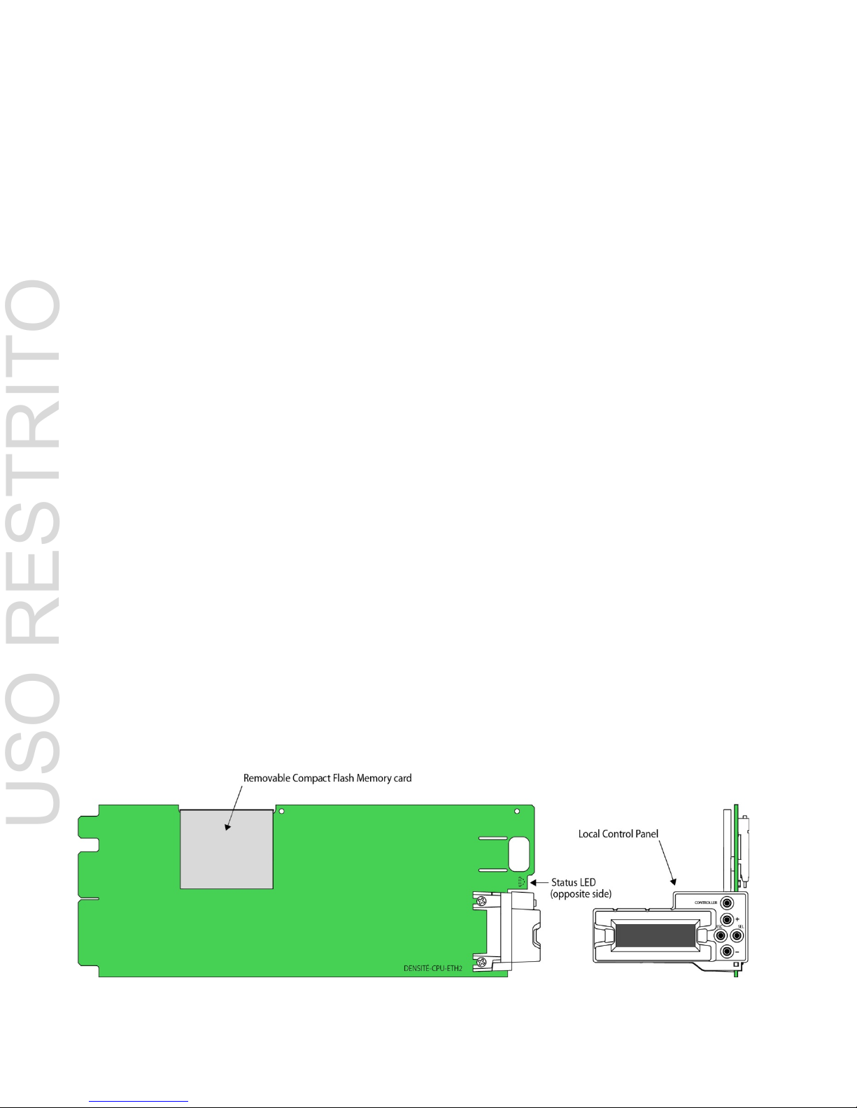
• Removable Compact Flash memory card for portable and quickly-recov erable device and frame configuration
• User-configurable GPI alarm port
• Features front display panel and push-buttons for local configuration of cards and frame
• Can be remotely configured via iControl
• Provides card and frame health monitoring and status reporting
• Provides extensive frame monitor in g:
o Ethernet port monitoring, with communication settings and overall bit rate
o detailed bitrate and communication throughput from individual cards
o self-monitoring with CPU load, memory usage
o Power Supply and GPI status reporting
• Individual Card parameter storage for easy card swapping
• Communication speeds of up to 100 Mbps via Ethernet ports
1.3 Card Layout
USO RESTRITO
Page 6
GUIDE TO INSTALLATION AND OPERATION
2 | CPU-ETH2
2 Operation
2.1 Overview
All of the cards installed in a DENSITÉ frame are internally connected to the frame’s controller card, which handles all
interaction between the cards and the outside world. The controller supports remote operation via its Ethernet ports,
and local operation using its integrated control panel.
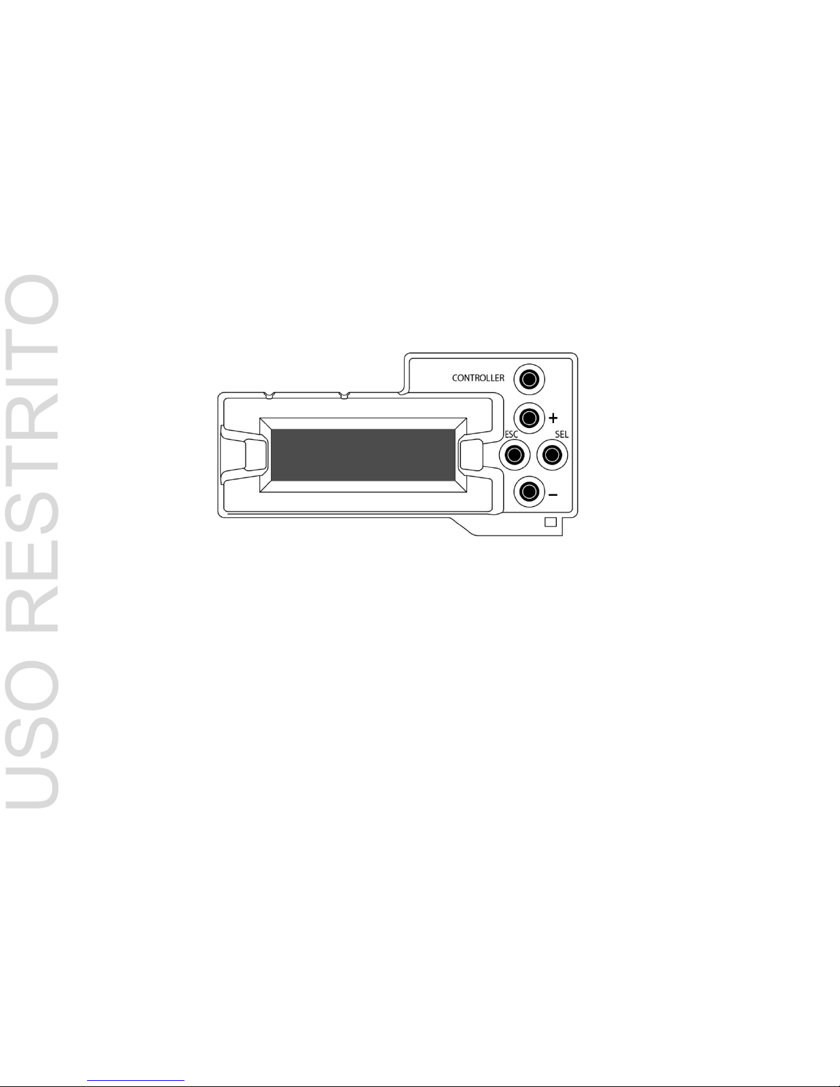
2.2 The Local Control Panel
The local control panel is fastened to the front of the CPU-ETH2 controller card, and when installed is located in the
front center of the frame, positioned in front of the power supplies. The panel consists of a display unit capable of
displaying two lines of text, each 16 characters in length, and five pushbuttons.
The panel is assigned to operate any card in the frame by pushing the SELECT button on the front edge of that card.
Pushing the CONTROLLER button on the control panel selects the Controller card itself. The STATUS LED on the
selected card flashes yellow.
The local control panel displays a menu that can be navigated using the four pushbuttons located beneath the display.
The method of navigating the menu and selecting and modifying parameters is common for all cards. For detailed
information about the menu for a specific card, see its manual. For detailed information about the menu for the
controller card itself, see page 16.
The functionality of the five pushbuttons is as follows:
[CONTROLLER] Selects the controller card for status monitoring and adjustment
[+] [–] Used for menu navigation and value modification
[SEL] Gives access to the next menu level. When a parameter value is shown, pushing this button once
enables modification of the value using the [+] and [–] buttons; a second push confirms the new
value
[ESC] Cancels the effect of parameter value changes that have not been confirmed; pushing [ESC]
causes the parameter to revert to its former value.
Pushing [ESC] moves the user back up to the previous menu level. At the main menu, [ESC] does
not exit the menu system. To exit, re-push the [SEL] button for the card being controlled.
If no controls are operated for 30 seconds, the controller reverts to its normal standby status, and the selected card’s
STATUS LED reverts to its normal operating mode. The parameter currently being edited will be saved.
USO RESTRITO
Page 7

GUIDE TO INSTALLATION AND OPERATION
CPU-ETH2 | 3
2.3 Sta tu s LED
The status monitor LED is located on the front card-edge of the controller module, and is visible through the front
access door of the DENSITÉ frame. This multi-color LED indicates module status by color, and by flashing/steady
illumination, according to the chart. The chart also indicates fault reporting for this card on the DENSITÉ frame’s serial
and GPI interfaces.
GPI
Report
COLOR (F=flashing)
G Y R FR
No errors
Power supply
failure
Fan failure
Internal error
: Factory default.
: LED color and reporting not user configurable
NOTE: A “Flashing Yellow” Status LED indicates one of the following:
• The CTRL button on the front panel has been pushed.
• The controller is displaying a spontaneous message – see the display for details.
• The controller is booting up, after a reset or power up. A status message is displayed. Once the boot process is
completed, the LED will go to steady green unless there are other errors per the above chart.
3 Pr e liminary Configuration
The first step in setting up a new Densité frame and its associated CPU-ETH2 controller to operate in your network is
to configure its IP address to fit into your network structure. This is most easily done by using the onboard menu and
local control panel. Proceed as follows:
1. Obtain the appropriate IP address, Network Mask and Gateway from your IT department, if necessary.
2. Power up the Densité frame.
3. Open the front door to the frame.
4. Push CONTROLLER on the local control panel located in the center of the frame (see section 2.2 on page 2)
5. Using the local control panel, scroll down the menu using the – key until the screen displays ETH1 OPTIONS
6. Push SEL and then – to move to the IP ADDRESS section
7. Enter the IP address, then scroll down to enter the Network Mask and Gateway values.
USO RESTRITO
Page 8
GUIDE TO INSTALLATION AND OPERATION
4 | CPU-ETH2
8. Push ESC until you are back at the main menu, and then push the CONTROLLER button again to exit the menu
system and save your changes.
Note that if you do not use the controller buttons for thirty seconds, the process will time out, so have your data ready
to enter when you start.
4 Local Cont rol Operation
Push the CONTROLLER button on the local control panel to assign that panel to operate the CPU-ETH2 controller.
Use the control panel buttons to navigate through the menu, as described in 2.2 above.
The menu is discussed and displayed beginning on page 16.
5 Remote Control Oper a t ion
This card supports remote operation through two rear-panel 10/100 Base-T ethernet ports, using Miranda’s iControl or
a third-party solution. The command set available for communicating with a DENSITÉ frame permits more complex
and comprehensive control, parameter storage, and field upgrading than is supported by the local control panel.
Miranda’s iControl solution gives access to the settings and adjustments for the CPU-ETH2 controller card in a
Densité frame, and also to these features for all cards installed in the frame. For that reason, the iControl interface is
used as the primary reference to describe the set-up and operation of the CPU-ETH2.
5.1 CPU-ETH2 Web Page
However, the CPU-ETH2 also serves a web page which provides an alternate means of configuring the card. The
web page does not give access to controls for other cards in the frame, however.
The web page is the only point of access for upgrading the CPU-ETH2 firmware – this function is not supported under
iControl, or via the local control panel.
See section on page for instructions on accessing the web page and upgrading the CPU-ETH2 firmware.
5.2 iControl Interface
The operation of the CPU-ETH2 card can be controlled using
Miranda’s iControl system. This manual describes the control
panels associated with the CPU-ETH2 and their use. Please
consult the iControl User’s Guide for information about setting
up and operating iControl.
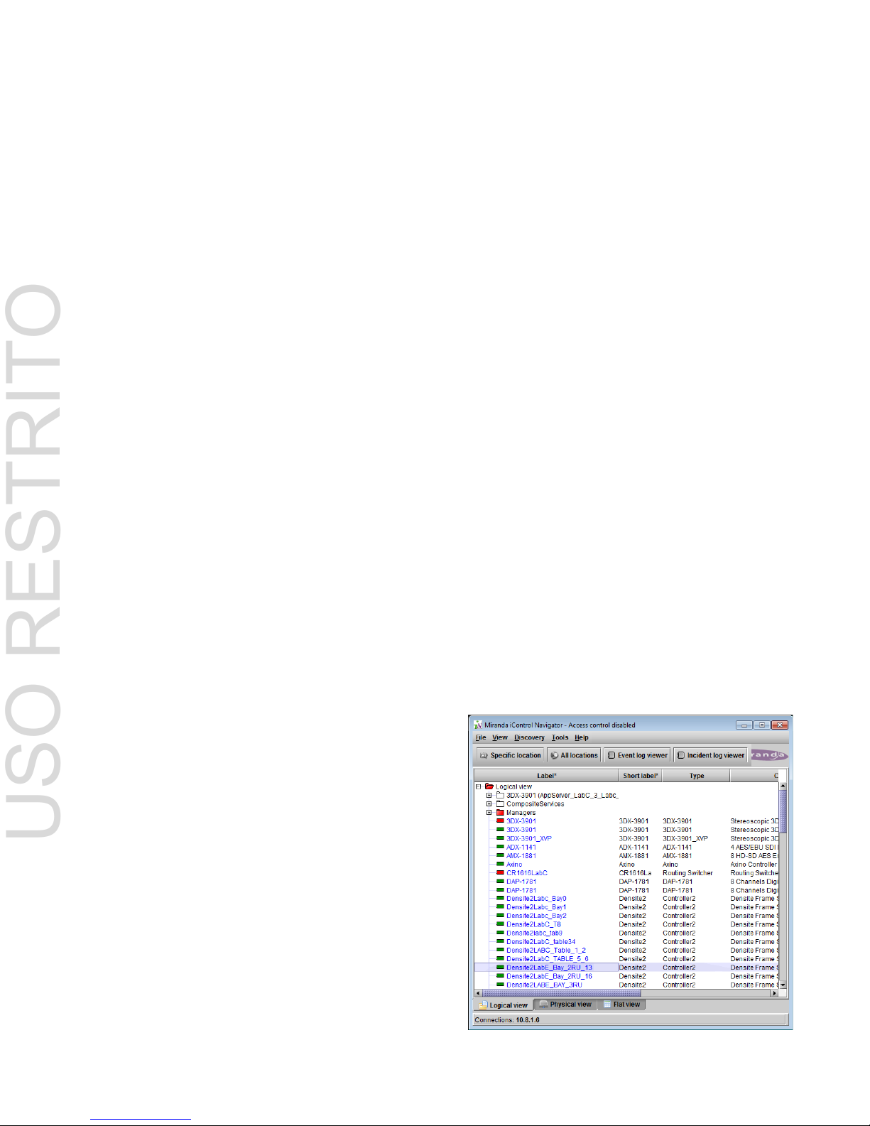
In iControl Navigator or iControl Websites, double-click on the
icon of the controller to open its control panel.
• CPU-ETH2 controllers are identified as Controller2 in the
Type column of the iControl Navigator window.
• For convenience, enter a descriptive Label in the Info
panel of the card, to make it easy to locate this specific
frame controller amongst those in the list. See page 5.
USO RESTRITO
Page 9

GUIDE TO INSTALLATION AND OPERATION
CPU-ETH2 | 5
5.3 Feature Management
This section introduces the operating features of the CPU-ETH2 controller, and describes how to access and control
them using:
• The iControl interface
• The local control panel and menu.
The following topics are covered:
Identification .............................................. see page 5
Status Monitoring ...................................... see page 6
Network Configuration .............................. see page 6
SNMP Functionalitysee page Error! Bookmark not defined.
Data restoration ...................................... see page 10
Factory Alignment ................................... see page 11
Time management .................................. see page 11
Alarms ..................................................... see page 12
Options ................................................... see page 14
5.3.1 Topic – Identification
The CPU-ETH2 controller is accessible on a network, and must
be identifiable in order to function in the iControl environment. The
identification data is entered in the iControl INFO control panel.
This panel also shows other data that is not user-adjustable.
You can enter the following information by clicking and typing in
the data box:
• Label: allows the user to define the label that appears
for this device when it appears in iControl
applications
• Short Label: allows the user to define the short-form label for
iControl (8 characters)
• Source ID: type a descriptive name for this CPU-ETH2
controller
• Comments: type any desired text
The remaining data boxes show manufacturing information about
this card.
Three buttons in the panel give access to other inform at ion.
• Details: Reports the Firmware version, service version, and panel version for this card
• Advanced: Shows the Miranda LongID for this card. The Miranda LongID is the address of this CPU-ETH2
controller in the iControl network.
• Remote System Administration. Opens the Joining Locators data box.
USO RESTRITO
Page 10

GUIDE TO INSTALLATION AND OPERATION
6 | CPU-ETH2
Using the menu
None of this data can be accessed or entered via the local control panel menu, except the Firmware version.
5.3.2 Topic – Status Monitoring
The CPU-ETH2 controller continuously monitors the condition
and status of the frame it is controlling and the cards installed in
the frame. This information can be viewed in the iControl
STATUS panel.
The information is grouped into four classes:
1. Frame status
Select the Frame tab to see a report on the status of the frame’s
CPU, fans and power supplies.
The CPU-ETH2 card can be installed in Densité 2 and Densité 3
frames (including Densité 3 mini and Densité 3+ FRI), and the
frame type is indicated here.
2. Network Status
Select the Network tab to see a report on the status of the two
Ethernet ports on the CPU-ETH2 card.
USO RESTRITO
Page 11

GUIDE TO INSTALLATION AND OPERATION
CPU-ETH2 | 7
3. Card Throughput
Select the Cards tab to see a chart of the current send (Tx) and
receive (Rx) data rates, and speed, for all cards installed in the
Densité frame.
For a more detailed report on the status of a specific card, open
that card’s control panel in iControl.
4. CPU-ETH2 Card Resource Usage.
Select the Advanced tab to view a report on the usage of the
card’s resources:
USO RESTRITO
Page 12

GUIDE TO INSTALLATION AND OPERATION
8 | CPU-ETH2
5.3.3 Topic – Network Configuration
The CPU-ETH2 controller ’s two Ether net por ts can be conf igur ed usin g the iControl interface, or through the cardfront menu. Open the NETWORK panel and select the ETH tab to configure them through iControl.
Enter the HOSTNAME in the box at the top.
Then configure the two ports individually.
Consult your IT department if necessary before configuring
the ports, to ensure that the Densi té co n troller is correctly
integrated into your local network
IP Address:
Subnet mask:
Gateway:
Enter the values supplied
by your network
administrator
The MAC (Media Access Control) address is reported in the data
box
• The MAC address is not user-configurable.
Redundancy (option)
The Ethernet Link Redundancy option is configured in this panel.
• Note that the option must be purchased and activated
before this feature becomes available. See page 14 for
details.
Mode: enable or disable the link redundancy function
Type: select one of the available bonding modes
• Round Robin
• Active Backup
About Channel Bonding (Ethernet Link Redundancy option)
Channel bonding is an arrangement in which two or more network interfaces on a host computer are combined
for redundancy or increased throughput.
• The Densité CPU-ETH2 Ethernet Link Redundancy option must be enabled to use Channel Bonding.
The Densité CPU-ETH2 supports two bonding modes:
Round-Robin: This mode provides load balancing, fault tolerance and increased throughput. Transmissions
are received and sent out sequentially on each bonded slave interface beginning with the first one available.
This mode requires that the remote equipment (host or switch) be configured to aggregate traffic over several
ports (Trunk, EtherChannel, etc.).
Active-Backup: This mode provides fault tolerance. Transmissions are received and sent out via the first
available bonded slave interface. The other bonded slave interface is only used if the active bonded slave
interface fails. This mode doesn't require any configuration of the remote equipment.
When Channel Bonding is enabled, the two Ethernet interface are seen as one. Therefore Eth 2 settings are
disabled and network settings are changed using Eth 1.
USO RESTRITO
Page 13

GUIDE TO INSTALLATION AND OPERATION
CPU-ETH2 | 9
Using the Menu
The local control panel menu can also be used to enter these values:
Hint: the first time you set up the CPU-ETH2 card, get the Network details from your IT manager and install them on
the card using the menu. The card will then be easy to find using iControl applications.
The data entry points are found in the menu under ETH1 OPTIONS and ETH2 OPTIONS. Note that the Hostname is
reported in the menu but cannot be changed from there.
5.3.4 Topic – SNMP functionality
The CPU-ETH2 card can function as an SNMP agent, sending
SNMP traps to designated targets. The SNMP agent can also be
polled to obtain the frame status.
Open the NETWORK panel and select the SNMP tab.
Click the Activate SNMP Agent box to activate this feature
Enter the IP addresses of up to three SNMP trap targets in the
boxes provided.
Using the Menu:
SNMP activation and the three target IP addresses can be
entered in the menu via the SNMP OPTIONS item.
USO RESTRITO
Page 14

GUIDE TO INSTALLATION AND OPERATION
10 | CPU-ETH2
5.3.5 Topic – Data Restoration
Many of the Densité-series cards that can be installed in the frame with the CPU-ETH2 controller are complex and
have a lot of data stored on-board related to their configuration and parameter values. The CPU-ETH2 controller
provides a backup of this data, which can be restored to the card when needed. This is valuable if the card is
inadvertently reconfigured, or is replaced after failure with a new card of the same type. Data restoration is managed
from the Restore Point iControl panel.
Open the Restore Point panel and view the Cards tab.
The tab show a list of the 20 slots available in the Densité frame,
with a checkbox, name, and status box for each.
• Click the checkbox to activate the Data Restore feature
for the card in that slot,
-or-
• Click the Select All box at the top to activate the feature
for all slots in the frame.
Click Save to controller at the bottom to copy all restorable data
from the cards in the selected slots into the memory on board the
CPU-ETH2 controller.
Click Load to cards to load the cards in the selected slots with
data from the controller’s memory.
Note that a data restore will only work if the card in the slot is the
same type as the card that was there when the data was saved.
Automatic restore
The CPU-ETH2 card can be set up to automatically update a
card when it is inserted in a slot previously occupied by a card of
the same type whose data was saved. Thus, a new card can be
configured automatically to replace the card that was removed,
saving a lot of time when cards are swapped.
Open the Config tab in the Restore Point panel.
Click the Restore Settings on Card box to enable the auto
restore function for all the cards in the frame.
Using the menu
Access the data restore function from the Restore Points menu
item
USO RESTRITO
Page 15

GUIDE TO INSTALLATION AND OPERATION
CPU-ETH2 | 11
5.3.6 Topic – Factory Alignment
There may be times when the CPU-ETH2 settings have been
adjusted and it is useful to restore them to a normalized
condition. The CPU-ETH2 controller maintains a “Factory
Default” alignment in its memory, to which it can be restored at
any time.
Note: Ethernet settings are not included in the Factory data set,
and are not changed when the Factory Default alignment is
installed.
Open the Factory iControl panel.
Click the Load Factory button to restore the card to the Factory
default alignment.
Using the menu
The factory default values can be loaded from the FACTORY
menu item.
The default values are shown underlined in the menu listing
beginning on page 16.
5.3.7 Topic – Time management.
The CPU-ETH2 controller is time-aware, and its internal clock can be updated via several mechanisms.
Open the iControl Time panel.
Time (UTC)
The data boxes in this section display the time and date currently
held in the card.
Enter new values in these boxes to change the current setting. If
an automatic update via NTP is not enabled, the clock will
continue to run using an on-board reference, but preci s ion is not
guaranteed.
NTP IP address
Click the Enab le NTP box to use an NTP (Network Time
Protocol) source. Enter up to three IP addresses of NTP servers.
The CPU-ETH2 card will use the first source of valid time it finds
in this list.
Using the menu
You can enter the current time and date, and activate the NTP
time sourcing through the TIME OPTIONS menu item.
USO RESTRITO
Page 16

GUIDE TO INSTALLATION AND OPERATION
12 | CPU-ETH2
5.3.8 Topic – Alarms
The CPU-ETH2 controller generates
alarms for the frame in which it is
installed when error conditions are
detected. The iControl Alarm
Configuration panel allows the alarm
reporting of the CPU-ETH2 to be
configured.
The panel opens in a new window
when the Alarm Config. but ton is
clicked, and can be resized if
needed.
The panel is organized in columns.
Status/Name
This contains an expandable tree listing all the alarms reported by this CPU-ET H 2 contr oller.
• Each alarm name includes an icon that shows its current status
The Overall alarm and GSM contribution columns contain pulldown lists that allow the level of contribution of each
individual alarm to the alarm named in the column heading to be set.
Click on the alarm icon to see the available levels; then click on one to select it
Overall Alarm
This column allows configuration of the contribution of each individual alarm to the Overall Alarm associated with this
card. The Overall Alarm is shown in the upper left corner of the iControl panel, and also appears at the bottom of the
Status/Name column.
GSM Contribution
This column allows configuration of the contribution of each individual alarm to the GSM Alarm Status associated with
this card. GSM is a dynamic register of all iControl system alarms, and is also an alarm provider for external
applications. The possible values for this contribution are related to the Overall alarm contribution:
• If the Overall alarm contribution is selected as Disabled, the GSM alarm contribution can be set to any available
value
• If the Overall alarm contribution is selected as any level other than disabled, the GSM contribution is forced to
follow the Overall Alarm.
USO RESTRITO
Page 17

GUIDE TO INSTALLATION AND OPERATION
CPU-ETH2 | 13
Levels associated with these alarms:
The pulldown lists may contain some or all of the following options:
The alarm makes no contribution (black icon)
The alarm is of minor importance (yellow icon)
The alarm is of major importance (orange icon)
The alarm is of critical importance (red icon)
The alarm exists but has no effect (used for text and composite alarms)
Shortcut: if you click in one of the Set All boxes beside a section heading, you will open a pulldown that lets you
assign a level to all alarms in that section of the column simultaneously.
.
Once the alarms are configured, you may accept the changes or discard them:
Log Events
iControl maintains a log of alarm events associated with the card. The log is useful for troubleshooting and identifying
event sequences. Click in the checkbox to enable logging of alarm events for each individual alarm.
At the bottom of the window are several other controls
Copy to other cards
Click this button to open a panel that allows the alarm
configuration set for this card to be copied into other CPU-ETH2
controllers in other frames.
• Select one or more destination controllers from the list in the
window by clicking in the checkboxes, or all of them by
clicking in the All checkbox
Get alarm keys
Click this button to open a save dialog where you can save a file
containing a list of all alarms on this controller and their current
values, along with an Alarm Key for each. The alarm keys are
useful for system integration and troubleshooting.
• The file is saved in .csv format
USO RESTRITO
Page 18

GUIDE TO INSTALLATION AND OPERATION
14 | CPU-ETH2
OK, Apply, Cancel
• OK accepts the settings and closes the window once the controller confirms that there are no errors.
• Apply accepts the settings, but leaves the window open
• Cancel closes the window without applying any changes, and leaves the previous settings intact.
Using the Menu
Access the Alarm Report menu item, and scroll through the list of available alarms, setting each to OFF or to report
through GPI.
5.3.9 Topic - Options
Only one option is available for the CPU-ETH2 controller.
The Ethernet Link Redundancy option uses channel bonding to
achieve redundancy or increased throughput. TheCPU-ETH2
offers two bonding modes – Round-Robin and Active-Backup.
Once this option is activated, the bonding mode can be
selected, and the option itself enabled or disabled, in the ETH
tab of the Network iControl panel – see page 8.
Page 8 also gives a more detailed description of the two
channel bonding modes.
USO RESTRITO
Page 19

GUIDE TO INSTALLATION AND OPERATION
CPU-ETH2 | 15
6 Local Controller Operation
Push the CTRL button on the local control panel to access the CPU-ETH2 card’s menu structure shown below. Here
is a summary of the top-level menu items and the content they access.
Status If there are faults, the second line of the display initially shows “Status”. It then cycles through a list
of the current faults, for example: FAN2 FAILURE or PS1 FAILURE.
Host name Reports the host name of the controller.
ETH1 Options Allows the user to enable/disable DHCP, and to set the IP address, network mask and gateway
URL for the ETH1 port.
ETH2 Options Allows the user to enable/disable DHCP, and to set the IP address, network mask and gateway
URL for the ETH2 port.
SNMP Options Enable/disable the SNMP agent, and manage IP addresses for SNMP traps.
Restore points Save the on-board data for all cards in the Densité frame, or for a designated card.
Time options Sets up the method by which the CPU-ETH2 controller obtains time information.
Alarm Report Allows the user to cycle through a list of alarms and choose whether each item will be reported on
the GPI port.
GPI Report Allows the GPI output to be enabled or disabled; disable removes any existing fault report
CTRL Version Returns the version number of the currently-installed firmware.
Factory Default Restores factory default settings for all parameters (but not ethernet settings).
Upgrade Perform a controller firmware upgrade.
CTRL Execution Reboot the controller card.
USO RESTRITO
Page 20

GUIDE TO INSTALLATION AND OPERATION
16 | CPU-ETH2
6.1 DENSITÉ CPU-ETH2 MENU
PS1 FAILURE
PS2 FAILURE
PS1 FAN FAILURE
PS2 FAN FAILURE
FAN1 FAILURE
FAN2 FAILURE
GPI ACTIVATED
INTERNAL FAILURE
CF CARD FAILURE
RAM FAILURE
FPGA LOAD FAIL
ETH1 FAILURE ETH1 DOWN, ETH1 UP <SPEED> <DUPLEX>
ETH2 FAILURE ETH2 DOWN, ETH2 UP <SPEED> <DUPLEX>
<HOST NAME>*
[ENABLE, DISABLE]
[ [0…255] . [0…255] . [0…255] . [0…255] ]
[ [0…255] . [0…255] . [0…255] . [0…255] ]
[ [0…255] . [0…255] . [0…255] . [0…255] ]
[ [0…FFF] [0…FFF] [0…FFF] ] *
[AUTONEGOTIATION, 100Base Tx-FD,
100base TX-HD, 10baseT-FD, 10baseT-HD]
(SAME AS FOR ETH1)
[ENABLE, DISABLE]
[ACTIVE-BACKUP, ROUND-ROBIN]
[ENABLE, DISABLE]
[ [0…255] . [0…255] . [0…255] . [0…255] ]
[ [0…255] . [0…255] . [0…255] . [0…255] ]
STATUS
ETH2 OPTIONS
GATEWAY
NETWORK MASK
SNMP TRAPS
DHCP
ETH1 OPTIONS
MAC ADDRESS
HOST NAME
SNMP AGENT
IP ADDRESS
SNMP OPTIONS
ADD IP ADDRESS
LIST IP ADDRESS
REMOVE ADDRESS
BONDING MODE
BONDING OPTION
CHANNEL BONDING
MII STATUS
USO RESTRITO
Page 21

GUIDE TO INSTALLATION AND OPERATION
CPU-ETH2 | 17
[ [0…255] . [0…255] . [0…255] . [0…255] ]
[ENABLE, DISABLE]
[ [1….20] ]
[ [1….20] ]
[KEEP, UPDATE]
[ENABLE, DISABLE]
[DAY, WEEK, MONTH]
[ [HH] : [MM] : [SS] ]
[ [DD] : [MMM] : [YY] ]
[ENABLE, DISABLE]
[ [0…255] . [0…255] . [0…255] . [0…255] ]
[ [0…255] . [0…255] . [0…255] . [0…255] ]
[ [0…255] . [0…255] . [0…255] . [0…255] ]
[EVERY [HH] HOUR]
[NONE, GPI]
[NONE, GPI]
[ENABLE, DISABLE]
[FIRMWARE V.XXX] *
[VERSION X.X.X] *
[LINK REDUN ON/OFF] *
[RESTORE]
Sets all parameters shown above to their underlined default values.
[REBOOT]
FACTORY DEFAULT
FAN FAILURE
PS FAILURE
ALARM REPORT
CTRL VERSION
* Values marked with an asterisk are displayed but cannot be modified through this menu.
LOAD A CARD
LOAD ALL CARDS
SAVE ALL CARDS
RESTORE POINTS
DEFAULT ACTION
SAVE A CARD
NTP SERVER
NTP CLIENT
TIME
TIME OPTIONS
NTP REFRESH
DATE
ADD IP ADDRESS
LIST IP ADDRESS
REMOVE ADDRESS
GPI REPORT
CTRL EXECUTION
AUTO SAVE
SAVE EVERY
WEB SERVER
BOOT-LOADER VER
OPTIONS
USO RESTRITO
Page 22

GUIDE TO INSTALLATION AND OPERATION
18 | CPU-ETH2
7 Upgra ding the CPU-ETH2
Upgrading the CPU-ETH2 firmware must be accomplished via a web page served by the controller, and accessed
through its ethernet port using a browser. Proceed as follows:
1. Obtain an upgrade file from Miranda Technologies.
The file you will receive from Miranda will be named 659-01P02-###.zip, where xxx is the firmware release
version number.
Unzip the file, and save the expanded file, which will be named 7659-0102-###.img.
This .img file is the file you will need to upgrade the CPU-ETH2 card in step 5 below..
2. Using a browser on your network, browse to the IP address of the CPU-ETH2 card.
You will have set this address in the preliminary section of the controller setup – see section 3 on page 3 of this
manual.
• If you are using iControl, double-click the controller in the iNavigator page, and select NETWORK | ETH
to see the IP address.
You will be asked for a username and password – the default values are:
• Username = admin
• Password = (leave blank)
The CPU-ETH2 web page will open in your browser.
USO RESTRITO
Page 23

GUIDE TO INSTALLATION AND OPERATION
CPU-ETH2 | 19
3. In the left-side menu, select Tools | Upgrade Firmware.
The current firmware version is shown at the top of the window
4. Click Browse.
5. In the Choose File to Upload window,
browse to the upgrade file you obtained
in Step 1 (named 7659-0102-###.img),
select it and click Open.
USO RESTRITO
Page 24

GUIDE TO INSTALLATION AND OPERATION
20 | CPU-ETH2
In the Tools | Upgrade Densité Controller window, the new upgrade version will be shown at the top of the
page, and the Upgrade button will be enabled.
6. Click Upgrade.
The window will show the status of the upgrade process.
The CPU-ETH2 card will reboot once the upgrade is complete.
7. Click Log Out at the bottom left of the window to exit the CPU-ETH2 web page.
USO RESTRITO
 Loading...