

Page 1

imaging Series
NTSC/PAL to 4:2:2
ASD-231i
Guide to Installation and Operation
M212-0900-101
Copyright 2002 Miranda Technologies Inc.
Specifications may be subject to change.
Printed in Canada
August 2002
Adaptive Decoder
with TBC
Miranda
3499 Douglas-Floreani, St-Laurent
Technologies inc.
(Québec) Canada, H4S 2C6
231i
-
ASD
Page 2

WARRANTY POLICIES
Warranty Statement
Miranda Technologies Inc. warrants that the equipment it manufactures shall be free from defects in material and
workmanship for a period of two (2) years from the date of shipment from the factory. If equipment fails due to such defects,
Miranda Technologies Inc. will, at its option, repair or provide a replacement for the defective part or product. Equipment that
fails after the warranty period, has been operated or installed in a manner other than that specified by Miranda, or has been
subjected to abuse or modification, will be repaired for time and material charges at the Buyer’s expense.
All out-of-warranty repairs are warranted for a period of ninety (90) days from the date of shipment from the factory.
Miranda Technologies Inc. makes no other warranties, expressed or implied, of merchantability, fitness for a particular
purpose or otherwise. Miranda’s liability for any cause, including breach of contract, breach of warranty, or negligence, with
respect to products sold by it, is limited to repair or replacement by Miranda, at its sole discretion. In no event shall Miranda
Technologies Inc. be liable for any incidental or consequential damages, including loss of profits.
Effective January 1, 2002
Warranty Exchange Policies
Miranda Technologies Inc. warrants that the equipment it manufactures shall be free from defects in materials and
workmanship for a period of two (2) years from the date of shipment from the factory. If equipment fails due to such defects,
Miranda will provide repair of the failed unit under the terms of the Miranda warranty.
If the equipment has been proven to be defective on arrival, Miranda will ship a new product in exchange, usually within 36
hours of factory notification.
If the equipment to be repaired is essential and the customer so requests, Miranda will, at its option, provide a service
replacement or loaner part or product, usually within 36 hours of factory notification, weekends and holidays excluded.
All warranty exchange or loaner parts or products shall be shipped to the Buyer with a packing list clearly describing the
items and stating the date of shipment. Repaired parts or products will be shipped to the Buyer with a similar packing list. In
the case of exchange, the defective products or parts must be returned to Miranda within fifteen (15) days from receipt by
the customer of the exchange product. In the case of a loaner, the loaned products or parts must be returned to Miranda
within fifteen (15) days from receipt by the customer of the repaired equipment.
If the equipment is not returned within fifteen (15) days, as described for either exchanges or loans, A Rental Invoice will be
generated. Rental terms will be fifteen (15) percent of the current list price of the products or parts per month or a fraction
thereof. Before returning the equipment to Miranda Technologies Inc., for any reason, the Buyer must first obtain a Return
Authorization Number from Miranda Technologies Inc. Miranda Technologies Inc will pay freight and insurance charges for
the delivery of the loaner or exchange products or parts. Freight and insurance charges for the return of the defective
product or part will also be paid by Miranda Technologies.
Out-Of-Warranty Repair Policy
Miranda will repair equipment which is out of Warranty. The current pricing structure for this service is available from the
Miranda web site at
repairs are warranted for a period of 90 days from the date of shipment from the factory. Before returning the equipment to
Miranda Technologies Inc., for any reason, the Buyer must first obtain a Return Authorization Number from Miranda
Technologies Inc. In the case of a product deemed by Miranda to be beyond repair, the customer must purchase a new
product at current retail prices.
The Buyer will pay freight and insurance charges for the return of the defective product or part to the manufacturer for repair.
Miranda
Technologies will pay freight and insurance charges for the return of the repaired product or part to the Buyer.
Out-Of Warranty Equipment Updates and Spare Parts Policy
Miranda Technologies’ current pricing structure for out-of-warranty equipment updates, or the sale of spare parts, is
available from Miranda Technical Support Services at (514) 333-1772.
www.miranda.com
or from Miranda Technical Support Services at (514) 333-1772. All out-of-warranty
i
Page 3

SAFETY COMPLIANCE
This equipment complies with:
- CSA C22.2 No. 950 / Safety of Information Technology equipment.
- UL No. 1950 / Safety of Information Technology equipment.
WARNING
An appropriately listed/certified mains supply power cord must be used for the connection of the
equipment to the mains voltage either 120V or 240V.
CAUTION
These servicing instructions are for use by qualified service personnel only. To reduce the risk of electric
shock, do not perform any servicing other than that contained in the operating instructions unless you are
qualified to do so. Refer all servicing to qualified service personnel.
- EN60950: 1992 (incorporating A1, A2, A3, A4 and A11)/European Standard - Safety of Information
Technology equipment.
Electromagnetic Compatibility
- This equipment has been tested for verification of compliance with FCC Part 15, Subpart B, class A
requirements for Digital Devices.
- This equipment complies with the requirements of EN55022 Class A, Electromagnetic Emissions, En
61000-3-2, Disturbance in Supply Systems and EN55025, Electromagnetic Immunity.
How to contact us:
Head Office Miranda Europe Miranda Asia
Miranda Technologies Inc. 222, 226 Rue De Rosny Mita Nexus Bldg. 2F
3499 Douglas-B.-Floreani 93100 Montreuil 1-3-33 Mita, Minato-Ku
St. Laurent (Montreal), Que. H4S 1Y6 France Tokyo, Japan 108-0073
Canada
Tel +1 (514) 333-1772 +33 1 55 86 87 88 +81 3 5730 2988
Fax +1 (514) 333-6914 +33 1 55 86 00 29 +81 3 5730 2973
Toll free: 1-800-224-9828
www.miranda.com
ii
Page 4

CONTENTS
page
1 ASD-231i NTSC/PAL to 4:2:2 Adaptive Decoder with TBC........ 1
1.1 Introduction.................................................................................................. 1
1.2 Features....................................................................................................... 1
2 Installation............................................................…..................... 3
2.1 Unpacking................................................................................................... 3
2.2 ASD-231i Mechanical Installation................................................................ 3
2.2.1 imaging Quartet Series Frames..................................................... 3
2.2.2 imaging Symphonie Frame……………........................................... 3
2.2.3 imaging Solo Frame........................................................................ 3
2.3 Rear Panel Label......................................................................................... 4
2.3.1 imaging Quartet Series/Solo Frames……...............................…… 4
2.3.2 imaging Symphonie Frame………………..........................……….. 5
2.4 ASD-231i Electrical Installation................................................................... 6
3 Operation ..................................................................................... 9
3.1 ASD-231i User Interface.............................................................................. 9
3.2 Menu Introduction…………………………...........................………………… 9
3.3 Input Status Monitoring................................................................................ 12
3.4 Source Type Selection................................................................................. 12
3.5 Input Format Selection................................................................................ 12
3.6 Decoding Filter............................................................................................ 13
3.7 Timing .………………………………………..………….........................…… 13
3.7.1 Vertical Timing……………………..…………..........................……. 14
3.7.2 Horizontal Timing………………………………….........................… 14
3.8 Gain .………………………………………………..…….......................….. 14
3.8.1 Brightness………………………………...........................……..…… 14
3.8.2 Saturation………………………………..........................…………… 15
3.8.3 Overall Gain……………………………..........................…………… 15
3.9 Setup ................................................…................................................... 16
3.10 Hue ....................................................................................................... 16
3.11 Freeze Selection......................................................................................... 16
3.12 VANC Selection........................................................................................... 17
3.13 Closed Captioning Selection........................................................................ 18
3.14 True PAL Selection…………………………………..........................……….. 18
3.15 Factory Reset...…........................................................................................ 18
3.16 Color Bar Generator.................................................................................... 19
4 Stored Configurations.................................................................. 21
5 Specifications................................................................................ 23
i
Page 5

1 ASD-231i NTSC/PAL to 4:2:2 Adaptive Decoder with TBC
L
1.1 Introduction
The ASD-231i is a multi-standard, fully digital, 12-bit decoder with 3D and 2D adaptive decoding
capabilities allowing optimal picture quality with virtually no cross-color or cross-luma artifacts. A
built-in Time-Base Corrector (TBC) supports unstable (VHS) inputs. The TBC mode offers an
auto decoding filter selection which automatically switches between comb and bandsplit filtering
on the luminance path only.
The ASD-231i offers the possibility of connecting a reference input for complete studio
integration; it synchronizes serial 4:2:2 video to a local reference input. If no external reference is
detected, the ASD-231i locks on to the composite input.
If the input signal degrades or disappears, the ASD-231i can be set to freeze on the last errorfree field, switch to black, or disable the output 4:2:2 signals.
For those audio users requiring video delay tracking, a video processing delay signal provides
the ASD-231i input-output delay at all times.
The ASD-231i, with its built-in frame synchronizer and Automatic Gain Control supports stable,
unstable, and satellite inputs. All four 4:2:2 serial digital video signals respect the SMPTE 259MC standard. Also, the serial digital video outputs carry EDH data according to the SMPTE RP165
standard. Additionnally, the ASD-231i has a built-in color bars test signal.
The ASD-231i is a member of the imaging family of digital video modules and therefore requires
the imaging Quartet, imaging Symphonie, or imaging Solo frame for mounting and power.
Figure 1.1 ASD-231i Block Diagram
COMPOSITE
IN
REF IN
Genlock
12-Bit
ADC
Genlock
Frame
Sync/
Delay
Adaptive
TBC
Adaptive
Decoder
EDH
Microcontroller
1
2
4:2:2 OUT
3
4
DELAY
REMOTE CONTRO
1.2 Features
• NTSC, PAL, PAL-M, PAL-N, and SECAM composite inputs supported with passive loop-through
• Automatic or forced detection of composite input
• Analog reference input supported for complete studio timing
• Unstable (VCR) sources supported
1
Page 6

• 4 serial 4:2:2 outputs conforming to the SMPTE 259M-C standard
• Built-in frame synchronizer
• Built-in Automatic Gain Control (AGC)
• Adaptive Time-Base Corrector: automatic selection of 2D comb or bandsplit filtering on Y channel
• 2X oversampling
• 3D adaptive decoding
• True PAL decoding
• Video processing delay signal
• EDH insertion
• Built-in test signal
2
Page 7

2 Installation
2.1 Unpacking
Make sure the following items have been shipped with your ASD-231i. If any of the following
items are missing, contact your distributor or Miranda Technologies Inc.
• ASD-231i NTSC/PAL/SECAM to 4:2:2 Adaptive Decoder with TBC
• ASD-231i rear panel labels
• This manual
2.2 ASD-231i Mechanical Installation
The ASD-231i must be mounted within Quartet, Quartet-C, Quartet-M, Quartet-M-A75, QuartetM-A110, Symphonie (using Symphonie-R-M rear module), or Solo imaging frames in order to
provide power to the module. This section describes how to install the ASD-231i in any of these
frames. It is not necessary to switch off the power from these frames when installing or removing
the ASD-231i.
2.2.1 imaging Quartet Series Frames
To install this module into Quartet, Quartet-C, Quartet-M, Quartet-M-A75 or Quartet-M-A110
follow these steps. For a closer look at module installation and removal, refer to the frame's
Guide to Installation and Operation.
1. Remove the frame's front panel by rotating the thumb screws counter-clockwise. Pull on the
handles.
2. Select an empty slot.
3. Carefully place the ASD-231i between a set of module guides and gently push the module
towards the rear of the frame until the module's edge connector is secured to the backplane.
Pull lightly on the module verifying that it does not move.
4. Replace the frame's front panel. Make sure to rotate the thumb screws clockwise in order to
secure it to the chassis.
2.2.2 imaging Symphonie Frame
To install this module into Symphonie follow these steps. For a closer look at module installation
and removal, refer to the frame's Guide to Installation and Operation.
1. Remove the front panel door by pulling on the door handles and gently lowering it.
2. Select an empty compartment.
3. Carefully place the module between the module guides and slowly push the module towards
the rear of the frame until the module's edge connector is secured to its rear module. A light
pressure to mate the connectors may be required. Pull lightly on the module verifying that it
does not move.
4. Replace the front panel door.
2.2.3 imaging Solo Frame
To install this module into Solo follow these steps. For a closer look at module installation and
removal, refer to the frame's Guide to Installation and Operation.
3
Page 8
1. In order to remove the frame's front panel, gently pull on it.
2. Carefully place the ASD-231i between the module guides and gently push the module
towards the rear of the frame until the module's edge connector is secured to the backplane.
Pull lightly on the module verifying that it does not move.
3. Replace the frame's front panel.
2.3 Rear Panel Label
Connector labels have been shipped with the ASD-231i. These labels are to be installed on the
frames’ rear panel in order to identify the module's external connectors.
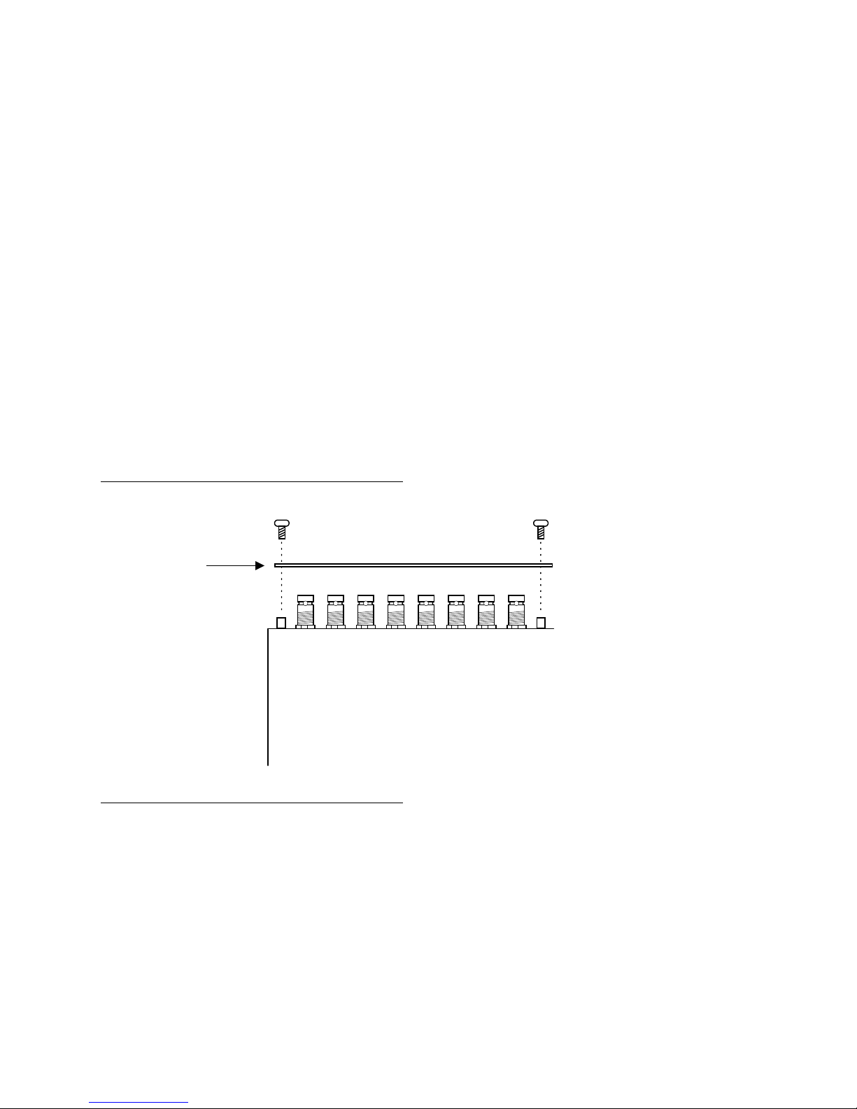
2.3.1 imaging Quartet Series/Solo Frames
To install the Quartet/Quartet-C/Quartet-M/Quartet-M-A75/Quartet-M-A110/Solo label, follow
these steps while referring to Figure 2.1.
1. Remove the screws associated with the ASD-231i connectors.
2. Carefully apply the label to the connectors.
3. Replace the screws making sure not to damage the label.
Figure 2.1 Quartet/Solo rear panel label installation
ASD-231i label
imaging Quartet, Quartet-C, Quartet-M,
Quartet-M-A75, Quartet-M-A110,
imaging
or
Solo
(top view)
4
Page 9

2.3.2 imaging Symphonie Frame
To install the Symphonie label, follow these steps while referring to Figure 2.2.
1. On Symphonie’s rear panel, locate the appropriate connectors.
2. Remove the rear label mounting screws from the rear module.
3. Carefully apply the label to the connectors making sure the label’s text is read from top to
bottom.
4. Replace the screws making sure not to damage the label.
Figure 2.2 Symphonie rear panel label installation
5
Page 10

2.4 ASD-231i Electrical Installation
When connecting the ASD-231i to external equipment, make sure that all serial digital
connections are point-to-point. For instance, there must be a point-to-point connection between
a 4:2:2 OUT BNC and target equipment. If a T-connector is used to connect other equipment,
the maximum specified cable length is no longer valid. Make sure the output cables have
maximum lengths of 250 m (850') each.
COMPOSITE IN - composite video with passive loop-through
Connect a NTSC, PAL, PAL-M, PAL-N, or SECAM composite video source to COMPOSITE
IN. Refer to Figure 2.2. NTSC signals must conform to the SMPTE 170M standard; PAL
(625/50), PAL-M (525/60), PAL-N (625/50), and SECAM (625/50) signals must conform to
the ITU (CCIR) 624-4 standard.
If the loop-through output is not used, terminate it with a 75 ohm termination.
REF IN - reference input with passive loop through
If you wish to reference the ASD-231i to the rest of your facilities, connect a studio reference
signal to the BNC labeled REF IN. The ASD-231i accepts SMPTE 170M/PAL ITU 624-4 or 2
Vpp/4 Vpp composite sync reference signals. Refer to Figure 2.2.
When using the Quartet, Quartet-C, Solo or Symphonie-R-C, the ASD-231i provides a loop
through output of the studio reference signal. Make sure to terminate this output with a 75
ohms terminator when it is not being used.
A valid analog composite reference signal will turn on the REF indicator located on the
module’s front end. The reference signal must be NTSC for 60 Hz sources (NTSC and PALM) and PAL for 50 Hz sources (PAL, PAL-N, and SECAM). If there exists a line format
mismatch between the reference input and the composite input, the REF indicator flashes.
4:2:2 OUT 1, 2, 3 and 4 - serial digital video outputs
The ASD-231i provides 4 video output BNCs. These BNCs, labeled 4:2:2 OUT 1, 2, 3 and 4,
provide the decoded video signal conforming to the SMPTE 259M-C standard.
Delay – video processing delay signal
When using a Quartet-M, -M-A75, -M-A110 or Symphonie-R-M, the ASD-231i provides a
video processing delay signal through an RJ-45 connector using RS-422A transport
standard. This signal may be used by an audio processor to avoid lip sync problems.
Connector pinout is detailed on Figure 2.3.
6
Page 11

Figure 2.2 ASD-231i electrical installation
Composite
loop through output
ASD-231i NTSC/PAL TO 4:2:2 DECODER W ITH TBC
123 4
REF IN
Studio reference
or black input
loop through output
COMPOSITE IN
Analog composite input
(NTSC, PAL, PAL-M,
PAL-N, SECAM)
ASD-231i NTSC/PAL TO 4:2:2 DECODER W ITH TBC
REF IN
Reference
COMPOSITE IN
Composite
loop through output
4:2:2 OUT
SMPTE 259M-C
4:2:2 video outputs
Figure 2.3 Video processing delay connector pinout
Pin
1NC
2NC
3GND
4DELAY (+)
RJ-45 Connector
Pin Location
5DELAY (-)
6NC
7NC
8NC
9NC
10 NC
DELAY
Video processing
delay output
1234
4:2:2 OUT
Quartet-M
Quartet-M-A75
Quartet-M-A110
Symphonie-R-M
Quartet
Quartet-C
Solo
Symphonie-R-C
7
Page 12

8
Page 13

3 Operation
3.1 ASD-231i User Interface
Figure 3.1 illustrates the ASD-231i's user interface situated at the front end of the module. The
interface components include the following:
• 4-character dot matrix display and 4 push-buttons for menu access
• Input status monitoring: reference and composite source signals
• Source Type selection
• Test pattern selection
Figure 3.1 ASD-221i user interface
IN
REF
ERR
ESC
ASD-231i NTSC/PAL TO 4:2:2 DECODER WITH TBC
3.2 Menu Introduction
Most ASD-231i parameters are accessed and changed via an easy-to-use menu. The flow chart
of Figure 3.2 outlines the entire ASD-231i menu path. The menu consists of 11 major functions:
format, filter, timing, gain, setup, hue, freeze mode, vertical ancillary mode, CC, true PAL filtering,
and factory reset. Each menu is described throughout this section. The following items should
be remembered when accessing the menu.
Normal Mode
When the menu is not being accessed we refer to this as normal mode. When in normal mode,
the current format loaded by the ASD-231i is displayed and the display is dimmed.
Navigating Through the Menu
The front panel push-buttons are used to navigate the menu of Figure 3.2. The following
describes the function of each push-button when navigating through the menu.
+: Press + to move down in the menu or to increase the parameter value. For example,
if you are currently at GAIN-BRI, pressing + will scroll downwards through the
STUDIO SATELLITE
SOURCE TYPE
VCR
+-
TEST
SELECT
9
Page 14

selections SAT and ALL. Depressing + during an adjustment will increase the
parameter value at a faster rate.
-: Press - to move up in the menu or to decrease the parameter value. For example, if
you are currently at TIMG-HOR, pressing - will scroll upwards to the selection VERT.
Depressing - during an adjustment will decrease the parameter value at a faster rate.
SELECT: Changes to a menu parameter are stored immediately to non-volatile memory. For
example, after the desired setup has been set, press SELECT. The menu returns to
STUP and the new setup value is stored for the current format.
ESC: If ESC is pressed after making changes to a parameter, the parameter is reset to the
value it had prior to the change. For example, after changing the brightness, press
ESC. The menu is returned to BRI and the previous brightness gain is reloaded.
Automatic Exit From Menu After 1-Minute Interval
If the menu is currently being accessed and no push-button has been pressed for 1 minute, the
ASD-231i automatically exits from the menu thereby returning to normal mode. Also, changes
made to the current parameter will be stored.
10
Page 15

Figure 3.2 ASD-231i menu structure
format S E
FRMT
S E [AUTO
,NTSC,PAL,PALM,PALN,SECM,BW]
+
-
E
FLTR
S E [A-3D,A-2D,3D,2D,SPLT] (Studio/Satellite)
+ [SPLT,AUTO] (VCR)
(No FLTR selection during SECAM)
-
E
TIMG
S E
VERT
S E [0,…,524] (step=1, unit=LINE) (NTSC/PAL-M)
+ + [0,…,624] (step=1, unit=LINE) (PAL/PAL-N/SECAM)
-
E
S E [0,…,63.5] (step=0.04, unit=us) (NTSC/PAL-M)
HOR
[0,…,64.0] (step=0.04, unit=us) (PAL/PAL-N/SECAM)
-
E
GAIN
S E
S E [-500,…,0,…,+500] (step=1)
BRI
+ +
-
E
S E [-500,…,0,…,+500] (step=1)
SAT
+
-
E
S E [VAR+,NOM,VAR-,VAR]
ALL
-
E
STUP
S E [-15,…,7.5,…,15.0] (step=0.20, unit=IRE) (NTSC)
+ [-105,…,0,…,105] (step=1.25, unit=mV) (PAL-M)
[-107,…,0,…,107] (step=1.28, unit=mV) (PAL/PAL-N/SECAM)
-
E
S E [-180,…,0,…,180] (step=0.25, unit=DEG) (NTSC/Studio, NTSC/Satellite)
HUE
+ [-180,…,0,…,180] (step=1.50, unit=DEG) (NTSC/VCR only)
-
E
FRZE
S E [FLD,BLAK,KILL,OFF] (Not accessible during Studio with no ref.)
+
-
E
VANC
S E
PROC
S E [BLNK,DECD,PASS]
+ +
-
E
STUP
S E [OFF,ON] (NTSC/PAL-M only)
-
E
S E [OFF,ON] (NTSC/PAL-M only)
CC
+
-
E
TPAL
S E [OFF,ON] (PAL/PAL-M/PAL-N only)
+
-
E
FACT
S E
S S=Select
NO
+ E=Escape
- Underline indicates default value
E
YES
S
11
Page 16

3.3 Input Status Monitoring
REF
The REF LED turns on to indicate a valid composite signal has been detected on the REF IN
BNC. It will remain off if no reference signal is installed. If there exists a line format mismatch
between the reference input and the composite input, the REF LED flashes. To avoid this
situation, make sure both the reference and source signals are 525 (60Hz) lines or 625 (50 Hz)
lines.
IN ERR
The IN ERR (error) LED will turn on if no composite input signal is installed. Also, if a standard is
forced, for example, NTSC and the input signal detected is other than a NTSC signal, the IN ERR
LED will indicate an error. Make sure the source signal is properly connected to COMPOSITE IN
and verify for any source equipment errors. It is highly recommended to enable black & white
input detection when working with monochrome signals. Refer to section 3.5, Input Format
Detection.
3.4 Source Type Selection
The ASD-231i accepts three different types of sources: STUDIO, SATELLITE and VCR.
Select STUDIO sosurce type when using high quality sources, SATELLITE for satellite sources,
and VCR for unstable sources.
Changes to the input modes can only be made when in normal mode. Therefore, make sure you
have left the menu. Press the DOWN(-) push-button to scan through the available selections.
The selected source type turns on the appropriate LED.
N.B.: There is no STUDIO option available during SECAM operation.
3.5 Input Format Detection
The ASD-231i supports two modes of format detection: automatic input format detection and
forced input format selection.
Automatic Format Detection
During this mode of detection, the ASD-231i detects the type of input and automatically switches
to that format by loading the decoder with the format’s parameters. To enable automatic input
detection follow these steps:
1. Press SELECT to enter the menu. FRMT is displayed.
2. Press SELECT to enter the FRMT menu. The current format is displayed.
3. To set automatic detection, press the UP(+) or DOWN(-) push-button until AUTO is
displayed.
4. Press SELECT to store automatic input detection. FRMT is displayed.
5. To enable automatic input detection and return to normal mode, press ESCAPE.
NOTE: During automatic input detection, if the input signal changes while you are
attempting to change the value of a menu function, the ASD-231i exits from the menu,
returns to normal and attempts to locate the correct format. However, this feature is
disabled only when the FRMT menu is being accessed.
12
Page 17

Forced Input Format Selection
This mode allows you to select one of the input formats. During this mode of operation, the ASD231i remains configured with the format selected at all times regardless of the input signal’s
format. If the input signal’s format is other than that selected, the IN LED will turn on. This
feature is handy when you are certain that the input format will not change. To select the forced
input for forced input detection, follow these steps:
1. Press SELECT to enter the menu. FRMT is displayed.
2. Press SELECT to enter the FRMT menu. The current format is displayed.
3. To force an input format, use the UP(+) or DOWN(-) push-button to select between NTSC,
PAL, PALM (PAL-M), PALN (PAL-N), SECM (SECAM), and BW (monochrome).
4. Press SELECT to store the new forced input selection. FRMT is displayed.
5. To return to normal mode, press ESCAPE.
Monochrome Input Signal
When working with monochrome input signals, set the FRMT menu to BW to accept a black and
white input. Selecting BW forces the ASD-231i to disable decoding of the input signal. During
BW mode, automatic detection is made between 525- and 625-line formats. Detecting a 525-line
format signal will load the NTSC format and a 625-line format will load the PAL format.
3.6 Decoding Filter
The ASD-231i provides the 5 types of decoding filters which are listed in Table 3.1. The selection
of a decoding filter will depend highly on the nature of the input composite signal. For example,
choosing between A-3D and A-2D will depend highly on the content of your source. Most
artifacts will disappear with A-3D but a ghosting effect may appear with moving images. On the
other hand, A-2D may be more adept with fast moving images. The best way to decide which
decoding filter to use is to try out each one and compare their performances with the actual
source.
Table 3.1 Available decoding filters and recommended usage
Decoder Application
A-3D Static images requiring optimum performances (adaptive)
A-2D Fast moving images requiring optimum performances (adaptive)
3-D Static images (non-adaptive)
2D Fast moving images (non-adaptive)
SPLT Lower quality source
AUTO Bandsplit filter for unstable VCR signals
Adaptive luma comb decoding for stable VCR signals
N.B.: There is no filter selection available during SECAM operation.
3.7 Timing
When the ASD-231i is set to STUDIO source type and there is no reference signal installed, it
operates in Frame Delay/Frame Buffer mode: the timing adjustment sets the processing delay
between the input and output signals. Note that when operating in Frame Delay/Frame Buffer
mode, the minimum vertical timing adjustment value is fixed by the number of processing steps
selected (see table 3.2 for details) . However, when a reference signal is installed, the ASD-231i
13
Page 18

is in Frame Synchronizer mode: the timing adjustment sets the processing delay between the
reference and output signals.
3.7.1 Vertical Timing
The vertical timing adjustment is made in increments of 1 video line up to 524 lines in NTSC and
PAL-M and 624 lines in PAL, PAL-N, and SECAM. Follow these steps in order to adjust vertical
timing:
1. Press SELECT to enter the menu. FRMT is displayed.
2. Press the DOWN(-) push-button until TIMG is displayed.
3. Press SELECT to enable the phase menu. VERT is displayed.
4. Press SELECT to enable the vertical timing menu. The current timing delay in video lines is
displayed.
5. Press UP(+) to increase the timing delay and press DOWN(-) to decrease the timing delay.
Press UP(+) and DOWN(-) simultaneously to set the timing to 0 lines.
6. Press SELECT to store the new vertical timing for the current format. VERT is displayed.
7. Press ESCAPE to return to TIMG.
8. To return to normal mode, press ESCAPE.
Note: Vertical timing is not available when using SATELLITE or VCR source types and
when no reference signal is detected.
When operating in Frame Buffer/Frame Delay mode (Studio source type w/o
reference signal), the minimum vertical timing adjustment value changes with the
number of processing steps selected. Table 3.2 shows the minimum values for
different processing selections:
Table 3.2 Minimum Vertical Timing Adjustment for Decoding Filter and TPAL selection (see section 3.14
for details on TPAL Selection)
Decoding Filter TPAL Minimum Vertical Timing
Adjustment Value
A-3D / 3D OFF 1
A-2D / 2D OFF 2
SPLT OFF 2
AUTO (VCR) OFF 2
A-3D / 3D ON 2
A-2D / 2D ON 3
SPLT ON 3
AUTO (VCR) ON 3
3.7.2 Horizontal Timing
The horizontal timing adjustment is made in increments of 1/2 pixels up to a range of one video
line (63.5 us in NTSC and PAL-M and 64.0 us in PAL,PAL-N, and SECAM). Follow these steps
in order to adjust horizontal timing:
1. Press SELECT to enter the menu. FRMT is displayed.
2. Press the DOWN(-) push-button until TIMG is displayed.
3. Press SELECT to enable the phase menu. VERT is displayed.
4. Press UP(+) or DOWN(-) to display HOR.
14
Page 19

5. Press SELECT to enable the horizontal timing menu. The current timing delay in us is
6. Press UP(+) to increase the timing delay and press DOWN(-) to decrease the timing delay.
7. Press SELECT to store the new horizontal timing for the current format. HOR is displayed.
8. Press ESCAPE to return to TIMG.
9. To return to normal mode, press ESCAPE.
Note: Vertical timing is not available when using SATELLITE or VCR source types and
3.8 Gain
The brightness (luminance) and saturation (chrominance) gains can be controlled independently
or simultaneously, on a range of –500 to +500 by steps of 1 unit.
3.8.1 Brightness
Follow these steps in order to set the brightness gain level:
1. Press SELECT to enter the menu. FRMT is displayed.
2. Press the DOWN(-) push-button until GAIN is displayed.
3. Press SELECT to enable the gain menu. BRI is displayed.
4. Press SELECT to enable the brightness gain menu. The current gain level is displayed.
5. Use UP(+) or DOWN(-) to set the required brightness gain level. For a quicker response,
6. Press SELECT to store the new gain level for the current format. BRI is displayed.
7. Press ESCAPE to return to GAIN.
8. To return to normal mode, press ESCAPE.
3.8.2 Saturation
Follow these steps in order to set the saturation gain level:
1. Press SELECT to enter the menu. FRMT is displayed.
2. Press the DOWN(-) push-button until GAIN is displayed.
3. Press SELECT to enable the gain menu. BRI is displayed.
4. Press UP(+) or DOWN(-) until SAT is displayed.
5. Press SELECT to enable the saturation gain menu. The current gain level is displayed.
6. Use UP(+) or DOWN(-) to set the required saturation gain level. For a quicker response,
7. Press SELECT to store the new gain level for the current format. SAT is displayed.
8. Press ESCAPE to return to GAIN.
9. To return to normal mode, press ESCAPE.
3.8.3 Overall Gain
The overall video gain can be controlled by following these steps:
1. Press SELECT to enter the menu. FRMT is displayed.
2. Press the DOWN(-) push-button until GAIN is displayed.
3. Press SELECT to enable the gain menu. BRI is displayed.
displayed.
Press UP(+) and DOWN(-) simultaneously to set the timing to 0 us.
when no reference signal is detected.
keep the push-button depressed. Press UP(+) and DOWN(-) simultaneously for unity gain.
keep the push-button depressed. Press UP(+) and DOWN(-) simultaneously for unity gain.
15
Page 20

4. Press UP(+) or DOWN(-) until ALL is displayed.
5. Press SELECT to enable the overall gain menu. The current setting, indicating the overall
gain level, is displayed. See Table 3.3 below for a description of each setting.
6. Use UP(+) or DOWN(-) to select the desired overall gain setting. For a quicker response,
keep the push-button depressed. Press UP(+) and DOWN(-) simultaneously to set both the
brightness and saturation gains to unity.
7. Press SELECT to store the new brightness and saturation gain levels for the current format.
ALL is displayed.
8. Press ESCAPE to return to GAIN.
9. To return to normal mode, press ESCAPE.
Table 3.3 Overall Gain setting description
Setting Description (“BRI” is brightness and “SAT” is saturation)
NOM BRI = 0 = SAT
VAR+
VARVAR
(BRI >
0 and SAT > 0) or (BRI > 0 and SAT > 0)
BRI < 0 and SAT < 0
0 and SAT < 0) or (BRI < 0 and SAT > 0)
(BRI >
3.9 Setup
-15 IRE to +15 IRE of setup may be removed from the input signal in increments of 0.2 IRE for
NTSC signals, 1.25 mV for PAL-M signals and 1.28 mV for PAL/PAL-N/SECAM signals. At all
times, the selected setup should be equal to the setup present on the input signal. Follow these
steps in order to set the setup:
1. Press SELECT to enter the menu. FRMT is displayed.
2. Press the DOWN(-) push-button until STUP is displayed.
3. Press SELECT to enable the setup menu. The current setup in IRE units for NTSC signals
or mV for all PAL and SECAM signals is displayed.
4. Press UP(+) or DOWN(-) to set the required setup. For a faster response, keep the pushbutton depressed. Press UP(+) and DOWN(-) simultaneously to set 7.5 IRE setup in NTSC
or 0 mV in PAL/PAL-M/PAL-N/SECAM.
5. Press SELECT to store the new setup for the current format. STUP is displayed.
6. To return to normal mode, press ESCAPE.
3.10 Hue
The ASD-231i can adjust hue level when in NTSC input mode, from –180º to +180º in increment
of 0.25 degrees (1.5 degrees in VCR mode). Follow these steps in order to set the hue level:
1. Press SELECT to enter the menu. FRMT is displayed.
2. Press the DOWN(-) push-button until HUE is displayed.
3. Press SELECT to enable the Hue menu. The hue level is displayed.
4. Press UP(+) or DOWN(-) to set the required level. For a faster response, keep the pushbutton depressed. Press UP(+) and DOWN(-) simultaneously to set the hue level to 0º.
5. Press SELECT to store the new level. HUE is displayed.
6. To return to normal mode, press ESCAPE.
16
Page 21

3.11 Freeze Selection
The ASD-231i can automatically freeze to a predefined freeze selection if it has detected an input
signal loss or it has detected errors on the input composite signal. Refer to Table 3.4 for a
description of each possible setting.
Table 3.4 Freeze modes
Selection Freeze description Source Type
Studio Satellite VCR
w. Ref w/o. Ref
FLD (field) 4:2:2 outputs set to the last error-free field
BLAK (black) 4:2:2 outputs set to black
KILL 4:2:2 outputs turned off with no carrier
OFF Auto-freeze function disabled
To change the freeze mode follow these steps:
1. Press SELECT to enter the menu. FRMT is displayed.
2. Press the DOWN(-) push-button until FRZE is displayed.
3. Press SELECT to enter the freeze menu. The current freeze mode selection is displayed.
4. Press the UP(+) or DOWN(-) push-button to display the desired freeze mode. If you wish to
disable the freeze function, set the freeze menu to OFF.
5. Press SELECT to store the new freeze mode. FRZE is displayed.
6. To return to normal mode, press ESCAPE.
Note: During Studio source type operation without a reference, Freeze is forced to Kill
mode.
-
-
-
3.12 VANC Selection
Incoming vertical ancillary data can be manipulated in three possible ways. Refer to Table 3.5 for
a description of each possible setting.
Table 3.5 VANC selections
Selection VANC data
BLNK Incoming VANC data is blanked.
DECD Incoming VANC data is decoded.
PASS Incoming VANC data is unprocessed and buffered to the
luminance channel only. Chroma data is set to 0.
To change VANC follow these steps:
1. Press SELECT to enter the menu. FRMT is displayed.
17
Page 22

2. Press the DOWN(-) push-button until VANC is displayed.
3. Press SELECT to enable the VANC menu. PROC is displayed.
4. Press SELECT to enter the PROC menu. The current VANC processing option is displayed.
5. Press the UP(+) or DOWN(-) push-button until the desired VANC processing option is
displayed.
6. Press SELECT to store the new VANC processing option. PROC is displayed.
7. To return to normal mode, press ESCAPE.
Additionnally, setup removal can be enabled in vertical ancillary data when operating with NTSC
or PAL-M signal format. To enable or disable setup removal on the VANC, do the following:
1. Press SELECT to enter the menu. FRMT is displayed.
2. Press the DOWN(-) push-button until VANC is displayed.
3. Press SELECT to enable the VANC menu. PROC is displayed.
4. Press UP(+) or DOWN(-) until STUP is displayed.
5. Press SELECT to enter the STUP menu. The current setup selection is displayed.
6. Press the UP(+) or DOWN(-) push-button to select ON to enable setup removal or OFF to
disable setup removal.
7. Press SELECT to store the new VANC setup selection. STUP is displayed.
8. To return to normal mode, press ESCAPE.
3.13 Closed Captioning Selection
When decoding NTSC or PAL-M signals that include closed captioning data on line 21, the
decoding filter may affect the closed captioning content on the output signal; to prevent any
degradation, the module allows line 21 to pass through without being affected by the decoding
filter. To select closed captioning pass-through, follow these steps:
1. Press SELECT to enter the menu. FRMT is displayed.
2. Press the DOWN(-) push-button until CC is displayed.
3. Press SELECT to enter the CC menu. The current setting is displayed.
4. To enable closed captioning pass-through function, press the UP(+) or DOWN(-) push-button
until ON is displayed or OFF to disable the function.
5. Press SELECT to store the selected closed captioning pass-through setting. The menu
returns to CC.
6. Press ESCAPE to return to normal mode.
3.14 True PAL Selection
The PAL video signal is inherently non-orthogonal. Orthogonality refers to the relationship
between the color burst and the sync falling edge. However, some source equipment have
provisions to produce orthogonal PAL signals. If the input PAL, PAL-M, or PAL-N signal is said to
be orthogonal, follow these steps in order to enable true PAL filtering.
1. Press SELECT to enter the menu. FRMT is displayed.
2. Press the DOWN(-) push-button until TPAL is displayed.
3. Press SELECT to enter the TPAL menu. The current setting is displayed.
4. To enable true PAL filtering, press the UP(+) or DOWN(-) push-button until ON is displayed
or OFF to disable the function.
5. Press SELECT to store the selected true PAL setting. The menu returns to TPAL.
18
Page 23

6. Press ESCAPE to return to normal mode.
3.15 Factory Reset
The Factory Reset (FACT) menu item allows to restore default values for each parameter; some
parameters are specific to the selected source type and format (see 3.4 Source Type Selection).
Table 3.6 lists the default values of all parameters. To restore default values for each parameter
follow these steps:
1. Press SELECT to enter the menu. FRMT is displayed.
2. Press the DOWN(-) push-button until FACT is displayed.
3. Press SELECT to enter the FACT menu. NO is displayed.
4. Press the (+) push-button until YES is displayed. Selecting NO or pressing ESC will return
the user to the main menu without resetting the ASD-231i. Selecting YES restores default
parameter values and erases all user settings.
5. Press SELECT to load the default parameters. During this time WAIT is displayed to indicate
that the default parameter values are currently being restored. Once they are restored, the
ASD-231i returns to normal mode.
Note: Parameters are restored for all formats.
Table 3.6 Default parameter values (appears as underlined in Figure 3.2)
Function Default Selection
Source Type STUDIO
Format AUTO
Decoding filter A-2D (STUDIO/SATELLITE source type) AUTO (VCR source type)
Vertical timing 0 LINE
Horizontal timing 0 us
Brightness gain 0
Saturation gain 0
Setup 7.50 IRE for NTSC
Hue level 0º (NTSC only)
Freeze mode FLD
VANC processing PASS
VANC setup OFF (NTSC and PAL-M only)
Closed captioning OFF (NTSC and PAL-M only)
True PAL filtering ON (for PAL, PAL-M, PAL-N)
0 mV for PAL, PAL-M, PAL-N, SECAM
3.16 Color Bar Generator
To enable the color bar generator (75% color bars with 100% white bar), make sure a valid
composite signal is installed. Follow these steps.
1. Make sure the ASD-231i is in normal mode.
2. Press TEST(+) to enable the color bar generator. During this time, the TEST LED is on. A
75% color bars with 100% white bar signal is provided by 4:2:2 OUT 1, 2, 3 and 4.
19
Page 24

3. To disable the color bar generator press TEST(+) when in normal mode.
20
Page 25

4 Stored Configurations
Table 4.1 provides the stored parameters for each format. When a new format is selected, all
stored parameters for that format are loaded. Global parameters apply to all formats.
-
-
SECAM
-
- -
-
-
-
-
-
- -
-
-
- -
- -
- -
Table 4.1 Stored parameters
Source type
Format
Decoding filter
Vertical timing
Horizontal timing
Gain brightness
Gain saturation
Setup
Hue
Freeze
VANC process.
VANC setup
CC
TruePAL
Different values stored for no reference and with reference
NTSC PAL PAL-M PAL-N
Studio Satellite VCR Studio Satellite VCR Studio Satellite VCR Studio Satellite VCR Studio Satellite VCR
-
-
-
-
21
Page 26

22
Page 27

5 Specifications
Input
Composite In
Signal: NTSC (525/60) SMPTE 170M
PAL (625/50) ITU 624-4
PAL-M (525/60) ITU 624-4
PAL-N (625/50) ITU 624-4
SECAM (625/50) ITU 624-4
with passive loop-through
Return loss: > 35 dB up to 5.75 MHz
Reference In
Signal: SMPTE 170M/PAL ITU 624-4 or 2 Vpp/4 Vpp
composite sync
Return loss: > 35 dB up to 5.75 MHz
Output
4:2:2 Out
Signal (4): 4:2:2 SMPTE 259M-C (270 Mbps)
Return loss: > 15 dB up to 270 MHz
Jitter (wideband): < 0.2 UI (0.74ns) pp
Video Delay
Signal: Differential signal (Miranda proprietary video delay tracking pulse)
Processing Performance
Quantization: 12 bits
Sampling: 27 MHz (2X oversampling)
Frequency response: ±0.1 dB up to 5.75 MHz
Noise (unweighted): <-59 dB up to 5.75 MHz
Processing delay: 1 line minimum
Test signal: 75% color bars with 100% white bar
Power: 9 W
23
Page 28

24
 Loading...